EP2437639B1 - Vorrichtung zum öffnen und schliessen eines reissverschlusses - Google Patents
Vorrichtung zum öffnen und schliessen eines reissverschlusses Download PDFInfo
- Publication number
- EP2437639B1 EP2437639B1 EP09845643.7A EP09845643A EP2437639B1 EP 2437639 B1 EP2437639 B1 EP 2437639B1 EP 09845643 A EP09845643 A EP 09845643A EP 2437639 B1 EP2437639 B1 EP 2437639B1
- Authority
- EP
- European Patent Office
- Prior art keywords
- zipper
- tracks
- handle
- slider
- closing
- Prior art date
- Legal status (The legal status is an assumption and is not a legal conclusion. Google has not performed a legal analysis and makes no representation as to the accuracy of the status listed.)
- Active
Links
Images


Classifications
-
- A—HUMAN NECESSITIES
- A47—FURNITURE; DOMESTIC ARTICLES OR APPLIANCES; COFFEE MILLS; SPICE MILLS; SUCTION CLEANERS IN GENERAL
- A47G—HOUSEHOLD OR TABLE EQUIPMENT
- A47G25/00—Household implements used in connection with wearing apparel; Dress, hat or umbrella holders
- A47G25/90—Devices for domestic use for assisting in putting-on or pulling-off clothing, e.g. stockings or trousers
- A47G25/902—Devices for domestic use for assisting in putting-on or pulling-off clothing, e.g. stockings or trousers for opening or closing slide fasteners
-
- Y—GENERAL TAGGING OF NEW TECHNOLOGICAL DEVELOPMENTS; GENERAL TAGGING OF CROSS-SECTIONAL TECHNOLOGIES SPANNING OVER SEVERAL SECTIONS OF THE IPC; TECHNICAL SUBJECTS COVERED BY FORMER USPC CROSS-REFERENCE ART COLLECTIONS [XRACs] AND DIGESTS
- Y10—TECHNICAL SUBJECTS COVERED BY FORMER USPC
- Y10T—TECHNICAL SUBJECTS COVERED BY FORMER US CLASSIFICATION
- Y10T24/00—Buckles, buttons, clasps, etc.
- Y10T24/25—Zipper or required component thereof
- Y10T24/2561—Slider having specific configuration, construction, adaptation, or material
- Y10T24/2582—Slider having specific configuration, construction, adaptation, or material having specific contour or arrangement of converging channel, separator island, or wing
-
- Y—GENERAL TAGGING OF NEW TECHNOLOGICAL DEVELOPMENTS; GENERAL TAGGING OF CROSS-SECTIONAL TECHNOLOGIES SPANNING OVER SEVERAL SECTIONS OF THE IPC; TECHNICAL SUBJECTS COVERED BY FORMER USPC CROSS-REFERENCE ART COLLECTIONS [XRACs] AND DIGESTS
- Y10—TECHNICAL SUBJECTS COVERED BY FORMER USPC
- Y10T—TECHNICAL SUBJECTS COVERED BY FORMER US CLASSIFICATION
- Y10T24/00—Buckles, buttons, clasps, etc.
- Y10T24/25—Zipper or required component thereof
- Y10T24/2561—Slider having specific configuration, construction, adaptation, or material
- Y10T24/2586—Slider having specific configuration, construction, adaptation, or material including pull tab attaching means
-
- Y—GENERAL TAGGING OF NEW TECHNOLOGICAL DEVELOPMENTS; GENERAL TAGGING OF CROSS-SECTIONAL TECHNOLOGIES SPANNING OVER SEVERAL SECTIONS OF THE IPC; TECHNICAL SUBJECTS COVERED BY FORMER USPC CROSS-REFERENCE ART COLLECTIONS [XRACs] AND DIGESTS
- Y10—TECHNICAL SUBJECTS COVERED BY FORMER USPC
- Y10T—TECHNICAL SUBJECTS COVERED BY FORMER US CLASSIFICATION
- Y10T24/00—Buckles, buttons, clasps, etc.
- Y10T24/25—Zipper or required component thereof
- Y10T24/2561—Slider having specific configuration, construction, adaptation, or material
- Y10T24/2588—Slider having specific configuration, construction, adaptation, or material including means for attaching components of slider together
Definitions
- This invention relates to a device for assisting in opening and closing a zipper, and a method for assisting in closing a zipper.
- the device is adapted for being attached to a zipper of a compression hose and permitting manual pulling movement of the device to pull the zipper in a closing direction.
- Zippers are used on virtually all types of garments as a means of easily enabling a garment to be donned, and then secured around the body.
- the zipper may be used to close an opening in a garment that has a relatively loose fit, so that the zipper slider is easily moved up and down the opening, as needed.
- the opening may be such as to require more force on the zipper, particularly at the initial, open, zipper position.
- garment types include garments such as boots, jackets, purses, backpacks and certain hosiery products.
- compression hose of the type commonly worn to increase blood circulation, usually in a patient's leg.
- the invention is not limited to compression hose, but to any garment or product where assistance in closing a zipper is necessary or desirable.
- Compression hose function in the required therapeutic manner by tightly fitting around the patient's leg, thereby increasing the blood flow velocity and preventing or reducing blood pooling in the lower extremities.
- compression hose are often fabricated as a shaped elastic panel with a marginal zipper that must be closed to cause the hose to compressively encircle the limb. Because of the need to apply compression to the limb, zippers on these types of garments are often difficult to close because of tight fit of the garment.
- the wearer must have assistance from another person, with one person using both hands to hold the opposing side edges of the elastic panel near each other while the other person pulls the zipper along the length of the side edge to encircle the hose around the leg.
- the zipping forces on the garment are such that significant stresses are placed on the zipper components because as the zipper closing angle increases, progressively greater lateral stresses are imposed on the zipper tracks as the zipper slider is being moved in a zipper-closing direction. In some cases, the stresses can be so large that the zipper cannot be closed past a certain position. In other instances the zipper may be damaged or the zipper slider may separate from the one or both of the zipper tracks during closing.
- a tool such as a pair of pliers or an elongate hook to engage the zipper slider can be used for facilitating movement of the zipper by allowing even greater force to be applied to the zipper. This increased force may increase the likelihood of damage to the zipper because these tools can apply substantially greater force to the zipper components but do not reduce but merely attempt to overcome the resistance to closing caused by the zipper closing angle.
- US 32 84865 discloses a tool for operating a zipper having an elongate body with converging grooves for receiving each zip part and an opening through which the zipper tab can be inserted to effect opening by movement of the elongate body, and having a prong to be engaged in the tab for closing the zipper.
- the body is wedge shaped.
- the first and second diverging guide channels define respective concave surfaces with respect to a centerline of the body.
- the body includes an opening that receives the handle carried by the body.
- each guide channel further includes relatively narrow access slots formed in a periphery of each guide channel for receiving and retaining each zipper track within the guide channel.
- the body further includes an alignment plate positioned at an interlocking point of the zipper slider for providing sliding support to the zipper during pulling movement of the body for assisting and maintaining the device in alignment with the zipper track.
- each guide channel further includes a bevel at an end of each guide channel for providing ease of ingress and egress of each zipper track.
- the body includes a notch having a shape that approximates the shape of the zipper slider for receiving the zipper slider therein.
- the notch is formed proximal the access plate.
- the device includes an arcuately shaped recess defined on a surface opposite the notch for providing clearance for slideable movement about a patient's limb.
- a method for assisting in closing a zipper with a pull tab of the type having a zipper slider for closing and opening the zipper by selectively disconnecting and connecting a pair of opposed interlockable tracks as the zipper slider moves in respective closing and opening directions through the tracks.
- the method includes the steps of providing a device including a body having first and second diverging guide channels for receiving the respective zipper tracks for sliding, non-interlocking movement along the guide channel in advance of the central zipper slider selectively connecting the pairs of interlockable tracks for reducing the closure angle of the zipper tracks in advance of the zipper slider, a handle being carried by the body for permitting manual pulling movement of the body, inserting each track into a respective one of the guide channels, sliding the device to a position proximal the zipper slider, grasping the handle carried by the body and the handle of a separate pull tab extension member and moving the device by manual operation of the handles along the zipper tracks to close the zipper.
- the step of inserting each track into a respective guide channel is performed simultaneously.
- the step of inserting each track into a respective guide channel is performed sequentially.
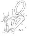
- the zipper assist device 10 preferably includes a wedge-shaped body 12 and a pair of guide channels 14, 16 formed on opposing sides of the body 12.
- a handle 22 in the form of a ring is provided that connects to the body 12 and allows manual operation by inserting one or two fingers through the handle 22 in order to pull the body 12.
- the body 12 may take any shape that enables the body 12 to draw the tracks 6, 8 sufficiently together to permit easy closure of the zipper 2.
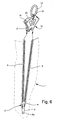
- the zipper assist device 10 assists a patient or operator in pulling a zipper 2 along a pair of tracks 6, 8, to close or open a compression hose product 1 as shown in sequential order in Figures 6-11 .
- the tracks 6, 8 are typically sewn into the compression hose 1 by stitching.
- a central slider 4 acts to interlock respective teeth of the pair of tracks 6, 8 to interlock the tracks 6, 8 as needed to operate the zipper 2.
- the slider 4 includes a tab 5 for pulling the slider 4.
- the tab 5 includes an opening 5a.
- the compression hose 1 is tight fitted around the patient's leg to serve its therapeutic purpose, and often requires a substantial pulling force on the zipper 2 to bring the opposing edges of the compression hose 1 together around the leg. This substantial pulling force may cause damage to the zipper 2 or the zipper tracks 6, 8.
- the body 12 may be made out of any suitable material including plastic, metal, or any other known material.
- the body 12 need not be constructed in the identical shape shown in Figure 1 , and will be effective with any shape that has a generally diverging pair of guide channels 14, 16 angled to reduce the angle by which the zipper tracks 6-8 diverge as the zipper 2 is closed.
- the body 12 may include a pair of voids as shown in Figure 1 .
- the voids may be provided for ornamental reasons, to save material, or to alter the rigidity of the body 12.
- the body 12 also includes an alignment plate 24 positioned on the attachment point end of the body 12.
- a notch 20 is formed in the body 12 and has a shape that approximates that of the zipper slider 4 such that the zipper slider 4 is able to be received within the notch 20.
- An alignment plate 24 is adapted for sliding underneath and receiving the central slider 4. In this manner, the alignment plate 24 slides underneath the tracks 6, 8, and thereby provides guiding support for the central slider 4.
- the handle 22 is connected to the body 12 by a retaining ring 26 that fits within opening 25 formed in the body 12.
- the retaining ring 26 provides for rotation of the handle 22 so that the wearer can easily gain access to the handle 22 from a variety of angles.
- retaining ring 26 may not be required and handle 22 may be attached directly to opening 25 of the body 12.
- the handle 22 is shown in the shape of a ring, but any suitable shape capable of being grasped, or through which one or more fingers may be inserted, is appropriate.
- the pair of guide channels 14,16 are positioned on opposing sides of the body 12. Each channel 14, 16 is shown in a generally concave shape in respect to the center of the wedge-shaped body 14, but can be fabricated in other shapes. Each channel 14, 16 is cylindrically shaped to receive the teeth portion of zipper tracks 6, 8.
- the channels 14, 16 may be made of the same material as the body 12, or may be a different material integrally formed with the body 12. Preferably, each guide channel 14, 16 is made from a durable and low friction material such as metal, but may optionally be made from Delrin ® , Teflon ® , or any suitable material.
- Each guide channel 14, 16 also includes a respective access slot 28, 30 extending from each guide channel 14, 16. Access slots 28, 30 receive a respective one of the zipper tracks 6, 8.
- each access slot, 28, 30, and each channel 14, 16 approximate the contour of the zipper tracks 6, 8 and retain the zipper tracks in the guide channels 14, 16.
- the respective shape of each access slot, 28, 30, and each channel 14, 16, is designed to reduce concentrated stresses and friction by reducing the angle at which the zipper tracks 6, 8 are closed, and providing a gradual transition between their initial angle, such as is shown in Figure 8 .
- the access slots, 28, 30 are also made of a durable and low friction material.
- Each channel 14, 16, includes a beveled surface 15, 17 at the upper end of each channel 14, 16, respectively, for providing ease of ingress and egress of the zipper tracks 6, 8.
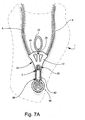
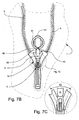
- the wedge shaped body 12 and handle 22 are sized so that the handle 84 of the pull tab extension member is in a generally overlapping and coextensive orientation relative to the handle 22 such that the operator can grasp the handle 22 and the handle 84 simultaneously, as is shown in, for example, Figure 7B .
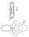
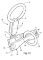
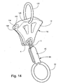
- the pull tab extension member 80 shown in Figures 12 through 16 includes a pair of spaced-apart flanges 82 whose distance is spanned by a post 81 connecting the pair of spaced-apart flanges 82.
- Post 81 is secured to one of the pair of spaced-apart flanges 82 and is adapted to fit within a corresponding opening formed on the other of the pair of spaced-apart flanges 82.
- the pair of spaced-apart flanges 82 are generally flexible such that the flange of the pair of spaced-apart flanges 82 that is not attached to the post 81 is bendable to define an opening between the pair of spaced-apart flanges 82 so that the tab opening 5a may slide in between the pair of spaced-apart flanges 82 and receive post 81.
- the flanges 82 are then released and the post 81 is fitted within the corresponding opening formed on the other flange of the pair of spaced-apart flanges 82.
- the pull tab extension member 80 is then secured to the pull tab 5.
- a handle 84 that, like handle 22, may be in the form of a ring through which one or two fingers may be inserted, is attached to the pair of spaced-apart flanges 82 and is sized such that it is in a generally overlapping or coextensive position with handle 22 when flipped upwards as shown in the Figure 7B .
- handle 84 of the pull tab extension member 80 and handle 22 of the zipper assist device 10 are sized so that the operator's finger will easily fit through both handles 22, 84.
- the zipper assist device 10 operates to reduce the initial angle between the zipper tracks 6, 8 and then maintain a gradual, consistent zipper closing angle ⁇ to reduce stresses on the zipper tracks 6, 8.
- the zipper closing angle ⁇ will vary depending on the size of body 12.
- the pair of guide channels 14, 16 form respective guide angles ⁇ which collectively form the angle ⁇ .
- angle ⁇ is preferably about 50 degrees as measured from the topmost portion of the guide channels 14, 16. It shall be appreciated that due to the concave shape of the guide channels 14, 16, the relative zipper closing angle ⁇ becomes progressively larger as the zipper tracks 6,8, travel through the guide channels 14, 16.
- An arcuate recess 27 is formed on one surface of the body 12 for providing clearance to the limb onto which the garment 1 is being donned.
- the arcuate recess 27 is formed on the surface opposite the surface having notch 20.
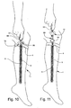
- FIG. 6 Operation of the zipper assist device 10 on a compression hose 1 is shown according to Figures 6 through 11 .
- the central slider 4 of the zipper 2 is preferably in its completely unzipped position.
- the body 12 is then positioned proximal the unzipped portion of the zipper tracks 6, 8, which are shown at the most upwardly position in Figure 6 .
- Each track 6, 8 is positioned proximal to each respective guide channel 14, 16 of the body 12. It may be possible to insert both tracks 6, 8 simultaneously into both guide channels 14, 16, but it is assumed that the wearer will preferably insert one track 6 or 8 into its respective guide channel 14 or 16, and then insert the second track 6 or 8 into its respective guide channel 14 or 16.
- the body 12 is then slid down the zipper tracks 6, 8 until the body 12 is in close proximity to the zipper 2.
- the alignment plate 24 of the body 12 slides underneath the central slider 4 thereby providing increased support for the zipper 2.
- zipper pull tab extension member 80 is attached to the tab 5 to extend the zipper pull tab 5 such that the handle 84 of the zipper pull tab extension member 80 is in general overlapping or coextensive alignment with handle 22.
- the wearer then pulls on the handle 22 of the body 12 and handle 84 of the extension member 80 to move the zipper assist device 10 along the length of the zipper tracks 6, 8, closing zipper 2, as shown sequentially in Figures 8, 9 , and 10 .
- the zipper assist device 10 is then removed from the zipper 2 by releasing the zipper pull tab extension member 80. In this manner, the extension member 80 flips downward as shown in Figure 11 , and the body 12 is then pulled away from the garment 1 and the extension member 80.
- the zipper pull tab extension member 80 may be removed by completing the steps required for installing the member 80 in reverse order.
- the garment 1 may be sold with the zipper pull tab extension member 80 already installed and the extension member 80 may be left attached to the zipper pull tab 5 during use.
- the zipper assist device 100 includes a wedge-shaped body 112 and a pair of guide channels 114, 116 formed on opposing sides of the body 112, a handle 122 that interconnects with opening 125 formed in the body 112 and a pull tab extension member 80.
- Each guide channel 114, 116 has respective access slots 128, 130. Additionally, each guide channel 114, 116 provides a beveled surface 114,117 for ease of ingress and egress of the zipper tracks 6, 8.
- the body 112 includes an alignment plate 124 respectively positioned on the connection end of the body 112. Alignment plate 124 is adapted for sliding underneath and receiving the central slider 4 of the zipper 2. In this manner, the alignment plate 124 acts to slide underneath the tracks 6, 8, providing guiding support for the central slider 4.
Landscapes
- Slide Fasteners (AREA)
Claims (13)
- Vorrichtung (10, 100), die das Öffnen und Schließen eines Reißverschlusses der Art unterstützt, die einen Reißverschlussschieber (4) mit einer Zuglasche (5) hat, der den Reißverschluss (2) öffnet und schließt, indem er ein Paar gegenüberliegende miteinander verriegelbare Reißverschlussschließketten (6, 8) gezielt voneinander trennt bzw. miteinander verbindet, wenn sich der Reißverschlussschieber in der Öffnungs- bzw. Schließrichtung entlang den Reißverschlussschließketten bewegt, umfassend:(a) einen Körper (12) mit einem ersten und einem zweiten auseinandergehenden Führungskanal (14, 16; 114, 116), die jeweilige Führungswinkel zur Aufnahme der jeweiligen Reißverschlussschließketten definieren, um die Reißverschlussschließketten gleitend und nicht verriegelnd durch die Führungskanäle vor dem Reißverschlussschieber zu bewegen, um den Schließwinkel der Reißverschlussschließketten vor dem Reißverschlussschieber zu reduzieren, so dass er dem Führungswinkel der Führungskanäle entspricht, und(b) einen vom Körper (12) getragenen Griff (22, 122), um eine manuelle Zugbewegung des Körpers entlang mindestens einem Abschnitt der Länge des Reißverschlusses zu gestatten, dadurch gekennzeichnet, dass sie ferner Folgendes umfasst:(c) ein separates Reißverschlusszuglaschenverlängerungselement (80), das entfernbar an der Reißverschlusszuglasche (5) angebracht werden kann und einen Griff (84) hat und im Gebrauch allgemein in einer flächengleichen Ausrichtung bezüglich des Körpers (12) positioniert ist, so dass eine Bedienperson beim Schieben des Reißverschlussschiebers in der Schließrichtung gleichzeitig den Griff (84) des Verlängerungselements (80) und den Griff (22, 122) ergreifen kann.
- Vorrichtung nach Anspruch 1, wobei der Körper (12) keilförmig ist.
- Vorrichtung nach Anspruch 1, wobei der erste und der zweite Führungskanal (14, 16), die auseinandergehen, jeweilige gegenüberliegende konkave Flächen bezüglich einer Mittellinie des Körpers definieren.
- Vorrichtung nach Anspruch 1, wobei der Körper eine Öffnung (25, 125) aufweist, die den vom Körper getragenen Griff aufnimmt.
- Vorrichtung nach Anspruch 1, wobei jeder Führungskanal ferner relativ schmale Zugriffsschlitze aufweist, die in einem Umfang jedes Führungskanals ausgebildet sind, um jede Reißverschlussschließkette im jeweiligen Führungskanal aufzunehmen und zu halten.
- Vorrichtung nach Anspruch 1, wobei der Körper ferner eine Ausrichtungsplatte (14, 124) aufweist, die an einem Verriegelungspunkt des Reißverschlussschiebers positioniert ist, um während der Zugbewegung des Körpers für eine Gleitstützung des Reißverschlusses zu sorgen, um die Vorrichtung zu unterstützen und sie auf die Reißverschlussschließkette ausgerichtet zu halten.
- Vorrichtung nach Anspruch 1, wobei jeder Führungskanal ferner eine Abfasung an einem Ende jedes Führungskanals aufweist, damit jede Reißverschlussschließkette leicht eintreten und austreten kann.
- Vorrichtung nach Anspruch 1, wobei der Körper eine Kerbe (20) aufweist, deren Gestalt der Gestalt des Reißverschlussschiebers nahekommt, um den Reißverschlussschieber darin aufzunehmen.
- Vorrichtung nach Anspruch 8, wobei die Kerbe proximal der Zugriffsplatte ausgebildet ist, so dass der Reißverschlussschieber auf die Platte und in die Kerbe gleiten kann.
- Vorrichtung nach Anspruch 1, ferner mit einer bogenförmigen Aussparung, die an einer Fläche gegenüber der Kerbe definiert ist, um Freiraum für eine Gleitbewegung um eine Gliedmaße eines Patienten bereitzustellen.
- Verfahren zum Unterstützen des Schließens eines Reißverschlusses der Art, die einen Reißverschlussschieber (4) mit einer Zuglasche (5) zum Schließen und Öffnen des Reißverschlusses hat, indem ein Paar gegenüberliegende miteinander verriegelbare Schließketten gezielt voneinander getrennt bzw. miteinander verbunden werden, wenn sich der Reißverschlussschieber in der Schließ- bzw. Öffnungsrichtung entlang den Schließketten bewegt, umfassend die folgenden Schritte:(a) Bereitstellen einer Vorrichtung, die einen Körper (12) mit einem ersten und einem zweiten auseinandergehenden Führungskanal (14, 16; 114, 116) zur Aufnahme der jeweiligen Reißverschlussschließketten aufweist, um die Reißverschlussschließketten gleitend und nicht verriegelnd durch den Führungskanal zu bewegen, bevor der mittlere Reißverschlussschieber die Paare verriegelbarer Schließketten gezielt verbindet, um den Schließwinkel der Reißverschlussschließketten vor dem Reißverschlussschieber zu reduzieren, und eines vom Körper (12) getragenen Griffs (22, 122), um eine manuelle Zugbewegung des Körpers zu gestatten,(b) Einführen jeder Schließkette in einen der jeweiligen Führungskanäle,(c) Schieben der Vorrichtung in eine zum Reißverschlussschieber proximale Position,(d) Ergreifen des vom Körper getragenen Griffs (22, 122) und des Griffs (84) eines separaten Reißverschlusszuglaschenverlängerungselements (80), das an der Reißverschlusszuglasche angebracht ist, und(e) Bewegen der Vorrichtung durch manuelles Betätigen des Griffs (22, 122; 84) entlang den Reißverschlussschließketten zum Schließen des Reißverschlusses.
- Verfahren nach Anspruch 11, wobei der Schritt des Einführens jeder Schließkette in einen jeweiligen Führungskanal gleichzeitig durchgeführt wird.
- Verfahren nach Anspruch 11, wobei der Schritt des Einführens jeder Schließkette in einen jeweiligen Führungskanal sequenziell durchgeführt wird.
Applications Claiming Priority (2)
| Application Number | Priority Date | Filing Date | Title |
|---|---|---|---|
| US12/478,224 US8371003B2 (en) | 2009-06-04 | 2009-06-04 | Device for opening and closing a zipper |
| PCT/US2009/046554 WO2010141029A1 (en) | 2009-06-04 | 2009-06-08 | Device for opening and closing a zipper |
Publications (3)
| Publication Number | Publication Date |
|---|---|
| EP2437639A1 EP2437639A1 (de) | 2012-04-11 |
| EP2437639A4 EP2437639A4 (de) | 2012-12-12 |
| EP2437639B1 true EP2437639B1 (de) | 2014-08-13 |
Family
ID=43297992
Family Applications (1)
| Application Number | Title | Priority Date | Filing Date |
|---|---|---|---|
| EP09845643.7A Active EP2437639B1 (de) | 2009-06-04 | 2009-06-08 | Vorrichtung zum öffnen und schliessen eines reissverschlusses |
Country Status (9)
| Country | Link |
|---|---|
| US (1) | US8371003B2 (de) |
| EP (1) | EP2437639B1 (de) |
| JP (1) | JP5474185B2 (de) |
| AU (1) | AU2009347196B2 (de) |
| CA (1) | CA2734556C (de) |
| ES (1) | ES2513840T3 (de) |
| MX (1) | MX2011002219A (de) |
| WO (1) | WO2010141029A1 (de) |
| ZA (1) | ZA201101051B (de) |
Families Citing this family (5)
| Publication number | Priority date | Publication date | Assignee | Title |
|---|---|---|---|---|
| US8631543B2 (en) * | 2010-10-22 | 2014-01-21 | Magna International Inc. | Zipper pre-gather device |
| US20150150322A1 (en) * | 2012-10-01 | 2015-06-04 | Alfredo Mauricio FRAGA-ROSENFELD | Expandable glove with lateral closure |
| US9301632B2 (en) * | 2013-12-20 | 2016-04-05 | Cory Harris | Zipper assist device and method |
| JP2016198270A (ja) * | 2015-04-09 | 2016-12-01 | Ykk株式会社 | スライダー及びスライダー操作具 |
| CN115067637B (zh) * | 2022-08-10 | 2025-06-03 | 佛吉亚(无锡)座椅部件有限公司 | 一种用于座椅滑轨上方便咬合的拉链结构 |
Family Cites Families (26)
| Publication number | Priority date | Publication date | Assignee | Title |
|---|---|---|---|---|
| US2178885A (en) | 1936-12-08 | 1939-11-07 | Buff | Double closure, jointly operated, for flexible articles |
| US2483057A (en) | 1945-10-08 | 1949-09-27 | William C Levering | Sliding fastener |
| BE504247A (de) | 1950-08-26 | |||
| US2854722A (en) * | 1953-05-11 | 1958-10-07 | George H Ruding | Slide actuator for slide fasteners |
| US2887751A (en) * | 1956-10-26 | 1959-05-26 | Kay R Lamb | Ladies' zipper puller |
| US2900205A (en) * | 1957-08-26 | 1959-08-18 | Cirone Joseph | Slide fastener handle |
| USRE25250E (en) | 1958-02-10 | 1962-10-02 | Morgan | |
| US3006051A (en) * | 1958-09-23 | 1961-10-31 | William Lesse | Zipper pull and guard device |
| US3145041A (en) | 1962-01-12 | 1964-08-18 | Richard A Grolig | Zipper hook |
| US3284865A (en) | 1964-11-23 | 1966-11-15 | Muriel H Cavanagh | Slide fastener actuators |
| US3355779A (en) * | 1966-03-03 | 1967-12-05 | Hurst Tim | Device for closing zippers |
| JPS4918701U (de) * | 1972-05-24 | 1974-02-16 | ||
| US3836189A (en) * | 1973-02-02 | 1974-09-17 | D Borrelli | Zipper pull |
| US4022506A (en) * | 1976-02-27 | 1977-05-10 | Cloud Sr James R | Zipper operator |
| US4350375A (en) | 1980-02-08 | 1982-09-21 | Presto Lock, Inc. | Double-slider zipper latching device |
| US4757577A (en) | 1986-09-02 | 1988-07-19 | William Freeman | Multi-way slide fastener and structural support |
| US5008985A (en) * | 1987-12-15 | 1991-04-23 | Thompson Allister W | Zipper securing device |
| JPH0753122B2 (ja) * | 1988-12-14 | 1995-06-07 | ワイケイケイ株式会社 | スライドファスナー用施錠スライダー |
| US5975386A (en) | 1998-08-20 | 1999-11-02 | Fernicola; Linda Carol | Tool for pulling zippers located on the back of garments |
| US6510593B1 (en) * | 1999-09-02 | 2003-01-28 | Young S. Kim | Lockable slide fastener |
| EP1558104A4 (de) * | 2002-09-20 | 2006-12-20 | Gear Inc Z | Mehrbahniges reissverschlusssystem |
| US6742225B2 (en) | 2002-09-20 | 2004-06-01 | Z Gear, Inc. | Connect-release zipping system |
| US7043802B2 (en) * | 2003-01-30 | 2006-05-16 | Illinois Tool Works Inc | Zipper pull with whistle |
| US7073233B2 (en) * | 2004-03-22 | 2006-07-11 | Ykk Europe Limited | Slide fastener |
| JP2009089750A (ja) * | 2007-10-04 | 2009-04-30 | Natsu Morimoto | ブーツ着用補助具及びそれが取り付けられた提げ紐 |
| KR100910706B1 (ko) * | 2007-11-07 | 2009-08-04 | 전필동 | 체결 안정도가 우수한 지퍼 |
-
2009
- 2009-06-04 US US12/478,224 patent/US8371003B2/en active Active
- 2009-06-08 WO PCT/US2009/046554 patent/WO2010141029A1/en not_active Ceased
- 2009-06-08 MX MX2011002219A patent/MX2011002219A/es active IP Right Grant
- 2009-06-08 JP JP2012513919A patent/JP5474185B2/ja active Active
- 2009-06-08 AU AU2009347196A patent/AU2009347196B2/en active Active
- 2009-06-08 ES ES09845643.7T patent/ES2513840T3/es active Active
- 2009-06-08 EP EP09845643.7A patent/EP2437639B1/de active Active
- 2009-06-08 CA CA2734556A patent/CA2734556C/en active Active
-
2011
- 2011-02-09 ZA ZA2011/01051A patent/ZA201101051B/en unknown
Also Published As
| Publication number | Publication date |
|---|---|
| MX2011002219A (es) | 2011-03-30 |
| WO2010141029A1 (en) | 2010-12-09 |
| AU2009347196A1 (en) | 2010-12-09 |
| JP2012528669A (ja) | 2012-11-15 |
| ZA201101051B (en) | 2012-05-30 |
| ES2513840T3 (es) | 2014-10-27 |
| CA2734556A1 (en) | 2010-12-09 |
| JP5474185B2 (ja) | 2014-04-16 |
| EP2437639A1 (de) | 2012-04-11 |
| AU2009347196B2 (en) | 2014-05-29 |
| EP2437639A4 (de) | 2012-12-12 |
| US8371003B2 (en) | 2013-02-12 |
| CA2734556C (en) | 2013-12-24 |
| US20100306971A1 (en) | 2010-12-09 |
Similar Documents
| Publication | Publication Date | Title |
|---|---|---|
| US8528115B2 (en) | Zipper arrangement with foldable pull | |
| US9445644B2 (en) | Footwear with sliding cap | |
| EP2437639B1 (de) | Vorrichtung zum öffnen und schliessen eines reissverschlusses | |
| US20140109366A1 (en) | Zipper Repair Tool | |
| US8590118B2 (en) | Closure arrangement with opening in stationary member | |
| US20070289110A1 (en) | Slide fastener for garments | |
| US8484811B2 (en) | Zipper arrangement with wheeled slider | |
| US5975386A (en) | Tool for pulling zippers located on the back of garments | |
| EP2405781B1 (de) | Vorrichtung zum öffnen und schliessen eines reissverschlusses | |
| US7721353B2 (en) | Hand covering with a hood and a movement mechanism | |
| US20200214401A1 (en) | Slide closure with stabilizing fins and associated garment | |
| US9498076B1 (en) | Zipper pull assist tool | |
| US20150173545A1 (en) | Zipper assist device and method | |
| US20050176317A1 (en) | Fin with a blade having adjustable closed area | |
| US12593898B1 (en) | Seperable slide fastener actuating device | |
| US20030189345A1 (en) | Zipper assist device | |
| FR2856247A1 (fr) | Vetement pour personne souffrant d'un handicap de type vetement couvrant le tronc de la personne | |
| EP4201241A1 (de) | Kleidungsstück | |
| JP3193236U (ja) | 背面ファスナー開閉補助具 | |
| CA2592202A1 (en) | Slide fastener for garments | |
| BR102018075759A2 (pt) | Dispositivo para acionamento de fecho ecler | |
| JP2003225114A (ja) | ショルダーベルト付き手提げ鞄及び手提げ鞄用ショルダーベルト |
Legal Events
| Date | Code | Title | Description |
|---|---|---|---|
| PUAI | Public reference made under article 153(3) epc to a published international application that has entered the european phase |
Free format text: ORIGINAL CODE: 0009012 |
|
| 17P | Request for examination filed |
Effective date: 20110218 |
|
| AK | Designated contracting states |
Kind code of ref document: A1 Designated state(s): AT BE BG CH CY CZ DE DK EE ES FI FR GB GR HR HU IE IS IT LI LT LU LV MC MK MT NL NO PL PT RO SE SI SK TR |
|
| DAX | Request for extension of the european patent (deleted) | ||
| A4 | Supplementary search report drawn up and despatched |
Effective date: 20121108 |
|
| RIC1 | Information provided on ipc code assigned before grant |
Ipc: A47G 25/90 20060101AFI20121102BHEP |
|
| 111Z | Information provided on other rights and legal means of execution |
Free format text: AT BE BG CH CY CZ DE DK EE ES FI FR GB GR HR HU IE IS IT LT LU LV MC MK MT NL NO PL PT RO SE SI SK TR Effective date: 20121213 |
|
| GRAP | Despatch of communication of intention to grant a patent |
Free format text: ORIGINAL CODE: EPIDOSNIGR1 |
|
| INTG | Intention to grant announced |
Effective date: 20140226 |
|
| GRAS | Grant fee paid |
Free format text: ORIGINAL CODE: EPIDOSNIGR3 |
|
| GRAA | (expected) grant |
Free format text: ORIGINAL CODE: 0009210 |
|
| AK | Designated contracting states |
Kind code of ref document: B1 Designated state(s): AT BE BG CH CY CZ DE DK EE ES FI FR GB GR HR HU IE IS IT LI LT LU LV MC MK MT NL NO PL PT RO SE SI SK TR |
|
| REG | Reference to a national code |
Ref country code: GB Ref legal event code: FG4D |
|
| REG | Reference to a national code |
Ref country code: AT Ref legal event code: REF Ref document number: 681609 Country of ref document: AT Kind code of ref document: T Effective date: 20140815 Ref country code: CH Ref legal event code: EP |
|
| REG | Reference to a national code |
Ref country code: IE Ref legal event code: FG4D |
|
| REG | Reference to a national code |
Ref country code: DE Ref legal event code: R096 Ref document number: 602009026054 Country of ref document: DE Effective date: 20140925 |
|
| REG | Reference to a national code |
Ref country code: ES Ref legal event code: FG2A Ref document number: 2513840 Country of ref document: ES Kind code of ref document: T3 Effective date: 20141027 |
|
| REG | Reference to a national code |
Ref country code: NL Ref legal event code: T3 |
|
| REG | Reference to a national code |
Ref country code: LT Ref legal event code: MG4D |
|
| PG25 | Lapsed in a contracting state [announced via postgrant information from national office to epo] |
Ref country code: LT Free format text: LAPSE BECAUSE OF FAILURE TO SUBMIT A TRANSLATION OF THE DESCRIPTION OR TO PAY THE FEE WITHIN THE PRESCRIBED TIME-LIMIT Effective date: 20140813 Ref country code: SE Free format text: LAPSE BECAUSE OF FAILURE TO SUBMIT A TRANSLATION OF THE DESCRIPTION OR TO PAY THE FEE WITHIN THE PRESCRIBED TIME-LIMIT Effective date: 20140813 Ref country code: FI Free format text: LAPSE BECAUSE OF FAILURE TO SUBMIT A TRANSLATION OF THE DESCRIPTION OR TO PAY THE FEE WITHIN THE PRESCRIBED TIME-LIMIT Effective date: 20140813 Ref country code: GR Free format text: LAPSE BECAUSE OF FAILURE TO SUBMIT A TRANSLATION OF THE DESCRIPTION OR TO PAY THE FEE WITHIN THE PRESCRIBED TIME-LIMIT Effective date: 20141114 Ref country code: NO Free format text: LAPSE BECAUSE OF FAILURE TO SUBMIT A TRANSLATION OF THE DESCRIPTION OR TO PAY THE FEE WITHIN THE PRESCRIBED TIME-LIMIT Effective date: 20141113 Ref country code: BG Free format text: LAPSE BECAUSE OF FAILURE TO SUBMIT A TRANSLATION OF THE DESCRIPTION OR TO PAY THE FEE WITHIN THE PRESCRIBED TIME-LIMIT Effective date: 20141113 Ref country code: PT Free format text: LAPSE BECAUSE OF FAILURE TO SUBMIT A TRANSLATION OF THE DESCRIPTION OR TO PAY THE FEE WITHIN THE PRESCRIBED TIME-LIMIT Effective date: 20141215 |
|
| PG25 | Lapsed in a contracting state [announced via postgrant information from national office to epo] |
Ref country code: HR Free format text: LAPSE BECAUSE OF FAILURE TO SUBMIT A TRANSLATION OF THE DESCRIPTION OR TO PAY THE FEE WITHIN THE PRESCRIBED TIME-LIMIT Effective date: 20140813 Ref country code: IS Free format text: LAPSE BECAUSE OF FAILURE TO SUBMIT A TRANSLATION OF THE DESCRIPTION OR TO PAY THE FEE WITHIN THE PRESCRIBED TIME-LIMIT Effective date: 20141213 Ref country code: LV Free format text: LAPSE BECAUSE OF FAILURE TO SUBMIT A TRANSLATION OF THE DESCRIPTION OR TO PAY THE FEE WITHIN THE PRESCRIBED TIME-LIMIT Effective date: 20140813 Ref country code: CY Free format text: LAPSE BECAUSE OF FAILURE TO SUBMIT A TRANSLATION OF THE DESCRIPTION OR TO PAY THE FEE WITHIN THE PRESCRIBED TIME-LIMIT Effective date: 20140813 |
|
| PG25 | Lapsed in a contracting state [announced via postgrant information from national office to epo] |
Ref country code: CZ Free format text: LAPSE BECAUSE OF FAILURE TO SUBMIT A TRANSLATION OF THE DESCRIPTION OR TO PAY THE FEE WITHIN THE PRESCRIBED TIME-LIMIT Effective date: 20140813 Ref country code: DK Free format text: LAPSE BECAUSE OF FAILURE TO SUBMIT A TRANSLATION OF THE DESCRIPTION OR TO PAY THE FEE WITHIN THE PRESCRIBED TIME-LIMIT Effective date: 20140813 Ref country code: RO Free format text: LAPSE BECAUSE OF FAILURE TO SUBMIT A TRANSLATION OF THE DESCRIPTION OR TO PAY THE FEE WITHIN THE PRESCRIBED TIME-LIMIT Effective date: 20140813 Ref country code: SK Free format text: LAPSE BECAUSE OF FAILURE TO SUBMIT A TRANSLATION OF THE DESCRIPTION OR TO PAY THE FEE WITHIN THE PRESCRIBED TIME-LIMIT Effective date: 20140813 Ref country code: IT Free format text: LAPSE BECAUSE OF FAILURE TO SUBMIT A TRANSLATION OF THE DESCRIPTION OR TO PAY THE FEE WITHIN THE PRESCRIBED TIME-LIMIT Effective date: 20140813 Ref country code: EE Free format text: LAPSE BECAUSE OF FAILURE TO SUBMIT A TRANSLATION OF THE DESCRIPTION OR TO PAY THE FEE WITHIN THE PRESCRIBED TIME-LIMIT Effective date: 20140813 |
|
| REG | Reference to a national code |
Ref country code: DE Ref legal event code: R097 Ref document number: 602009026054 Country of ref document: DE |
|
| PG25 | Lapsed in a contracting state [announced via postgrant information from national office to epo] |
Ref country code: PL Free format text: LAPSE BECAUSE OF FAILURE TO SUBMIT A TRANSLATION OF THE DESCRIPTION OR TO PAY THE FEE WITHIN THE PRESCRIBED TIME-LIMIT Effective date: 20140813 |
|
| REG | Reference to a national code |
Ref country code: FR Ref legal event code: PLFP Year of fee payment: 7 |
|
| PLBE | No opposition filed within time limit |
Free format text: ORIGINAL CODE: 0009261 |
|
| STAA | Information on the status of an ep patent application or granted ep patent |
Free format text: STATUS: NO OPPOSITION FILED WITHIN TIME LIMIT |
|
| 26N | No opposition filed |
Effective date: 20150515 |
|
| PGFP | Annual fee paid to national office [announced via postgrant information from national office to epo] |
Ref country code: ES Payment date: 20150626 Year of fee payment: 7 |
|
| PG25 | Lapsed in a contracting state [announced via postgrant information from national office to epo] |
Ref country code: SI Free format text: LAPSE BECAUSE OF FAILURE TO SUBMIT A TRANSLATION OF THE DESCRIPTION OR TO PAY THE FEE WITHIN THE PRESCRIBED TIME-LIMIT Effective date: 20140813 |
|
| PGFP | Annual fee paid to national office [announced via postgrant information from national office to epo] |
Ref country code: BE Payment date: 20150629 Year of fee payment: 7 |
|
| REG | Reference to a national code |
Ref country code: FR Ref legal event code: GC Effective date: 20151208 Ref country code: FR Ref legal event code: GC Effective date: 20151204 |
|
| PG25 | Lapsed in a contracting state [announced via postgrant information from national office to epo] |
Ref country code: MC Free format text: LAPSE BECAUSE OF FAILURE TO SUBMIT A TRANSLATION OF THE DESCRIPTION OR TO PAY THE FEE WITHIN THE PRESCRIBED TIME-LIMIT Effective date: 20140813 |
|
| REG | Reference to a national code |
Ref country code: CH Ref legal event code: PL |
|
| PG25 | Lapsed in a contracting state [announced via postgrant information from national office to epo] |
Ref country code: LU Free format text: LAPSE BECAUSE OF FAILURE TO SUBMIT A TRANSLATION OF THE DESCRIPTION OR TO PAY THE FEE WITHIN THE PRESCRIBED TIME-LIMIT Effective date: 20150608 |
|
| REG | Reference to a national code |
Ref country code: IE Ref legal event code: MM4A |
|
| PG25 | Lapsed in a contracting state [announced via postgrant information from national office to epo] |
Ref country code: LI Free format text: LAPSE BECAUSE OF NON-PAYMENT OF DUE FEES Effective date: 20150630 Ref country code: CH Free format text: LAPSE BECAUSE OF NON-PAYMENT OF DUE FEES Effective date: 20150630 Ref country code: IE Free format text: LAPSE BECAUSE OF NON-PAYMENT OF DUE FEES Effective date: 20150608 |
|
| REG | Reference to a national code |
Ref country code: FR Ref legal event code: GC Effective date: 20160419 |
|
| REG | Reference to a national code |
Ref country code: FR Ref legal event code: PLFP Year of fee payment: 8 |
|
| PGFP | Annual fee paid to national office [announced via postgrant information from national office to epo] |
Ref country code: AT Payment date: 20160519 Year of fee payment: 8 |
|
| PG25 | Lapsed in a contracting state [announced via postgrant information from national office to epo] |
Ref country code: BE Free format text: LAPSE BECAUSE OF NON-PAYMENT OF DUE FEES Effective date: 20160630 Ref country code: MT Free format text: LAPSE BECAUSE OF FAILURE TO SUBMIT A TRANSLATION OF THE DESCRIPTION OR TO PAY THE FEE WITHIN THE PRESCRIBED TIME-LIMIT Effective date: 20140813 |
|
| PG25 | Lapsed in a contracting state [announced via postgrant information from national office to epo] |
Ref country code: HU Free format text: LAPSE BECAUSE OF FAILURE TO SUBMIT A TRANSLATION OF THE DESCRIPTION OR TO PAY THE FEE WITHIN THE PRESCRIBED TIME-LIMIT; INVALID AB INITIO Effective date: 20090608 |
|
| REG | Reference to a national code |
Ref country code: FR Ref legal event code: PLFP Year of fee payment: 9 |
|
| PG25 | Lapsed in a contracting state [announced via postgrant information from national office to epo] |
Ref country code: TR Free format text: LAPSE BECAUSE OF FAILURE TO SUBMIT A TRANSLATION OF THE DESCRIPTION OR TO PAY THE FEE WITHIN THE PRESCRIBED TIME-LIMIT Effective date: 20140813 |
|
| REG | Reference to a national code |
Ref country code: AT Ref legal event code: MM01 Ref document number: 681609 Country of ref document: AT Kind code of ref document: T Effective date: 20170608 |
|
| REG | Reference to a national code |
Ref country code: FR Ref legal event code: RG Effective date: 20180117 |
|
| PG25 | Lapsed in a contracting state [announced via postgrant information from national office to epo] |
Ref country code: ES Free format text: LAPSE BECAUSE OF NON-PAYMENT OF DUE FEES Effective date: 20160609 Ref country code: AT Free format text: LAPSE BECAUSE OF NON-PAYMENT OF DUE FEES Effective date: 20170608 |
|
| REG | Reference to a national code |
Ref country code: FR Ref legal event code: PLFP Year of fee payment: 10 |
|
| PG25 | Lapsed in a contracting state [announced via postgrant information from national office to epo] |
Ref country code: MK Free format text: LAPSE BECAUSE OF FAILURE TO SUBMIT A TRANSLATION OF THE DESCRIPTION OR TO PAY THE FEE WITHIN THE PRESCRIBED TIME-LIMIT Effective date: 20140813 |
|
| REG | Reference to a national code |
Ref country code: ES Ref legal event code: FD2A Effective date: 20181127 |
|
| REG | Reference to a national code |
Ref country code: FR Ref legal event code: PLFP Year of fee payment: 15 |
|
| PGFP | Annual fee paid to national office [announced via postgrant information from national office to epo] |
Ref country code: DE Payment date: 20240627 Year of fee payment: 16 |
|
| PGFP | Annual fee paid to national office [announced via postgrant information from national office to epo] |
Ref country code: NL Payment date: 20240625 Year of fee payment: 16 |
|
| PGFP | Annual fee paid to national office [announced via postgrant information from national office to epo] |
Ref country code: FR Payment date: 20240625 Year of fee payment: 16 |
|
| PGFP | Annual fee paid to national office [announced via postgrant information from national office to epo] |
Ref country code: GB Payment date: 20250617 Year of fee payment: 17 |
|
| REG | Reference to a national code |
Ref country code: DE Ref legal event code: R119 Ref document number: 602009026054 Country of ref document: DE |
|
| REG | Reference to a national code |
Ref country code: NL Ref legal event code: MM Effective date: 20250701 |
|
| PG25 | Lapsed in a contracting state [announced via postgrant information from national office to epo] |
Ref country code: NL Free format text: LAPSE BECAUSE OF NON-PAYMENT OF DUE FEES Effective date: 20250701 |