EP2437357A1 - Connector - Google Patents
Connector Download PDFInfo
- Publication number
- EP2437357A1 EP2437357A1 EP20110007117 EP11007117A EP2437357A1 EP 2437357 A1 EP2437357 A1 EP 2437357A1 EP 20110007117 EP20110007117 EP 20110007117 EP 11007117 A EP11007117 A EP 11007117A EP 2437357 A1 EP2437357 A1 EP 2437357A1
- Authority
- EP
- European Patent Office
- Prior art keywords
- locking lance
- projection
- locking
- connector according
- connector
- Prior art date
- Legal status (The legal status is an assumption and is not a legal conclusion. Google has not performed a legal analysis and makes no representation as to the accuracy of the status listed.)
- Withdrawn
Links
Images


Classifications
-
- H—ELECTRICITY
- H01—ELECTRIC ELEMENTS
- H01R—ELECTRICALLY-CONDUCTIVE CONNECTIONS; STRUCTURAL ASSOCIATIONS OF A PLURALITY OF MUTUALLY-INSULATED ELECTRICAL CONNECTING ELEMENTS; COUPLING DEVICES; CURRENT COLLECTORS
- H01R13/00—Details of coupling devices of the kinds covered by groups H01R12/70 or H01R24/00 - H01R33/00
- H01R13/40—Securing contact members in or to a base or case; Insulating of contact members
- H01R13/42—Securing in a demountable manner
- H01R13/422—Securing in resilient one-piece base or case, e.g. by friction; One-piece base or case formed with resilient locking means
- H01R13/4223—Securing in resilient one-piece base or case, e.g. by friction; One-piece base or case formed with resilient locking means comprising integral flexible contact retaining fingers
-
- H—ELECTRICITY
- H01—ELECTRIC ELEMENTS
- H01R—ELECTRICALLY-CONDUCTIVE CONNECTIONS; STRUCTURAL ASSOCIATIONS OF A PLURALITY OF MUTUALLY-INSULATED ELECTRICAL CONNECTING ELEMENTS; COUPLING DEVICES; CURRENT COLLECTORS
- H01R13/00—Details of coupling devices of the kinds covered by groups H01R12/70 or H01R24/00 - H01R33/00
- H01R13/46—Bases; Cases
- H01R13/502—Bases; Cases composed of different pieces
-
- H—ELECTRICITY
- H01—ELECTRIC ELEMENTS
- H01R—ELECTRICALLY-CONDUCTIVE CONNECTIONS; STRUCTURAL ASSOCIATIONS OF A PLURALITY OF MUTUALLY-INSULATED ELECTRICAL CONNECTING ELEMENTS; COUPLING DEVICES; CURRENT COLLECTORS
- H01R4/00—Electrically-conductive connections between two or more conductive members in direct contact, i.e. touching one another; Means for effecting or maintaining such contact; Electrically-conductive connections having two or more spaced connecting locations for conductors and using contact members penetrating insulation
- H01R4/10—Electrically-conductive connections between two or more conductive members in direct contact, i.e. touching one another; Means for effecting or maintaining such contact; Electrically-conductive connections having two or more spaced connecting locations for conductors and using contact members penetrating insulation effected solely by twisting, wrapping, bending, crimping, or other permanent deformation
- H01R4/18—Electrically-conductive connections between two or more conductive members in direct contact, i.e. touching one another; Means for effecting or maintaining such contact; Electrically-conductive connections having two or more spaced connecting locations for conductors and using contact members penetrating insulation effected solely by twisting, wrapping, bending, crimping, or other permanent deformation by crimping
- H01R4/183—Electrically-conductive connections between two or more conductive members in direct contact, i.e. touching one another; Means for effecting or maintaining such contact; Electrically-conductive connections having two or more spaced connecting locations for conductors and using contact members penetrating insulation effected solely by twisting, wrapping, bending, crimping, or other permanent deformation by crimping for cylindrical elongated bodies, e.g. cables having circular cross-section
- H01R4/184—Electrically-conductive connections between two or more conductive members in direct contact, i.e. touching one another; Means for effecting or maintaining such contact; Electrically-conductive connections having two or more spaced connecting locations for conductors and using contact members penetrating insulation effected solely by twisting, wrapping, bending, crimping, or other permanent deformation by crimping for cylindrical elongated bodies, e.g. cables having circular cross-section comprising a U-shaped wire-receiving portion
- H01R4/185—Electrically-conductive connections between two or more conductive members in direct contact, i.e. touching one another; Means for effecting or maintaining such contact; Electrically-conductive connections having two or more spaced connecting locations for conductors and using contact members penetrating insulation effected solely by twisting, wrapping, bending, crimping, or other permanent deformation by crimping for cylindrical elongated bodies, e.g. cables having circular cross-section comprising a U-shaped wire-receiving portion combined with a U-shaped insulation-receiving portion
-
- H—ELECTRICITY
- H01—ELECTRIC ELEMENTS
- H01R—ELECTRICALLY-CONDUCTIVE CONNECTIONS; STRUCTURAL ASSOCIATIONS OF A PLURALITY OF MUTUALLY-INSULATED ELECTRICAL CONNECTING ELEMENTS; COUPLING DEVICES; CURRENT COLLECTORS
- H01R43/00—Apparatus or processes specially adapted for manufacturing, assembling, maintaining, or repairing of line connectors or current collectors or for joining electric conductors
- H01R43/20—Apparatus or processes specially adapted for manufacturing, assembling, maintaining, or repairing of line connectors or current collectors or for joining electric conductors for assembling or disassembling contact members with insulating base, case or sleeve
- H01R43/22—Hand tools
Definitions
- the present invention relates to a connector.
- Japanese Unexamined Patent Publication No. 2005-216810 discloses a conventional connector.
- This connector includes a terminal fitting and a connector housing in which the terminal fitting is accommodated.
- the connector housing is formed with a cavity, into which the terminal fitting is to be inserted.
- a resiliently deformable locking lance projecting forward in a cantilever manner is formed on an inner surface of the cavity.
- the terminal fitting properly inserted into the cavity is resiliently retained by the locking lance.
- the connector housing is also formed with an excessive deformation preventing portion which comes into contact with the locking lance to stop any further resilient deformation of the locking lance by coming into contact with the locking lance when the locking lance is about to be excessively resiliently deformed.
- the excessive deformation preventing portion is formed by a cavity inner wall facing the locking lance with a deformation space for the locking lance defined therebetween.
- the locking lance, the deformation space for the locking lance and the excessive deformation preventing portion are juxtaposed in a resilient deforming direction of the locking lance.
- the present invention was developed in view of the above situation and an object thereof is to realize the miniaturization of a connector.
- a connector comprising at least one terminal fitting and a connector housing, wherein the connector housing includes at least one cavity into which the terminal fitting is to be at least partly inserted, a front wall capable of stopping the terminal fitting inserted into the cavity at a front end position, and a resiliently deformable locking lance substantially projecting in a cantilever manner from an inner surface of the cavity; the terminal fitting properly inserted in the cavity is resiliently retained by the locking lance; the connector further comprises at least one projection projecting from a side where the front wall is located toward a side where the locking lance is located; and the projection is so arranged as to come into contact with the locking lance from a substantially opposite side in a resilient deforming direction of the locking lance when the locking lance is about to be excessively resiliently deformed.
- the projection comes into contact with the locking lance from the opposite side in the resilient deforming direction of the locking lance when the locking lance is about to be excessively resiliently deformed, any further resilient deformation of the locking lance is stopped.
- the projection projects from the side where the front wall substantially is located toward the side where the locking lance is located, a space in which the projection and the locking lance are juxtaposed in the resilient deforming direction of the locking lance can be made small. As a result, the miniaturization of the connector can be realized.
- a leading end portion of the projection is located on a planned passage path of a leading end portion of the locking lance when the locking lance is about to be excessively resiliently deformed.
- the leading end portions of the locking lance and the projection come into contact with each other. Therefore, the space in which the projection and the locking lance are juxtaposed in the resilient deforming direction of the locking lance can be made smaller.
- the locking lance and the projection include parts which overlap each other in projecting directions of the locking lance and the projection in a state where the locking lance is not resiliently deformed.
- the connector can be miniaturized also in the projecting directions of the locking lance and the projection.
- a tip end of a leading end portion of the projection and a leading end portion of the locking lance do not overlap each other in the resilient deforming direction of the locking lance in a state where the locking lance is not resiliently deformed.
- a partition wall at least partly is formed between two cavities adjacent to each other; and the projection doubles as the partition wall.
- the projection at least partly doubles as the partition wall of the cavity, further miniaturization of the connector can be realized as compared with the case where the projection and the partition wall are juxtaposed in the resilient deforming direction of the locking lance.
- the projection is integrally or unitarily formed to the front wall.
- the connector housing includes a housing main body formed with the at least one cavity and a front holder to be so mounted to the housing main body as to at least partly cover the front surface of the housing main body.
- front wall and/or the projection are formed on the front holder.
- the locking lance and the projection can be mold-formed without any problem even if they include parts which overlap in the resilient deforming direction of the locking lance.
- the locking lance is hidden behind the front wall and cannot be substantially seen from front.
- At least one cutout is formed in the partition wall at the outer lateral side of the locking lance, wherein the locking lances adjacent in the width direction are proximately arranged via the cutouts.
- one or more spaces are formed by cutting out the partition walls between the locking lances in one row and those in another row, wherein the spaces are arranged right before the base end parts of the locking lances, so that in the process of inserting the terminal fitting into the cavity, the locking lance pushed up by the terminal fitting at least partly enters the space.
- a plurality of cavities are formed; wherein the projection includes a first surface portion which supports the terminal fitting properly inserted into the adjacent cavity and a second surface portion substantially parallel to the first surface portion at a side substantially opposite to the first surface portion.
- first surface portion is arranged substantially over the entire length of the projection and/or the second surface portion is arranged at a base part of the projection.
- a leading end surface of the locking lance serves as a locking surface engageable with the terminal fitting, wherein the locking surface preferably is somewhat inclined upward with respect to a vertical axis in the height direction and/or arranged near the front end of the housing main body when the locking lance is in the undeformed state.
- one or more retracted surfaces inclined obliquely downward are formed at portions of the leading end surface of each projection, wherein in the process of resiliently deforming the locking lance, the leading end of the locking lance passes right below the retracted surfaces, thereby avoiding interference with the projection.
- a connector 10 includes a connector housing 20 and one or more terminal fittings 90 to be at least partly accommodated into the connector housing 20.
- the connector housing 20 is connectable to an unillustrated mating connector housing.
- a side to be connected to the mating connector housing is referred to as a front side concerning forward and backward directions.
- Each terminal fitting 90 is integrally or unitarily formed by applying a bending, folding and/or embossing process and the like to an electrically conductive (particularly metal) plate and has a long and narrow shape in forward and backward directions as shown in FIG. 6 .
- This terminal fitting 90 includes a tubular terminal main body 91 and a wire connection portion to be connected with a wire, the wire connection portion particularly comprising a barrel portion 92 in the form of one or more open barrels located behind the terminal main body 91.
- the barrel portion 92 particularly is composed of a wire barrel 93 to be crimped or bent or folded and connected to a core 101 exposed at an end portion of a wire 100 and an insulation barrel 94 located behind the wire barrel 93 and to be crimped or bent or folded and connected to a resilient (rubber) plug 110 mounted on an insulation coating 102 at the end portion of the wire 100.
- a resiliently deformable resilient contact piece 95 is formed particularly by being substantially folded backward at or near the front end of the outer or lower wall of the terminal main body 91 as shown in FIG. 1 .
- a male tab of a mating terminal fitting is to be at least partly inserted into this terminal main body 91 as the two connector housings are connected, and the inserted male tab resiliently comes into contact with the resilient contact piece 95.
- the upper wall of the terminal main body 91 particularly is made up of two walls at least partly placed one over the other in a height direction, and a stepped or recessed lance receiving portion 96 is formed in an intermediate part of the outer wall. Further, a locking projection 97 is formed to project from the outer or upper wall of the terminal main body 91. The locking projection 97 particularly substantially is arranged at a position defining the front edge of the lance receiving portion 96.
- the connector housing 20 is made e.g. of synthetic resin and includes a housing main body 21, a front holder 22 to be so mounted to or on the housing main body 21 as to at least partly cover the front surface of the housing main body 21, a tower portion 23 integrally or unitarily connected to (particularly the lower end of) the housing main body 21 and substantially extending in forward and backward directions, and a fitting tube portion 24 for at least partly covering the housing main body 21 and the tower portion 23 (hereinafter, referred to as housing main body and the like 21, 23). As shown in FIG. 10 , the housing main body and the like 21, 23 and the fitting tube portion 24 are integrally or unitarily connected via a radially extending connecting portion 25.
- connection space 26 is defined at least partly between the housing main body and the like 21, 23 and the fitting tube portion 24, and a receptacle of the mating connector housing at least partly is fittable thereinto from front.
- the front end of the tower portion 23 and that of the fitting tube portion 24 particularly are aligned substantially at the same position and/or arranged before that of the housing main body 21.
- An annular seal member 80 particularly is to be mounted on the outer peripheral surfaces of the housing main body and the like 21, 23.
- the seal member 80 is resiliently held in close contact with the outer peripheral surfaces of the housing main body and the like 21, 23 and the inner peripheral surface of the receptacle to seal between the two connector housings in a fluid- or liquid-tight manner.
- each of the upper and lower outer surfaces of the housing main body and the like 21, 23 particularly are recessed to form a pair of holder engaging portions 27.
- One or more, particularly a pair of supporting shafts 28 are formed to project from the outer (upper and/or lower) outer surface(s) of the fitting tube portion 24.
- a lever 29 (as a particular operable member, see FIG. 4 ) is rotatably or pivotably mounted on the (both) supporting shafts 28 and a connecting operation of the two connector housings can progress by the rotation or pivotal movement of the lever 29 about the supporting shafts 28.
- the operable member may be embodied differently, e.g. by a slider substantially linearly displaceable and exhibiting a cam action to perform or assist the connection of the two housings.
- the housing main body 21 is formed with one or more cavities 30 arranged in one or more, particularly a plurality of rows or stages in a height direction and/or in one or more, particularly a plurality of columns in a width direction.
- the respective cavities 30 penetrate through the housing main body 21 substantially in forward and backward directions.
- the cavities 30 adjacent to each other in the width and/or height directions particularly are at least partly partitioned from each other by one or more partition walls 31.
- the terminal fitting 90 and the resilient (particularly rubber) plug 110 are to be at least partly inserted into each cavity 30 from an insertion side, particularly substantially from behind. With the terminal fitting 90 properly inserted in each cavity 30, the rear end of the rubber plug 110 particularly projects backward from the rear end of the housing main body 21.
- a mount hole or recess 32 for a retainer 70 is formed in a side surface of the housing main body 21.
- the mount hole 32 particularly is formed with such a depth as to communicate with all the one or more cavities 30.
- the retainer 70 is so mounted into the housing main body 21 as to be movable between a partial locking position (first position) and a full locking position (second position).
- retaining portions 71 of the retainer 70 substantially are retracted from the cavities 30 to permit the insertion and withdrawal of the terminal fittings 90 into the cavities 30.
- the retaining portions 71 of the retainer 70 at least partly are located in the cavities 30 to substantially face the rear edges of the terminal main bodies 91, whereby the terminal fittings 90 are retained.
- a locking lance 33 is formed on the lateral (particularly upper) surface of the inner wall of each cavity.
- the locking lance 33 substantially projects forward in a cantilever manner particularly from a position right before the mount hole 32 in the housing main body 21, and is resiliently deformable substantially in the height direction (deformation direction DD intersecting an insertion direction of the terminal fitting 90 into the cavity 30) with a base end part thereof as a supporting point.
- the locking lance 33 in its natural state extends obliquely downward or inwardly from the base end to the leading end thereof, and the locking lance 33 maximally resiliently deformed within a proper resilient deformation range extends substantially horizontally (or along the insertion direction of the terminal fitting 90 into the cavity 30) from the base end to the leading end thereof.
- the leading end surface (front end surface) of the locking lance 33 serves as a locking surface 34 engageable with the locking projection 97 of the terminal fitting 90.
- the locking surface 34 particularly is somewhat inclined upward with respect to a vertical axis in the height direction and/or arranged near the front end of the housing main body 21 when the locking lance 33 is in the natural state.
- One or more cutouts 35 are formed in the partition walls 31 at the (particularly substantially opposite) outer lateral side(s) of the locking lance 33.
- the locking lances 33 adjacent in the width direction are proximately arranged via the cutouts 35.
- spaces 36 are formed by cutting out the partition walls 31 between the locking lances 33 in the lower row and those in the upper row. The spaces 36 are arranged right before the base end parts of the locking lances 33. In the process of inserting the terminal fitting 90 into the cavity 30, the locking lance 33 pushed up by the locking projection 97 at least partly enters this space 36.
- the tower portion 23 is also formed with one or more, particularly a pair of larger cavities 37 particularly substantially arranged in the width direction.
- the larger cavities 37 are larger in cross section and/or longer in forward and backward directions than the cavities 30.
- a resiliently deformable larger locking lance 38 is formed at a side surface (particularly surface orthogonal to the locking lances 33 of the cavities 30) of the inner wall of each larger cavity 37.
- a large-size terminal fitting 90 is to be at least partly inserted into each larger cavity 37 and the properly inserted large-size terminal fitting 90 is resiliently retained by the larger locking lance 38.
- the housing main body 21 particularly is not formed with a wall for stopping the terminal fittings 90 properly inserted into the cavities 30 at their front end positions.
- the tower portion 23 particularly is formed with a wall 39 for stopping the large-size terminal fittings 90 properly inserted into the larger cavities 37 at their front end positions.
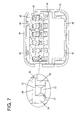
- the front holder 22 is made e.g. of synthetic resin and includes a front wall 40 (particularly substantially in the form of a flat plate) for at least partly covering the front surface of the housing main body 21 and a surrounding portion 41 (particularly substantially in the form of a frame connected to the opposite widthwise ends of the lower surface of the front wall 40 and) at least partly surrounding a front end portion of the tower portion 23 as shown in FIGS. 7 to 9 .
- a front wall 40 particularly substantially in the form of a flat plate
- a surrounding portion 41 particularly substantially in the form of a frame connected to the opposite widthwise ends of the lower surface of the front wall 40 and
- the locking lances 33 are hidden behind the front wall 40 and cannot be substantially seen from front.
- the front wall 40 is formed with one or more, particularly a plurality of tab insertion holes 42 at positions substantially corresponding to the respective cavities 30.
- One or more (particularly substantially conical or converging) guiding portions 43 at least partly are formed on the opening edges of the respective tab insertion holes 42 in the front surface of the front wall 40.
- a tubular portion 44 for at least partly covering the housing main body and the like 21, 23 is formed to substantially project backward from (particularly peripheral edge portions of) the front wall 40 and the surrounding portion 41.
- One or more, particularly a pair of holder locking portions 45 are formed to project from (particularly each of) the upper and/or lower inner surfaces of the tubular portion 44.
- One or more, particularly a plurality of fitting recesses 46 are formed in the rear surface of the front wall 40 at positions substantially corresponding to the respective cavities 30.
- One or more, particularly a plurality of projections 50 are so formed on the rear surface of the front wall 40 as to substantially project backward (toward the locking lances 33).
- the respective projections 50 constitute or form part of the upper walls of the fitting recesses 46.
- the respective projections 50 particularly are arranged substantially at the same height positions as the partition walls 31 and/or leading end portions thereof particularly are arranged at positions displaced from the locking lances 33 in the height direction as shown in FIG. 3 .
- Each projection 50 includes a (particularly substantially horizontal) upper or inner surface portion 51 which supports the terminal main body 91 of the terminal fitting 90 properly inserted into the cavity 30 in the adjacent or upper row from outside or below and/or a lower surface portion substantially parallel to the upper surface portion 51 at a side opposite to the upper surface portion 51.
- the upper surface portion 51 particularly is arranged substantially over the entire length of the projection 50 and/or the lower surface portion 52 particularly is arranged at a base part of the projection 50.
- each projection 50 is recessed in a widthwise intermediate part (particularly substantially in a widthwise central part) to form a receiving groove 53 into which the locking projection 97 of the terminal fitting 90 properly inserted into the cavity 30 at least partly is fitted and inserted.
- the groove surface of the receiving groove 53 includes a substantially horizontal flat surface 54 facing the upper surface of the locking projection 97 and an oblique surface 55 inclined obliquely downward while facing the front edge of the locking projection 97.
- one or more, particularly a pair of retracted surfaces 56 inclined obliquely downward are formed at portions of the leading end surface of each projection 50 at the opposite sides of the receiving groove 53 in the width direction.
- the leading end of the locking lance 33 passes right below the retracted surfaces 56, thereby avoiding interference with the projection 50.
- the leading end portion of the projection 50 is arranged at a position at least partly overlapping a planned passage path of the leading end portion of the locking lance 33 about to be excessively resiliently deformed, i.e. at such a position as to be able to interfere with the leading end of the locking lance 33 in a state where the front holder 22 is mounted to the housing main body 21.
- a contact portion 57 with which the locking lance 33 about to be excessively resiliently deformed can come into contact is formed on the leading end portion of the projection 50.
- This contact portion 57 particularly is arranged between the upper surface portion 51 and the retracted surfaces 56.
- the contact portion 57 is substantially U-shaped and the leading end thereof serves as a tip end 58 which is a rearmost part of the projection 50.
- the leading end portion of the locking lance 33 and that of the projection 50 are so positioned relative to each other as to at least partly overlap each other in forward and backward directions as projecting directions of the locking lances 33 and the projection 50. Further, in the state where the locking lance 33 is not resiliently deformed, an upper part of the locking lance 33 and a lower part of the projection 50 are so positioned relative to each other as to at least partly overlap each other in the height direction as a resilient deforming direction of the locking lance 33.
- the locking surface 34 of the locking lance 33 and the contact portion 57 (including the tip end 58) of the projection 50 are so positioned relative to each other as to be displaced from each other without overlapping each other in the height direction as the resilient deforming direction of the locking lance 33.
- the tip end 58 of the projection 50 is arranged at a position substantially facing the space 36.
- the already described space 36 is provided between the leading end portion of the locking lance 33 and the tip end 58 of the projection 50.
- the retainer 70 Upon accommodating the one or more terminal fittings 90 into the connector housing 20, the retainer 70 is first held or positioned at the partial locking position and the front holder 22 is mounted to the connector housing 20.
- the (particularly each) terminal fitting 90 is at least partly inserted into the cavity 30 from the insertion side, particularly substantially from behind.
- the locking projection 97 interferes with the locking lance 33 and resiliently deforms the locking lance 33 in the deforming direction DD toward the space 35.
- the locking lance 33 is maximally resiliently deformed within the normal resilient deformation range and the locking surface 34 of the locking lance 33 approaches the contact portion 57 of the projection 50 as shown in FIG. 1 .
- the locking lance 33 is excessively resiliently deformed beyond the normal resilient deformation range, for example, due to inclination of the terminal fitting 90 from its proper insertion posture, the locking surface 34 of the locking lance 33 comes into contact with the contact portion 57 of the projection 50.
- the locking lance 33 particularly is prevented from entering the cavity 30 in the upper row and an inserting operation of the terminal fitting 90 into the cavity 30 in the upper row can be performed without any problem.
- the terminal fitting 90 When the terminal fitting 90 is properly inserted into the cavity 30, the front end portion of the terminal main body 91 is properly fitted into the fitting recess 46, the locking projection 97 is properly fitted into the receiving groove 53 and the terminal main body 91 comes into contact with the front wall 40 to be stopped at its front end position as shown in FIG. 2 .
- the locking projection 97 passes the locking lance 33, the locking lance 33 resiliently at least partly returns, the leading end portion thereof at least partly enters the lance receiving portion 96 and the locking surface 34 thereof is so arranged as to be able to come into contact with the locking projection 97 from a withdrawal side, particularly substantially from behind. In this way, the terminal fitting 90 is retained and held in the cavity 30. Thereafter, the retainer 70 is pushed to the full locking position (second position) to doubly retain the terminal fittings 90.
- an unillustrated jig is at least partly inserted into the cavity 30 through a jig insertion hole 49 (see FIG. 8 ) formed in the front wall 40 of the front holder 22 after the retainer 70 is returned to the partial locking position (first position).
- the locking lance 33 is hooked by the leading end of the jig and, in this state, lifted up to be resiliently deformed, whereby the locking surface 34 of the locking lance 33 substantially is retracted from the locking projection 97 of the terminal fitting 90 and the terminal fitting 90 can be withdrawn from the cavity 30.
- the locking lance 33 may be excessively resiliently deformed by the jig, but the locking surface 34 of the locking lance 33 comes into contact with the contact portion 57 of the projection 50, thereby stopping any further resilient deformation of the locking lance 33 to prevent an excessive deformation of the locking lance 33.
- the excessive deformation of each locking lance 33 is prevented by the projection 50.
- the projection 50 projects from a side where the front wall 40 is located to a side where the locking lance 33 is located, a space in which the projection 50 is juxtaposed with the locking lance 33 in the resilient deforming direction of the locking lance 33 (height direction) can be made small. As a result, the miniaturization of the connector 10 can be realized.
- the leading end portion of the projection 50 By locating the leading end portion of the projection 50 on the planned passage path of the leading end portion of the locking lance 33 about to be excessively resiliently deformed, the leading end portions of the locking lance 33 and the projection 50 come into contact with each other. Therefore, the space in which the projection 50 is juxtaposed with the locking lance 33 in the resilient deforming direction DD of the locking lance 33 can be made smaller.
- the connector 10 can be miniaturized also in forward and backward directions. Further, since the tip end 58 of the leading end portion of the projection 50 and the locking surface 34 of the locking lance 33 do not overlap each other in the height direction in the state where the locking lance 33 is not resiliently deformed, the space 36 is ensured to have a specified (predetermined or predeterminable) large dimension.
- the projections 50 particularly double as the partition walls 31 of the cavities 30, further miniaturization of the connector 10 can be realized as compared with the case where the projections 50 and the partition walls 31 are juxtaposed in the height direction.
- the projections 50 and the front wall 40 particularly are integrally or unitarily formed, a complicated construction can be avoided. Furthermore, since the front wall 40 and the projections 50 particularly are formed on the front holder 22, the locking lances 33 and the projections 50 can be mold-formed without any problem even if they include parts which overlap in the resilient deforming direction of the locking lances 33.
- a connector housing 20 includes one or more cavities 30 into which one or more terminal fittings 90 are to be at least partly inserted, a front wall 40 capable of stopping the one or more terminal fittings 90 inserted into the cavities 30 at front end positions, and one or more resiliently deformable locking lances 33 substantially projecting in a cantilever manner from inner surfaces of the cavities 30.
- OINe or more respective projections 50 are also provided which project from a side where the front wall 40 is located toward a side where the locking lances 33 are located.
- the projections 50 are so arranged as to come into contact with the locking lances 33 from an opposite side in a resilient deforming direction DD of the locking lances 33 when the locking lances 33 are about to be excessively resiliently deformed.
Abstract
Description
- The present invention relates to a connector.
- Japanese Unexamined Patent Publication No.
2005-216810 - In the case of the above conventional connector, the locking lance, the deformation space for the locking lance and the excessive deformation preventing portion are juxtaposed in a resilient deforming direction of the locking lance. Thus, it may not be possible to sufficiently miniaturize the connector in the resilient deforming direction of the locking lance.
- The present invention was developed in view of the above situation and an object thereof is to realize the miniaturization of a connector.
- This object is solved according to the invention by the features of the independent claim. Particular embodiments of the invention are subject of the dependent claims.
- According to the invention, there is provided a connector, comprising at least one terminal fitting and a connector housing, wherein the connector housing includes at least one cavity into which the terminal fitting is to be at least partly inserted, a front wall capable of stopping the terminal fitting inserted into the cavity at a front end position, and a resiliently deformable locking lance substantially projecting in a cantilever manner from an inner surface of the cavity; the terminal fitting properly inserted in the cavity is resiliently retained by the locking lance; the connector further comprises at least one projection projecting from a side where the front wall is located toward a side where the locking lance is located; and the projection is so arranged as to come into contact with the locking lance from a substantially opposite side in a resilient deforming direction of the locking lance when the locking lance is about to be excessively resiliently deformed.
- Since the projection comes into contact with the locking lance from the opposite side in the resilient deforming direction of the locking lance when the locking lance is about to be excessively resiliently deformed, any further resilient deformation of the locking lance is stopped. In this case, since the projection projects from the side where the front wall substantially is located toward the side where the locking lance is located, a space in which the projection and the locking lance are juxtaposed in the resilient deforming direction of the locking lance can be made small. As a result, the miniaturization of the connector can be realized.
- According to a particular embodiment, a leading end portion of the projection is located on a planned passage path of a leading end portion of the locking lance when the locking lance is about to be excessively resiliently deformed.
- By locating the leading end portion of the projection on the planned passage path of the leading end portion of the locking lance about to be excessively resiliently deformed, the leading end portions of the locking lance and the projection come into contact with each other. Therefore, the space in which the projection and the locking lance are juxtaposed in the resilient deforming direction of the locking lance can be made smaller.
- Particularly, the locking lance and the projection include parts which overlap each other in projecting directions of the locking lance and the projection in a state where the locking lance is not resiliently deformed.
- Since the locking lance and the projection include the parts that overlap each other in the projecting directions of the locking lance and the projection in the state where the locking lance is not resiliently deformed, the connector can be miniaturized also in the projecting directions of the locking lance and the projection.
- Further particularly, a tip end of a leading end portion of the projection and a leading end portion of the locking lance do not overlap each other in the resilient deforming direction of the locking lance in a state where the locking lance is not resiliently deformed.
- Since the tip end of the leading end portion of the projection and the leading end portion of the locking lance do not overlap each other in the resilient deforming direction of the locking lance in the state where the locking lance is not resiliently deformed, a deformation space for the locking lance is ensured to have a specified large dimension.
- Further particularly, wherein a plurality of cavities are formed; a partition wall at least partly is formed between two cavities adjacent to each other; and the projection doubles as the partition wall.
- Since the projection at least partly doubles as the partition wall of the cavity, further miniaturization of the connector can be realized as compared with the case where the projection and the partition wall are juxtaposed in the resilient deforming direction of the locking lance.
- Further particularly, the projection is integrally or unitarily formed to the front wall.
- Since the projection and the front wall are integrally or unitarily formed, a complicated construction can be avoided.
- Further particularly, wherein the connector housing includes a housing main body formed with the at least one cavity and a front holder to be so mounted to the housing main body as to at least partly cover the front surface of the housing main body.
- Further particularly, the front wall and/or the projection are formed on the front holder.
- Since the front wall and/or the projection are formed on the front holder, the locking lance and the projection can be mold-formed without any problem even if they include parts which overlap in the resilient deforming direction of the locking lance.
- Further particularly, when the front surface of the housing is at least partly covered by the front wall, the locking lance is hidden behind the front wall and cannot be substantially seen from front.
- Further particularly, at least one cutout is formed in the partition wall at the outer lateral side of the locking lance, wherein the locking lances adjacent in the width direction are proximately arranged via the cutouts.
- Further particularly, one or more spaces are formed by cutting out the partition walls between the locking lances in one row and those in another row, wherein the spaces are arranged right before the base end parts of the locking lances, so that in the process of inserting the terminal fitting into the cavity, the locking lance pushed up by the terminal fitting at least partly enters the space.
- Further particularly, a plurality of cavities are formed; wherein the projection includes a first surface portion which supports the terminal fitting properly inserted into the adjacent cavity and a second surface portion substantially parallel to the first surface portion at a side substantially opposite to the first surface portion.
- Further particularly, the first surface portion is arranged substantially over the entire length of the projection and/or the second surface portion is arranged at a base part of the projection.
- Further particularly, a leading end surface of the locking lance serves as a locking surface engageable with the terminal fitting,
wherein the locking surface preferably is somewhat inclined upward with respect to a vertical axis in the height direction and/or arranged near the front end of the housing main body when the locking lance is in the undeformed state. - Further particularly, one or more retracted surfaces inclined obliquely downward are formed at portions of the leading end surface of each projection, wherein in the process of resiliently deforming the locking lance, the leading end of the locking lance passes right below the retracted surfaces, thereby avoiding interference with the projection.
- These and other objects, features and advantages of the present invention will become more apparent upon reading of the following detailed description of preferred embodiments and accompanying drawings. It should be understood that even though embodiments are separately described, single features thereof may be combined to additional embodiments.
-
FIG. 1 is a section showing a state where a locking lance maximally resiliently deformed within a proper resilient deformation range is proximate to a projection in a connector according to an embodiment of the present invention, -
FIG. 2 is a section showing a state where a terminal fitting is properly inserted in a cavity of a connector housing, -
FIG. 3 is a section of the connector housing, -
FIG. 4 is a front view of the connector housing, -
FIG. 5 is a front view of a housing main body, -
FIG. 6 is a side view of the terminal fitting, -
FIG. 7 is a rear view of a front holder, -
FIG. 8 is a front view of the front holder, -
FIG. 9 is a section of the front holder, and -
FIG. 10 is a section of the housing main body. - One specific embodiment of the present invention is described with reference to
FIGS. 1 to 10 . Aconnector 10 according to the embodiment includes aconnector housing 20 and one or moreterminal fittings 90 to be at least partly accommodated into theconnector housing 20. Theconnector housing 20 is connectable to an unillustrated mating connector housing. In the following description, a side to be connected to the mating connector housing is referred to as a front side concerning forward and backward directions. - Each terminal fitting 90 is integrally or unitarily formed by applying a bending, folding and/or embossing process and the like to an electrically conductive (particularly metal) plate and has a long and narrow shape in forward and backward directions as shown in
FIG. 6 . Thisterminal fitting 90 includes a tubular terminalmain body 91 and a wire connection portion to be connected with a wire, the wire connection portion particularly comprising abarrel portion 92 in the form of one or more open barrels located behind the terminalmain body 91. Thebarrel portion 92 particularly is composed of awire barrel 93 to be crimped or bent or folded and connected to acore 101 exposed at an end portion of awire 100 and aninsulation barrel 94 located behind thewire barrel 93 and to be crimped or bent or folded and connected to a resilient (rubber)plug 110 mounted on aninsulation coating 102 at the end portion of thewire 100. - In the terminal
main body 91, a resiliently deformableresilient contact piece 95 is formed particularly by being substantially folded backward at or near the front end of the outer or lower wall of the terminalmain body 91 as shown inFIG. 1 . A male tab of a mating terminal fitting is to be at least partly inserted into this terminalmain body 91 as the two connector housings are connected, and the inserted male tab resiliently comes into contact with theresilient contact piece 95. - The upper wall of the terminal
main body 91 particularly is made up of two walls at least partly placed one over the other in a height direction, and a stepped or recessedlance receiving portion 96 is formed in an intermediate part of the outer wall. Further, alocking projection 97 is formed to project from the outer or upper wall of the terminalmain body 91. Thelocking projection 97 particularly substantially is arranged at a position defining the front edge of thelance receiving portion 96. - The
connector housing 20 is made e.g. of synthetic resin and includes a housingmain body 21, afront holder 22 to be so mounted to or on the housingmain body 21 as to at least partly cover the front surface of the housingmain body 21, atower portion 23 integrally or unitarily connected to (particularly the lower end of) the housingmain body 21 and substantially extending in forward and backward directions, and afitting tube portion 24 for at least partly covering the housingmain body 21 and the tower portion 23 (hereinafter, referred to as housing main body and the like 21, 23). As shown inFIG. 10 , the housing main body and the like 21, 23 and thefitting tube portion 24 are integrally or unitarily connected via a radially extending connectingportion 25. Further, aconnection space 26 is defined at least partly between the housing main body and the like 21, 23 and thefitting tube portion 24, and a receptacle of the mating connector housing at least partly is fittable thereinto from front. The front end of thetower portion 23 and that of thefitting tube portion 24 particularly are aligned substantially at the same position and/or arranged before that of the housingmain body 21. Anannular seal member 80 particularly is to be mounted on the outer peripheral surfaces of the housing main body and the like 21, 23. Theseal member 80 is resiliently held in close contact with the outer peripheral surfaces of the housing main body and the like 21, 23 and the inner peripheral surface of the receptacle to seal between the two connector housings in a fluid- or liquid-tight manner. Further, each of the upper and lower outer surfaces of the housing main body and the like 21, 23 particularly are recessed to form a pair ofholder engaging portions 27. - One or more, particularly a pair of supporting
shafts 28 are formed to project from the outer (upper and/or lower) outer surface(s) of thefitting tube portion 24. A lever 29 (as a particular operable member, seeFIG. 4 ) is rotatably or pivotably mounted on the (both) supportingshafts 28 and a connecting operation of the two connector housings can progress by the rotation or pivotal movement of thelever 29 about the supportingshafts 28. It should be understood, however, that the operable member may be embodied differently, e.g. by a slider substantially linearly displaceable and exhibiting a cam action to perform or assist the connection of the two housings. - As shown in
FIGS. 5 and10 , the housingmain body 21 is formed with one ormore cavities 30 arranged in one or more, particularly a plurality of rows or stages in a height direction and/or in one or more, particularly a plurality of columns in a width direction. Therespective cavities 30 penetrate through the housingmain body 21 substantially in forward and backward directions. Thecavities 30 adjacent to each other in the width and/or height directions particularly are at least partly partitioned from each other by one ormore partition walls 31. Theterminal fitting 90 and the resilient (particularly rubber) plug 110 are to be at least partly inserted into eachcavity 30 from an insertion side, particularly substantially from behind. With the terminal fitting 90 properly inserted in eachcavity 30, the rear end of therubber plug 110 particularly projects backward from the rear end of the housingmain body 21. - A mount hole or
recess 32 for aretainer 70 is formed in a side surface of the housingmain body 21. Themount hole 32 particularly is formed with such a depth as to communicate with all the one ormore cavities 30. Theretainer 70 is so mounted into the housingmain body 21 as to be movable between a partial locking position (first position) and a full locking position (second position). At the partial locking position, retainingportions 71 of theretainer 70 substantially are retracted from thecavities 30 to permit the insertion and withdrawal of theterminal fittings 90 into thecavities 30. At the full locking position, the retainingportions 71 of theretainer 70 at least partly are located in thecavities 30 to substantially face the rear edges of the terminalmain bodies 91, whereby theterminal fittings 90 are retained. - A locking
lance 33 is formed on the lateral (particularly upper) surface of the inner wall of each cavity. The lockinglance 33 substantially projects forward in a cantilever manner particularly from a position right before themount hole 32 in the housingmain body 21, and is resiliently deformable substantially in the height direction (deformation direction DD intersecting an insertion direction of the terminal fitting 90 into the cavity 30) with a base end part thereof as a supporting point. The lockinglance 33 in its natural state extends obliquely downward or inwardly from the base end to the leading end thereof, and the lockinglance 33 maximally resiliently deformed within a proper resilient deformation range extends substantially horizontally (or along the insertion direction of the terminal fitting 90 into the cavity 30) from the base end to the leading end thereof. The leading end surface (front end surface) of the lockinglance 33 serves as a lockingsurface 34 engageable with the lockingprojection 97 of theterminal fitting 90. The lockingsurface 34 particularly is somewhat inclined upward with respect to a vertical axis in the height direction and/or arranged near the front end of the housingmain body 21 when the lockinglance 33 is in the natural state. - One or
more cutouts 35 are formed in thepartition walls 31 at the (particularly substantially opposite) outer lateral side(s) of the lockinglance 33. The locking lances 33 adjacent in the width direction are proximately arranged via thecutouts 35. Further,spaces 36 are formed by cutting out thepartition walls 31 between the lockinglances 33 in the lower row and those in the upper row. Thespaces 36 are arranged right before the base end parts of the locking lances 33. In the process of inserting the terminal fitting 90 into thecavity 30, the lockinglance 33 pushed up by the lockingprojection 97 at least partly enters thisspace 36. - The
tower portion 23 is also formed with one or more, particularly a pair oflarger cavities 37 particularly substantially arranged in the width direction. Thelarger cavities 37 are larger in cross section and/or longer in forward and backward directions than thecavities 30. A resiliently deformablelarger locking lance 38 is formed at a side surface (particularly surface orthogonal to the locking lances 33 of the cavities 30) of the inner wall of eachlarger cavity 37. A large-size terminal fitting 90 is to be at least partly inserted into eachlarger cavity 37 and the properly inserted large-size terminal fitting 90 is resiliently retained by thelarger locking lance 38. Note that the housingmain body 21 particularly is not formed with a wall for stopping theterminal fittings 90 properly inserted into thecavities 30 at their front end positions. On the other hand, thetower portion 23 particularly is formed with awall 39 for stopping the large-size terminal fittings 90 properly inserted into thelarger cavities 37 at their front end positions. - Next, the
front holder 22 is described. Thefront holder 22 is made e.g. of synthetic resin and includes a front wall 40 (particularly substantially in the form of a flat plate) for at least partly covering the front surface of the housingmain body 21 and a surrounding portion 41 (particularly substantially in the form of a frame connected to the opposite widthwise ends of the lower surface of thefront wall 40 and) at least partly surrounding a front end portion of thetower portion 23 as shown inFIGS. 7 to 9 . When the front surface of thehousing 21 is at least partly covered by thefront wall 40, the locking lances 33 are hidden behind thefront wall 40 and cannot be substantially seen from front. - The
front wall 40 is formed with one or more, particularly a plurality of tab insertion holes 42 at positions substantially corresponding to therespective cavities 30. One or more (particularly substantially conical or converging) guidingportions 43 at least partly are formed on the opening edges of the respective tab insertion holes 42 in the front surface of thefront wall 40. When the two connector housings are connected, the male tabs of the mating terminal fittings are inserted into the tab insertion holes 42 while being guided by the guidingportions 43 and further inserted into thecavities 30 of the housingmain body 21. - A
tubular portion 44 for at least partly covering the housing main body and the like 21, 23 is formed to substantially project backward from (particularly peripheral edge portions of) thefront wall 40 and the surroundingportion 41. One or more, particularly a pair ofholder locking portions 45 are formed to project from (particularly each of) the upper and/or lower inner surfaces of thetubular portion 44. When thefront holder 22 is mounted to the housingmain body 21, the holder locking portion(s) 45 is/are resiliently engaged with the holder engaging portion(s) 27, whereby thefront holder 22 is held or mounted on the housingmain body 21. At this time, thefront wall 40 is so arranged as to be able to substantially come into contact with the front end of the housingmain body 21 and/or the rear end of the upper wall of thetubular portion 44 is arranged right before theseal member 80. - One or more, particularly a plurality of
fitting recesses 46 are formed in the rear surface of thefront wall 40 at positions substantially corresponding to therespective cavities 30. When the terminal fitting 90 is properly inserted into thecavity 30 of the housingmain body 21, a front end portion of the terminalmain body 91 is fitted and inserted into thefitting recess 46. At this time, the front end of the terminal fitting 90 comes into contact with the back surface of the fitting recess 46 (rear surface of the front wall 40), whereby the terminal fitting 90 is stopped at its front end position. - One or more, particularly a plurality of
projections 50 are so formed on the rear surface of thefront wall 40 as to substantially project backward (toward the locking lances 33). Therespective projections 50 constitute or form part of the upper walls of the fitting recesses 46. When thefront holder 22 is mounted to the housingmain body 21, therespective projections 50 particularly are arranged substantially at the same height positions as thepartition walls 31 and/or leading end portions thereof particularly are arranged at positions displaced from the locking lances 33 in the height direction as shown inFIG. 3 . - Each
projection 50 includes a (particularly substantially horizontal) upper orinner surface portion 51 which supports the terminalmain body 91 of the terminal fitting 90 properly inserted into thecavity 30 in the adjacent or upper row from outside or below and/or a lower surface portion substantially parallel to theupper surface portion 51 at a side opposite to theupper surface portion 51. Theupper surface portion 51 particularly is arranged substantially over the entire length of theprojection 50 and/or thelower surface portion 52 particularly is arranged at a base part of theprojection 50. - The lower surface of a leading end portion of each
projection 50 is recessed in a widthwise intermediate part (particularly substantially in a widthwise central part) to form a receivinggroove 53 into which the lockingprojection 97 of the terminal fitting 90 properly inserted into thecavity 30 at least partly is fitted and inserted. The groove surface of the receivinggroove 53 includes a substantially horizontalflat surface 54 facing the upper surface of the lockingprojection 97 and anoblique surface 55 inclined obliquely downward while facing the front edge of the lockingprojection 97. - Further, one or more, particularly a pair of retracted
surfaces 56 inclined obliquely downward are formed at portions of the leading end surface of eachprojection 50 at the opposite sides of the receivinggroove 53 in the width direction. In the process of resiliently deforming the lockinglance 33, the leading end of the lockinglance 33 passes right below the retracted surfaces 56, thereby avoiding interference with theprojection 50. - The leading end portion of the
projection 50 is arranged at a position at least partly overlapping a planned passage path of the leading end portion of the lockinglance 33 about to be excessively resiliently deformed, i.e. at such a position as to be able to interfere with the leading end of the lockinglance 33 in a state where thefront holder 22 is mounted to the housingmain body 21. Acontact portion 57 with which thelocking lance 33 about to be excessively resiliently deformed can come into contact is formed on the leading end portion of theprojection 50. Thiscontact portion 57 particularly is arranged between theupper surface portion 51 and the retracted surfaces 56. Thecontact portion 57 is substantially U-shaped and the leading end thereof serves as atip end 58 which is a rearmost part of theprojection 50. - In a state where the locking
lance 33 is not resiliently deformed, the leading end portion of the lockinglance 33 and that of theprojection 50 are so positioned relative to each other as to at least partly overlap each other in forward and backward directions as projecting directions of the locking lances 33 and theprojection 50. Further, in the state where the lockinglance 33 is not resiliently deformed, an upper part of the lockinglance 33 and a lower part of theprojection 50 are so positioned relative to each other as to at least partly overlap each other in the height direction as a resilient deforming direction of the lockinglance 33. On the other hand, in the state where the lockinglance 33 is not resiliently deformed, the lockingsurface 34 of the lockinglance 33 and the contact portion 57 (including the tip end 58) of theprojection 50 are so positioned relative to each other as to be displaced from each other without overlapping each other in the height direction as the resilient deforming direction of the lockinglance 33. At this time, thetip end 58 of theprojection 50 is arranged at a position substantially facing thespace 36. The already describedspace 36 is provided between the leading end portion of the lockinglance 33 and thetip end 58 of theprojection 50. - Next, functions and effects of the
connector 10 according to this embodiment are described. - Upon accommodating the one or more
terminal fittings 90 into theconnector housing 20, theretainer 70 is first held or positioned at the partial locking position and thefront holder 22 is mounted to theconnector housing 20. - Subsequently, the (particularly each)
terminal fitting 90 is at least partly inserted into thecavity 30 from the insertion side, particularly substantially from behind. In the insertion process, the lockingprojection 97 interferes with the lockinglance 33 and resiliently deforms the lockinglance 33 in the deforming direction DD toward thespace 35. When the front end of the terminalmain body 91 reaches a position to be inserted into thefitting recess 46 at a final stage of the insertion, the lockinglance 33 is maximally resiliently deformed within the normal resilient deformation range and the lockingsurface 34 of the lockinglance 33 approaches thecontact portion 57 of theprojection 50 as shown inFIG. 1 . In this case, if the lockinglance 33 is excessively resiliently deformed beyond the normal resilient deformation range, for example, due to inclination of the terminal fitting 90 from its proper insertion posture, the lockingsurface 34 of the lockinglance 33 comes into contact with thecontact portion 57 of theprojection 50. By keeping the contact state of the lockinglance 33 and theprojection 50 in this way, an excessive resilient deformation of the lockinglance 33 beyond the normal range can be avoided. Accordingly, the lockinglance 33 particularly is prevented from entering thecavity 30 in the upper row and an inserting operation of the terminal fitting 90 into thecavity 30 in the upper row can be performed without any problem. - When the terminal fitting 90 is properly inserted into the
cavity 30, the front end portion of the terminalmain body 91 is properly fitted into thefitting recess 46, the lockingprojection 97 is properly fitted into the receivinggroove 53 and the terminalmain body 91 comes into contact with thefront wall 40 to be stopped at its front end position as shown inFIG. 2 . As the lockingprojection 97 passes the lockinglance 33, the lockinglance 33 resiliently at least partly returns, the leading end portion thereof at least partly enters thelance receiving portion 96 and the lockingsurface 34 thereof is so arranged as to be able to come into contact with the lockingprojection 97 from a withdrawal side, particularly substantially from behind. In this way, the terminal fitting 90 is retained and held in thecavity 30. Thereafter, theretainer 70 is pushed to the full locking position (second position) to doubly retain theterminal fittings 90. - On the other hand, in the case of withdrawing the one or more
terminal fittings 90 from thecavities 30 for maintenance or the like, an unillustrated jig is at least partly inserted into thecavity 30 through a jig insertion hole 49 (seeFIG. 8 ) formed in thefront wall 40 of thefront holder 22 after theretainer 70 is returned to the partial locking position (first position). The lockinglance 33 is hooked by the leading end of the jig and, in this state, lifted up to be resiliently deformed, whereby the lockingsurface 34 of the lockinglance 33 substantially is retracted from the lockingprojection 97 of the terminal fitting 90 and the terminal fitting 90 can be withdrawn from thecavity 30. At this time, the lockinglance 33 may be excessively resiliently deformed by the jig, but the lockingsurface 34 of the lockinglance 33 comes into contact with thecontact portion 57 of theprojection 50, thereby stopping any further resilient deformation of the lockinglance 33 to prevent an excessive deformation of the lockinglance 33. - As described above, according to this embodiment, the excessive deformation of each locking
lance 33 is prevented by theprojection 50. In this case, since theprojection 50 projects from a side where thefront wall 40 is located to a side where the lockinglance 33 is located, a space in which theprojection 50 is juxtaposed with the lockinglance 33 in the resilient deforming direction of the locking lance 33 (height direction) can be made small. As a result, the miniaturization of theconnector 10 can be realized. - By locating the leading end portion of the
projection 50 on the planned passage path of the leading end portion of the lockinglance 33 about to be excessively resiliently deformed, the leading end portions of the lockinglance 33 and theprojection 50 come into contact with each other. Therefore, the space in which theprojection 50 is juxtaposed with the lockinglance 33 in the resilient deforming direction DD of the lockinglance 33 can be made smaller. - Since the locking
lance 33 and theprojection 50 particularly include parts which overlap each other in forward and backward directions as the projecting directions of the lockinglance 33 and theprojection 50 in the state where the lockinglance 33 is not resiliently deformed, theconnector 10 can be miniaturized also in forward and backward directions. Further, since thetip end 58 of the leading end portion of theprojection 50 and the lockingsurface 34 of the lockinglance 33 do not overlap each other in the height direction in the state where the lockinglance 33 is not resiliently deformed, thespace 36 is ensured to have a specified (predetermined or predeterminable) large dimension. - Further, since the
projections 50 particularly double as thepartition walls 31 of thecavities 30, further miniaturization of theconnector 10 can be realized as compared with the case where theprojections 50 and thepartition walls 31 are juxtaposed in the height direction. - Further, since the
projections 50 and thefront wall 40 particularly are integrally or unitarily formed, a complicated construction can be avoided. Furthermore, since thefront wall 40 and theprojections 50 particularly are formed on thefront holder 22, the locking lances 33 and theprojections 50 can be mold-formed without any problem even if they include parts which overlap in the resilient deforming direction of the locking lances 33. - Accordingly, to realize the miniaturization of a connector, a
connector housing 20 includes one ormore cavities 30 into which one or moreterminal fittings 90 are to be at least partly inserted, afront wall 40 capable of stopping the one or moreterminal fittings 90 inserted into thecavities 30 at front end positions, and one or more resiliently deformable locking lances 33 substantially projecting in a cantilever manner from inner surfaces of thecavities 30. OINe or morerespective projections 50 are also provided which project from a side where thefront wall 40 is located toward a side where the locking lances 33 are located. Theprojections 50 are so arranged as to come into contact with the locking lances 33 from an opposite side in a resilient deforming direction DD of the locking lances 33 when the locking lances 33 are about to be excessively resiliently deformed. - The present invention is not limited to the above described and illustrated embodiment. For example, the following embodiments are also included in the technical scope of the present invention.
- (1) The projections and the front wall may be formed separately from each other.
- (2) The projections may be formed on a front wall other than that of the front holder.
- (3) The locking lance may be so arranged as to be engageable with the rear edge of the terminal main body.
- (4) The present invention is also applicable to non-watertight connectors including neither seal members not rubber plugs.
- (5) The present invention is also applicable to male connectors in which male terminal fitting(s) is/are inserted into a connector housing.
-
- 10
- connector
- 20
- connector housing
- 21
- housing main body
- 22
- front holder
- 30
- cavity
- 31
- partition wall
- 33
- locking lance
- 36
- space (deformation space)
- 40
- front wall
- 50
- projection
- 58
- tip end
- 90
- terminal fitting
Claims (15)
- A connector (10), comprising at least one terminal fitting (90) and a connector housing (20), wherein:the connector housing (20) includes at least one cavity (30) into which the terminal fitting (90) is to be at least partly inserted, a front wall (40) capable of stopping the terminal fitting (90) inserted into the cavity (30) at a front end position, and a resiliently deformable locking lance (33) substantially projecting in a cantilever manner from an inner surface of the cavity (30);the terminal fitting (90) properly inserted in the cavity (30) is resiliently retained by the locking lance (33);the connector (10) further comprises at least one projection (50) projecting from a side where the front wall (40) is located toward a side where the locking lance (33) is located; andthe projection (50) is so arranged as to come into contact with the locking lance (33) from a substantially opposite side in a resilient deforming direction (DD) of the locking lance (33) when the locking lance (33) is about to be excessively resiliently deformed.
- A connector according to claim 1, wherein a leading end portion (57) of the projection (50) is located on a planned passage path of a leading end portion of the locking lance (33) when the locking lance (30) is about to be excessively resiliently deformed.
- A connector according to any one of the preceding claims, wherein the locking lance (33) and the projection (50) include parts which overlap each other in projecting directions of the locking lance (33) and the projection in a state where the locking lance (33) is not resiliently deformed.
- A connector according to any one of the preceding claims, wherein a tip end (58) of a leading end portion (57) of the projection (50) and a leading end portion (34) of the locking lance (33) do not overlap each other in the resilient deforming direction (DD) of the locking lance (33) in a state where the locking lance (33) is not resiliently deformed.
- A connector according to any one of the preceding claims, wherein:a plurality of cavities (30) are formed;a partition wall (31) at least partly is formed between two cavities (30) adjacent to each other; andthe projection (50) doubles as the partition wall (31).
- A connector according to any one of the preceding claims, wherein the projection (50) is integrally or unitarily formed to the front wall (40).
- A connector according to claim 6, wherein the connector housing (20) includes a housing main body (21) formed with the at least one cavity (30) and a front holder (22) to be so mounted to the housing main body (21) as to at least partly cover the front surface of the housing main body (21).
- A connector according to claim 7, wherein the front wall (40) and/or the projection (50) are formed on the front holder (22).
- A connector according to claim 7 or 8, wherein when the front surface of the housing (21) is at least partly covered by the front wall (40), the locking lance (33) is hidden behind the front wall (40) and cannot be substantially seen from front.
- A connector according to any one of the preceding claims 6 to 9, wherein at least one cutout (35) is formed in the partition wall (31) at the outer lateral side of the locking lance (33), wherein the locking lances (33) adjacent in the width direction are proximately arranged via the cutouts (35).
- A connector according to any one of the preceding claims 6 to 10, wherein one or more spaces (36) are formed by cutting out the partition walls (31) between the locking lances (33) in one row and those in another row, wherein the spaces (36) are arranged right before the base end parts of the locking lances (33), so that in the process of inserting the terminal fitting (90) into the cavity (30), the locking lance (33) pushed up by the terminal fitting (90) at least partly enters the space (36).
- A connector according to any one of the preceding claims, wherein:a plurality of cavities (30) are formed;the projection (50) includes a first surface portion (51) which supports the terminal fitting (90) properly inserted into the adjacent cavity (30) and a second surface portion substantially parallel to the first surface portion (51) at a side substantially opposite to the first surface portion (51).
- A connector according to claim 12, wherein the first surface portion (51) is arranged substantially over the entire length of the projection (50) and/or the second surface portion (52) is arranged at a base part of the projection (50).
- A connector according to any one of the preceding claims, wherein a leading end surface of the locking lance (33) serves as a locking surface (34) engageable with the terminal fitting (90),
wherein the locking surface (34) preferably is somewhat inclined upward with respect to a vertical axis in the height direction and/or arranged near the front end of the housing main body (21) when the locking lance (33) is in the undeformed state. - A connector according to any one of the preceding claims, wherein one or more retracted surfaces (56) inclined obliquely downward are formed at portions of the leading end surface of each projection (50), wherein in the process of resiliently deforming the locking lance (33), the leading end of the locking lance (33) passes right below the retracted surfaces (56), thereby avoiding interference with the projection (50).
Applications Claiming Priority (1)
| Application Number | Priority Date | Filing Date | Title |
|---|---|---|---|
| JP2010223971A JP2012079552A (en) | 2010-10-01 | 2010-10-01 | Connector |
Publications (1)
| Publication Number | Publication Date |
|---|---|
| EP2437357A1 true EP2437357A1 (en) | 2012-04-04 |
Family
ID=44650849
Family Applications (1)
| Application Number | Title | Priority Date | Filing Date |
|---|---|---|---|
| EP20110007117 Withdrawn EP2437357A1 (en) | 2010-10-01 | 2011-09-01 | Connector |
Country Status (5)
| Country | Link |
|---|---|
| US (1) | US8602819B2 (en) |
| EP (1) | EP2437357A1 (en) |
| JP (1) | JP2012079552A (en) |
| CN (1) | CN102447185A (en) |
| AU (1) | AU2011224127B2 (en) |
Cited By (1)
| Publication number | Priority date | Publication date | Assignee | Title |
|---|---|---|---|---|
| CN104218354A (en) * | 2013-05-30 | 2014-12-17 | 住友电装株式会社 | Negative terminal accessory |
Families Citing this family (14)
| Publication number | Priority date | Publication date | Assignee | Title |
|---|---|---|---|---|
| JP5440453B2 (en) * | 2010-09-01 | 2014-03-12 | 住友電装株式会社 | connector |
| JP6105263B2 (en) | 2012-11-29 | 2017-03-29 | 矢崎総業株式会社 | connector |
| JP2014203633A (en) * | 2013-04-04 | 2014-10-27 | 住友電装株式会社 | Connector |
| JP6061148B2 (en) * | 2013-11-28 | 2017-01-18 | 住友電装株式会社 | connector |
| JP6485317B2 (en) * | 2015-10-20 | 2019-03-20 | 住友電装株式会社 | Wire harness |
| JP6670446B2 (en) * | 2016-06-15 | 2020-03-25 | 株式会社オートネットワーク技術研究所 | connector |
| JP2019050169A (en) * | 2017-09-12 | 2019-03-28 | 住友電装株式会社 | connector |
| JP2019145463A (en) * | 2018-02-23 | 2019-08-29 | 住友電装株式会社 | connector |
| JP7113712B2 (en) * | 2018-09-26 | 2022-08-05 | タイコエレクトロニクスジャパン合同会社 | connector |
| US10811804B1 (en) * | 2019-07-10 | 2020-10-20 | Lear Corporation | Electric terminal connector assembly with a terminal lock |
| TWI721615B (en) * | 2019-10-24 | 2021-03-11 | 大陸商東莞訊滔電子有限公司 | Electrical connector thereof |
| JP7447731B2 (en) * | 2020-08-07 | 2024-03-12 | 住友電装株式会社 | connector |
| JP2022112096A (en) * | 2021-01-21 | 2022-08-02 | 住友電装株式会社 | connector |
| JP2022119241A (en) * | 2021-02-04 | 2022-08-17 | タイコエレクトロニクスジャパン合同会社 | Electrical connector and electrical connector laminate |
Citations (6)
| Publication number | Priority date | Publication date | Assignee | Title |
|---|---|---|---|---|
| US6193551B1 (en) * | 1998-08-07 | 2001-02-27 | Yazaki Corporation | Connector |
| EP1271705A1 (en) * | 2001-06-19 | 2003-01-02 | Sumitomo Wiring Systems, Ltd. | Connector with open-stopping means for retainer |
| US20030157835A1 (en) * | 2002-02-19 | 2003-08-21 | Sumitomo Wiring Systems, Ltd. | Connector |
| US20030157820A1 (en) * | 2002-02-15 | 2003-08-21 | Sumitomo Wiring Systems, Ltd. | Connector |
| EP1351339A1 (en) * | 2002-04-05 | 2003-10-08 | Sumitomo Wiring Systems, Ltd. | A miniaturised connector |
| JP2005216810A (en) | 2004-02-02 | 2005-08-11 | Sumitomo Wiring Syst Ltd | Connector |
Family Cites Families (6)
| Publication number | Priority date | Publication date | Assignee | Title |
|---|---|---|---|---|
| JP3891001B2 (en) * | 2002-02-15 | 2007-03-07 | 住友電装株式会社 | connector |
| JP3912204B2 (en) * | 2002-06-28 | 2007-05-09 | 住友電装株式会社 | connector |
| JP4499662B2 (en) * | 2003-06-18 | 2010-07-07 | 三菱電線工業株式会社 | Electrical connector |
| EP1528636B1 (en) * | 2003-10-29 | 2007-11-28 | Sumitomo Wiring Systems, Ltd. | A divided connector and method of disengaging an auxiliary connector housing therefrom |
| JP5105170B2 (en) * | 2008-01-17 | 2012-12-19 | 住友電装株式会社 | connector |
| JP2010040508A (en) * | 2008-07-08 | 2010-02-18 | Sumitomo Wiring Syst Ltd | Connector and wire harness |
-
2010
- 2010-10-01 JP JP2010223971A patent/JP2012079552A/en active Pending
-
2011
- 2011-09-01 EP EP20110007117 patent/EP2437357A1/en not_active Withdrawn
- 2011-09-08 CN CN2011102725492A patent/CN102447185A/en active Pending
- 2011-09-16 US US13/234,189 patent/US8602819B2/en active Active
- 2011-09-16 AU AU2011224127A patent/AU2011224127B2/en not_active Ceased
Patent Citations (6)
| Publication number | Priority date | Publication date | Assignee | Title |
|---|---|---|---|---|
| US6193551B1 (en) * | 1998-08-07 | 2001-02-27 | Yazaki Corporation | Connector |
| EP1271705A1 (en) * | 2001-06-19 | 2003-01-02 | Sumitomo Wiring Systems, Ltd. | Connector with open-stopping means for retainer |
| US20030157820A1 (en) * | 2002-02-15 | 2003-08-21 | Sumitomo Wiring Systems, Ltd. | Connector |
| US20030157835A1 (en) * | 2002-02-19 | 2003-08-21 | Sumitomo Wiring Systems, Ltd. | Connector |
| EP1351339A1 (en) * | 2002-04-05 | 2003-10-08 | Sumitomo Wiring Systems, Ltd. | A miniaturised connector |
| JP2005216810A (en) | 2004-02-02 | 2005-08-11 | Sumitomo Wiring Syst Ltd | Connector |
Cited By (2)
| Publication number | Priority date | Publication date | Assignee | Title |
|---|---|---|---|---|
| CN104218354A (en) * | 2013-05-30 | 2014-12-17 | 住友电装株式会社 | Negative terminal accessory |
| CN104218354B (en) * | 2013-05-30 | 2017-08-15 | 住友电装株式会社 | Female end subassembly |
Also Published As
| Publication number | Publication date |
|---|---|
| CN102447185A (en) | 2012-05-09 |
| AU2011224127A1 (en) | 2012-04-19 |
| US20120083149A1 (en) | 2012-04-05 |
| US8602819B2 (en) | 2013-12-10 |
| JP2012079552A (en) | 2012-04-19 |
| AU2011224127B2 (en) | 2014-06-05 |
Similar Documents
| Publication | Publication Date | Title |
|---|---|---|
| EP2437357A1 (en) | Connector | |
| US9017111B2 (en) | Connector with a locking lance | |
| EP2530787B1 (en) | Connector and assembly method therefor | |
| EP2244334B1 (en) | Terminal fitting and method of forming it | |
| EP1560298B1 (en) | A divided connector and connector assembly | |
| US9106000B2 (en) | Connector and connector assembly | |
| US8011944B2 (en) | Electrical connector assembly | |
| US7556539B2 (en) | Connector | |
| EP1936749B1 (en) | A terminal fitting, a connector and a forming method | |
| US7097503B2 (en) | Connector and a method of disassembling it | |
| EP1923962B1 (en) | A connector and method of preassembling it | |
| US8747156B2 (en) | Terminal fitting | |
| US8708739B2 (en) | Connector | |
| EP2157669A1 (en) | A connector and assembling method therefor | |
| US8708759B2 (en) | Terminal fitting and connector | |
| EP1986288B1 (en) | A shorting terminal, a connector and an assembling method therefor | |
| EP1863135A2 (en) | A connector and an unlocking jig therefor | |
| EP2375512B1 (en) | Terminal fitting and production method therefor | |
| EP2493025A2 (en) | Connector | |
| US6976874B2 (en) | Terminal fitting and connector provided therewith | |
| EP1487063B1 (en) | A connector and a connector assembly | |
| EP2317609A1 (en) | Connector, series of connectors and method of assembling it | |
| US20190267740A1 (en) | Connector | |
| JP7368165B2 (en) | connector |
Legal Events
| Date | Code | Title | Description |
|---|---|---|---|
| PUAI | Public reference made under article 153(3) epc to a published international application that has entered the european phase |
Free format text: ORIGINAL CODE: 0009012 |
|
| AK | Designated contracting states |
Kind code of ref document: A1 Designated state(s): AL AT BE BG CH CY CZ DE DK EE ES FI FR GB GR HR HU IE IS IT LI LT LU LV MC MK MT NL NO PL PT RO RS SE SI SK SM TR |
|
| AX | Request for extension of the european patent |
Extension state: BA ME |
|
| 17P | Request for examination filed |
Effective date: 20120802 |
|
| 17Q | First examination report despatched |
Effective date: 20140624 |
|
| RIC1 | Information provided on ipc code assigned before grant |
Ipc: H01R 4/18 20060101ALN20170321BHEP Ipc: H01R 13/422 20060101AFI20170321BHEP Ipc: H01R 13/502 20060101ALI20170321BHEP Ipc: H01R 43/22 20060101ALN20170321BHEP |
|
| GRAP | Despatch of communication of intention to grant a patent |
Free format text: ORIGINAL CODE: EPIDOSNIGR1 |
|
| INTG | Intention to grant announced |
Effective date: 20170511 |
|
| STAA | Information on the status of an ep patent application or granted ep patent |
Free format text: STATUS: THE APPLICATION IS DEEMED TO BE WITHDRAWN |
|
| 18D | Application deemed to be withdrawn |
Effective date: 20170922 |