EP2437020A1 - Mikrowellenofen - Google Patents
Mikrowellenofen Download PDFInfo
- Publication number
- EP2437020A1 EP2437020A1 EP10186238A EP10186238A EP2437020A1 EP 2437020 A1 EP2437020 A1 EP 2437020A1 EP 10186238 A EP10186238 A EP 10186238A EP 10186238 A EP10186238 A EP 10186238A EP 2437020 A1 EP2437020 A1 EP 2437020A1
- Authority
- EP
- European Patent Office
- Prior art keywords
- susceptor
- microwave oven
- microwave
- component
- oven according
- Prior art date
- Legal status (The legal status is an assumption and is not a legal conclusion. Google has not performed a legal analysis and makes no representation as to the accuracy of the status listed.)
- Granted
Links
- 239000013078 crystal Substances 0.000 claims abstract description 30
- 229910010271 silicon carbide Inorganic materials 0.000 claims abstract description 28
- HBMJWWWQQXIZIP-UHFFFAOYSA-N silicon carbide Chemical compound [Si+]#[C-] HBMJWWWQQXIZIP-UHFFFAOYSA-N 0.000 claims abstract description 28
- 238000010438 heat treatment Methods 0.000 claims description 23
- 230000005855 radiation Effects 0.000 claims description 14
- 239000011351 dental ceramic Substances 0.000 claims description 13
- 239000000919 ceramic Substances 0.000 claims description 10
- 238000010168 coupling process Methods 0.000 claims description 10
- 238000005859 coupling reaction Methods 0.000 claims description 10
- 239000004744 fabric Substances 0.000 claims description 8
- 239000000463 material Substances 0.000 claims description 8
- 230000008878 coupling Effects 0.000 claims description 7
- 239000000126 substance Substances 0.000 claims description 7
- 238000013461 design Methods 0.000 claims description 3
- 238000009826 distribution Methods 0.000 claims description 3
- 238000006243 chemical reaction Methods 0.000 claims description 2
- 230000003287 optical effect Effects 0.000 claims description 2
- 238000010926 purge Methods 0.000 claims description 2
- 238000005245 sintering Methods 0.000 claims description 2
- 238000004519 manufacturing process Methods 0.000 description 4
- 238000000034 method Methods 0.000 description 4
- 229910052799 carbon Inorganic materials 0.000 description 3
- 238000002845 discoloration Methods 0.000 description 3
- 239000012535 impurity Substances 0.000 description 3
- 229910021431 alpha silicon carbide Inorganic materials 0.000 description 2
- 230000015572 biosynthetic process Effects 0.000 description 2
- 230000005670 electromagnetic radiation Effects 0.000 description 2
- 230000002349 favourable effect Effects 0.000 description 2
- 238000012986 modification Methods 0.000 description 2
- 230000004048 modification Effects 0.000 description 2
- 229910052710 silicon Inorganic materials 0.000 description 2
- 230000008646 thermal stress Effects 0.000 description 2
- OKTJSMMVPCPJKN-UHFFFAOYSA-N Carbon Chemical compound [C] OKTJSMMVPCPJKN-UHFFFAOYSA-N 0.000 description 1
- 230000006978 adaptation Effects 0.000 description 1
- 238000005229 chemical vapour deposition Methods 0.000 description 1
- 238000004891 communication Methods 0.000 description 1
- 238000007796 conventional method Methods 0.000 description 1
- 230000007547 defect Effects 0.000 description 1
- 238000011161 development Methods 0.000 description 1
- 230000018109 developmental process Effects 0.000 description 1
- 238000010586 diagram Methods 0.000 description 1
- 238000000265 homogenisation Methods 0.000 description 1
- WPBNNNQJVZRUHP-UHFFFAOYSA-L manganese(2+);methyl n-[[2-(methoxycarbonylcarbamothioylamino)phenyl]carbamothioyl]carbamate;n-[2-(sulfidocarbothioylamino)ethyl]carbamodithioate Chemical compound [Mn+2].[S-]C(=S)NCCNC([S-])=S.COC(=O)NC(=S)NC1=CC=CC=C1NC(=S)NC(=O)OC WPBNNNQJVZRUHP-UHFFFAOYSA-L 0.000 description 1
- 229910021421 monocrystalline silicon Inorganic materials 0.000 description 1
- 238000012856 packing Methods 0.000 description 1
- 238000002360 preparation method Methods 0.000 description 1
- 238000005130 seeded sublimation method Methods 0.000 description 1
- 239000010703 silicon Substances 0.000 description 1
- 230000035882 stress Effects 0.000 description 1
- 238000005092 sublimation method Methods 0.000 description 1
- WGPCGCOKHWGKJJ-UHFFFAOYSA-N sulfanylidenezinc Chemical group [Zn]=S WGPCGCOKHWGKJJ-UHFFFAOYSA-N 0.000 description 1
- 238000012546 transfer Methods 0.000 description 1
- 229910052720 vanadium Inorganic materials 0.000 description 1
- LEONUFNNVUYDNQ-UHFFFAOYSA-N vanadium atom Chemical compound [V] LEONUFNNVUYDNQ-UHFFFAOYSA-N 0.000 description 1
Images


Classifications
-
- F—MECHANICAL ENGINEERING; LIGHTING; HEATING; WEAPONS; BLASTING
- F27—FURNACES; KILNS; OVENS; RETORTS
- F27B—FURNACES, KILNS, OVENS OR RETORTS IN GENERAL; OPEN SINTERING OR LIKE APPARATUS
- F27B17/00—Furnaces of a kind not covered by any of groups F27B1/00 - F27B15/00
- F27B17/02—Furnaces of a kind not covered by any of groups F27B1/00 - F27B15/00 specially designed for laboratory use
- F27B17/025—Furnaces of a kind not covered by any of groups F27B1/00 - F27B15/00 specially designed for laboratory use for dental workpieces
-
- A—HUMAN NECESSITIES
- A61—MEDICAL OR VETERINARY SCIENCE; HYGIENE
- A61C—DENTISTRY; APPARATUS OR METHODS FOR ORAL OR DENTAL HYGIENE
- A61C13/00—Dental prostheses; Making same
- A61C13/20—Methods or devices for soldering, casting, moulding or melting
- A61C13/203—Methods or devices for soldering, casting, moulding or melting using microwave energy
-
- H—ELECTRICITY
- H05—ELECTRIC TECHNIQUES NOT OTHERWISE PROVIDED FOR
- H05B—ELECTRIC HEATING; ELECTRIC LIGHT SOURCES NOT OTHERWISE PROVIDED FOR; CIRCUIT ARRANGEMENTS FOR ELECTRIC LIGHT SOURCES, IN GENERAL
- H05B6/00—Heating by electric, magnetic or electromagnetic fields
- H05B6/64—Heating using microwaves
- H05B6/647—Aspects related to microwave heating combined with other heating techniques
- H05B6/6491—Aspects related to microwave heating combined with other heating techniques combined with the use of susceptors
-
- H—ELECTRICITY
- H05—ELECTRIC TECHNIQUES NOT OTHERWISE PROVIDED FOR
- H05B—ELECTRIC HEATING; ELECTRIC LIGHT SOURCES NOT OTHERWISE PROVIDED FOR; CIRCUIT ARRANGEMENTS FOR ELECTRIC LIGHT SOURCES, IN GENERAL
- H05B6/00—Heating by electric, magnetic or electromagnetic fields
- H05B6/64—Heating using microwaves
- H05B6/80—Apparatus for specific applications
-
- H—ELECTRICITY
- H05—ELECTRIC TECHNIQUES NOT OTHERWISE PROVIDED FOR
- H05B—ELECTRIC HEATING; ELECTRIC LIGHT SOURCES NOT OTHERWISE PROVIDED FOR; CIRCUIT ARRANGEMENTS FOR ELECTRIC LIGHT SOURCES, IN GENERAL
- H05B2206/00—Aspects relating to heating by electric, magnetic, or electromagnetic fields covered by group H05B6/00
- H05B2206/04—Heating using microwaves
- H05B2206/046—Microwave drying of wood, ink, food, ceramic, sintering of ceramic, clothes, hair
Definitions
- the invention relates to a microwave oven, according to the preamble of claim 1.
- Microwave ovens for the production of materials and / or components, in particular ceramic components and / or dental ceramics have long been known, wherein by way of example to the EP 1 060 713 A2 is referenced.
- the use of susceptors for microwaves has long been known, for example from the DE-OS 2 021 901 mentions the use of susceptors, as well as heating via microwaves.
- the local susceptor serves to absorb the microwave radiation.
- the silicon carbide grades used heretofore often have impurities due to the manufacturing process, for example with vanadium or manganese, etc., which, for example, can cause discoloration of the objects to be heat treated.
- the invention has for its object to provide a microwave oven for heat treatment of materials and components, in particular ceramic components, in particular for heat treatment of dental ceramic components, according to the preamble of claim 1, which is improved in terms of cycle time, without sacrificing quality in the finished dental restoration part to be feared.
- the SiC qualities described in this invention are highly pure due to the fact that they consist of only one Si and C crystal.
- these impurities have less than 10 -1 , preferably less than 20 -2 ppm.
- the thermal conductivity is significantly better than that of the commercially available silicon carbide components, with the result that the heating gradients can be increased considerably, for example also for components in complex geometry to heating rates of more than 400 ° K / minute.
- the high-purity silicon carbide which is preferably in the form of a single crystal, dissipates the heat introduced much better, so that there is no longer any inhomogeneous distribution of heat.
- the use of the described SiC single crystal as a susceptor is advantageous since it itself excellently couples to the microwave radiation and distributes the resulting heat very homogeneously in an extremely short time .
- These properties make it possible to reduce any holding times required in conventional ovens and / or, due to the rapid temperature homogenization, to heat more quickly, which can greatly reduce process times. All this can be done using a SiC single crystal without the risk of thermal stress and microcracks are performed, so in a shorter time, at least the same, possibly better quality than in the conventional technique, heat treatments of fabrics and / or components feasible.
- the SiC base material consists of a crystal of silicon and carbon, which are deposited by a sublimation process on a SiC core crystal from the base phase, there are no impurity possibilities for the heat-treated material and / or the component, in particular the dental ceramic component, so also Discoloration is not really a danger.
- the use of high purity silicon carbide in hexagonal or cubic crystal structure for a susceptor - basically almost independent of the external shape of the susceptor - results in improved coupling of the fabric and / or ceramic component to be heated.
- the susceptor coupled over a very wide temperature range very homogeneous and gives the absorbed heat due to its superior thermal conductivity immediately to the heat treatable fabric or the dental ceramic component.
- the susceptor may have a cup-shaped basic structure, so that the dental restoration part is surrounded on all sides by the susceptor in the horizontal direction and is applied uniformly with heat.
- the invention it is also favorable that even a unilateral loading of a cup-shaped susceptor with microwave radiation, for example, does not lead to the formation of appreciable temperature gradients:
- the high thermal conductivity of the microwave source remote part of the susceptor is heated immediately and the problem of any thermal stresses or the resulting microcracks, even in conjunction with faster heating, reduced.
- the crystal susceptor has a smooth and visually appealing surface. This also has the particular advantage over a microdot pad, such as is the case with sintered silicon carbide bodies, that a large-area support is possible which improves the heat transfer resistance between the susceptor and the dental restoration part.
- susceptor bodies can also be provided, which are each arranged individually in the densest sphere packing, are designed as crystal susceptors and surround the object to be heat-treated tightly.
- the heat treatment of substances and / or components especially of ceramic components, in particular dental ceramic components, with a susceptor, which is arranged in a wave or in the area acted upon by microwave radiation between a microwave source and the component characterized in that the susceptor of high-purity silicon carbide in hexagonal, rhombohedral or cubic crystal structure, in particular in 2H, 4H, 6H or 3C crystal structure having.
- the silicon carbide is a single crystal.
- the component of microwave broadband broadband in particular a band of more than 10% of the microwave fundamental frequency of the microwave source used couples, in particular already at room temperature and / or at 0 ° C and also in the for the sintering of dental ceramics highest temperature used, especially at 2000 ° C.
- the microwave oven has a suitable for single-mode or multi-mode operation cavity.
- the susceptor to the fabric and / or the ceramic component is inert or non-reactive, in particular on its surface, is designed and when plant even at high temperatures, a chemical reaction between the component and susceptor is avoided.
- the susceptor has a thermal conductivity> 200 W / mK, in particular about 350 W / mK.
- the susceptor has a geometric design in ring, disc or other geometric shapes and is in direct contact or in the immediate vicinity of the heat-treated component and / or fabric.
- a maximum distance of the susceptor to the fabric or component is ⁇ 5 cm.
- the microwave oven has a closed interior, which is in shaft communication with the microwave source, wherein the microwave source is the only heat source.
- the microwave oven has an additional heat source, in particular an infrared radiating heat source, which acts on the susceptor and / or the component or the material with heat energy.
- an optical temperature measuring sensor is directed to a susceptor surface, in particular to a component facing Suszeptorober Structure when an open susceptor is used, and detects the temperature of the component based on the surface of the susceptor.
- the substance or the component is not self-coupling for microwave radiation and undergoes its heating completely by heat emission of the susceptor.
- the substance or the component is independently coupling for microwave radiation and the susceptor is designed as a baseload microwave sink and absorbs a predetermined level of microwave radiation and in particular a uniform temperature distribution, free of hot spots, causes.
- the interior of the microwave oven is sealed gas-tight and can be placed under positive or negative pressure, and in particular is flushable with a purge gas and is particularly preferably designed as an open or closed continuous furnace.
- the susceptor prevents and shields the coupling of the ceramic components to the electromagnetic radiation and in particular allows less than 10% of the incident electromagnetic radiation to pass through to the component.
- the susceptor has a smooth, visually appealing surface.
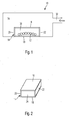
- Fig. 1 shows a schematic representation of a microwave oven 10 for the heat treatment of a dental ceramic component 12.
- the dental ceramic component is complex and large and is exemplified here. It is understood that instead of any other suitable dental ceramic components can be heat treated, for example, several components together.
- a special susceptor 14 is provided which at least partially surrounds the component 12, completely surrounding it in the illustrated embodiment.
- the susceptor 14 of the present invention is a susceptor of high purity silicon carbide in a hexagonal crystal structure, exemplifying a 4H crystal structure.
- the susceptor 14 is a single crystal with respect to the individual walls, including the floor and ceiling walls.
- the wall thickness can be kept very low, it being understood that the wall thickness can be adapted in any way to the requirements.
- the susceptor 14 is cuboid or cylindrical and closed. It has a ceiling wall 16, a bottom wall 18, a left side wall 20, a right side wall 22, a front side wall 24 and an unillustrated rear wall.
- the walls, apart from the ceiling wall 16, are connected together in any suitable manner, for example by milled-in grooves.
- the ceiling wall 16 is simply placed on top and optionally has a small bevel on the end, which lets them sink slightly into the interior 34, so that it lies captive on the side walls 20, 22, the front wall 24 and the rear wall.
- All the walls 16 to 24 are cut out of a plate which is made as a single crystal.
- Polycrystalline SiC is preferably sublimated for the preparation.
- the PVT method or modified Lely method, or any other suitable method of producing single crystal silicon carbide can be used.
- a fairly small wall thickness is provided for the realization of the susceptor 14.
- the wall thickness can also be reduced significantly below 3 mm, depending on the size of the susceptor 14.
- SiC hexagonal crystal structure of which more than 170 modifications are known in SiC
- the cubic crystal structure or zincblende structure in which the crystal is composed of two cubic face-centered lattices of different atomic species facing each other shifted by a quarter of the room diagonals.
- This SiC is also referred to as ⁇ -SiC
- the other SiC modifications either have a hexagonal or rhombohedral unit cell and are collectively referred to as ⁇ -SiC.
- ⁇ -phases occur only in the production at temperatures greater than 1,800 ° C to a significant extent, so for example in the Sublimationszüchtung with 2,000 ° C, as according to the WO 01/04389 , to which reference is made in its entirety.
- the microwave oven 10 is supplied via a non-illustrated magnetron with microwave energy, which is fed via an input 32 to the interior 34 of the microwave oven 10.
- the interior space 34 is substantially larger than the susceptor 14, for example in a volume ratio of 20: 1.
- modenrrotaryer can be provided, this is not necessary according to the invention, because despite the small wall thickness exists in ⁇ -SiC, but also in ⁇ -SiC, a superior thermal conductivity of 350 W / mK or even 400 W / mK so that on a any "hot spot" introduced microwave energy is distributed evenly quickly.
- SiC susceptor Due to the small wall thickness of the SiC susceptor on the other hand has a particularly low heat capacity, which favors a rapid heating.
- a heating curve of a microwave oven 10 according to the invention is shown in solid line, while the heating curve of a conventional microwave oven 10 is shown in dashed form.
- the heating takes place according to the invention with a maximum curve slope of 360 Kelvin / min., While a conventional microwave oven 10 to a maximum of 180 Kelvin / min. comes.
- Fig. 4 a modified heating curve is shown for a stove with lower heat capacity and correspondingly shorter cycle time. Again, it can be seen again in comparison between the solid line with the microwave oven 10 according to the invention and the dot-dash line with the conventional microwave oven, that the heating gradient is significantly improved according to the invention.
Landscapes
- Health & Medical Sciences (AREA)
- Engineering & Computer Science (AREA)
- Electromagnetism (AREA)
- Oral & Maxillofacial Surgery (AREA)
- Physics & Mathematics (AREA)
- Dentistry (AREA)
- Mechanical Engineering (AREA)
- General Engineering & Computer Science (AREA)
- Clinical Laboratory Science (AREA)
- Epidemiology (AREA)
- Life Sciences & Earth Sciences (AREA)
- Animal Behavior & Ethology (AREA)
- General Health & Medical Sciences (AREA)
- Public Health (AREA)
- Veterinary Medicine (AREA)
- Ceramic Products (AREA)
Abstract
Description
- Die Erfindung betrifft einen Mikrowellenofen, gemäß dem Oberbegriff von Anspruch 1.
- Mikrowellenöfen für die Herstellung von Stoffen und/oder Bauteilen, insbesondere keramischen Bauteilen und/oder Dentalkeramiken sind seit längerem bekannt, wobei beispielhaft auf die
EP 1 060 713 A2 verwiesen wird. Auch die Verwendung von Suszeptoren für Mikrowellen ist seit langem bekannt, beispielsweise aus derDE-OS 2 021 901 - Verschiedene Materialien, die für Mikrowellenerwärmungsgeräte verwendet werden können, sind in der
DE 37 03 163 A1 angesprochen. Der dortige Suszeptor dient zur Absorption der Mikrowellenstrahlung. - Beim Wärmebehandeln von Dentalkeramiken mittels Mikrowellen ist es wesentlich, dass die verwendeten Suszeptoren über einen breiten Bereich ankoppeln. Diese Anforderung lässt sich vergleichsweise gut mit Siliciumcarbid erfüllen, das zudem eine Temperaturfestigkeit > 2.000 °C hat, also den erwünschten Temperaturbereich für das Wärmebehandeln von Keramiken, insbesondere Dentalkeramiken, ebenfalls sicher abdeckt.
- Die bislang verwendeten Silicumcarbid-Qualitäten weisen jedoch häufig durch den Herstellungsprozess bedingte Verunreinigungen, zum Beispiel mit Vanadium oder Mangan usw., auf, die zum Beispiel Verfärbungen der wärmezubehandelnden Objekte auslösen können.
- Gerade bei grossen keramischen Bauteilen und/oder mehrgliedrigen Brücken oder größeren Dentalersatzteilen ist es wesentlich, dass eine gleichmäßige Erwärmung stattfindet und dadurch wärmeinduzierte Spannungen sowie die damit einhergehende mögliche Ausbildung von Mikrorissen in den wärmezubehandelnden Objekten verhindert werden.
- Demgegenüber liegt der Erfindung die Aufgabe zugrunde, einen Mikrowellenofen zur Wärmebehandlung von Stoffen und Bauteilen, insbesondere keramischen Bauteilen, insbesondere zum Wärmebehandeln von dentalkeramischen Bauteilen, gemäß dem Oberbegriff von Anspruch 1, bereitzustellen, der hinsichtlich der Zykluszeit verbessert ist, ohne dass Qualitätseinbußen beim fertigen Dentalrestaurationsteil zu befürchten wären.
- Diese Aufgabe wird erfindungsgemäß durch Anspruch 1 gelöst. Vorteilhafte Weiterbildungen ergeben sich aus den Unteransprüchen.
- Es wurde erkannt, dass erstaunlicherweise das Ankoppelverhalten von SiC-Einkristallen überragend besser ist als dasjenige von bisher gebräuchlichen Suszeptoren mit kommerziell erhältlichen SiC-Qualitäten. Dieses überragend bessere Kopplungsverhalten geht einher mit einer überragenden Wärmeleitfähigkeit, die dem Temperaturausgleich zwischen jeglichen in den Ofenraum eingebrachten, wärmezubehandelnden Stoffen und/oder Bauteilen, unabhängig von deren eigenem Kopplungsverhalten, dienlich ist.
- Im Gegensatz hierzu sind die in dieser Erfindung beschriebenen SiC-Qualitäten, auf Grund der Tatsache, dass sie aus nur einem Kristall Si und C bestehen, hochrein. Insbesondere weisen diese Verunreinigungen von weniger als 10-1, bevorzugt weniger als 20-2 ppm auf.
- Die Wärmeleitfähigkeit ist gegenüber dem kommerziell erhältlichen Siliciumcarbid-Bauteilen signifikant besser, was dazu führt, dass die Heizgradienten erheblich erhöht werden können, beispielsweise auch bei Bauteilen in komplexer Geometrie auf Heizraten von mehr als 400 °K/Minute. Offenbar verteilt das hochreine und bevorzugt als Einkristall vorliegende Siliciumcarbid die eingeleitete Wärme wesentlich besser, so dass keine inhomogene Wärmeverteilung mehr vorliegt.
- Insbesondere bei Bauteilen, die selbst keine gute Wärmeleitfähigkeit und/oder Eigenankopplung an die Mikrowellenstrahlung aufweisen, ist der Einsatz des beschriebenen SiC-Einkristalls als Suszeptor von Vorteil, da dieser selbst hervorragend an die Mikrowellenstrahlung ankoppelt und die entstehende Wärme in extrem kurzer Zeit sehr homogen verteilt. Durch diese Eigenschaften ist es möglich, etwaige, bei konventionellen Öfen notwendige Haltezeiten zu verkürzen und/oder, auf Grund der raschen Temperatur-Homogenisierung, schneller zu heizen, wodurch die Prozesszeiten stark verringert werden können. Dies alles kann unter Verwendung eines SiC-Einkristalls ohne die Gefahr von Wärmespannungen und Mikrorissen durchgeführt werden, also sind in kürzerer Zeit, bei mindestens gleicher, möglicherweise besserer Qualität als in der konventionellen Technik, Wärmebehandlungen von Stoffen und/oder Bauteilen durchführbar.
- Überraschend ist das Risiko von Eigendefekten und auch Verfärbungen gravierend reduziert. Da das SiC-Basismaterial aus einem Kristall aus Silicium und Kohlenstoff besteht, die durch einen Sublimationsprozess an einem SiC-Kernkristall aus der Basisphase abgeschieden werden, entstehen keine Verunreinigungsmöglichkeiten für den wärmezubehandelnden Stoff und/oder das Bauteil, insbesondere das dentalkeramische Bauteil, so dass auch Verfärbungen nicht wirklich eine Gefahr sind.
- Überraschend kann eine deutlich geringere Masse für den Suszeptor im Vergleich zu bisher verwendeten SiC-Qualitäten verwendet werden, was ein wesentlich besseres Verhältnis von Heizleistung zu Suszeptormasse mit sich bringt.
- Überraschend ergibt die Verwendung von hochreinem Siliciumcarbid in hexagonaler oder kubischer Kristallstruktur für einen Suszeptor - im Grunde nahezu unabhängig von der äußeren Form des Suszeptors - eine verbesserte Ankopplung des zu erwärmenden,Stoffs und/oder,- keramischen Bauteils. Der Suszeptorkoppelt über ein sehr breites Temperaturband sehr homogen an und gibt die aufgenommene Wärme aufgrund seiner überragenden Wärmeleitfähigkeit sofort an den wärmezubehandeinden Stoff bzw. das dentalkeramische Bauteil ab.
- Beispielsweise kann der Suszeptor einen napfförmigen Grundaufbau haben, so dass das Dentalrestaurationsteil in horizontaler Richtung allseitig von dem Suszeptor umgeben ist und gleichmäßig mit Wärme beaufschlagt wird.
- Erfindungsgemäß ist es ferner günstig, dass auch eine einseitige Beaufschlagung eines beispielsweise topfförmigen Suszeptors mit Mikrowellenstrahlung nicht zur Entstehung von nennenswerten Temperaturgradienten führt: Durch die hohe Wärmeleitfähigkeit wird auch der von der Mikrowellenquelle ferne Teil des Suszeptors umgehend erwärmt und die Problematik von etwaigen Wärmespannungen bzw. den daraus resultierenden Mikrorissen, sogar in Verbindung mit schnellerem Heizen, reduziert.
- Diese überraschende Eigenschaft führt dazu, dass der Entwickler des Mikrowellenofens eine größere gestalterische Freiheit hat: während bei den klassischen Suszeptoren bislang stets die Reflektionen der Mikrowellenstrahlung in den Raum des Mikrowellenofens genau eingeplant werden mussten, um eine möglichst gleichmäßige Mikrowellenstrahlung-Beaufschlagung des Suszeptors zu erzielen, gilt dies nun nicht mehr. Sowohl im Monomode- als auch im Mutimode-Betrieb lassen sich die erwünschte Temperaturvergleichmässigung und eine robuste Anpassung der (Ofen-) Anlage ohne weiteres bereitstellen.
- In vorteilhafter Ausgestaltung weist der Kristall-Suszeptor eine glatte und optisch ansprechende Oberfläche auf. Dies hat gegenüber einer Mikropunktauflage, wie sie zum Beispiel bei gesinterten Siliciumcarbidkörpern entsteht, auch den besonderen Vorteil, dass eine großflächige Auflage möglich ist, die den Wärmeübergangswiderstand zwischen dem Suszeptor und dem Dentalrestaurationsteil verbessert.
- Es versteht sich, dass die Form des oder der erfindungsgemäßen Kristall-Suszeptoren in weiten Bereichen an die Erfordernisse anpassbar ist. Beispielsweise können auch Suszeptorkörper bereitgestellt werden, die je einzeln in dichtester Kugelpackung angeordnet sind, als Kristall-Suszeptoren ausgebildet sind und das wärmezubehandeinde Objekt eng anliegend umgeben.
- Erfindungsgemäß ist es besonders günstig, dass zur Wärmebehandlung von Stoffen und/oder Bauteilen, besonders von keramischen Bauteilen, insbesondere von dentalkeramischen Bauteilen, mit einem Suszeptor, der im Wellengang oder in dem mit Mikrowellenstrahlung beaufschlagten Bereich zwischen einer Mikrowellenquelle und dem Bauteil angeordnet ist, dadurch gekennzeichnet, dass der Suszeptor aus hochreinem Siliciumcarbid in hexagonaler, rhomboedrischer oder kubischer Kristallstruktur, insbesondere in 2H-, 4H-, 6H- oder 3C-Kristallstruktur, aufweist.
- Gemäß einer vorteilhaften Ausgestaltung ist es vorgesehen, dass es sich bei dem Siliciumcarbid um einen Einkristall handelt.
- Gemäß einer vorteilhaften Ausgestaltung ist es vorgesehen, dass das Bauteil an Mikrowellenstrahlungen breitbandig, insbesondere über ein Band von mehr als 10 % der Mikrowellen-Grundfrequenz der verwendeten Mikrowellenquelle, ankoppelt, insbesondere bereits bei Raumtemperatur und/oder bei 0°C und auch bei der für das Sintern von Dentalkeramiken höchsten verwendeten Temperatur, insbesondere auch bei 2000°C.
- Gemäß einer vorteilhaften Ausgestaltung ist es vorgesehen, dass der Mikrowellenofen eine für den Monomoden- oder für den Multimoden-Betrieb geeignete Kavität aufweist.
- Gemäß einer vorteilhaften Ausgestaltung ist es vorgesehen, dass der Suszeptor gegenüber dem Stoff und/oder dem keramischen Bauteil inert oder nicht-reaktiv, insbesondere an seiner Oberfläche, ausgestaltet ist und bei Anlage auch bei hohen Temperaturen eine chemische Reaktion zwischen Bauteil und Suszeptor vermieden wird.
- Gemäß einer vorteilhaften Ausgestaltung ist es vorgesehen dass der Suszeptor eine Wärmeleitfähigkeit >200 W/mK aufweist, insbesondere etwa 350 W/mK.
- Gemäß einer vorteilhaften Ausgestaltung ist es vorgesehen, dass der Suszeptor eine geometrische Ausbildung in Ring-, Scheiben- oder sonstigen geometrischen Formen besitzt und in direktem Kontakt bzw. in unmittelbarer Nähe zum wärmezubehandelnden Bauteil und/oder Stoff steht.
- Gemäß einer vorteilhaften Ausgestaltung ist es vorgesehen, dass ein maximaler Abstand des Suszeptors zu dem Stoff oder Bauteil < 5 cm beträgt.
- Gemäß einer vorteilhaften Ausgestaltung ist es vorgesehen, dass der Mikrowellenofen einen geschlossenen Innenraum aufweist, der mit der Mikrowellenquelle in Wellenverbindung steht, wobei die Mikrowellenquelle die einzige Wärmequelle ist.
- Gemäß einer vorteilhaften Ausgestaltung ist es vorgesehen, dass der Mikrowellenofen eine zusätzliche Wärmequelle, insbesondere eine Infrarot-strahlende Wärmequelle aufweist, die den Suszeptor und/oder das Bauteil oder den Stoff mit Wärmeenergie beaufschlagt.
- Gemäß einer vorteilhaften Ausgestaltung ist es vorgesehen, dass ein optischer Temperaturmesssensor auf eine Suszeptoroberfläche gerichtet ist, insbesondere auf eine dem Bauteil zugewandte Suszeptoroberfläche, wenn ein offener Suszeptor eingesetzt ist, und die Temperatur des Bauteils basierend auf der Oberfläche des Suszeptors erfasst.
- Gemäß einer vorteilhaften Ausgestaltung ist es vorgesehen, dass der Stoff oder das Bauteil nicht selbst-koppelnd für Mikrowellenstrahlung ist und seine Erwärmung vollständig durch Wärmeabgabe des Suszeptors erfährt.
- Gemäß einer vorteilhaften Ausgestaltung ist es vorgesehen, dass der Stoff oder das Bauteil selbständig koppelnd für Mikrowellenstrahlung ist und der Suszeptor als Grundlast-Mikrowellensenke ausgebildet ist und ein vorgegebenes Maß an Mikrowellenstrahlung absorbiert und insbesondere eine gleichmäßige Temperaturverteilung, frei von Hot Spots, bewirkt.
- Gemäß einer vorteilhaften Ausgestaltung ist es vorgesehen, dass der Innenraum des Mikrowellenofens gasdicht abgeschlossen ist und unter Über- oder Unterdruck setzbar ist, und insbesondere mit einem Spülgas spülbar ist und besonders bevorzugt als offener oder geschlossener Durchlaufofen ausgebildet ist.
- Gemäß einer vorteilhaften Ausgestaltung ist es vorgesehen, dass der Suszeptor die Kopplung der keramischen Bauteile an die elektromagnetische Strahlung verhindert und abschirmt und insbesondere weniger als 10% der eintreffenden elektromagnetischen Strahlung zum Bauteil durchlässt.
- Gemäß einer vorteilhaften Ausgestaltung ist es vorgesehen, dass der Suszeptor eine glatte, optisch ansprechende Oberfläche aufweist.
- Weitere Vorteile, Einzelheiten und Merkmale ergeben sich aus der nachstehenden Beschreibung eines Ausführungsbeispiels der Erfindung anhand der Zeichnung.
- Es zeigen:
- Fig. 1
- eine schematische Ansicht eines Mikrowellenofens in einer möglichen Ausführungsform der Erfindung;
- Fig. 2
- eine schematische Ansicht, der erfindungsgemäß hergestellt ist, in der Ausführungsform gemäß
Fig. 1 ; - Fig. 3
- ein Diagramm für den Vergleich der Aufheizkurve eines erfindungsgemäßen Mikrowellenofens in der Ausführungsform gemäß
Fig. 1 ; und - Fig. 4
- eine andere Aufheizkurve des erfindungsgemäßen Mikrowellenofens, im Vergleich mit einem mit konventionell erhältlichen SiC betriebenen Mikrowellenofen.
-
Fig. 1 zeigt in schematischer Darstellung einen Mikrowellenofen 10 für die Wärmebehandlung eines dentalkeramischen Bauteils 12. Wie ersichtlich ist, ist das dentalkeramische Bauteil komplex und groß und ist hier beispielhaft aufgeführt. Es versteht sich, dass anstelle dessen auch beliebiger anderer geeigneter dentalkeramischer Bauteile wärmebehandelt werden können, auch beispielsweise mehrere Bauteile gemeinsam. - Erfindungsgemäß ist ein besonderer Suszeptor 14 vorgesehen, der das Bauteil 12 mindestens teilweise umgibt, im dargestellten Ausführungsbeispiel vollständig umgibt.
- Der erfindungsgemäße Suszeptor 14 ist ein Suszeptor aus hochreinem Siliciumcarbid in hexagonaler Kristallstruktur, wobei beispielhaft eine 4H-Kristallstruktur vorgesehen ist.
- Es versteht sich, dass anstelle dessen auch ohne weiteres eine 2H- oder eine 6H-Kristallstruktur realisiert werden kann, oder eine kubische 3C-Kristallstruktur.
- Bevorzugt handelt es sich bei dem Suszeptor 14 hinsichtlich der einzelnen Wände, auch der Boden- und Deckenwände, je um ein Einkristall.
- Der Suszeptor 14, der auch in
Fig. 2 perspektivisch dargestellt ist, besteht fertigunstechnisch bedingt aus einzelnen plattenförmigen Wänden. Bei der Auslegung des Suszeptors kann die Wandstärke sehr gering gehalten werden, wobei es sich versteht, dass die Wandstärke in beliebiger Weise an die Erfordernisse anpassbar ist. - In dem dargestellten Ausführungsbeispiel ist der Suszeptor 14 quaderförmig oder zylinderörmig und geschlossen. Er weist eine Deckenwand 16, eine Bodenwand 18, eine linke Seitenwand 20, eine rechte Seitenwand 22, eine vordere Seitenwand 24 sowie eine nicht ersichtliche Rückwand auf.
- Anstelle dessen ist auch eine offene Bauweise ohne die Deckenwand 16 möglich.
- Die Wände, abgesehen von der Deckenwand 16, sind in beliebiger geeigneter Weise, beispielsweise durch eingefräste Nuten, miteinander verbunden. Die Deckenwand 16 ist hingegen einfach aufgelegt und weist gegebenenfalls endseitig eine kleine Abschrägung auf, die sie etwas in den Innenraum 34 einsinken lässt, so dass sie unverlierbar auf den Seitenwänden 20, 22, der Vorderwand 24 und der Rückwand aufliegt.
- Sämtliche Wände 16 bis 24 sind aus einer Platte ausgeschnitten, die als Einkristall hergestellt ist. Für die Herstellung wird bevorzugt polykristallines SiC sublimiert. Es kann das PVT-Verfahren eingesetzt werden oder die modifizierte Lely-Methode, oder ein beliebiges anderes, geeignetes Verfahren zur Erzeugung von einkristallinem Silicumcarbid.
- Es ist auch möglich, den Einkristall durch Chemical Vapor Deposition epitaxial zu erzeugen. Ein mögliches Verfahren ist in der
WO 01/04389 - Es versteht sich, dass auch beliebige andere Formen für die Herstellung eines mindestens teilweise geschlossenen Suszeptors 14 realisierbar sind. Für die Realisierung mittels Einkristallen ist jedoch die Verwendung von planen Wänden günstig.
- Wie ersichtlich ist, ist eine recht geringe Wandstärke für die Realisierung des Suszeptors 14 vorgesehen. Die Wandstärke kann auch deutlich unter 3 mm reduziert werden, je nach Größe des Suszeptors 14.
- Während bevorzugt eine hexagonale Kristallstruktur verwendet wird, von der bei SiC mehr als 170 Modifikationen bekannt sind, ist es auch möglich, die kubische Kristallstruktur oder Zinkblende-Struktur zu verwenden, bei der der Kristall aus zwei kubisch flächenzentrierten Gittern verschiedener Atomsorten aufgebaut ist, die gegeneinander um ein Viertel der Raumdiagonalen verschoben sind. Dieses SiC wird auch als β-SiC bezeichnet, während die anderen SiC-Modifikationen entweder eine hexagonale oder rhomboedrische Einheitszelle aufweisen und zusammenfassend als α-SiC bezeichnet werden. α-Phasen treten erst bei der Erzeugung mit Temperaturen mit mehr als 1.800 °C in nennenswertem Umfang auf, also beispielsweise bei der Sublimationszüchtung mit 2.000 °C, wie sie gemäß der
WO 01/04389 - In an sich bekannter Weise wird der Mikrowellenofen 10 über ein nicht dargestelltes Magnetron mit Mikrowellenenergie versorgt, die über einem Eingang 32 dem Innenraum 34 des Mikrowellenofens 10 zugeleitet wird. Der Innenraum 34 ist wesentlich größer als der Suszeptor 14, beispielsweise in einem Volumenverhältnis von 20:1. Auch wenn Modenrührer vorgesehen sein können, ist dies erfindungsgemäß nicht nötig, denn trotz der geringen Wandstärke besteht bei α-SiC, aber auch bei β-SiC, eine überragende Wärmeleitfähigkeit von 350 W/mK oder gar 400 W/mK so dass die an einem etwaigen "Hot Spot" eingeleitete Mikrowellenenergie sich rasch gleichmäßig verteilt.
- Durch die geringe Wandstärke hat der SiC-Suszeptor andererseits eine besonders geringe Wärmekapazität, was eine schnelle Aufheizung begünstigt.
- Gemäß
Fig. 3 ist eine Aufheizkurve eines erfindungsgemäßen Mikrowellenofens 10 in durchgezogener Linie dargestellt, während die Aufheizkurve eines konventionellen Mikrowellenofens 10 in gestrichelter Form dargestellt ist. Die Aufheizung erfolgt erfindungsgemäß mit einer maximalen Kurvenneigung von 360 Kelvin/Min., während ein üblicher Mikrowellenofen 10 auf maximal 180 Kelvin/Min. kommt. - In
Fig. 4 ist eine modifizierte Aufheizkurve für einen Ofen mit geringerer Wärmekapazität und dementsprechend geringerer Zykluszeit dargestellt. Auch hier ist wiederum im Vergleich zwischen der durchgezogenen Linie mit dem erfindungsgemäßen Mikrowellenofen 10 und der strichpunktierten Linie mit dem konventionellen Mikrowellenofen ersichtlich, dass der Aufheizgradient erfindungsgemäß deutlich verbessert ist.
Claims (15)
- Mikrowellenofen, zur Wärmebehandlung von Stoffen und/oder Bauteilen, besonders von keramischen Bauteilen, insbesondere von dentalkeramischen Bauteilen, mit einem Suszeptor (14), der im Wellengang oder in dem mit Mikrowellenstrahlung beaufschlagten Bereich zwischen einer Mikrowellenquelle und dem Bauteil angeordnet ist, dadurch gekennzeichnet, dass der Suszeptor (14) aus hochreinem Siliciumcarbid in hexagonaler, rhomboedrischer oder kubischer Kristallstruktur, insbesondere in 2H-, 4H-, 6H-oder 3C-Kristallstruktur, aufweist.
- Mikrowellenofen nach Anspruch 1, dadurch gekennzeichnet, dass es sich bei dem Siliciumcarbid um einen Einkristall handelt.
- Mikrowellenofen nach Anspruch 1 oder 2, dadurch gekennzeichnet, dass das Bauteil (12) an Mikrowellenstrahlungen breitbandig, insbesondere über ein Band von mehr als 10 % der Mikrowellen-Grundfrequenz der verwendeten Mikrowellenquelle, ankoppelt, insbesondere bereits bei Raumtemperatur und/oder bei 0°C und auch bei der für das Sintern von Dentalkeramiken höchsten verwendeten Temperatur, insbesondere auch bei 2000°C.
- Mikrowellenofen nach einem der vorhergehenden Ansprüche, dadurch gekennzeichnet, dass der Mikrowellenofen (10) eine für den Monomoden- oder für den Multimoden-Betrieb geeignete Kavität aufweist.
- Mikrowellenofen nach einem der vorhergehenden Ansprüche, dadurch gekennzeichnet, dass der Suszeptor (14) gegenüber dem Stoff und/oder dem keramischen Bauteil (12) inert oder nicht-reaktiv, insbesondere an seiner Oberfläche, ausgestaltet ist und bei Anlage auch bei hohen Temperaturen eine chemische Reaktion zwischen Bauteil (12) und Suszeptor (14) vermieden wird.
- Mikrowellenofen, dadurch gekennzeichnet, dass der Suszeptor (14) eine Wärmeleitfähigkeit >200 W/mK aufweist, insbesondere etwa 350 W/mK.
- Mikrowellenofen nach einem der vorhergehenden Ansprüche, dadurch gekennzeichnet, dass der Suszeptor (14) eine geometrische Ausbildung in Ring-, Scheiben- oder sonstigen geometrischen Formen besitzt und in direktem Kontakt bzw. in unmittelbarer Nähe zum wärmezubehandelnden Bauteil und/oder Stoff steht.
- Mikrowellenofen nach einem der vorhergehenden Ansprüche, dadurch gekennzeichnet, dass ein maximaler Abstand des Suszeptors (14) zu dem Stoff oder Bauteil < 5 cm beträgt.
- Mikrowellenofen nach einem der vorhergehenden Ansprüche, dadurch gekennzeichnet, dass der Mikrowellenofen (10) einen geschlossenen Innenraum (34) aufweist, der mit der Mikrowellenquelle (32) in Wellenverbindung steht, wobei die Mikrowellenquelle die einzige Wärmequelle ist.
- Mikrowellenofen nach einem der Ansprüche 1 bis 8, dadurch gekennzeichnet, dass der Mikrowellenofen (10) eine zusätzliche Wärmequelle, insbesondere eine Infrarot-strahlende Wärmequelle aufweist, die den Suszeptor (14) und/oder das Bauteil oder den Stoff mit Wärmeenergie beaufschlagt.
- Mikrowellenofen nach einem der vorhergehenden Ansprüche, dadurch gekennzeichnet, dass ein optischer Temperaturmesssensor auf eine Suszeptoroberfläche gerichtet ist, insbesondere auf eine dem Bauteil (12) zugewandte Suszeptoroberfläche, wenn ein offener Suszeptor eingesetzt ist, und die Temperatur des Bauteils basierend auf der Oberfläche des Suszeptors (14) erfasst.
- Mikrowellenofen nach einem der vorhergehenden Ansprüche, dadurch gekennzeichnet, dass der Stoff oder das Bauteil nicht selbst-koppelnd für Mikrowellenstrahlung ist und seine Erwärmung vollständig durch Wärmeabgabe des Suszeptors (14) erfährt.
- Mikrowellenofen nach einem der Ansprüche 1 bis 11, dadurch gekennzeichnet, dass der Stoff oder das Bauteil selbständig koppelnd für Mikrowellenstrahlung ist und der Suszeptor (14) als Grundlast-Mikrowellensenke ausgebildet ist und ein vorgegebenes Maß an Mikrowellenstrahlung absorbiert und insbesondere eine gleichmäßige Temperaturverteilung, frei von Hot Spots, bewirkt.
- Mikrowellenofen nach einem der vorhergehenden Ansprüche, dadurch gekennzeichnet, dass der Innenraum (34) des Mikrowellenofens (10) gasdicht abgeschlossen ist und unter Über- oder Unterdruck setzbar ist, und insbesondere mit einem Spülgas spülbar ist und besonders bevorzugt als offener oder geschlossener Durchlaufofen ausgebildet ist.
- Suszeptor für einen Mikrowellenofen (10), gekennzeichnet durch die kennzeichnenden Merkmale eines der vorhergehenden Ansprüche.
Priority Applications (3)
| Application Number | Priority Date | Filing Date | Title |
|---|---|---|---|
| EP10186238.1A EP2437020B1 (de) | 2010-10-01 | 2010-10-01 | Mikrowellenofen |
| US13/244,968 US9228782B2 (en) | 2010-10-01 | 2011-09-26 | Microwave oven |
| JP2011218791A JP5775411B2 (ja) | 2010-10-01 | 2011-09-30 | マイクロ波オーブン |
Applications Claiming Priority (1)
| Application Number | Priority Date | Filing Date | Title |
|---|---|---|---|
| EP10186238.1A EP2437020B1 (de) | 2010-10-01 | 2010-10-01 | Mikrowellenofen |
Publications (2)
| Publication Number | Publication Date |
|---|---|
| EP2437020A1 true EP2437020A1 (de) | 2012-04-04 |
| EP2437020B1 EP2437020B1 (de) | 2015-08-12 |
Family
ID=43608375
Family Applications (1)
| Application Number | Title | Priority Date | Filing Date |
|---|---|---|---|
| EP10186238.1A Not-in-force EP2437020B1 (de) | 2010-10-01 | 2010-10-01 | Mikrowellenofen |
Country Status (3)
| Country | Link |
|---|---|
| US (1) | US9228782B2 (de) |
| EP (1) | EP2437020B1 (de) |
| JP (1) | JP5775411B2 (de) |
Cited By (1)
| Publication number | Priority date | Publication date | Assignee | Title |
|---|---|---|---|---|
| WO2016156275A1 (fr) * | 2015-03-27 | 2016-10-06 | Centre National De La Recherche Scientifique | Procédé de traitement thermique de revêtement de surface sur une pièce métallique par micro-ondes |
Families Citing this family (6)
| Publication number | Priority date | Publication date | Assignee | Title |
|---|---|---|---|---|
| DE102008035235B4 (de) * | 2008-07-29 | 2014-05-22 | Ivoclar Vivadent Ag | Vorrichtung zur Erwärmung von Formteilen, insbesondere dentalkeramischen Formteilen |
| DE102008035240B4 (de) * | 2008-07-29 | 2017-07-06 | Ivoclar Vivadent Ag | Vorrichtung zur Erwärmung von Formteilen, insbesondere dentalkeramischen Formteilen |
| US9759487B2 (en) | 2011-03-02 | 2017-09-12 | Ivoclar Vivadent Ag | Dental firing or press furnace |
| ES2528005T3 (es) * | 2011-03-02 | 2015-02-03 | Ivoclar Vivadent Ag | Horno dental de cocción o de prensado |
| US9540279B2 (en) * | 2013-05-24 | 2017-01-10 | Corning Incorporated | Method of producing glass-ceramic |
| JP6877433B2 (ja) * | 2015-12-16 | 2021-05-26 | スリーエム イノベイティブ プロパティズ カンパニー | マイクロ波炉及び焼結方法 |
Citations (6)
| Publication number | Priority date | Publication date | Assignee | Title |
|---|---|---|---|---|
| DE2021901A1 (de) | 1969-05-05 | 1970-11-19 | Gen Electric | Hochfrequenz-Induktionsheizungsanlage |
| DE3703163A1 (de) | 1986-02-04 | 1987-08-06 | Commercial Decal Inc | Mikrowellenerwaermungs-geraet und abziehbild |
| JPH11106283A (ja) | 1997-10-01 | 1999-04-20 | Kyocera Corp | ルツボ用サセプタ |
| EP1060713A1 (de) | 1999-06-17 | 2000-12-20 | Wieland Edelmetalle GmbH & Co. | Verfahren zur Herstellung von Dentalkeramiken sowie Ofen zur Wärmebehandlung von Dentalkeramiken |
| WO2009039220A1 (en) | 2007-09-17 | 2009-03-26 | Dsgi, Inc. | System for and method of microwave annealing semiconductor material |
| EP2150092A2 (de) | 2008-07-29 | 2010-02-03 | Ivoclar Vivadent AG | Vorrichtung zur Erwärmung von Formteilen, insbesondere dentalkeramischen Formteilen |
Family Cites Families (10)
| Publication number | Priority date | Publication date | Assignee | Title |
|---|---|---|---|---|
| US5432325A (en) * | 1994-10-20 | 1995-07-11 | University Of California | Microwave sintering of single plate-shaped articles |
| JPH08261474A (ja) * | 1995-03-17 | 1996-10-11 | Chichibu Onoda Cement Corp | 電子レンジ調理用マイクロ波吸収発熱体及びその製造方法 |
| DE19515342A1 (de) * | 1995-04-26 | 1996-10-31 | Widia Gmbh | Verfahren, Vorrichtung zur thermischen Behandlung von Stoffen in einem Mikrowellenofen und Verwendung dieses Verfahrens und dieser Vorrichtung |
| JP4551143B2 (ja) * | 2004-07-09 | 2010-09-22 | 新日本製鐵株式会社 | マイクロ波発熱体およびその製造方法 |
| US7161126B2 (en) * | 2004-11-10 | 2007-01-09 | Bwxt Y-12, Llc | Microwave heat treating of manufactured components |
| GB0505752D0 (en) * | 2005-03-21 | 2005-04-27 | Element Six Ltd | Diamond based substrate for gan devices |
| US20070235450A1 (en) * | 2006-03-30 | 2007-10-11 | Advanced Composite Materials Corporation | Composite materials and devices comprising single crystal silicon carbide heated by electromagnetic radiation |
| US20090079101A1 (en) * | 2007-04-27 | 2009-03-26 | Jurgen Laubersheimer | Densification Process of Ceramics And Apparatus Therefor |
| US8226770B2 (en) * | 2007-05-04 | 2012-07-24 | Applied Materials, Inc. | Susceptor with backside area of constant emissivity |
| JP2010182476A (ja) * | 2009-02-04 | 2010-08-19 | Taiheiyo Cement Corp | 発熱体および加熱装置 |
-
2010
- 2010-10-01 EP EP10186238.1A patent/EP2437020B1/de not_active Not-in-force
-
2011
- 2011-09-26 US US13/244,968 patent/US9228782B2/en active Active
- 2011-09-30 JP JP2011218791A patent/JP5775411B2/ja not_active Expired - Fee Related
Patent Citations (6)
| Publication number | Priority date | Publication date | Assignee | Title |
|---|---|---|---|---|
| DE2021901A1 (de) | 1969-05-05 | 1970-11-19 | Gen Electric | Hochfrequenz-Induktionsheizungsanlage |
| DE3703163A1 (de) | 1986-02-04 | 1987-08-06 | Commercial Decal Inc | Mikrowellenerwaermungs-geraet und abziehbild |
| JPH11106283A (ja) | 1997-10-01 | 1999-04-20 | Kyocera Corp | ルツボ用サセプタ |
| EP1060713A1 (de) | 1999-06-17 | 2000-12-20 | Wieland Edelmetalle GmbH & Co. | Verfahren zur Herstellung von Dentalkeramiken sowie Ofen zur Wärmebehandlung von Dentalkeramiken |
| WO2009039220A1 (en) | 2007-09-17 | 2009-03-26 | Dsgi, Inc. | System for and method of microwave annealing semiconductor material |
| EP2150092A2 (de) | 2008-07-29 | 2010-02-03 | Ivoclar Vivadent AG | Vorrichtung zur Erwärmung von Formteilen, insbesondere dentalkeramischen Formteilen |
Cited By (2)
| Publication number | Priority date | Publication date | Assignee | Title |
|---|---|---|---|---|
| WO2016156275A1 (fr) * | 2015-03-27 | 2016-10-06 | Centre National De La Recherche Scientifique | Procédé de traitement thermique de revêtement de surface sur une pièce métallique par micro-ondes |
| US10882071B2 (en) | 2015-03-27 | 2021-01-05 | Centre National De La Recherche Scientifique | Method for thermal treatment of a surface coating on a metal part by microwaves |
Also Published As
| Publication number | Publication date |
|---|---|
| JP5775411B2 (ja) | 2015-09-09 |
| EP2437020B1 (de) | 2015-08-12 |
| US20120080425A1 (en) | 2012-04-05 |
| US9228782B2 (en) | 2016-01-05 |
| JP2012075902A (ja) | 2012-04-19 |
Similar Documents
| Publication | Publication Date | Title |
|---|---|---|
| EP2437020B1 (de) | Mikrowellenofen | |
| EP2098188B1 (de) | Verfahren zum Sintern eines Dentalmaterials | |
| EP3256804B1 (de) | Sinterofen für bauteile aus sinterwerkstoff, insbesondere dentalbauteile | |
| WO2010085949A2 (de) | Substratträger zur halterung von substraten | |
| DE102007004242B4 (de) | Verfahren zum Herstellen eines Formkörpers aus Quarzglas durch Sintern, Formkörper und Verwendung des Formkörpers | |
| EP2452651A1 (de) | Dentalofen mit Suszeptor-Behälter | |
| WO2011101327A1 (de) | Verfahren zur herstellung eines quarzglastiegels | |
| DE112014002183T5 (de) | Verfahren zur Herstellung eines Silizium-Einkristalls | |
| DE102008035240B4 (de) | Vorrichtung zur Erwärmung von Formteilen, insbesondere dentalkeramischen Formteilen | |
| DE102008035235B4 (de) | Vorrichtung zur Erwärmung von Formteilen, insbesondere dentalkeramischen Formteilen | |
| DE202021102935U1 (de) | Kristallzüchtungsanlage zur Herstellung eines Einkristalls | |
| DE4438398C2 (de) | Wärmebehandlungsverfahren für Verbindungshalbleiter und Verwendung eines Suszeptors in der Wärmebehandlung | |
| EP1152641A2 (de) | Mikrowellenofen zum Aufheizen von Brenngut | |
| DE102011012363A1 (de) | Infrarot-Flächenstrahler mit hoher Strahlungsleistung und Verfahren für seine Herstellung | |
| EP2067754B1 (de) | Verfahren zur herstellung einer polykristallinen transparenten kermaik durch zyklisches pressen | |
| DE19912484A1 (de) | Vorrichtung zur Herstellung von Einkristallen | |
| WO2000078243A1 (de) | Verfahren zur herstellung von dentalkeramiken sowie ofen zur wärmebehandlung von dentalkeramiken | |
| DE69913906T2 (de) | Lichtundurchlässiger Siliziumkarbidwerkstoff hoher Reinheit, ein lichtundurchlässiger Bauteil für eine Halbleiterbehandlungsapparatur, und eine Halbleiterbehandlungsapparatur | |
| DE102019109551B4 (de) | Wärmeisolierendes abschirmungselement und einkristall-herstellungsvorrichtung, welche dieses aufweist | |
| DE102010011156B4 (de) | Vorrichtung zur thermischen Behandlung von Halbleitersubstraten | |
| DE19734736B4 (de) | Behälter aus pyrolytischem Bornitrid | |
| EP2609613B1 (de) | Verfahren und vorrichtung zum behandeln eines substrats mittels eines plasmas | |
| AT524602B1 (de) | Vorrichtung zur Herstellung eines Einkristalls | |
| DE102012003903A1 (de) | Verfahren zur thermischen Behandlung von Siliziumcarbidsubstraten | |
| DE102020104226A1 (de) | Verfahren zur Herstellung eines Einkristalls in einem Wachstumstiegel |
Legal Events
| Date | Code | Title | Description |
|---|---|---|---|
| PUAI | Public reference made under article 153(3) epc to a published international application that has entered the european phase |
Free format text: ORIGINAL CODE: 0009012 |
|
| AK | Designated contracting states |
Kind code of ref document: A1 Designated state(s): AL AT BE BG CH CY CZ DE DK EE ES FI FR GB GR HR HU IE IS IT LI LT LU LV MC MK MT NL NO PL PT RO RS SE SI SK SM TR |
|
| AX | Request for extension of the european patent |
Extension state: BA ME |
|
| 17P | Request for examination filed |
Effective date: 20121004 |
|
| 17Q | First examination report despatched |
Effective date: 20130226 |
|
| GRAP | Despatch of communication of intention to grant a patent |
Free format text: ORIGINAL CODE: EPIDOSNIGR1 |
|
| INTG | Intention to grant announced |
Effective date: 20150323 |
|
| GRAS | Grant fee paid |
Free format text: ORIGINAL CODE: EPIDOSNIGR3 |
|
| GRAA | (expected) grant |
Free format text: ORIGINAL CODE: 0009210 |
|
| AK | Designated contracting states |
Kind code of ref document: B1 Designated state(s): AL AT BE BG CH CY CZ DE DK EE ES FI FR GB GR HR HU IE IS IT LI LT LU LV MC MK MT NL NO PL PT RO RS SE SI SK SM TR |
|
| REG | Reference to a national code |
Ref country code: GB Ref legal event code: FG4D Free format text: NOT ENGLISH |
|
| REG | Reference to a national code |
Ref country code: CH Ref legal event code: EP |
|
| REG | Reference to a national code |
Ref country code: AT Ref legal event code: REF Ref document number: 742546 Country of ref document: AT Kind code of ref document: T Effective date: 20150815 |
|
| REG | Reference to a national code |
Ref country code: IE Ref legal event code: FG4D Free format text: LANGUAGE OF EP DOCUMENT: GERMAN |
|
| REG | Reference to a national code |
Ref country code: CH Ref legal event code: NV Representative=s name: KELLER AND PARTNER PATENTANWAELTE AG, CH |
|
| REG | Reference to a national code |
Ref country code: DE Ref legal event code: R096 Ref document number: 502010010035 Country of ref document: DE |
|
| REG | Reference to a national code |
Ref country code: FR Ref legal event code: PLFP Year of fee payment: 6 |
|
| REG | Reference to a national code |
Ref country code: SE Ref legal event code: TRGR |
|
| REG | Reference to a national code |
Ref country code: LT Ref legal event code: MG4D |
|
| REG | Reference to a national code |
Ref country code: NL Ref legal event code: MP Effective date: 20150812 |
|
| PG25 | Lapsed in a contracting state [announced via postgrant information from national office to epo] |
Ref country code: NO Free format text: LAPSE BECAUSE OF FAILURE TO SUBMIT A TRANSLATION OF THE DESCRIPTION OR TO PAY THE FEE WITHIN THE PRESCRIBED TIME-LIMIT Effective date: 20151112 Ref country code: LV Free format text: LAPSE BECAUSE OF FAILURE TO SUBMIT A TRANSLATION OF THE DESCRIPTION OR TO PAY THE FEE WITHIN THE PRESCRIBED TIME-LIMIT Effective date: 20150812 Ref country code: FI Free format text: LAPSE BECAUSE OF FAILURE TO SUBMIT A TRANSLATION OF THE DESCRIPTION OR TO PAY THE FEE WITHIN THE PRESCRIBED TIME-LIMIT Effective date: 20150812 Ref country code: GR Free format text: LAPSE BECAUSE OF FAILURE TO SUBMIT A TRANSLATION OF THE DESCRIPTION OR TO PAY THE FEE WITHIN THE PRESCRIBED TIME-LIMIT Effective date: 20151113 Ref country code: LT Free format text: LAPSE BECAUSE OF FAILURE TO SUBMIT A TRANSLATION OF THE DESCRIPTION OR TO PAY THE FEE WITHIN THE PRESCRIBED TIME-LIMIT Effective date: 20150812 |
|
| PG25 | Lapsed in a contracting state [announced via postgrant information from national office to epo] |
Ref country code: PL Free format text: LAPSE BECAUSE OF FAILURE TO SUBMIT A TRANSLATION OF THE DESCRIPTION OR TO PAY THE FEE WITHIN THE PRESCRIBED TIME-LIMIT Effective date: 20150812 Ref country code: IS Free format text: LAPSE BECAUSE OF FAILURE TO SUBMIT A TRANSLATION OF THE DESCRIPTION OR TO PAY THE FEE WITHIN THE PRESCRIBED TIME-LIMIT Effective date: 20151212 Ref country code: ES Free format text: LAPSE BECAUSE OF FAILURE TO SUBMIT A TRANSLATION OF THE DESCRIPTION OR TO PAY THE FEE WITHIN THE PRESCRIBED TIME-LIMIT Effective date: 20150812 Ref country code: HR Free format text: LAPSE BECAUSE OF FAILURE TO SUBMIT A TRANSLATION OF THE DESCRIPTION OR TO PAY THE FEE WITHIN THE PRESCRIBED TIME-LIMIT Effective date: 20150812 Ref country code: RS Free format text: LAPSE BECAUSE OF FAILURE TO SUBMIT A TRANSLATION OF THE DESCRIPTION OR TO PAY THE FEE WITHIN THE PRESCRIBED TIME-LIMIT Effective date: 20150812 Ref country code: PT Free format text: LAPSE BECAUSE OF FAILURE TO SUBMIT A TRANSLATION OF THE DESCRIPTION OR TO PAY THE FEE WITHIN THE PRESCRIBED TIME-LIMIT Effective date: 20151214 |
|
| PG25 | Lapsed in a contracting state [announced via postgrant information from national office to epo] |
Ref country code: NL Free format text: LAPSE BECAUSE OF FAILURE TO SUBMIT A TRANSLATION OF THE DESCRIPTION OR TO PAY THE FEE WITHIN THE PRESCRIBED TIME-LIMIT Effective date: 20150812 |
|
| PG25 | Lapsed in a contracting state [announced via postgrant information from national office to epo] |
Ref country code: CZ Free format text: LAPSE BECAUSE OF FAILURE TO SUBMIT A TRANSLATION OF THE DESCRIPTION OR TO PAY THE FEE WITHIN THE PRESCRIBED TIME-LIMIT Effective date: 20150812 Ref country code: SK Free format text: LAPSE BECAUSE OF FAILURE TO SUBMIT A TRANSLATION OF THE DESCRIPTION OR TO PAY THE FEE WITHIN THE PRESCRIBED TIME-LIMIT Effective date: 20150812 Ref country code: DK Free format text: LAPSE BECAUSE OF FAILURE TO SUBMIT A TRANSLATION OF THE DESCRIPTION OR TO PAY THE FEE WITHIN THE PRESCRIBED TIME-LIMIT Effective date: 20150812 Ref country code: EE Free format text: LAPSE BECAUSE OF FAILURE TO SUBMIT A TRANSLATION OF THE DESCRIPTION OR TO PAY THE FEE WITHIN THE PRESCRIBED TIME-LIMIT Effective date: 20150812 |
|
| REG | Reference to a national code |
Ref country code: DE Ref legal event code: R097 Ref document number: 502010010035 Country of ref document: DE |
|
| PG25 | Lapsed in a contracting state [announced via postgrant information from national office to epo] |
Ref country code: RO Free format text: LAPSE BECAUSE OF FAILURE TO SUBMIT A TRANSLATION OF THE DESCRIPTION OR TO PAY THE FEE WITHIN THE PRESCRIBED TIME-LIMIT Effective date: 20150812 Ref country code: LU Free format text: LAPSE BECAUSE OF FAILURE TO SUBMIT A TRANSLATION OF THE DESCRIPTION OR TO PAY THE FEE WITHIN THE PRESCRIBED TIME-LIMIT Effective date: 20151001 |
|
| PLBE | No opposition filed within time limit |
Free format text: ORIGINAL CODE: 0009261 |
|
| STAA | Information on the status of an ep patent application or granted ep patent |
Free format text: STATUS: NO OPPOSITION FILED WITHIN TIME LIMIT |
|
| PG25 | Lapsed in a contracting state [announced via postgrant information from national office to epo] |
Ref country code: MC Free format text: LAPSE BECAUSE OF FAILURE TO SUBMIT A TRANSLATION OF THE DESCRIPTION OR TO PAY THE FEE WITHIN THE PRESCRIBED TIME-LIMIT Effective date: 20150812 |
|
| 26N | No opposition filed |
Effective date: 20160513 |
|
| REG | Reference to a national code |
Ref country code: IE Ref legal event code: MM4A |
|
| PG25 | Lapsed in a contracting state [announced via postgrant information from national office to epo] |
Ref country code: SI Free format text: LAPSE BECAUSE OF FAILURE TO SUBMIT A TRANSLATION OF THE DESCRIPTION OR TO PAY THE FEE WITHIN THE PRESCRIBED TIME-LIMIT Effective date: 20150812 |
|
| REG | Reference to a national code |
Ref country code: FR Ref legal event code: PLFP Year of fee payment: 7 |
|
| PG25 | Lapsed in a contracting state [announced via postgrant information from national office to epo] |
Ref country code: IE Free format text: LAPSE BECAUSE OF NON-PAYMENT OF DUE FEES Effective date: 20151001 |
|
| PG25 | Lapsed in a contracting state [announced via postgrant information from national office to epo] |
Ref country code: SM Free format text: LAPSE BECAUSE OF FAILURE TO SUBMIT A TRANSLATION OF THE DESCRIPTION OR TO PAY THE FEE WITHIN THE PRESCRIBED TIME-LIMIT Effective date: 20150812 Ref country code: HU Free format text: LAPSE BECAUSE OF FAILURE TO SUBMIT A TRANSLATION OF THE DESCRIPTION OR TO PAY THE FEE WITHIN THE PRESCRIBED TIME-LIMIT; INVALID AB INITIO Effective date: 20101001 Ref country code: BG Free format text: LAPSE BECAUSE OF FAILURE TO SUBMIT A TRANSLATION OF THE DESCRIPTION OR TO PAY THE FEE WITHIN THE PRESCRIBED TIME-LIMIT Effective date: 20150812 |
|
| PG25 | Lapsed in a contracting state [announced via postgrant information from national office to epo] |
Ref country code: CY Free format text: LAPSE BECAUSE OF FAILURE TO SUBMIT A TRANSLATION OF THE DESCRIPTION OR TO PAY THE FEE WITHIN THE PRESCRIBED TIME-LIMIT Effective date: 20150812 |
|
| PG25 | Lapsed in a contracting state [announced via postgrant information from national office to epo] |
Ref country code: BE Free format text: LAPSE BECAUSE OF NON-PAYMENT OF DUE FEES Effective date: 20151031 |
|
| PG25 | Lapsed in a contracting state [announced via postgrant information from national office to epo] |
Ref country code: TR Free format text: LAPSE BECAUSE OF FAILURE TO SUBMIT A TRANSLATION OF THE DESCRIPTION OR TO PAY THE FEE WITHIN THE PRESCRIBED TIME-LIMIT Effective date: 20150812 Ref country code: MT Free format text: LAPSE BECAUSE OF FAILURE TO SUBMIT A TRANSLATION OF THE DESCRIPTION OR TO PAY THE FEE WITHIN THE PRESCRIBED TIME-LIMIT Effective date: 20150812 |
|
| REG | Reference to a national code |
Ref country code: FR Ref legal event code: PLFP Year of fee payment: 8 |
|
| PG25 | Lapsed in a contracting state [announced via postgrant information from national office to epo] |
Ref country code: MK Free format text: LAPSE BECAUSE OF FAILURE TO SUBMIT A TRANSLATION OF THE DESCRIPTION OR TO PAY THE FEE WITHIN THE PRESCRIBED TIME-LIMIT Effective date: 20150812 |
|
| REG | Reference to a national code |
Ref country code: FR Ref legal event code: PLFP Year of fee payment: 9 |
|
| PG25 | Lapsed in a contracting state [announced via postgrant information from national office to epo] |
Ref country code: AL Free format text: LAPSE BECAUSE OF FAILURE TO SUBMIT A TRANSLATION OF THE DESCRIPTION OR TO PAY THE FEE WITHIN THE PRESCRIBED TIME-LIMIT Effective date: 20150812 |
|
| PGFP | Annual fee paid to national office [announced via postgrant information from national office to epo] |
Ref country code: SE Payment date: 20190910 Year of fee payment: 10 Ref country code: FR Payment date: 20190910 Year of fee payment: 10 Ref country code: IT Payment date: 20190911 Year of fee payment: 10 |
|
| PGFP | Annual fee paid to national office [announced via postgrant information from national office to epo] |
Ref country code: GB Payment date: 20190910 Year of fee payment: 10 |
|
| PGFP | Annual fee paid to national office [announced via postgrant information from national office to epo] |
Ref country code: CH Payment date: 20190925 Year of fee payment: 10 Ref country code: DE Payment date: 20190912 Year of fee payment: 10 |
|
| PGFP | Annual fee paid to national office [announced via postgrant information from national office to epo] |
Ref country code: AT Payment date: 20190913 Year of fee payment: 10 |
|
| REG | Reference to a national code |
Ref country code: CH Ref legal event code: PFA Owner name: IVOCLAR VIVADENT AG, LI Free format text: FORMER OWNER: IVOCLAR VIVADENT AG, LI |
|
| REG | Reference to a national code |
Ref country code: DE Ref legal event code: R119 Ref document number: 502010010035 Country of ref document: DE |
|
| REG | Reference to a national code |
Ref country code: CH Ref legal event code: PL |
|
| REG | Reference to a national code |
Ref country code: SE Ref legal event code: EUG |
|
| REG | Reference to a national code |
Ref country code: AT Ref legal event code: MM01 Ref document number: 742546 Country of ref document: AT Kind code of ref document: T Effective date: 20201001 |
|
| GBPC | Gb: european patent ceased through non-payment of renewal fee |
Effective date: 20201001 |
|
| PG25 | Lapsed in a contracting state [announced via postgrant information from national office to epo] |
Ref country code: DE Free format text: LAPSE BECAUSE OF NON-PAYMENT OF DUE FEES Effective date: 20210501 Ref country code: FR Free format text: LAPSE BECAUSE OF NON-PAYMENT OF DUE FEES Effective date: 20201031 |
|
| PG25 | Lapsed in a contracting state [announced via postgrant information from national office to epo] |
Ref country code: AT Free format text: LAPSE BECAUSE OF NON-PAYMENT OF DUE FEES Effective date: 20201001 Ref country code: CH Free format text: LAPSE BECAUSE OF NON-PAYMENT OF DUE FEES Effective date: 20201031 Ref country code: LI Free format text: LAPSE BECAUSE OF NON-PAYMENT OF DUE FEES Effective date: 20201031 Ref country code: GB Free format text: LAPSE BECAUSE OF NON-PAYMENT OF DUE FEES Effective date: 20201001 Ref country code: SE Free format text: LAPSE BECAUSE OF NON-PAYMENT OF DUE FEES Effective date: 20201002 |
|
| PG25 | Lapsed in a contracting state [announced via postgrant information from national office to epo] |
Ref country code: IT Free format text: LAPSE BECAUSE OF NON-PAYMENT OF DUE FEES Effective date: 20201001 |