EP2436940A1 - Adjustable preload type linear guide system - Google Patents
Adjustable preload type linear guide system Download PDFInfo
- Publication number
- EP2436940A1 EP2436940A1 EP09845262A EP09845262A EP2436940A1 EP 2436940 A1 EP2436940 A1 EP 2436940A1 EP 09845262 A EP09845262 A EP 09845262A EP 09845262 A EP09845262 A EP 09845262A EP 2436940 A1 EP2436940 A1 EP 2436940A1
- Authority
- EP
- European Patent Office
- Prior art keywords
- slide
- base
- rails
- linear guide
- guide system
- Prior art date
- Legal status (The legal status is an assumption and is not a legal conclusion. Google has not performed a legal analysis and makes no representation as to the accuracy of the status listed.)
- Withdrawn
Links
Images






Classifications
-
- B—PERFORMING OPERATIONS; TRANSPORTING
- B23—MACHINE TOOLS; METAL-WORKING NOT OTHERWISE PROVIDED FOR
- B23Q—DETAILS, COMPONENTS, OR ACCESSORIES FOR MACHINE TOOLS, e.g. ARRANGEMENTS FOR COPYING OR CONTROLLING; MACHINE TOOLS IN GENERAL CHARACTERISED BY THE CONSTRUCTION OF PARTICULAR DETAILS OR COMPONENTS; COMBINATIONS OR ASSOCIATIONS OF METAL-WORKING MACHINES, NOT DIRECTED TO A PARTICULAR RESULT
- B23Q1/00—Members which are comprised in the general build-up of a form of machine, particularly relatively large fixed members
- B23Q1/25—Movable or adjustable work or tool supports
- B23Q1/26—Movable or adjustable work or tool supports characterised by constructional features relating to the co-operation of relatively movable members; Means for preventing relative movement of such members
- B23Q1/30—Movable or adjustable work or tool supports characterised by constructional features relating to the co-operation of relatively movable members; Means for preventing relative movement of such members controlled in conjunction with the feed mechanism
-
- B—PERFORMING OPERATIONS; TRANSPORTING
- B23—MACHINE TOOLS; METAL-WORKING NOT OTHERWISE PROVIDED FOR
- B23Q—DETAILS, COMPONENTS, OR ACCESSORIES FOR MACHINE TOOLS, e.g. ARRANGEMENTS FOR COPYING OR CONTROLLING; MACHINE TOOLS IN GENERAL CHARACTERISED BY THE CONSTRUCTION OF PARTICULAR DETAILS OR COMPONENTS; COMBINATIONS OR ASSOCIATIONS OF METAL-WORKING MACHINES, NOT DIRECTED TO A PARTICULAR RESULT
- B23Q1/00—Members which are comprised in the general build-up of a form of machine, particularly relatively large fixed members
- B23Q1/25—Movable or adjustable work or tool supports
- B23Q1/26—Movable or adjustable work or tool supports characterised by constructional features relating to the co-operation of relatively movable members; Means for preventing relative movement of such members
- B23Q1/262—Movable or adjustable work or tool supports characterised by constructional features relating to the co-operation of relatively movable members; Means for preventing relative movement of such members with means to adjust the distance between the relatively slidable members
-
- F—MECHANICAL ENGINEERING; LIGHTING; HEATING; WEAPONS; BLASTING
- F16—ENGINEERING ELEMENTS AND UNITS; GENERAL MEASURES FOR PRODUCING AND MAINTAINING EFFECTIVE FUNCTIONING OF MACHINES OR INSTALLATIONS; THERMAL INSULATION IN GENERAL
- F16C—SHAFTS; FLEXIBLE SHAFTS; ELEMENTS OR CRANKSHAFT MECHANISMS; ROTARY BODIES OTHER THAN GEARING ELEMENTS; BEARINGS
- F16C29/00—Bearings for parts moving only linearly
- F16C29/005—Guide rails or tracks for a linear bearing, i.e. adapted for movement of a carriage or bearing body there along
-
- F—MECHANICAL ENGINEERING; LIGHTING; HEATING; WEAPONS; BLASTING
- F16—ENGINEERING ELEMENTS AND UNITS; GENERAL MEASURES FOR PRODUCING AND MAINTAINING EFFECTIVE FUNCTIONING OF MACHINES OR INSTALLATIONS; THERMAL INSULATION IN GENERAL
- F16C—SHAFTS; FLEXIBLE SHAFTS; ELEMENTS OR CRANKSHAFT MECHANISMS; ROTARY BODIES OTHER THAN GEARING ELEMENTS; BEARINGS
- F16C29/00—Bearings for parts moving only linearly
- F16C29/04—Ball or roller bearings
- F16C29/048—Ball or roller bearings with thin walled races, e.g. tracks of sheet metal
-
- F—MECHANICAL ENGINEERING; LIGHTING; HEATING; WEAPONS; BLASTING
- F16—ENGINEERING ELEMENTS AND UNITS; GENERAL MEASURES FOR PRODUCING AND MAINTAINING EFFECTIVE FUNCTIONING OF MACHINES OR INSTALLATIONS; THERMAL INSULATION IN GENERAL
- F16C—SHAFTS; FLEXIBLE SHAFTS; ELEMENTS OR CRANKSHAFT MECHANISMS; ROTARY BODIES OTHER THAN GEARING ELEMENTS; BEARINGS
- F16C29/00—Bearings for parts moving only linearly
- F16C29/04—Ball or roller bearings
- F16C29/06—Ball or roller bearings in which the rolling bodies circulate partly without carrying load
- F16C29/0602—Details of the bearing body or carriage or parts thereof, e.g. methods for manufacturing or assembly
-
- F—MECHANICAL ENGINEERING; LIGHTING; HEATING; WEAPONS; BLASTING
- F16—ENGINEERING ELEMENTS AND UNITS; GENERAL MEASURES FOR PRODUCING AND MAINTAINING EFFECTIVE FUNCTIONING OF MACHINES OR INSTALLATIONS; THERMAL INSULATION IN GENERAL
- F16C—SHAFTS; FLEXIBLE SHAFTS; ELEMENTS OR CRANKSHAFT MECHANISMS; ROTARY BODIES OTHER THAN GEARING ELEMENTS; BEARINGS
- F16C29/00—Bearings for parts moving only linearly
- F16C29/04—Ball or roller bearings
- F16C29/06—Ball or roller bearings in which the rolling bodies circulate partly without carrying load
- F16C29/063—Ball or roller bearings in which the rolling bodies circulate partly without carrying load with a bearing body, e.g. a carriage or part thereof, provided between the legs of a U-shaped guide rail or track
-
- F—MECHANICAL ENGINEERING; LIGHTING; HEATING; WEAPONS; BLASTING
- F16—ENGINEERING ELEMENTS AND UNITS; GENERAL MEASURES FOR PRODUCING AND MAINTAINING EFFECTIVE FUNCTIONING OF MACHINES OR INSTALLATIONS; THERMAL INSULATION IN GENERAL
- F16C—SHAFTS; FLEXIBLE SHAFTS; ELEMENTS OR CRANKSHAFT MECHANISMS; ROTARY BODIES OTHER THAN GEARING ELEMENTS; BEARINGS
- F16C29/00—Bearings for parts moving only linearly
- F16C29/12—Arrangements for adjusting play
- F16C29/126—Arrangements for adjusting play using tapered surfaces or wedges
-
- F—MECHANICAL ENGINEERING; LIGHTING; HEATING; WEAPONS; BLASTING
- F16—ENGINEERING ELEMENTS AND UNITS; GENERAL MEASURES FOR PRODUCING AND MAINTAINING EFFECTIVE FUNCTIONING OF MACHINES OR INSTALLATIONS; THERMAL INSULATION IN GENERAL
- F16C—SHAFTS; FLEXIBLE SHAFTS; ELEMENTS OR CRANKSHAFT MECHANISMS; ROTARY BODIES OTHER THAN GEARING ELEMENTS; BEARINGS
- F16C33/00—Parts of bearings; Special methods for making bearings or parts thereof
- F16C33/30—Parts of ball or roller bearings
- F16C33/32—Balls
-
- F—MECHANICAL ENGINEERING; LIGHTING; HEATING; WEAPONS; BLASTING
- F16—ENGINEERING ELEMENTS AND UNITS; GENERAL MEASURES FOR PRODUCING AND MAINTAINING EFFECTIVE FUNCTIONING OF MACHINES OR INSTALLATIONS; THERMAL INSULATION IN GENERAL
- F16C—SHAFTS; FLEXIBLE SHAFTS; ELEMENTS OR CRANKSHAFT MECHANISMS; ROTARY BODIES OTHER THAN GEARING ELEMENTS; BEARINGS
- F16C33/00—Parts of bearings; Special methods for making bearings or parts thereof
- F16C33/30—Parts of ball or roller bearings
- F16C33/37—Loose spacing bodies
- F16C33/3713—Loose spacing bodies with other rolling elements serving as spacing bodies, e.g. the spacing bodies are in rolling contact with the load carrying rolling elements
-
- H—ELECTRICITY
- H02—GENERATION; CONVERSION OR DISTRIBUTION OF ELECTRIC POWER
- H02K—DYNAMO-ELECTRIC MACHINES
- H02K41/00—Propulsion systems in which a rigid body is moved along a path due to dynamo-electric interaction between the body and a magnetic field travelling along the path
- H02K41/02—Linear motors; Sectional motors
-
- F—MECHANICAL ENGINEERING; LIGHTING; HEATING; WEAPONS; BLASTING
- F16—ENGINEERING ELEMENTS AND UNITS; GENERAL MEASURES FOR PRODUCING AND MAINTAINING EFFECTIVE FUNCTIONING OF MACHINES OR INSTALLATIONS; THERMAL INSULATION IN GENERAL
- F16C—SHAFTS; FLEXIBLE SHAFTS; ELEMENTS OR CRANKSHAFT MECHANISMS; ROTARY BODIES OTHER THAN GEARING ELEMENTS; BEARINGS
- F16C2322/00—Apparatus used in shaping articles
- F16C2322/39—General buildup of machine tools, e.g. spindles, slides, actuators
-
- H—ELECTRICITY
- H02—GENERATION; CONVERSION OR DISTRIBUTION OF ELECTRIC POWER
- H02K—DYNAMO-ELECTRIC MACHINES
- H02K7/00—Arrangements for handling mechanical energy structurally associated with dynamo-electric machines, e.g. structural association with mechanical driving motors or auxiliary dynamo-electric machines
- H02K7/08—Structural association with bearings
Definitions
- the present invention relates to a linear guide system which is used for highly precise control of a linear position applicable in display devices, semiconductors, robots, machine tools, and the entire measurement and precision instruments industry, and more particularly, to an adjustable preload type linear guide system, wherein a base member and a slide member are slidably connected with each other for linear motion, and a linear motion actuator, such as a ball screw, a hydraulic cylinder, and a linear motor, is disposed between the base member and the slide member, thereby enabling the slide member to move linearly relative to the base member.
- a linear motion actuator such as a ball screw, a hydraulic cylinder, and a linear motor
- Linear motion actuators are generally used for highly precise control of a linear position applicable in display devices, semiconductors, robots, machine tools, and the entire precision instruments industry, and a linear motion mechanism including a linear motion guide, for example, may be used as a linear guide unit that guides linear position control of the linear motion actuator.
- linear motion mechanism systems are configured using the linear motion mechanism, as the weight of the linear motion guide and the weight of a support plate increase, cost for manufacturing the linear motion mechanism system increases, and the speed of the linear motion mechanism system is limited due to an increase in the size (volume) of the linear motion mechanism system.
- Such linear motion mechanism systems using the linear motion mechanism are designed and manufactured according to their applied fields and thus are not compatible with other systems, and manufacturing cost thereof increases.
- linear guide units are disclosed as linear motion mechanisms with better efficiency, the linear guide units including a base member having a function of a prop, a slide member that is slidably installed at the base member, and an actuator that moves the slide member relative to the base member.
- a guide portion for guiding slide motion is disposed on both the base member and the slide member, and a linear motion block is installed at the guide portion.
- the linear motion block includes a ball bearing including a plurality of steel balls that are moved on a caterpillar and embedded in the ball bearing so as to smoothly guide linear motion by minimizing friction that may occur when guiding slide motion.
- a preload applied to a ball bearing installed at the guide portion disposed on the base member and the slide member cannot be adjusted. That is, the steel balls of the ball bearing are combined with the ball bearing in such a way that the steel balls having the sizes selected according to levels of preloads when the steel balls are initially combined with the ball bearing are inserted in the ball bearing, and the preload of the ball bearing is varied as the ball bearing is worn out when it is being used, and thus the preload of the ball bearing cannot be adjusted. Since, in this way, the preload of the ball bearing cannot be adjusted when the ball bearing is being used, the degree of operation precision that may be lowered when the ball bearing is being used cannot be corrected. Thus, vibration and noise occur, and the life span of the linear guide units is reduced.
- the base member and the slide member are formed of heavy metals with high rigidity and high abrasion resistance so as to ensure abrasion resistance so that the range of application of the linear guide units is limited.
- the present invention provides an adjustable preload type linear guide system that may adjust a preload applied to a ball bearing so that abrasion of the ball bearing is reduced, occurrence of noise and vibration is prevented and highly precise linear motion is guided.
- the present invention also provides an adjustable preload type linear guide system, of which a life span is remarkably increased by preventing abrasion of a ball bearing.
- an adjustable preload type linear guide system includes: a base member having a base body, and a pair of base rails which are disposed in parallel to each other on the base body; a slide member having a slide body, and a pair of slide rails which are disposed on the slide body to face the pair of base rails, wherein the slide rails slide relative to the base rails by a ball bearing which is installed between the base rails and the slide rails, thereby enabling the slide member to slide relative to the base member; and a preload adjustment unit which is installed between one of the slide rails and the slide body for adjusting the intervals and angles of the slide rails with respect to the slide body, thereby adjusting the preload of the ball bearing which is disposed between the base rails and the slide rails.
- a preload of a ball bearing may be adjusted when the ball bearing is being used so that unnecessary abrasion of the ball bearing may be prevented.
- the present invention provides an adjustable preload type linear guide system, of which a life span is remarkably lengthened.
- FIG. 1 is a perspective view of an adjustable preload type linear guide system
- FIG. 2 is an exploded perspective view of the adjustable preload type linear guide system illustrated in FIG. 1 .
- the adjustable preload type linear guide system includes a base member 100, a slide member 200, and a preload adjustment unit 600.
- the base member 100 includes a base body 101 and a pair of base rails 151 and 152 which are disposed on the base body 101.
- the base body 101 is formed of a light-weight aluminum profile that is formed by extrusion molding an aluminum material.
- Rail combination grooves 111 and 121 are formed in both sides of the base body 101 in a lengthwise direction of the base body 101, and the base rails 151 and 152 are inserted in the rail combination grooves 111 and 121 and thus are combined therewith.
- the base rails 151 and 152 are formed of an abrasion resistance material with higher rigidity than aluminum and are manufactured by cold rolling or drawing.
- the base rails 151 and 152 are inserted in the rail combination grooves 111 and 121 and thus are combined therewith.
- the slide member 200 includes a slide body 201 and a pair of slide rails 251 and 252 which are disposed on the slide body 201.
- the slide body 201 is formed of a light-weight aluminum profile that is formed by extrusion molding an aluminum material.
- Rail combination grooves 211 and 221 are formed in both sides of the slide body 201 in a lengthwise direction of the slide body 201, and the slide rails 251 and 252 are inserted in the rail combination grooves 211 and 221 and thus are combined therewith.
- the slide rails 251 and 252 are formed of an abrasion resistance material with higher rigidity than aluminum and are manufactured by cold rolling or drawing.
- the slide rails 251 and 252 are inserted in the rail combination grooves 211 and 221 and thus are combined therewith.
- the slide member 200 having the above structure is disposed between linear motion guide portions 110 and 120 of the base body 100.
- the pair of base rails 151 and 152 of the base member 100 and the pair of slide rails 251 and 252 of the slide member 200 are disposed to face each other.
- a ball bearing 300 including a plurality of balls is disposed between the base rails 151 and 152 and the slide rails 251 and 252 so that the slide rails 251 and 252 are smoothly slid relative to the base rails 151 and 152.
- an actuator accommodation space in which an actuator is to be disposed is formed in a middle portion of the adjustable preload type linear guide system in which the base body 101 of the base member 100 and the slide body 201 of the slide member 200 face each other.
- Various types of devices such as a linear motor, a ball screw, an air cylinder, a timing belt/pulley mechanism, and the like, may be used as the actuator. Since a proper actuator has only to be installed in the actuator accommodation space according to a usage purpose in this manner, the present invention has high compatibility.
- two tracks 410 are formed on the slide body 201 to pass through the slide body 201 in a lengthwise direction of the slide body 201.
- Insertion grooves 153 and 253 that are formed in the base rails 151 and 152 and the slide rails 251 and 252 are connected to the tracks 410 and constitute a caterpillar that is a path of the ball bearing 300 including a plurality of balls.
- ball guide covers 400 are respectively combined with both ends of the slide body 201 in the lengthwise direction of the slide body 201.
- Two tracks 420 are formed on each of the ball guide covers 400 to connect the insertion grooves 153 and 253 and the tracks 410, thereby preventing escape of the ball bearing 300 and connecting caterpillar travel.
- Dust covers 500 are combined with outsides of the ball guide covers 400.
- a height of a central point of each track 410 of the slide member 200 is different from a height of a central point of each of the insertion grooves 153 and 253 that are formed in the base rails 151 and 152 and the slide rails 251 and 252, and each track 420 of the ball guide cover 400 that connects the insertion grooves 153 and 253 and the track 410, is inclined with respect to a bottom surface of the ball guide cover 400.
- the track 420 of the ball guide cover 400 When the track 420 of the ball guide cover 400 is inclined with respect to the bottom surface of the ball guide cover 400 in such a way that the height of each of the insertion grooves 153 and 253 and the height of the track 410 of the sliding member 200 are different from each other, a wide actuator accommodation space may be obtained, and a radius of gyration of the track 420 of the ball guide cover 400 may be increased. That is, the radius of gyration of the track 420 of the ball guide cover 400 may be increased so that cloud motion of the ball bearing may be smoothly performed, and the size of the adjustable preload type linear guide system may be reduced.
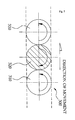
- the plurality of balls of the ball bearing 300 include steel balls 310 that make cloud motion by contacting directly the insertion grooves 153 and 253 of the base rails 151 and 152 and the slide rails 251 and 252, and resin balls 320 that have a smaller diameter than a diameter of the steel balls 310 and are formed of a synthetic resin material to have lubrication characteristics. As illustrated in FIG. 7 , the steel balls 310 and the resin balls 320 are alternately disposed. The resin balls 320 are rotated in an opposite direction to a rotation direction of the steel balls 310 and minimize friction resistance that may be generated between the steel balls 310, thereby preventing occurrence of noise and vibration and providing smooth cloud motion.
- the steel balls 310 contact directly the insertion grooves 153 and 253 and are loaded by the insertion grooves 153 and 253, and the resin balls 320 have a smaller diameter than the diameter of the steel balls 310 and thus are not loaded by the insertion grooves 153 and 253, thereby alleviating friction between the steel balls 310.
- the preload adjustment unit 600 is installed between one 251 of the slide rails 251 and 252 and the slide body 202 and adjusts an interval and an angle of the slide rail 251 with respect to the slide body 202. In this way, the preload adjustment unit 600 adjusts a preload applied to the ball bearing 300 that is disposed between the base rails 151 and 152 and the slide rails 251 and 252.
- the preload adjustment unit 600 includes conical wedges 620 and 621 and adjustment screws 640 and 641.
- a stepped assembly hole 213 is formed in a boundary surface between the rail combination groove 211 formed in a linear motion guide portion 210 of the slide body 202 and the slide rail 251 on which the rail combination groove 211 and the slide rail 251 face each other.
- the stepped assembly hole 213 passes through the boundary surface in a lengthwise direction of the preload adjustment unit 600.
- Guide support facets 212 each having an inclined surface with an inner diameter increasing from the stepped assembly hole 213 to both ends of the stepped assembly hole 213 in the lengthwise direction of the preload adjustment unit 600 are formed at both sides of the rail combination groove 221.
- Inclination guide facets 255 each having the same inclination angle as that of the guide support facets 212 are formed on the slide rail 251 that faces the guide support facets 212.
- Springs 610 and 611 are inserted in both ends of the stepped assembly hole 213, and the conical wedges 620 and 621 are inserted in outer portions of the springs 610 and 611.
- the conical wedges 620 and 621 are tapered and are disposed between the guide support facets 212 and the inclination guide facets 255 in the lengthwise direction of the preload adjustment unit 600.
- Support inserts 630 and 631 are inserted in outer portions of the conical wedges 620 and 621, and a fixing pin 635 that prevents rotation of the support inserts 630 and 631 is combined with the support inserts 630 and 631.
- the adjustment screws 640 and 641 are screw coupled to a screw hole 450 that is formed in the ball guide cover 400 and pass through the support inserts 630 and 631, thereby adjusting advancement/retreat movement of the conical wedge 620.
- the conical wedge 620 pressurizes the inclination guide facet 255 and moves forward towards the inclination guide facet 255 of the slide rail 251 and thus pushes the slide rail 215 to the outside.
- intervals between the base rails 151 and 152 and the slide rails 251 and 252 are decreased so that a preload applied to the steel balls 310 of the ball bearing 300 may be easily adjusted.
- angles of the slide rails 251 and 252 with respect to the base rails 151 and 152 may be adjusted.
- a preload amount indication gradation 645 is marked on a front side of the adjustment screw 640 to check and adjust the amount of preload by using screw rotation of the adjustment screw 640.
- the base rails 151 and 152 of the base member 100 and the slide rail 252 of the slide member 200 are securely combined with each other by performing a curling process when a metal adhesive is filled in each of the rail combination grooves 111 and 121 and 211 and 221 and the base rails 151 and 152 of the base member 100 and the slide rail 252 of the slide member 200 are adhered to each other.
- the slide rail 251 which is combined with the rail combination groove 211 of the slide member 200 and of which movement is adjusted by the preload adjustment unit 600 does not include an adhesion combination structure constituted by using a metal adhesive.
- the insertion grooves 153 and 253 that are formed in each of the base rails 151 and 152 and the slide rails 251 and 252, are configured in such a way that protruding friction support portions 154 and 254 are formed in the insertion grooves 153 and 253 and processed support facets 155 and 255 corresponding to curved surfaces of the steel balls 310 of the ball bearing 300 are formed on the protruding friction support portions 154 and 254 along the lengthwise direction of the preload adjustment unit 600 so that a friction force between the steel balls 310 may be minimized.
- a stopper unit 700 that limits a linear motion distance when the slide member 200 moves linearly may be disposed on both ends of the base member 100 in the lengthwise direction of the base member 100.
- the stopper unit 700 includes a support plate 710 that is bolt coupled on front and rear ends of a middle portion of the base member 100, and a shock absorber 720 and a stopper bolt 730 that are screw coupled to the support plate 710.
- the stopper unit 700 is stopped by a damper that is combined with a front end of the stopper bolt 730 when the slide member 200 is shock-absorbed by the shock absorber 720.
- the linear motion distance of the slide member 200 is limited according to forward and backward movement of the stopper bolt 730.
- an axial hole in which a ball screw is to be fixed may be formed in the support plate 710 and may be used to fix the ball screw.
- a coupling 800 is disposed in a central combination hole 250 of the slide member 200 so as to conveniently combine a linear motion actuator.
- the coupling 800 includes a base 810 that is combined with the central combination hole 250, a ball nut 820 that is rotatably combined with the base 810, and a clamping bolt 830 that is screw coupled to the ball nut 820 and then is screw coupled to the actuator.
- twist of the actuator may be corrected when the ball nut 820 is rotated around the base 810.
- Unexplained reference numeral B/T represents a bolt for engagement and assembling of individual elements
- unexplained reference numeral 460 represents a support cover that is screw coupled to the ball guide cover 400 and prevents escape of the balls of the ball bearing 300.
- the base body 101 excluding the base rails 151 and 152 and the slide body 201 excluding the slide rails 251 and 252 are formed of aluminum materials so that the light-weight of the adjustable preload type linear guide system may be maximized.
- linear motion of the adjustable preload type linear guide system illustrated in FIG. 1 is performed at high speed so that productivity of the adjustable preload type linear guide system may be improved.
- the track 420 of the ball guide cover 400 is inclined, as illustrated in FIG. 3 , so that a wide actuator accommodation space may be obtained.
- the size of the adjustable preload type linear guide system is reduced, and the adjustable preload type linear guide system is made slim so that a weight thereof may be reduced and production cost thereof may be reduced.
- the actuator since a variety of types of actuators are disposed in the actuator accommodation space between the slide member 200 and the base member 100, the actuator may be commonly used according to various usages and user's purposes. Since compatibility with other actuators is obtained, an exclusive linear guide system that is suitable for each equipment does not need to be designed and manufactured every time but a linear guide system is commonly designed and manufactured so that manufacturing cost of the linear guide system may be remarkably reduced.
- the ball bearing 300 includes a plurality of steel balls 310 and a plurality of resin balls 320 so that occurrence of noise and vibration may be reduced and smooth linear motion of the slide member 200 with respect to the base ember 100 may be performed.
- the plurality of steel balls 310 of the ball bearing 300 are supported by the processed support facets 155 and 255 that protrude from the insertion grooves 153 and 253 along a lengthwise direction of the preload adjustment unit 600 so that a friction force between the steel balls 310 of the ball bearing 300 may be minimized and slide motion of the slide member 200 may be more smoothly performed.
- the ball bearing 300 is worn out when it is being used, a preload of the ball bearing 300 is adjusted by the preload adjustment unit 600 so that the life span of the adjustable preload type linear guide system of FIG. 1 may be lengthened.
- an operation of replacing the steel balls 310 of the ball bearing 300 that is worn out during its usage like in a general linear guide system, does not need to be performed.
- Adjusting of the preload of the ball bearing 300 causes adjustment of a cloud motion force in which the slide member 200 is moved relative to the base member 100 so that linear motion of the slide member 200 may be precisely controlled.
Landscapes
- Engineering & Computer Science (AREA)
- General Engineering & Computer Science (AREA)
- Mechanical Engineering (AREA)
- Physics & Mathematics (AREA)
- Chemical & Material Sciences (AREA)
- Combustion & Propulsion (AREA)
- Electromagnetism (AREA)
- Power Engineering (AREA)
- Bearings For Parts Moving Linearly (AREA)
Abstract
Description
- The present invention relates to a linear guide system which is used for highly precise control of a linear position applicable in display devices, semiconductors, robots, machine tools, and the entire measurement and precision instruments industry, and more particularly, to an adjustable preload type linear guide system, wherein a base member and a slide member are slidably connected with each other for linear motion, and a linear motion actuator, such as a ball screw, a hydraulic cylinder, and a linear motor, is disposed between the base member and the slide member, thereby enabling the slide member to move linearly relative to the base member.
- Linear motion actuators are generally used for highly precise control of a linear position applicable in display devices, semiconductors, robots, machine tools, and the entire precision instruments industry, and a linear motion mechanism including a linear motion guide, for example, may be used as a linear guide unit that guides linear position control of the linear motion actuator.
- When linear motion mechanism systems are configured using the linear motion mechanism, as the weight of the linear motion guide and the weight of a support plate increase, cost for manufacturing the linear motion mechanism system increases, and the speed of the linear motion mechanism system is limited due to an increase in the size (volume) of the linear motion mechanism system.
- Such linear motion mechanism systems using the linear motion mechanism are designed and manufactured according to their applied fields and thus are not compatible with other systems, and manufacturing cost thereof increases.
- In addition, since the weight of the linear motion mechanism systems is heavy, there is a limitation in applying the linear motion mechanism systems to equipment, and their usage is restrictive.
- In these days, linear guide units are disclosed as linear motion mechanisms with better efficiency, the linear guide units including a base member having a function of a prop, a slide member that is slidably installed at the base member, and an actuator that moves the slide member relative to the base member.
- A guide portion for guiding slide motion is disposed on both the base member and the slide member, and a linear motion block is installed at the guide portion. The linear motion block includes a ball bearing including a plurality of steel balls that are moved on a caterpillar and embedded in the ball bearing so as to smoothly guide linear motion by minimizing friction that may occur when guiding slide motion.
- Such general linear guide units have the following problems.
- First, a preload applied to a ball bearing installed at the guide portion disposed on the base member and the slide member cannot be adjusted. That is, the steel balls of the ball bearing are combined with the ball bearing in such a way that the steel balls having the sizes selected according to levels of preloads when the steel balls are initially combined with the ball bearing are inserted in the ball bearing, and the preload of the ball bearing is varied as the ball bearing is worn out when it is being used, and thus the preload of the ball bearing cannot be adjusted. Since, in this way, the preload of the ball bearing cannot be adjusted when the ball bearing is being used, the degree of operation precision that may be lowered when the ball bearing is being used cannot be corrected. Thus, vibration and noise occur, and the life span of the linear guide units is reduced.
- Second, the base member and the slide member are formed of heavy metals with high rigidity and high abrasion resistance so as to ensure abrasion resistance so that the range of application of the linear guide units is limited.
- Third, steel balls having the same diameter are used in the ball bearing, as illustrated in
FIG. 14 . Friction between the steel balls occurs when the ball bearing is activated, resulting in accelerating abrasion and occurring noise and vibration. - The present invention provides an adjustable preload type linear guide system that may adjust a preload applied to a ball bearing so that abrasion of the ball bearing is reduced, occurrence of noise and vibration is prevented and highly precise linear motion is guided.
- The present invention also provides an adjustable preload type linear guide system, of which a life span is remarkably increased by preventing abrasion of a ball bearing.
- According to an aspect of the present invention, an adjustable preload type linear guide system includes: a base member having a base body, and a pair of base rails which are disposed in parallel to each other on the base body; a slide member having a slide body, and a pair of slide rails which are disposed on the slide body to face the pair of base rails, wherein the slide rails slide relative to the base rails by a ball bearing which is installed between the base rails and the slide rails, thereby enabling the slide member to slide relative to the base member; and a preload adjustment unit which is installed between one of the slide rails and the slide body for adjusting the intervals and angles of the slide rails with respect to the slide body, thereby adjusting the preload of the ball bearing which is disposed between the base rails and the slide rails.
- In an adjustable preload type linear guide system according to the present invention, a preload of a ball bearing may be adjusted when the ball bearing is being used so that unnecessary abrasion of the ball bearing may be prevented.
- In addition, occurrence of noise and vibration that may occur due to an improper preload of the ball bearing may be prevented so that the adjustable preload type linear guide system that guides linear motion with high precision may be provided.
- By preventing unnecessary abrasion of the ball bearing, the present invention provides an adjustable preload type linear guide system, of which a life span is remarkably lengthened.
-
-
FIG. 1 is a perspective view of an adjustable preload type linear guide system according to an embodiment of the present invention; -
FIG. 2 is an exploded perspective view of the adjustable preload type linear guide system illustrated inFIG. 1 ; -
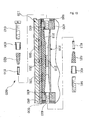
FIG. 3 is a side cross-sectional view of the adjustable preload type linear guide system illustrated inFIG. 1 ; -
FIG. 4 is an enlarged view of a portion ofFIG. 3 ; -
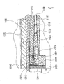
FIG. 5 is an enlarged view of another portion ofFIG. 3 ; -
FIG. 6 is an enlarged view of a portion ofFIG. 5 ; -
FIG. 7 illustrates a structure of a ball bearing illustrated inFIG. 7 ; -
FIG. 8 is an exploded perspective view of a preload adjustment unit illustrated inFIG. 1 ; -
FIG. 9 is a planer cross-sectional view of the adjustable preload type linear guide system illustrated inFIG. 1 ; -
FIG. 10 is a cross-sectional view of the preload adjustment unit illustrated inFIG. 8 ; -
FIGS. 11 and12 are enlarged views of portions ofFIG. 10 ; -
FIG. 13 is an enlarged view of a portion ofFIG. 2 ; and -
FIG. 14 illustrates a structure of a general ball bearing. - The present invention will now be described more fully with reference to the accompanying drawings, in which exemplary embodiments of the invention are shown.
FIG. 1 is a perspective view of an adjustable preload type linear guide system - According to an embodiment of the present invention, and
FIG. 2 is an exploded perspective view of the adjustable preload type linear guide system illustrated inFIG. 1 . - Referring to
FIGS. 1 and2 , the adjustable preload type linear guide system according to the current embodiment includes abase member 100, aslide member 200, and apreload adjustment unit 600. - Referring to
FIGS. 3 and4 , thebase member 100 includes abase body 101 and a pair ofbase rails base body 101. Thebase body 101 is formed of a light-weight aluminum profile that is formed by extrusion molding an aluminum material.Rail combination grooves base body 101 in a lengthwise direction of thebase body 101, and thebase rails rail combination grooves base rails - Referring to
FIGS. 5 and6 , after a metal adhesive is filled in therail combination grooves base body 101, thebase rails rail combination grooves - Referring to
FIGS. 3 and4 , theslide member 200 includes aslide body 201 and a pair ofslide rails slide body 201. Theslide body 201 is formed of a light-weight aluminum profile that is formed by extrusion molding an aluminum material.Rail combination grooves slide body 201 in a lengthwise direction of theslide body 201, and theslide rails rail combination grooves slide rails - Referring to
FIGS. 5 and6 , after a metal adhesive is filled in therail combination grooves slide body 201, theslide rails rail combination grooves - The
slide member 200 having the above structure is disposed between linearmotion guide portions base body 100. In this case, the pair ofbase rails base member 100 and the pair ofslide rails slide member 200 are disposed to face each other. In this case, a ball bearing 300 including a plurality of balls is disposed between thebase rails slide rails slide rails base rails - Referring to
FIG. 3 , an actuator accommodation space in which an actuator is to be disposed is formed in a middle portion of the adjustable preload type linear guide system in which thebase body 101 of thebase member 100 and theslide body 201 of theslide member 200 face each other. - Various types of devices, such as a linear motor, a ball screw, an air cylinder, a timing belt/pulley mechanism, and the like, may be used as the actuator. Since a proper actuator has only to be installed in the actuator accommodation space according to a usage purpose in this manner, the present invention has high compatibility.
- Referring to
FIGS. 2 through 4 , twotracks 410 are formed on theslide body 201 to pass through theslide body 201 in a lengthwise direction of theslide body 201.Insertion grooves base rails slide rails tracks 410 and constitute a caterpillar that is a path of the ball bearing 300 including a plurality of balls. - As illustrated in
FIG. 2 , ball guide covers 400 are respectively combined with both ends of theslide body 201 in the lengthwise direction of theslide body 201. Twotracks 420 are formed on each of the ball guide covers 400 to connect theinsertion grooves tracks 410, thereby preventing escape of theball bearing 300 and connecting caterpillar travel. Dust covers 500 are combined with outsides of the ball guide covers 400. - In this case, as illustrated in
FIG. 3 , a height of a central point of eachtrack 410 of theslide member 200 is different from a height of a central point of each of theinsertion grooves track 420 of theball guide cover 400 that connects theinsertion grooves track 410, is inclined with respect to a bottom surface of theball guide cover 400. When thetrack 420 of theball guide cover 400 is inclined with respect to the bottom surface of theball guide cover 400 in such a way that the height of each of theinsertion grooves track 410 of the slidingmember 200 are different from each other, a wide actuator accommodation space may be obtained, and a radius of gyration of thetrack 420 of theball guide cover 400 may be increased. That is, the radius of gyration of thetrack 420 of theball guide cover 400 may be increased so that cloud motion of the ball bearing may be smoothly performed, and the size of the adjustable preload type linear guide system may be reduced. - The plurality of balls of the
ball bearing 300 includesteel balls 310 that make cloud motion by contacting directly theinsertion grooves resin balls 320 that have a smaller diameter than a diameter of thesteel balls 310 and are formed of a synthetic resin material to have lubrication characteristics. As illustrated inFIG. 7 , thesteel balls 310 and theresin balls 320 are alternately disposed. Theresin balls 320 are rotated in an opposite direction to a rotation direction of thesteel balls 310 and minimize friction resistance that may be generated between thesteel balls 310, thereby preventing occurrence of noise and vibration and providing smooth cloud motion. That is, thesteel balls 310 contact directly theinsertion grooves insertion grooves resin balls 320 have a smaller diameter than the diameter of thesteel balls 310 and thus are not loaded by theinsertion grooves steel balls 310. - The
preload adjustment unit 600 is installed between one 251 of the slide rails 251 and 252 and the slide body 202 and adjusts an interval and an angle of theslide rail 251 with respect to the slide body 202. In this way, thepreload adjustment unit 600 adjusts a preload applied to theball bearing 300 that is disposed between the base rails 151 and 152 and the slide rails 251 and 252. - Referring to
FIGS. 8 through 12 , thepreload adjustment unit 600 includesconical wedges adjustment screws - A stepped
assembly hole 213 is formed in a boundary surface between the rail combination groove 211 formed in a linearmotion guide portion 210 of the slide body 202 and theslide rail 251 on which therail combination groove 211 and theslide rail 251 face each other. The steppedassembly hole 213 passes through the boundary surface in a lengthwise direction of thepreload adjustment unit 600.Guide support facets 212 each having an inclined surface with an inner diameter increasing from the steppedassembly hole 213 to both ends of the steppedassembly hole 213 in the lengthwise direction of thepreload adjustment unit 600 are formed at both sides of therail combination groove 221.Inclination guide facets 255 each having the same inclination angle as that of theguide support facets 212 are formed on theslide rail 251 that faces theguide support facets 212. -
Springs assembly hole 213, and theconical wedges springs conical wedges guide support facets 212 and theinclination guide facets 255 in the lengthwise direction of thepreload adjustment unit 600. Support inserts 630 and 631 are inserted in outer portions of theconical wedges pin 635 that prevents rotation of the support inserts 630 and 631 is combined with the support inserts 630 and 631. The adjustment screws 640 and 641 are screw coupled to ascrew hole 450 that is formed in theball guide cover 400 and pass through the support inserts 630 and 631, thereby adjusting advancement/retreat movement of theconical wedge 620. - When the
preload adjustment unit 600 allows theconical wedge 620 to move forward due to screw rotation of theadjustment screw 640, as illustrated inFIG. 12 , theconical wedge 620 pressurizes theinclination guide facet 255 and moves forward towards theinclination guide facet 255 of theslide rail 251 and thus pushes the slide rail 215 to the outside. - As a result, intervals between the base rails 151 and 152 and the slide rails 251 and 252 are decreased so that a preload applied to the
steel balls 310 of theball bearing 300 may be easily adjusted. In the same way, angles of the slide rails 251 and 252 with respect to the base rails 151 and 152 may be adjusted. - A preload
amount indication gradation 645 is marked on a front side of theadjustment screw 640 to check and adjust the amount of preload by using screw rotation of theadjustment screw 640. - The base rails 151 and 152 of the
base member 100 and theslide rail 252 of theslide member 200 are securely combined with each other by performing a curling process when a metal adhesive is filled in each of therail combination grooves base member 100 and theslide rail 252 of theslide member 200 are adhered to each other. - In this case, it is obvious that the
slide rail 251 which is combined with the rail combination groove 211 of theslide member 200 and of which movement is adjusted by thepreload adjustment unit 600 does not include an adhesion combination structure constituted by using a metal adhesive. - In addition, the
insertion grooves friction support portions insertion grooves support facets steel balls 310 of theball bearing 300 are formed on the protrudingfriction support portions preload adjustment unit 600 so that a friction force between thesteel balls 310 may be minimized. - In addition, a
stopper unit 700 that limits a linear motion distance when theslide member 200 moves linearly may be disposed on both ends of thebase member 100 in the lengthwise direction of thebase member 100. - The
stopper unit 700 includes asupport plate 710 that is bolt coupled on front and rear ends of a middle portion of thebase member 100, and ashock absorber 720 and astopper bolt 730 that are screw coupled to thesupport plate 710. - The
stopper unit 700 is stopped by a damper that is combined with a front end of thestopper bolt 730 when theslide member 200 is shock-absorbed by theshock absorber 720. The linear motion distance of theslide member 200 is limited according to forward and backward movement of thestopper bolt 730. - Referring to
FIG. 13 , an axial hole in which a ball screw is to be fixed may be formed in thesupport plate 710 and may be used to fix the ball screw. - Referring to
FIG. 3 , acoupling 800 is disposed in acentral combination hole 250 of theslide member 200 so as to conveniently combine a linear motion actuator. - The
coupling 800 includes a base 810 that is combined with thecentral combination hole 250, aball nut 820 that is rotatably combined with thebase 810, and aclamping bolt 830 that is screw coupled to theball nut 820 and then is screw coupled to the actuator. - Since the
ball nut 820 is combined with the base 810 to be rotated around thebase 810, even when a linear motion trajectory of the actuator and a linear motion trajectory of theslide member 200 do not coincide with each other slightly, twist of the actuator may be corrected when theball nut 820 is rotated around thebase 810. - Unexplained reference numeral B/T represents a bolt for engagement and assembling of individual elements, and
unexplained reference numeral 460 represents a support cover that is screw coupled to theball guide cover 400 and prevents escape of the balls of theball bearing 300. - Hereinafter, an operation of the adjustable preload type linear guide system having the above structure will be described.
- First, in the adjustable preload type linear guide system illustrated in
FIG. 1 , thebase body 101 excluding the base rails 151 and 152 and theslide body 201 excluding the slide rails 251 and 252 are formed of aluminum materials so that the light-weight of the adjustable preload type linear guide system may be maximized. Thus, linear motion of the adjustable preload type linear guide system illustrated inFIG. 1 is performed at high speed so that productivity of the adjustable preload type linear guide system may be improved. - In addition, the
track 420 of theball guide cover 400 is inclined, as illustrated inFIG. 3 , so that a wide actuator accommodation space may be obtained. As a result, the size of the adjustable preload type linear guide system is reduced, and the adjustable preload type linear guide system is made slim so that a weight thereof may be reduced and production cost thereof may be reduced. - In addition, since a variety of types of actuators are disposed in the actuator accommodation space between the
slide member 200 and thebase member 100, the actuator may be commonly used according to various usages and user's purposes. Since compatibility with other actuators is obtained, an exclusive linear guide system that is suitable for each equipment does not need to be designed and manufactured every time but a linear guide system is commonly designed and manufactured so that manufacturing cost of the linear guide system may be remarkably reduced. - In addition, the
ball bearing 300 includes a plurality ofsteel balls 310 and a plurality ofresin balls 320 so that occurrence of noise and vibration may be reduced and smooth linear motion of theslide member 200 with respect to thebase ember 100 may be performed. - Furthermore, the plurality of
steel balls 310 of theball bearing 300 are supported by the processedsupport facets insertion grooves preload adjustment unit 600 so that a friction force between thesteel balls 310 of theball bearing 300 may be minimized and slide motion of theslide member 200 may be more smoothly performed. - In the adjustable preload type linear guide system illustrated in
FIG. 1 , although theball bearing 300 is worn out when it is being used, a preload of theball bearing 300 is adjusted by thepreload adjustment unit 600 so that the life span of the adjustable preload type linear guide system ofFIG. 1 may be lengthened. Thus, an operation of replacing thesteel balls 310 of theball bearing 300 that is worn out during its usage, like in a general linear guide system, does not need to be performed. - Adjusting of the preload of the
ball bearing 300 causes adjustment of a cloud motion force in which theslide member 200 is moved relative to thebase member 100 so that linear motion of theslide member 200 may be precisely controlled.
Claims (9)
- An adjustable preload type linear guide system includes:a base member having a base body, and a pair of base rails which are disposed in parallel to each other on the base body;a slide member having a slide body, and a pair of slide rails which are disposed on the slide body to face the pair of base rails, wherein the slide rails slide relative to the base rails by a ball bearing which is installed between the base rails and the slide rails, thereby enabling the slide member to slide relative to the base member; anda preload adjustment unit which is installed between one of the slide rails and the slide body for adjusting the intervals and angles of the slide rails with respect to the slide body, thereby adjusting the preload of the ball bearing which is disposed between the base rails and the slide rails.
- The adjustable preload type linear guide system of claim 1, wherein the preload adjustment unit comprises conical wedges that are tapered and are disposed between the slide body and the slide rails in a lengthwise direction of the preload adjustment unit and adjustment screws that adjust advancement/retreat movement of the conical wedges in the lengthwise direction of the preload adjustment unit, and the preload adjustment unit adjusts intervals and angles of the slide rails with respect to the slide body based on the advancement/retreat movement of the conical wedges.
- The adjustable preload type linear guide system of claim 2, wherein two preload adjustment units are disposed on both ends of the slide body and the slide rails in the lengthwise direction of the preload adjustment units to face each other.
- The adjustable preload type linear guide system of claim 1, wherein the base body comprises an aluminum material and rail combination grooves formed in both sides of the base body, and the base rails comprise an abrasion resistance material with higher rigidity than aluminum and are inserted in the rail combination grooves of the base body and thus are combined with the rail combination grooves, and the slide body comprises an aluminum material and rail combination grooves formed in both sides of the slide body, and the slide rails comprise an abrasion resistance material with higher rigidity than aluminum and are inserted in the rail combination grooves of the slide body and thus are combined with the rail combination grooves
- The adjustable preload type linear guide system of claim 4, wherein the base rails are combined with the rail combination grooves after a metal adhesive is filled in the rail combination grooves of the base member.
- The adjustable preload type linear guide system of claim 1, wherein the ball bearing comprises a plurality of steel balls that contact directly the base rails and the slide rails and make cloud motion, and a plurality of resin balls that have a smaller diameter than a diameter of the steel balls and comprise a synthetic resin material to have lubrication characteristics.
- The adjustable preload type linear guide system of claim 6, wherein the plurality of steel balls and the plurality of resin balls are alternately disposed.
- The adjustable preload type linear guide system of claim 6, wherein insertion grooves in which the steel balls are disposed, are formed in each of the base rails and the slide rails, and protruding friction support portions are formed in the insertion grooves, and processed support facets corresponding to curved surfaces of the steel balls are formed on the protruding friction support portions.
- The adjustable preload type linear guide system of claim 1, further comprising a coupling that is installed on the slide member and allows an actuator for moving the slide member relative to the base member and the slide member to be easily combined with each other, wherein the coupling comprises a base that is combined with the slide member and a ball nut that is rotatably combined with the base.
Applications Claiming Priority (1)
| Application Number | Priority Date | Filing Date | Title |
|---|---|---|---|
| PCT/KR2009/002841 WO2010137755A1 (en) | 2009-05-28 | 2009-05-28 | Adjustable preload type linear guide system |
Publications (2)
| Publication Number | Publication Date |
|---|---|
| EP2436940A1 true EP2436940A1 (en) | 2012-04-04 |
| EP2436940A4 EP2436940A4 (en) | 2013-05-01 |
Family
ID=43222851
Family Applications (1)
| Application Number | Title | Priority Date | Filing Date |
|---|---|---|---|
| EP09845262.6A Withdrawn EP2436940A4 (en) | 2009-05-28 | 2009-05-28 | Adjustable preload type linear guide system |
Country Status (6)
| Country | Link |
|---|---|
| US (1) | US8313239B2 (en) |
| EP (1) | EP2436940A4 (en) |
| JP (1) | JP5712206B2 (en) |
| KR (1) | KR101198858B1 (en) |
| CN (1) | CN102449333B (en) |
| WO (1) | WO2010137755A1 (en) |
Cited By (5)
| Publication number | Priority date | Publication date | Assignee | Title |
|---|---|---|---|---|
| CN103447643A (en) * | 2013-08-22 | 2013-12-18 | 李冬庆 | Positioning and guide mechanism for carriage of spark erosion drilling machine |
| TWI500860B (en) * | 2012-11-02 | 2015-09-21 | ||
| WO2015173581A1 (en) * | 2014-05-14 | 2015-11-19 | Accuride International Limited | Re-circulating ball sliding support assembly |
| CN107855860A (en) * | 2017-11-11 | 2018-03-30 | 成都市龙泉星源机械厂 | A kind of steel-tube internal rag removal device |
| GB2560727A (en) * | 2017-03-22 | 2018-09-26 | Accuride Int Ltd | An adjustable bearing assembly |
Families Citing this family (41)
| Publication number | Priority date | Publication date | Assignee | Title |
|---|---|---|---|---|
| CN102080687A (en) * | 2010-12-27 | 2011-06-01 | 陈思雄 | Guide rail |
| JP5962977B2 (en) * | 2012-07-09 | 2016-08-03 | 株式会社ジェイテクト | Rack shaft support device and steering device using the same |
| CN102928220B (en) * | 2012-10-22 | 2014-11-26 | 清华大学 | Experimental device for comprehensively testing dynamic characteristics of linear feeding system |
| CN105308338B (en) * | 2013-06-28 | 2017-06-20 | 费斯托股份有限两合公司 | Linear actuator and the method for producing it |
| JP2016507710A (en) * | 2013-12-24 | 2016-03-10 | フェスト アーゲー ウント コー カーゲー | Linear drive and manufacturing method thereof |
| CN104801984B (en) * | 2014-01-24 | 2018-01-23 | 李宜君 | High-precision curvature adjusting and controlling mechanism of mechanical track seat |
| KR101583427B1 (en) * | 2014-08-21 | 2016-01-07 | 이동석 | Linear Guide |
| CN105537975B (en) * | 2014-10-28 | 2017-08-25 | 富鼎电子科技(嘉善)有限公司 | Sliding equipment and the processing unit (plant) using the sliding equipment |
| KR101633642B1 (en) * | 2014-12-11 | 2016-06-27 | 주식회사 지엔비 | Methode for Producting Linear Stage |
| DE102014119113B3 (en) * | 2014-12-18 | 2016-04-14 | Weiss Gmbh | Composite linear guide with fixing agent |
| TWI555925B (en) * | 2015-01-09 | 2016-11-01 | 國立勤益科技大學 | Adjustable pre-pressure self-lubricating block module |
| CN104568575B (en) * | 2015-01-12 | 2017-02-22 | 哈尔滨工程大学 | Force-applying push rod device and multi-axial load loading machine |
| JP6668652B2 (en) | 2015-09-18 | 2020-03-18 | 日本精工株式会社 | Linear motion guide device, end cap for linear motion guide device |
| JP6177294B2 (en) * | 2015-10-07 | 2017-08-09 | Thk株式会社 | Exercise guidance device |
| CN105697543A (en) * | 2016-02-29 | 2016-06-22 | 柳州正高科技有限公司 | Transverse moving device rack for engineering machinery |
| JP6864904B2 (en) * | 2016-12-27 | 2021-04-28 | 野村ユニソン株式会社 | 1-axis actuator |
| IT201700007671A1 (en) * | 2017-01-25 | 2018-07-25 | Comelz Spa | Tool handling structure in numerically controlled machines for processing rigid and semi-rigid flat materials. |
| KR101956462B1 (en) * | 2017-08-16 | 2019-06-24 | 에스케이에프코리아(주) | Linear module |
| TWI662202B (en) * | 2018-01-10 | 2019-06-11 | 高明鐵企業股份有限公司 | Linear guideway and rail thereof |
| KR102016423B1 (en) * | 2018-05-25 | 2019-09-02 | 주식회사 지엔비 | Linear stage with built-in Ready-made ball screw |
| WO2020021778A1 (en) * | 2018-07-27 | 2020-01-30 | 日本電気株式会社 | Information processing device, system, method, and computer-readable medium |
| KR101960638B1 (en) * | 2018-08-17 | 2019-03-20 | 박현희 | Lifting device for sliding-base |
| TWI669183B (en) * | 2018-09-27 | 2019-08-21 | 東佑達自動化科技股份有限公司 | Slide apparatus |
| US11545380B2 (en) * | 2018-11-01 | 2023-01-03 | Brooks Automation Us Llc | Transport apparatus with linear bearing |
| CN109707814A (en) * | 2019-01-25 | 2019-05-03 | 深圳市锐健电子有限公司 | A new type of ball screw device |
| KR102205079B1 (en) * | 2019-03-07 | 2021-01-20 | (주)코리아테크 | Clean Type Linear Guide Using Roller |
| CN111692205A (en) * | 2019-03-14 | 2020-09-22 | 河北蓝器科技有限公司 | Heavy-load composite guide rail |
| CN109752235B (en) * | 2019-03-27 | 2020-04-24 | 上海大学 | Giant electrorheological fluid extrusion force testing device |
| TWI692388B (en) * | 2019-05-10 | 2020-05-01 | 東佑達自動化科技股份有限公司 | Fixture device |
| TWI691655B (en) * | 2019-10-01 | 2020-04-21 | 東佑達自動化科技股份有限公司 | Lubrication duct and sliding table device with lubrication duct |
| CN111255805A (en) * | 2020-02-15 | 2020-06-09 | 东莞新行自动化科技有限公司 | Multi-directional stretched slide rail structure |
| KR200494333Y1 (en) * | 2020-02-26 | 2021-09-16 | 주식회사 피앤엠 | Linear Guide Table Cylinder |
| KR102244867B1 (en) * | 2020-12-11 | 2021-04-26 | 왕순옥 | Transfer device equipped with preload module for preventing clearance of top body and fixed guide rail |
| KR102681942B1 (en) | 2021-07-07 | 2024-07-08 | (주)원에스티 | A linear stage |
| CN114396425B (en) * | 2022-02-18 | 2023-02-03 | 中国商用飞机有限责任公司 | Roller device with adjustable support stiffness |
| DE102022120154B4 (en) * | 2022-08-10 | 2024-03-28 | Festo Se & Co. Kg | Linear guide device |
| DE102022129547A1 (en) | 2022-11-09 | 2024-05-16 | Festo Se & Co. Kg | Linear guide |
| DE102023121206B3 (en) * | 2023-08-09 | 2024-10-02 | Festo Se & Co. Kg | Linear guide |
| CN118705271B (en) * | 2024-07-24 | 2025-03-04 | 浙江精锐智能传动有限公司 | Linear guide slider |
| KR102824228B1 (en) * | 2024-09-05 | 2025-06-24 | 주식회사 오병 | Monocarrier device for transporting goods with an integrated structure |
| KR102862513B1 (en) * | 2024-11-08 | 2025-09-19 | 조성빈 | Turntable wrapping machine equipped with a robot arm that reduces vibration during horizontal movement and prevents sticking |
Family Cites Families (23)
| Publication number | Priority date | Publication date | Assignee | Title |
|---|---|---|---|---|
| JPS5535472Y2 (en) * | 1975-07-16 | 1980-08-21 | ||
| JPS5881215A (en) * | 1981-11-05 | 1983-05-16 | Nippon Thompson Co Ltd | Endless sliding bearing unit |
| JPH0650125B2 (en) * | 1986-12-23 | 1994-06-29 | 博 寺町 | Ball bearing for linear sliding |
| DE4005582C2 (en) | 1990-02-22 | 1996-01-25 | Neff Antriebstech Automation | Linear bearing and manufacturing process for its ball bypass devices |
| JP3188729B2 (en) * | 1991-06-05 | 2001-07-16 | 西部電機株式会社 | Precision slide mechanism |
| US5607238A (en) * | 1993-04-05 | 1997-03-04 | Deltron Precision, Inc. | Reduced friction linear slide with rolling elements |
| US5388913A (en) * | 1993-04-08 | 1995-02-14 | Ohmstede-Cawley, Ltd. | Linear bearing compensation system |
| IT230467Y1 (en) * | 1993-10-12 | 1999-06-07 | T M T Trasmissione Meccaniche | SHOE WITH ADJUSTABLE SLOPE POSITIONING |
| US5374128A (en) * | 1994-03-08 | 1994-12-20 | Automation Gages, Inc. | Linear ball slide |
| US5431498A (en) * | 1994-04-11 | 1995-07-11 | Thomson Industries, Inc. | Linear motion bearing |
| JP3412914B2 (en) * | 1994-05-20 | 2003-06-03 | Thk株式会社 | Rolling guide device and method of manufacturing moving block of rolling guide device |
| JP2965874B2 (en) * | 1994-10-20 | 1999-10-18 | 先生精機株式会社 | Actuator |
| JP3344131B2 (en) * | 1994-12-16 | 2002-11-11 | 日本精工株式会社 | Self-lubricating linear guide device |
| EP0769627B1 (en) * | 1995-10-17 | 2000-08-02 | Deutsche Star GmbH | Linear guiding device |
| DE19601407B4 (en) * | 1996-01-17 | 2006-09-28 | Skf Linearsysteme Gmbh | Two-lane guidance system |
| US5868499A (en) * | 1996-09-06 | 1999-02-09 | Deutsche Star Gmbh | Linear guiding unit |
| KR100380194B1 (en) * | 2000-09-09 | 2003-04-23 | (주) 티피씨 메카트로닉스 | Horizontal cylinder |
| JP2002303320A (en) * | 2001-04-06 | 2002-10-18 | Smc Corp | Manufacturing method of frame with guide |
| JP2004204901A (en) * | 2002-12-24 | 2004-07-22 | Nikken Kosakusho Works Ltd | Linear motion guiding device |
| JP4531053B2 (en) * | 2004-09-08 | 2010-08-25 | Thk株式会社 | Linear guide device and method of manufacturing track rail thereof |
| KR100706843B1 (en) * | 2006-05-22 | 2007-04-13 | 주식회사 미드 | Cross bearing units |
| JP2008232267A (en) * | 2007-03-20 | 2008-10-02 | Thk Co Ltd | Rolling guide device |
| KR100901162B1 (en) | 2008-01-31 | 2009-06-04 | (주)팜코 | Preload adjustable profile linear guide system |
-
2009
- 2009-05-28 KR KR1020107016178A patent/KR101198858B1/en active Active
- 2009-05-28 JP JP2012512935A patent/JP5712206B2/en active Active
- 2009-05-28 WO PCT/KR2009/002841 patent/WO2010137755A1/en not_active Ceased
- 2009-05-28 EP EP09845262.6A patent/EP2436940A4/en not_active Withdrawn
- 2009-05-28 CN CN200980160079.1A patent/CN102449333B/en active Active
-
2011
- 2011-11-22 US US13/302,126 patent/US8313239B2/en active Active
Cited By (7)
| Publication number | Priority date | Publication date | Assignee | Title |
|---|---|---|---|---|
| TWI500860B (en) * | 2012-11-02 | 2015-09-21 | ||
| CN103447643A (en) * | 2013-08-22 | 2013-12-18 | 李冬庆 | Positioning and guide mechanism for carriage of spark erosion drilling machine |
| WO2015173581A1 (en) * | 2014-05-14 | 2015-11-19 | Accuride International Limited | Re-circulating ball sliding support assembly |
| US10066667B2 (en) | 2014-05-14 | 2018-09-04 | Accuride International Limited | Re-circulating ball sliding support assembly |
| GB2560727A (en) * | 2017-03-22 | 2018-09-26 | Accuride Int Ltd | An adjustable bearing assembly |
| GB2560727B (en) * | 2017-03-22 | 2020-06-17 | Accuride Int Ltd | An adjustable bearing assembly |
| CN107855860A (en) * | 2017-11-11 | 2018-03-30 | 成都市龙泉星源机械厂 | A kind of steel-tube internal rag removal device |
Also Published As
| Publication number | Publication date |
|---|---|
| WO2010137755A1 (en) | 2010-12-02 |
| CN102449333B (en) | 2015-04-01 |
| US20120128277A1 (en) | 2012-05-24 |
| JP2012528284A (en) | 2012-11-12 |
| CN102449333A (en) | 2012-05-09 |
| KR101198858B1 (en) | 2012-11-07 |
| KR20100133357A (en) | 2010-12-21 |
| JP5712206B2 (en) | 2015-05-07 |
| EP2436940A4 (en) | 2013-05-01 |
| US8313239B2 (en) | 2012-11-20 |
Similar Documents
| Publication | Publication Date | Title |
|---|---|---|
| US8313239B2 (en) | Adjustable preload type linear guide system | |
| KR100901162B1 (en) | Preload adjustable profile linear guide system | |
| US6476525B2 (en) | Linear actuator | |
| US7029214B2 (en) | Linear guide apparatus | |
| US5217308A (en) | Linear motion roller contact bearing assembly with bearing race inserts | |
| US8757017B2 (en) | Linear movement device with omega drive | |
| CN104350295B (en) | Guide body and the motion guide device for possessing it | |
| US11105366B2 (en) | Long span lead screw assembly with anti-backlash nut and wear compensated load bearing element | |
| EP3143298B1 (en) | Re-circulating ball sliding support assembly | |
| US10415640B2 (en) | Motion guide device and actuator | |
| US20100139426A1 (en) | Actuator | |
| US5678663A (en) | Braking apparatus and rolling guide unit on which it is equipped | |
| JP2017009080A (en) | Rail slider unit | |
| US10876575B2 (en) | Motion guide device | |
| JP2002327741A (en) | Linear motion bearing structure | |
| TW202331118A (en) | Slide bearing guide device, in particular linear guide device, with pre-loaded sliding element and carriage therefor | |
| US8100025B2 (en) | Rolling element retainer | |
| CN101981334A (en) | Surround guide for rolling elements and linear guide units equipped with it | |
| US6109789A (en) | Linear slide | |
| EP2933511A2 (en) | Machine guideways | |
| EP1403541A1 (en) | Linear rolling element bearing with rollers retained in a flexible cage | |
| US20060140517A1 (en) | Linear guiding unit | |
| KR100679680B1 (en) | Linear guide | |
| US8684605B2 (en) | Guide rail | |
| TWI555925B (en) | Adjustable pre-pressure self-lubricating block module |
Legal Events
| Date | Code | Title | Description |
|---|---|---|---|
| PUAI | Public reference made under article 153(3) epc to a published international application that has entered the european phase |
Free format text: ORIGINAL CODE: 0009012 |
|
| 17P | Request for examination filed |
Effective date: 20111223 |
|
| AK | Designated contracting states |
Kind code of ref document: A1 Designated state(s): AT BE BG CH CY CZ DE DK EE ES FI FR GB GR HR HU IE IS IT LI LT LU LV MC MK MT NL NO PL PT RO SE SI SK TR |
|
| DAX | Request for extension of the european patent (deleted) | ||
| A4 | Supplementary search report drawn up and despatched |
Effective date: 20130403 |
|
| RIC1 | Information provided on ipc code assigned before grant |
Ipc: F16C 29/04 20060101AFI20130326BHEP Ipc: F16C 29/12 20060101ALI20130326BHEP Ipc: H02K 41/02 20060101ALI20130326BHEP Ipc: B23Q 1/26 20060101ALN20130326BHEP Ipc: B23Q 1/25 20060101ALI20130326BHEP Ipc: B23Q 1/30 20060101ALN20130326BHEP Ipc: F16C 33/32 20060101ALI20130326BHEP Ipc: F16C 29/06 20060101ALI20130326BHEP Ipc: F16C 33/37 20060101ALI20130326BHEP Ipc: F16C 29/00 20060101ALI20130326BHEP |
|
| RAP1 | Party data changed (applicant data changed or rights of an application transferred) |
Owner name: KOREAROBOTECH CO., LTD. |
|
| STAA | Information on the status of an ep patent application or granted ep patent |
Free format text: STATUS: THE APPLICATION IS DEEMED TO BE WITHDRAWN |
|
| 18D | Application deemed to be withdrawn |
Effective date: 20141202 |