EP2436903A2 - Pulse detonation tube with local flexural wave modifying feature - Google Patents
Pulse detonation tube with local flexural wave modifying feature Download PDFInfo
- Publication number
- EP2436903A2 EP2436903A2 EP11183082A EP11183082A EP2436903A2 EP 2436903 A2 EP2436903 A2 EP 2436903A2 EP 11183082 A EP11183082 A EP 11183082A EP 11183082 A EP11183082 A EP 11183082A EP 2436903 A2 EP2436903 A2 EP 2436903A2
- Authority
- EP
- European Patent Office
- Prior art keywords
- tube
- pulse detonation
- flexural wave
- detonation tube
- pulse
- Prior art date
- Legal status (The legal status is an assumption and is not a legal conclusion. Google has not performed a legal analysis and makes no representation as to the accuracy of the status listed.)
- Withdrawn
Links
- 238000005474 detonation Methods 0.000 title claims abstract description 247
- 230000008878 coupling Effects 0.000 claims description 44
- 238000010168 coupling process Methods 0.000 claims description 44
- 238000005859 coupling reaction Methods 0.000 claims description 44
- 239000000446 fuel Substances 0.000 claims description 15
- 230000007423 decrease Effects 0.000 claims description 10
- 238000011144 upstream manufacturing Methods 0.000 claims description 8
- 230000003321 amplification Effects 0.000 description 31
- 238000003199 nucleic acid amplification method Methods 0.000 description 31
- 239000000463 material Substances 0.000 description 11
- 238000010586 diagram Methods 0.000 description 10
- 238000002485 combustion reaction Methods 0.000 description 8
- 230000001965 increasing effect Effects 0.000 description 8
- 230000003068 static effect Effects 0.000 description 7
- 238000001816 cooling Methods 0.000 description 6
- 239000007789 gas Substances 0.000 description 6
- 239000000203 mixture Substances 0.000 description 6
- 230000001902 propagating effect Effects 0.000 description 5
- 230000029058 respiratory gaseous exchange Effects 0.000 description 5
- 230000000996 additive effect Effects 0.000 description 4
- 238000004200 deflagration Methods 0.000 description 4
- 230000006870 function Effects 0.000 description 4
- 238000000034 method Methods 0.000 description 4
- 230000002452 interceptive effect Effects 0.000 description 3
- 238000004519 manufacturing process Methods 0.000 description 3
- 230000008569 process Effects 0.000 description 3
- GQPLMRYTRLFLPF-UHFFFAOYSA-N Nitrous Oxide Chemical compound [O-][N+]#N GQPLMRYTRLFLPF-UHFFFAOYSA-N 0.000 description 2
- 230000008901 benefit Effects 0.000 description 2
- 230000003247 decreasing effect Effects 0.000 description 2
- 230000001419 dependent effect Effects 0.000 description 2
- 238000013461 design Methods 0.000 description 2
- 238000005516 engineering process Methods 0.000 description 2
- 230000002708 enhancing effect Effects 0.000 description 2
- 230000035939 shock Effects 0.000 description 2
- 230000007704 transition Effects 0.000 description 2
- QVGXLLKOCUKJST-UHFFFAOYSA-N atomic oxygen Chemical compound [O] QVGXLLKOCUKJST-UHFFFAOYSA-N 0.000 description 1
- 238000006243 chemical reaction Methods 0.000 description 1
- 230000008602 contraction Effects 0.000 description 1
- 238000013016 damping Methods 0.000 description 1
- 230000017525 heat dissipation Effects 0.000 description 1
- 230000001939 inductive effect Effects 0.000 description 1
- 230000003993 interaction Effects 0.000 description 1
- 239000001272 nitrous oxide Substances 0.000 description 1
- 239000007800 oxidant agent Substances 0.000 description 1
- 229910052760 oxygen Inorganic materials 0.000 description 1
- 239000001301 oxygen Substances 0.000 description 1
- 238000010248 power generation Methods 0.000 description 1
- VEMKTZHHVJILDY-UHFFFAOYSA-N resmethrin Chemical compound CC1(C)C(C=C(C)C)C1C(=O)OCC1=COC(CC=2C=CC=CC=2)=C1 VEMKTZHHVJILDY-UHFFFAOYSA-N 0.000 description 1
- 239000007787 solid Substances 0.000 description 1
Images


Classifications
-
- F—MECHANICAL ENGINEERING; LIGHTING; HEATING; WEAPONS; BLASTING
- F02—COMBUSTION ENGINES; HOT-GAS OR COMBUSTION-PRODUCT ENGINE PLANTS
- F02K—JET-PROPULSION PLANTS
- F02K7/00—Plants in which the working fluid is used in a jet only, i.e. the plants not having a turbine or other engine driving a compressor or a ducted fan; Control thereof
- F02K7/02—Plants in which the working fluid is used in a jet only, i.e. the plants not having a turbine or other engine driving a compressor or a ducted fan; Control thereof the jet being intermittent, i.e. pulse-jet
-
- Y—GENERAL TAGGING OF NEW TECHNOLOGICAL DEVELOPMENTS; GENERAL TAGGING OF CROSS-SECTIONAL TECHNOLOGIES SPANNING OVER SEVERAL SECTIONS OF THE IPC; TECHNICAL SUBJECTS COVERED BY FORMER USPC CROSS-REFERENCE ART COLLECTIONS [XRACs] AND DIGESTS
- Y02—TECHNOLOGIES OR APPLICATIONS FOR MITIGATION OR ADAPTATION AGAINST CLIMATE CHANGE
- Y02T—CLIMATE CHANGE MITIGATION TECHNOLOGIES RELATED TO TRANSPORTATION
- Y02T50/00—Aeronautics or air transport
- Y02T50/60—Efficient propulsion technologies, e.g. for aircraft
Definitions
- the subject matter disclosed herein relates generally to a pulse detonation tube and, more specifically, to enhancing the durability of the pulse detonation tube by employing a local flexural wave modifying feature.
- Pulse detonation combustion can be utilized in various practical engine applications.
- An example of such an application is the development of a pulse detonation engine (PDE) where hot detonation products are directed through an exit nozzle to generate thrust for aerospace propulsion.
- Pulse detonation engines that include multiple combustor chambers are sometimes referred to as a "multi-tube" configuration for a pulse detonation engine.
- Another example is the development of a "hybrid” engine that uses both conventional gas turbine engine technology and pulse detonation (PD) technology to enhance operational efficiency.
- PDTE pulse detonation turbine engines
- PDTE pulse detonation turbine engines
- the combustion reaction is a detonation wave that moves at supersonic speed, thereby increasing the efficiency of the combustion process as compared to subsonic deflagration combustion.
- air and fuel are typically injected into the pulse detonation tube in discrete pulses.
- the fuel-air mixture is then detonated by an ignition source, thereby establishing a detonation wave that propagates downstream through the tube at a supersonic velocity.
- a weaker shock wave may propagate upstream toward the combustor inlet.
- the detonation process produces pressurized exhaust gas within the pulse detonation tube that may be used to produce thrust or be converted to work in a turbine.
- material properties and geometry of the pulse detonation tube at least partially define a speed at which mechanical waves travel through the structure of the tube.
- This speed may be known as the flexural wave speed and may include a breathing mode component and a dilatation component.
- the sharp pressure rise associated with the detonation wave front generates a mechanical wave at each discrete location along the length of the tube. These mechanical waves propagate through the tube structure at the flexural wave speed. If the speed of the detonation wave is substantially similar to the flexural wave speed of the tube, the detonation wave will excite the pulse detonation tube at resonance.
- the strain resulting from the detonation wave will be significantly greater than the strain associated with static pressure loading at the detonation wave pressure.
- Such strain amplification may increase along the length of the tube due to the additive effect of multiple coalescing flexural waves.
- the strain may be amplified by a factor of 2, 3, 4, 5, 6, or more compared to static pressure loading. As a result, the longevity of the pulse detonation tube may be significantly reduced.
- a pulse detonation tube in one embodiment, includes a continuous base tube having a substantially uniform wall thickness.
- the pulse detonation tube also includes a local flexural wave modifying feature configured to locally vary a flexural wave speed such that the flexural wave speed through the pulse detonation tube is different than an expected detonation wave speed, and/or to locally dissipate flexural wave energy.
- a pulse detonation tube in another embodiment, includes a continuous base tube having a substantially uniform wall thickness.
- the pulse detonation tube also includes an air valve disposed at an upstream end of the pulse detonation tube and configured to emanate an air pulse in a downstream direction.
- the pulse detonation tube further includes a fuel injector configured to inject fuel into each air pulse to establish a mixed fuel-air region, and an ignition source disposed downstream from the air valve and configured to initiate a detonation wave by igniting the mixed fuel-air region.
- the pulse detonation tube includes a local flexural wave modifying feature positioned downstream from the ignition source.
- the local flexural wave modifying feature is configured to locally vary a flexural wave speed such that the flexural wave speed through the pulse detonation tube is different than an expected speed of the detonation wave, and/or to locally dissipate flexural wave energy.
- a pulse detonation tube in a further embodiment, includes a continuous base tube having a substantially uniform wall thickness.
- the continuous base tube is configured to facilitate propagation of a detonation wave through a downstream region of the continuous base tube.
- the pulse detonation tube also includes a local flexural wave modifying feature proximate to the downstream region.
- the local flexural wave modifying feature is configured to locally vary a flexural wave speed such that the flexural wave speed through the pulse detonation tube is different than an expected speed of the detonation wave, and/or to locally dissipate flexural wave energy.
- a pulse detonation tube is understood to mean any device or system that produces both a pressure rise and velocity increase from a series of repeated detonations or quasi-detonations within the tube.
- a "quasi-detonation” is a supersonic turbulent combustion process that produces a pressure rise and velocity increase higher than the pressure rise and velocity increase produced by a deflagration wave.
- Embodiments of pulse detonation tubes include a means of igniting a fuel/oxidizer mixture, for example a fuel/air mixture, and a detonation chamber, in which pressure wave fronts initiated by the ignition process coalesce to produce a detonation wave or quasi-detonation.
- detonation or quasi-detonation is initiated either by external ignition, such as spark discharge or laser pulse, or by gas dynamic processes, such as shock focusing, auto ignition or by another detonation (i.e. crossfire).
- detonation is used to mean either a detonation or quasi-detonation.
- a pulse detonation tube may substantially reduce strain within a pulse detonation tube by locally varying flexural wave propagation through the tube such that a detonation wave does not excite the tube at a resonance frequency (e.g., the breathing mode resonance frequency).
- a pulse detonation tube includes a continuous base tube having a substantially uniform wall thickness.
- the continuous base tube is configured to facilitate propagation of a detonation wave through a downstream region of the continuous base tube.
- the pulse detonation tube also includes a local flexural wave modifying feature coupled to the continuous base tube proximate to the downstream region.
- the local flexural wave modifying feature is configured to locally vary a flexural wave speed of the pulse detonation tube such that the flexural wave speed is different than an expected speed of the detonation wave and/or to locally dissipate flexural wave energy. In this manner, interaction between the detonation wave and the flexural waves will not drive the pulse detonation tube at a resonance frequency, thereby substantially reducing strain within the tube. As a result, the longevity of the pulse detonation tube may be significantly enhanced, and/or the pulse detonation tube may be constructed from lighter and/or less expensive materials.
- FIG. 1 is a schematic diagram of an embodiment of a pulse detonation tube 10 that may be used to produce thrust and/or drive a turbine.
- the pulse detonation tube 10 includes a continuous base tube 12 having a substantially uniform wall thickness.
- the pulse detonation tube 10 also includes at least one fuel injector 14 (e.g., 1, 2, 3, 4, 5, 6, 7, 8, 9, 10, or more), which feeds fuel to a combustion zone located within the pulse detonation tube 10.
- the pulse detonation tube 10 includes an air valve 16 disposed to an upstream region 18 of the tube 10. The air valve 16 is configured to inject discrete air pulses into the pulse detonation tube 10.
- the fuel injector 14 is configured to inj ect fuel into each of the air pulses to establish a fuel-air mixture suitable for detonation.
- An ignition source 20 then detonates the fuel-air mixture, thereby forming a detonation wave 22 that propagates through the pulse detonation tube 10 in a downstream direction 24.
- the detonation wave 22 passes through a downstream region 26 of the tube 10, e.g., a region downstream from the ignition source 20.
- Exhaust gas 28 from the detonation reaction exits the pulse detonation tube 10 in the downstream direction 24 and may be utilized to produce thrust or to drive a turbine, for example.
- the pulse detonation tube 10 includes a local flexural wave modifying feature coupled to the continuous base tube 12 proximate to the downstream region 26.
- the local flexural wave modifying feature is configured to locally vary a flexural wave speed of the pulse detonation tube 10 such that the flexural wave speed is different than an expected speed of the detonation wave 22 and/or to locally dissipate flexural wave energy.
- material properties and geometry of the pulse detonation tube 10 at least partially define a speed at which mechanical waves travel through the structure of the tube 10. This speed may be known as the flexural wave speed and may include a breathing mode component and a dilatation component.
- the sharp pressure rise associated with the detonation wave front generates a mechanical wave at each discrete location along the length of the tube 10.
- These mechanical waves propagate through the tube structure at the flexural wave speed. If the speed of the detonation wave 22 is substantially similar to the flexural wave speed of the tube, the detonation wave 22 will excite the pulse detonation tube 10 at resonance. Consequently, the strain resulting from the detonation wave 22 will be significantly greater than the strain associated with static pressure loading at the detonation wave pressure. Such strain amplification may increase along the length of the tube 10 due to the additive effect of multiple coalescing flexural waves.
- the strain may be amplified by a factor of 2, 3, 4, 5, 6, or more compared to static pressure loading.
- the local flexural wave modifying feature is configured to locally vary a flexural wave speed of the pulse detonation tube 10 such that the flexural wave speed is different than the speed of the detonation wave 22 and/or to locally dissipate flexural wave energy, the detonation wave 22 will not drive the pulse detonation tube at a resonance frequency (e.g., the breathing mode resonance frequency), thereby substantially reducing strain within the tube structure.
- the longevity of the pulse detonation tube 10 may be significantly enhanced, and/or the pulse detonation tube may be constructed from lighter and/or less expensive materials.
- the pulse detonation tube 10 may be employed within a pulse detonation combustor of a gas turbine engine.
- the exhaust gas from the pulse detonation tube 10 may be utilized to drive a turbine to rotate.
- the pulse detonation tube 10 may be employed within a "pure" pulse detonation engine in which the exhaust is directed through a converging-diverging nozzle directly to ambient to produce raw thrust.
- oxidizers e.g., oxygen, nitrous oxide, etc.
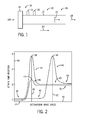
- FIG. 2 is an exemplary graph of strain amplification versus detonation wave speed for a pulse detonation tube having a substantially uniform wall thickness and for a pulse detonation tube having a local flexural wave modifying feature.
- a horizontal axis 30 represents detonation wave speed
- a vertical axis 32 represents strain amplification
- a curve 34 represents strain amplification as a function of detonation wave speed at a discrete location along a pulse detonation tube having a substantially uniform wall thickness, such as the continuous base tube 12.
- Strain amplification may be defined as the ratio of strain induced by the detonation wave 22 to the expected strain associated with static pressure loading at the detonation wave pressure.
- the strain amplification curve 34 includes a subcritical region 36, a critical region 38 and a supercritical region 40.
- the strain amplification curve 34 reaches a maximum at the critical region 38 where the detonation wave speed is substantially equal to the flexural wave speed of the pulse detonation tube 10. This speed may be known as the critical wave speed 42.
- operating the pulse detonation tube 10 at the critical wave speed 42 may result in a strain amplification of approximately 4.
- the maximum strain amplification may be higher or lower in alternative tube configurations.
- the maximum strain amplification may be greater than approximately 2, 3, 4, 5, 6, or more.
- strain amplification decreases rapidly as detonation wave speed decreases below the critical wave speed 42. Consequently, the strain amplification within the subcritical region 36 may be approximately 1. However, it should be appreciated that the strain amplification within the subcritical region may be approximately, 1.2, 1.4. 1.6, 1.8, or more in alternative embodiments. Similarly, as the detonation wave speed increases above the critical wave speed 42, the strain amplification decreases to approximately 2, and remains substantially constant throughout the supercritical region 40. While the strain amplification is approximately 2 in the supercritical region 40 of the present embodiment, it should be appreciated that alternative tube configurations may produce a higher or lower amplification factor within the supercritical region 40. In addition, it should be appreciated that the strain amplification may begin to decrease toward zero as detonation wave speed increases beyond the supercritical region 40.
- the graph also includes a curve 44 which represents strain amplification as a function of detonation wave speed at a discrete location along a pulse detonation tube 10 having a local flexural wave modifying feature. Similar to the curve 34, the curve 44 includes a subcritical region 46, a critical region 48 and a supercritical region 50. However, as indicated by the position of the critical region 48, the critical wave speed 52 of the pulse detonation tube having the local flexural wave modifying feature is significantly greater than the critical wave speed 42 of the tube having a substantially uniform wall thickness. In other words, mechanical waves may travel through the structure of the tube having the local flexural wave modifying feature faster than the tube having a substantially uniform wall thickness.
- the strain amplification within the tube having a substantially uniform wall thickness will be approximately 4.
- the critical wave speed 42 falls within the subcritical region 46 of the tube having the local flexural wave modifying feature
- the strain amplification will be approximately 1. Consequently, the longevity of the pulse detonation tube having the local flexural wave modifying feature may be significantly greater than the longevity of the tube having a substantially uniform wall thickness.
- the graph includes another curve 45 which represents strain amplification as a function of detonation wave speed at a discrete location along a pulse detonation tube 10 having an alternative local flexural wave modifying feature.
- the curve 45 includes a subcritical region 47, a critical region 49 and a supercritical region 51 which substantially correspond to the detonation wave speeds associated with the respective regions of the curve 34.
- the strain amplification associated with the critical region 49 of the curve 45 is substantially lower than the strain amplification associated with the critical region 38 of the curve 34.
- the pulse detonation tube associated with the curve 45 includes a local flexural wave modifying feature configured to locally dissipate flexural wave energy, thereby reducing the maximum strain amplification to approximately 2.25.
- the local flexural wave modifying feature may interfere with the flexural waves propagating through the tube in the downstream direction, thereby substantially reducing or eliminating the possibility of establishing resonant coupling between the detonation wave and the tube. Consequently, even though the critical wave speed 42 of the curve 45 remains substantially similar to the critical wave speed of the curve 34, the strain amplification is substantially reduced, thereby resulting in extended longevity of the pulse detonation tube. While the maximum strain amplification of the curve 45 is approximately 2.25, it should be appreciated that alternative local flexural wave modifying features may produce higher or lower maximum strain amplifications.
- the graph represents strain amplification as a function of detonation wave speed at one discrete location along the length of the pulse detonation tube 10.
- strain amplification may increase along the length of the tube due to the additive effect of multiple coalescing flexural waves. Consequently, the strain within the downstream region 26 of the pulse detonation tube 10 may be significantly greater than the strain within the upstream region 18.
- the local flexural wave modifying feature may be coupled to the tube 10 proximate to the downstream region 26, thereby reducing strain and enabling the pulse detonation tube to be constructed from lighter and/or less expensive materials.
- the flexural wave speed of a pulse detonation tube 10 may be at least partially dependent on the dimensions and/or material properties of the tube.
- varying the diameter of the tube 10 may affect the flow properties (e.g., pressure, velocity, temperature, etc.) of the detonation wave 22. Consequently, it may be desirable to locally vary the thickness of the tube walls to adjust the flexural wave speed of the pulse detonation tube 10.
- FIG. 3 is a schematic diagram of an embodiment of a pulse detonation tube 10 having an outer tube 54 coupled to the continuous base tube 12.
- the flexural wave speed is at least partially dependent on the tube wall thickness. Specifically, increasing the thickness of the tube walls increases the speed at which flexural waves travel through the pulse detonation tube 10.
- the continuous base tube 12 has a substantially uniform wall thickness 56, thereby establishing a particular flexural wave speed. If the speed of the detonation wave 22 is substantially similar to the flexural wave speed, a resonance will be established within the pulse detonation tube 10 that significantly increases strain compared to static pressure loading at the detonation wave pressure.
- the flexural wave speed will be increased such that the detonation wave 22 will not drive the tube 10 at a resonance frequency (e.g., the breathing mode resonance frequency), thereby substantially reducing strain within the pulse detonation tube 10.
- a resonance frequency e.g., the breathing mode resonance frequency
- the detonation wave 22 may propagate through the pulse detonation tube at approximately 1700 m/s. If the flexural wave speed of the continuous base tube 12 is also approximately 1700 m/s, the detonation wave 22 will induce a resonance within the pulse detonation tube 10 that significantly increases strain compared to static pressure loading at the detonation wave pressure. Moreover, due to the additive effect of multiple coalescing flexural waves, strain may increase along the length of the tube 10. Consequently, by coupling an outer tube 54 to the continuous base tube 12 proximate to the downstream region 26, the thickness 58 of the pulse detonation tube 10 will be increased, thereby increasing flexural wave speed above the detonation wave speed. For example, the flexural wave speed may be increased to approximately 2000 m/s. As a result, the downstream portion 26 of the tube 10 will be in the subcritical region, thereby resulting in decreased strain and increased tube longevity.
- an outer tube 54 is coupled to the continuous base tube 12 in the present embodiment, it should be appreciated that alternative embodiments may employ a tube 12 having a wall thickness that increases along the downstream direction 24. Furthermore, it should be appreciated that wall thickness may be decreased within the downstream region 26, thereby enabling the pulse detonation tube 10 to operate within the supercritical region. While the strain within the supercritical region may be greater than the strain within the subcritical region, the strain is less than the strain within the critical region. In addition, the thinner tube walls may significantly decrease the weight and/or manufacturing costs of the pulse detonation tube 10.
- FIG. 4 is a schematic diagram of an embodiment of a pulse detonation tube 10 having a wall thickness that periodically increases and decreases along a downstream direction 24.
- the pulse detonation tube 10 includes a wavy or undulating surfacing having crests 60 and troughs 62.
- the flexural wave speed of the pulse detonation tube 10 will periodically increase and decrease based on the local tube wall thickness. Because the flexural wave speed varies throughout the downstream region 26 of the tube 10, the possibility of establishing resonant coupling between the detonation wave 22 and the tube 10 will be significantly reduced or eliminated. Consequently, strain within the tube 10 will be significantly lower than a tube having a substantially uniform wall thickness.
- While the present embodiment includes two crests 60 and one trough 62, it should be appreciated that alternative embodiments may include more or fewer crests 60 and/or troughs 62. In addition, it should be appreciated that the amplitude and/or frequency of the wavy surface may vary in alternative embodiments.
- FIG. 5 is a schematic diagram of an embodiment of a pulse detonation tube 10 having multiple rings 64 disposed about the continuous base tube 12 and coupled to an exterior surface 66 of the base tube 12 proximate to the downstream region 26.
- the rings 64 are configured to locally dissipate flexural wave energy. Specifically, the rings 64 will interfere with the flexural waves propagating through the tube 10 in the downstream direction 24, thereby substantially reducing or eliminating the possibility of establishing resonant coupling between the detonation wave 22 and the tube 10.
- the rings 64 may reflect flexural waves (e.g., in an opposite direction), thereby dissipating wave energy as the reflected waves interact with the incident flexural waves.
- rings 64 are employed in the present embodiment, it should be appreciated that more or fewer rings 64 may be utilized in alternative embodiments. For example, in certain embodiments, 1, 2, 3, 4, 5, 6, 7, 8, 9, 10, or more rings 64 may be disposed about the continuous base tube 12 and coupled to the exterior surface 66.
- FIG. 6 is a cross-sectional view of the pulse detonation tube 10 of FIG. 5 , taken along line 6-6, showing a ring 64 having multiple radial slits 68.
- the rings 64 may dissipate flexural wave energy by interfering with flexural wave propagation through the pulse detonation tube 10.
- the slits 68 may enable cooling air to flow through the rings 64, thereby enhancing heat transfer between the pulse detonation tube 10 and the cooling air.
- air may be directed along the length of the pulse detonation tube in an upstream direction before entering the tube 10 through the air valve 16.
- air may be directed along the tube 10 in a downstream direction and/or may impinge an exterior surface of the tube. As the air passes through the rings 64, heat will be transferred to the air, thereby cooling the tube 10. As a result, the tube 10 may be constructed from thinner and/or lighter material due to the enhanced heat dissipation.
- FIG. 7 is a cross-sectional view of the pulse detonation tube 10 of FIG. 5 , taken along line 7-7, showing a ring 64 having multiple cavities 70. Similar to the slit configuration, the cavities 70 may provide a path for cooling air to flow along the length of the tube 10.
- the rings 64 may include other features to enhance heat transfer between the tube 10 and the cooling air, or the rings 64 may be substantially solid.
- a single ring 64 may extend along the entire length of the downstream region 26.
- the extended ring 64 may include slits 68, such as those described above with reference to FIG. 6 , or cavities 70.
- FIG. 8 is a cutaway perspective view of an embodiment of a pulse detonation tube 10 having multiple nubs 72 extending from the exterior surface 66 of the continuous base tube 12.
- the nubs 72 may be coupled to the exterior surface 66 and/or integral with the exterior surface 66. Similar to the rings 64, the nubs 72 are configured to locally dissipate flexural wave energy passing through the downstream region 26 of the pulse detonation tube 10. Specifically, the nubs 72 will interfere with the flexural waves propagating through the tube 10 in the downstream direction 24, thereby substantially reducing or eliminating the possibility of establishing resonant coupling between the detonation wave 22 and the tube 10. Consequently, strain within the tube 10 will be significantly lower than a tube having no flexural wave modifying features.
- nubs 72 are substantially hemispherical in the present embodiment, it should be appreciated that the nubs 72 may form other shapes in alternative embodiments. Furthermore, while three rows of nubs 72 are coupled to the continuous base tube 12 in the present embodiment, it should be appreciated that alternative embodiments may include more or fewer nubs 72. In addition, the nubs 72 may transfer heat from the pulse detonation tube to an air flow adjacent to the pulse detonation tube 10, thereby providing additional cooling.
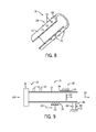
- FIG. 9 is a schematic diagram of an embodiment of a pulse detonation tube 10 having multiple couplings to a support structure 74.
- multiple pulse detonation tubes 10 may be supported within a pulse detonation combustor system.
- each tube 10 may be secured to a common support structure that transfers loads from the tubes 10 to a body of the combustor system.
- the couplings between the tubes 10 and the support structure 74 may serve to locally dissipate flexural wave energy.
- the couplings between the continuous base tube 12 and the tube support structure 74 may include a fixed coupling 76.
- the fixed coupling 76 substantially blocks movement of the continuous base tube 12 relative to the support structure 74.
- the fixed coupling 76 may transfer flexural wave energy from the pulse detonation tube 10 to the support structure 74, thereby interfering with the mechanical waves propagating through the tube 10 in the downstream direction 24 and substantially reducing or eliminating the possibility of establishing resonant coupling between the detonation wave 22 and the tube 10.
- the pulse detonation tube 10 may employ a roller coupling 78 to secure the continuous base tube 12 to the support structure 74.
- the roller coupling 78 substantially blocks lateral movement of the tube 10 relative to the support structure 74, while facilitating longitudinal expansion and contraction of the tube 12. Similar to the fixed coupling 76, the roller coupling 78 may transfer a portion of the flexural wave energy to the support structure 74, thereby interfering with the resonant coupling between the detonation wave 22 and the pulse detonation tube 10.
- the illustrated embodiment also includes a damped coupling 80 configured to damp movement of the continuous base tube 12 relative to the support structure 74.
- the damped coupling 80 includes a spring 82 and a dashpot 84. Because the damped coupling 80 is configured to absorb vibrational energy, the coupling 80 may interfere with the resonant coupling between the denotation wave 22 and the pulse detonation tube 10 by dissipating flexural wave energy. Consequently, strain within the tube 10 may be significantly lower than a tube having no damping feature.
- the illustrated embodiment includes a single fixed coupling 76, a single roller coupling 78 and a single damped coupling 80
- alternative embodiments may include other couplings secured to the downstream region 26 of the continuous base tube 12.
- certain embodiments may include a single fixed coupling 76, roller coupling 78 or damped coupling 80 secured to a downstream end of the tube 10.
- the pulse detonation tube may include multiple couplings, of the same type or of different types, secured to various positions along the length of the continuous base tube 12.
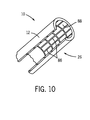
- FIG. 10 is a cross-sectional view of an embodiment of a pulse detonation tube 10 having multiple ridges 86 disposed on an interior surface 88 of the continuous base tube 12 proximate to the downstream region 26. Similar to the rings 64 and nubs 72 coupled to the exterior surface 66 of the continuous base tube 12, the ridges 86 are configured to locally dissipate flexural wave energy. Specifically, the ridges 86 will interfere with the flexural waves propagating through the tube 10 in the downstream direction 24, thereby substantially reducing or eliminating the possibility of establishing resonant coupling between the detonation wave 22 and the tube 10. Consequently, strain within the tube 10 will be significantly lower than a tube having a substantially smooth interior surface.
- the ridges 86 are integral with the continuous base tube 12.
- alternative embodiments may include ridges coupled to the interior 88 of the continuous base tube 12.
- the number, orientation, height and/or shape of the ridges may vary in alternative embodiments to achieve a desired degree of flexural wave dissipation.
- Certain pulse detonation tubes 10 include internal features configured to accelerate the flow through the tube 10, thereby inducing a deflagration to detonation transition (DDT).
- the ridges 86 may be configured to locally dissipate flexural wave energy in addition to accelerating the flow to induce DDT.
- the ridges 86 may extend into the upstream region 18 to facilitate DDT.
- each flexural wave modifying feature may be integral with the continuous base tube or coupled to the continuous base tube.
Landscapes
- Engineering & Computer Science (AREA)
- Chemical & Material Sciences (AREA)
- Combustion & Propulsion (AREA)
- Mechanical Engineering (AREA)
- General Engineering & Computer Science (AREA)
- Fluidized-Bed Combustion And Resonant Combustion (AREA)
- Combustion Of Fluid Fuel (AREA)
- Incineration Of Waste (AREA)
Applications Claiming Priority (1)
| Application Number | Priority Date | Filing Date | Title |
|---|---|---|---|
| US12/895,368 US8707674B2 (en) | 2010-09-30 | 2010-09-30 | Pulse detonation tube with local flexural wave modifying feature |
Publications (1)
| Publication Number | Publication Date |
|---|---|
| EP2436903A2 true EP2436903A2 (en) | 2012-04-04 |
Family
ID=44677753
Family Applications (1)
| Application Number | Title | Priority Date | Filing Date |
|---|---|---|---|
| EP11183082A Withdrawn EP2436903A2 (en) | 2010-09-30 | 2011-09-28 | Pulse detonation tube with local flexural wave modifying feature |
Country Status (4)
| Country | Link |
|---|---|
| US (1) | US8707674B2 (enExample) |
| EP (1) | EP2436903A2 (enExample) |
| JP (1) | JP6176772B2 (enExample) |
| CA (1) | CA2753033A1 (enExample) |
Families Citing this family (19)
| Publication number | Priority date | Publication date | Assignee | Title |
|---|---|---|---|---|
| WO2012061742A1 (en) | 2010-11-05 | 2012-05-10 | ThermoChem Recovery International | Solids circulation system and method for capture and conversion of reactive solids |
| US9499404B2 (en) | 2011-09-27 | 2016-11-22 | Thermochem Recovery International, Inc. | System and method for syngas clean-up |
| CN103953459B (zh) * | 2014-04-21 | 2016-06-08 | 西北工业大学 | 一种短距起爆高频爆震波的装置及其控制方法 |
| ES2940894T3 (es) | 2016-02-16 | 2023-05-12 | Thermochem Recovery Int Inc | Sistema y método de generación de gas producto de energía integrada de dos etapas |
| WO2017164888A1 (en) | 2016-03-25 | 2017-09-28 | Thermochem Recovery International, Inc. | Three-stage energy-integrated product gas generation system and method |
| US10364398B2 (en) | 2016-08-30 | 2019-07-30 | Thermochem Recovery International, Inc. | Method of producing product gas from multiple carbonaceous feedstock streams mixed with a reduced-pressure mixing gas |
| US10627111B2 (en) | 2017-03-27 | 2020-04-21 | United Technologies Coproration | Rotating detonation engine multi-stage mixer |
| US10436110B2 (en) | 2017-03-27 | 2019-10-08 | United Technologies Corporation | Rotating detonation engine upstream wave arrestor |
| US9920926B1 (en) | 2017-07-10 | 2018-03-20 | Thermochem Recovery International, Inc. | Pulse combustion heat exchanger system and method |
| US10099200B1 (en) | 2017-10-24 | 2018-10-16 | Thermochem Recovery International, Inc. | Liquid fuel production system having parallel product gas generation |
| RU2684352C1 (ru) * | 2018-07-16 | 2019-04-08 | Общество С Ограниченной Ответственностью "Пульсирующие Детонационные Технологии" | Регулируемое пульсирующее газодинамическое детонационное резонаторное выходное устройство для получения тяги |
| CN109915281B (zh) * | 2019-03-06 | 2021-03-19 | 西北工业大学 | 一种有益于壁面冷却与起爆的脉冲爆震火箭发动机供油方案 |
| US11555157B2 (en) | 2020-03-10 | 2023-01-17 | Thermochem Recovery International, Inc. | System and method for liquid fuel production from carbonaceous materials using recycled conditioned syngas |
| RU2742319C1 (ru) * | 2020-07-17 | 2021-02-04 | Федеральное государственное унитарное предприятие "Центральный институт авиационного моторостроения имени П.И. Баранова" | Способ работы детонационного ракетного двигателя |
| US11466223B2 (en) | 2020-09-04 | 2022-10-11 | Thermochem Recovery International, Inc. | Two-stage syngas production with separate char and product gas inputs into the second stage |
| CN113153570B (zh) * | 2021-05-27 | 2023-09-22 | 中国航空发动机研究院 | 一种脉冲爆震管性能计算方法和装置 |
| RU207457U1 (ru) * | 2021-07-26 | 2021-10-28 | Общество С Ограниченной Ответственностью "Пульсирующие Детонационные Технологии" | Выходное устройство двигателя прямой реакции |
| CN115822812B (zh) * | 2022-12-21 | 2024-11-26 | 西北工业大学 | 脉冲爆震发动机多孔促爆主爆震室及促爆方法 |
| CN119354406B (zh) * | 2024-10-22 | 2025-12-19 | 西北工业大学 | 一种固定爆震波曲率损失的装置与方法 |
Family Cites Families (35)
| Publication number | Priority date | Publication date | Assignee | Title |
|---|---|---|---|---|
| US866330A (en) * | 1906-11-24 | 1907-09-17 | Almeron E Calkins | Motor. |
| US1035454A (en) * | 1909-03-29 | 1912-08-13 | Isaac N Lewis | Internal-combustion power apparatus. |
| US1980266A (en) * | 1931-02-07 | 1934-11-13 | Robert H Goddard | Propulsion apparatus |
| US1856552A (en) * | 1931-06-26 | 1932-05-03 | Hadamik Frank | Carbide rocket |
| US2523379A (en) * | 1945-11-28 | 1950-09-26 | Kollsman Paul | Combustion products generator with combustion type precompressor |
| US2601471A (en) * | 1947-05-22 | 1952-06-24 | Vang Alfred | Jet propulsion means having vibrator therein |
| US2677232A (en) * | 1948-06-05 | 1954-05-04 | Continental Aviat & Engineerin | Combination pulse jet and ram jet engine |
| US2834181A (en) * | 1950-10-07 | 1958-05-13 | Snecma | Jet propulsion unit comprising pulse jet units having ejector tubes within a ramjet unit |
| US2799136A (en) * | 1951-04-09 | 1957-07-16 | Phillips Petroleum Co | Flame detection and control in aircraft engines |
| US2860484A (en) * | 1956-06-04 | 1958-11-18 | Schmidt Paul | Apparatus for causing intermittent combustion of a fuel in a chamber as a means of producing useful energy |
| US3210930A (en) * | 1962-02-01 | 1965-10-12 | Atlantic Res Corp | Gas generator |
| US3188805A (en) * | 1963-02-14 | 1965-06-15 | Charles L Gahagan | Internal combustion engine |
| US3293852A (en) * | 1963-03-19 | 1966-12-27 | Boeing Co | Plasma propulsion method and means |
| US3264824A (en) * | 1964-10-16 | 1966-08-09 | Warren J Bost | Pulse jet reaction motor having intermittent combustion |
| US3449913A (en) * | 1968-01-29 | 1969-06-17 | John J Grebe | Combustion process |
| JPH10141430A (ja) * | 1996-11-06 | 1998-05-29 | Toshiba Corp | 器具載置塔 |
| US6347509B1 (en) * | 1999-07-15 | 2002-02-19 | Mcdonnell Douglas Corporation C/O The Boeing Company | Pulsed detonation engine with ejector bypass |
| US6584765B1 (en) * | 2001-12-21 | 2003-07-01 | United Technologies Corporation | Pulse detonation engine having an aerodynamic valve |
| US6877310B2 (en) * | 2002-03-27 | 2005-04-12 | General Electric Company | Shock wave reflector and detonation chamber |
| US7055308B2 (en) * | 2003-05-30 | 2006-06-06 | General Electric Company | Detonation damper for pulse detonation engines |
| JP4411050B2 (ja) * | 2003-10-29 | 2010-02-10 | 東邦瓦斯株式会社 | ガスタービン装置 |
| US6983586B2 (en) * | 2003-12-08 | 2006-01-10 | General Electric Company | Two-stage pulse detonation system |
| GB0409664D0 (en) * | 2004-04-30 | 2004-06-02 | Denne William A | Ultrasonic pulse jet engine |
| US20050279083A1 (en) * | 2004-06-18 | 2005-12-22 | General Electric Company | Folded detonation initiator for constant volume combustion device |
| US7818956B2 (en) * | 2005-05-13 | 2010-10-26 | General Electric Company | Pulse detonation assembly and hybrid engine |
| US7828546B2 (en) * | 2005-06-30 | 2010-11-09 | General Electric Company | Naturally aspirated fluidic control for diverting strong pressure waves |
| US7669405B2 (en) * | 2005-12-22 | 2010-03-02 | General Electric Company | Shaped walls for enhancement of deflagration-to-detonation transition |
| US20090320439A1 (en) * | 2006-01-31 | 2009-12-31 | General Electric Company | Pulsed detonation combustor cleaning device and method of operation |
| US7966803B2 (en) * | 2006-02-03 | 2011-06-28 | General Electric Company | Pulse detonation combustor with folded flow path |
| JP2008202906A (ja) * | 2007-02-22 | 2008-09-04 | General Electric Co <Ge> | パルスデトネーション燃焼器清浄化装置および運転方法 |
| JP2008272622A (ja) * | 2007-04-26 | 2008-11-13 | Tama Tlo Kk | 溶射装置 |
| JP5142873B2 (ja) * | 2008-07-29 | 2013-02-13 | カヤバ工業株式会社 | 緩衝器 |
| US20110302904A1 (en) * | 2010-06-11 | 2011-12-15 | General Electric Company | Pulsed Detonation Cleaning Device with Multiple Folded Flow Paths |
| US8881500B2 (en) * | 2010-08-31 | 2014-11-11 | General Electric Company | Duplex tab obstacles for enhancement of deflagration-to-detonation transition |
| US20120192545A1 (en) * | 2011-01-28 | 2012-08-02 | General Electric Company | Pulse Detonation Combustor Nozzles |
-
2010
- 2010-09-30 US US12/895,368 patent/US8707674B2/en active Active
-
2011
- 2011-09-22 CA CA2753033A patent/CA2753033A1/en not_active Abandoned
- 2011-09-26 JP JP2011208870A patent/JP6176772B2/ja not_active Expired - Fee Related
- 2011-09-28 EP EP11183082A patent/EP2436903A2/en not_active Withdrawn
Non-Patent Citations (1)
| Title |
|---|
| None |
Also Published As
| Publication number | Publication date |
|---|---|
| JP6176772B2 (ja) | 2017-08-09 |
| US20120079806A1 (en) | 2012-04-05 |
| CA2753033A1 (en) | 2012-03-30 |
| US8707674B2 (en) | 2014-04-29 |
| JP2012078083A (ja) | 2012-04-19 |
Similar Documents
| Publication | Publication Date | Title |
|---|---|---|
| US8707674B2 (en) | Pulse detonation tube with local flexural wave modifying feature | |
| US9140456B2 (en) | Variable initiation location system for pulse detonation combustor | |
| US7526912B2 (en) | Pulse detonation engines and components thereof | |
| US20110047962A1 (en) | Pulse detonation combustor configuration for deflagration to detonation transition enhancement | |
| US8650856B2 (en) | Fluidic deflagration-to-detonation initiation obstacles | |
| US20120204534A1 (en) | System and method for damping pressure oscillations within a pulse detonation engine | |
| US8539752B2 (en) | Integrated deflagration-to-detonation obstacles and cooling fluid flow | |
| US8544280B2 (en) | Continuous detonation wave engine with quenching structure | |
| US6983586B2 (en) | Two-stage pulse detonation system | |
| US7669405B2 (en) | Shaped walls for enhancement of deflagration-to-detonation transition | |
| US9027324B2 (en) | Engine and combustion system | |
| JP6082576B2 (ja) | パルスデトネーション燃焼器のための可変開始位置特定システム | |
| EP2336523A2 (en) | Pulse detonation system with fuel lean inlet region | |
| US20200149496A1 (en) | Rotating detonation combustor with contoured inlet | |
| US20120102916A1 (en) | Pulse Detonation Combustor Including Combustion Chamber Cooling Assembly | |
| RU2125174C1 (ru) | Ракетный двигатель твердого топлива | |
| Allgood et al. | Performance studies of pulse detonation engine ejectors | |
| US11371711B2 (en) | Rotating detonation combustor with offset inlet | |
| Sada et al. | Numerical Investigation on Throatless Diverging Rotating Detonation Engines | |
| US12234773B1 (en) | Acoustically absorptive liners for passive control of unwanted acoustic modes in rotating detonation combustors | |
| Trefny et al. | Dual-mode free-jet combustor | |
| Murthy et al. | Flow Characteristics of High-Speed Co-flow Jets | |
| Khalatov et al. | PULSED DETONATION ENGINES: CURRENT STATE AND RESEARCH RESULTS. | |
| Tangirala et al. | Pulse detonation engines and components thereof |
Legal Events
| Date | Code | Title | Description |
|---|---|---|---|
| PUAI | Public reference made under article 153(3) epc to a published international application that has entered the european phase |
Free format text: ORIGINAL CODE: 0009012 |
|
| AK | Designated contracting states |
Kind code of ref document: A2 Designated state(s): AL AT BE BG CH CY CZ DE DK EE ES FI FR GB GR HR HU IE IS IT LI LT LU LV MC MK MT NL NO PL PT RO RS SE SI SK SM TR |
|
| AX | Request for extension of the european patent |
Extension state: BA ME |
|
| STAA | Information on the status of an ep patent application or granted ep patent |
Free format text: STATUS: THE APPLICATION IS DEEMED TO BE WITHDRAWN |
|
| 18D | Application deemed to be withdrawn |
Effective date: 20180404 |