EP2436802A1 - Structure of substrate supporting table, and plasma processing apparatus - Google Patents
Structure of substrate supporting table, and plasma processing apparatus Download PDFInfo
- Publication number
- EP2436802A1 EP2436802A1 EP10780508A EP10780508A EP2436802A1 EP 2436802 A1 EP2436802 A1 EP 2436802A1 EP 10780508 A EP10780508 A EP 10780508A EP 10780508 A EP10780508 A EP 10780508A EP 2436802 A1 EP2436802 A1 EP 2436802A1
- Authority
- EP
- European Patent Office
- Prior art keywords
- bellows
- end portion
- attached
- inner tube
- outer tube
- Prior art date
- Legal status (The legal status is an assumption and is not a legal conclusion. Google has not performed a legal analysis and makes no representation as to the accuracy of the status listed.)
- Withdrawn
Links
Images

Classifications
-
- C—CHEMISTRY; METALLURGY
- C23—COATING METALLIC MATERIAL; COATING MATERIAL WITH METALLIC MATERIAL; CHEMICAL SURFACE TREATMENT; DIFFUSION TREATMENT OF METALLIC MATERIAL; COATING BY VACUUM EVAPORATION, BY SPUTTERING, BY ION IMPLANTATION OR BY CHEMICAL VAPOUR DEPOSITION, IN GENERAL; INHIBITING CORROSION OF METALLIC MATERIAL OR INCRUSTATION IN GENERAL
- C23C—COATING METALLIC MATERIAL; COATING MATERIAL WITH METALLIC MATERIAL; SURFACE TREATMENT OF METALLIC MATERIAL BY DIFFUSION INTO THE SURFACE, BY CHEMICAL CONVERSION OR SUBSTITUTION; COATING BY VACUUM EVAPORATION, BY SPUTTERING, BY ION IMPLANTATION OR BY CHEMICAL VAPOUR DEPOSITION, IN GENERAL
- C23C16/00—Chemical coating by decomposition of gaseous compounds, without leaving reaction products of surface material in the coating, i.e. chemical vapour deposition [CVD] processes
- C23C16/44—Chemical coating by decomposition of gaseous compounds, without leaving reaction products of surface material in the coating, i.e. chemical vapour deposition [CVD] processes characterised by the method of coating
- C23C16/4401—Means for minimising impurities, e.g. dust, moisture or residual gas, in the reaction chamber
-
- C—CHEMISTRY; METALLURGY
- C23—COATING METALLIC MATERIAL; COATING MATERIAL WITH METALLIC MATERIAL; CHEMICAL SURFACE TREATMENT; DIFFUSION TREATMENT OF METALLIC MATERIAL; COATING BY VACUUM EVAPORATION, BY SPUTTERING, BY ION IMPLANTATION OR BY CHEMICAL VAPOUR DEPOSITION, IN GENERAL; INHIBITING CORROSION OF METALLIC MATERIAL OR INCRUSTATION IN GENERAL
- C23C—COATING METALLIC MATERIAL; COATING MATERIAL WITH METALLIC MATERIAL; SURFACE TREATMENT OF METALLIC MATERIAL BY DIFFUSION INTO THE SURFACE, BY CHEMICAL CONVERSION OR SUBSTITUTION; COATING BY VACUUM EVAPORATION, BY SPUTTERING, BY ION IMPLANTATION OR BY CHEMICAL VAPOUR DEPOSITION, IN GENERAL
- C23C16/00—Chemical coating by decomposition of gaseous compounds, without leaving reaction products of surface material in the coating, i.e. chemical vapour deposition [CVD] processes
- C23C16/44—Chemical coating by decomposition of gaseous compounds, without leaving reaction products of surface material in the coating, i.e. chemical vapour deposition [CVD] processes characterised by the method of coating
-
- H—ELECTRICITY
- H01—ELECTRIC ELEMENTS
- H01J—ELECTRIC DISCHARGE TUBES OR DISCHARGE LAMPS
- H01J37/00—Discharge tubes with provision for introducing objects or material to be exposed to the discharge, e.g. for the purpose of examination or processing thereof
- H01J37/32—Gas-filled discharge tubes
- H01J37/32431—Constructional details of the reactor
- H01J37/32532—Electrodes
- H01J37/32568—Relative arrangement or disposition of electrodes; moving means
-
- H—ELECTRICITY
- H10—SEMICONDUCTOR DEVICES; ELECTRIC SOLID-STATE DEVICES NOT OTHERWISE PROVIDED FOR
- H10P—GENERIC PROCESSES OR APPARATUS FOR THE MANUFACTURE OR TREATMENT OF DEVICES COVERED BY CLASS H10
- H10P50/00—Etching of wafers, substrates or parts of devices
- H10P50/20—Dry etching; Plasma etching; Reactive-ion etching
- H10P50/24—Dry etching; Plasma etching; Reactive-ion etching of semiconductor materials
- H10P50/242—Dry etching; Plasma etching; Reactive-ion etching of semiconductor materials of Group IV materials
-
- H—ELECTRICITY
- H10—SEMICONDUCTOR DEVICES; ELECTRIC SOLID-STATE DEVICES NOT OTHERWISE PROVIDED FOR
- H10P—GENERIC PROCESSES OR APPARATUS FOR THE MANUFACTURE OR TREATMENT OF DEVICES COVERED BY CLASS H10
- H10P72/00—Handling or holding of wafers, substrates or devices during manufacture or treatment thereof
- H10P72/70—Handling or holding of wafers, substrates or devices during manufacture or treatment thereof for supporting or gripping
-
- H—ELECTRICITY
- H10—SEMICONDUCTOR DEVICES; ELECTRIC SOLID-STATE DEVICES NOT OTHERWISE PROVIDED FOR
- H10P—GENERIC PROCESSES OR APPARATUS FOR THE MANUFACTURE OR TREATMENT OF DEVICES COVERED BY CLASS H10
- H10P72/00—Handling or holding of wafers, substrates or devices during manufacture or treatment thereof
- H10P72/70—Handling or holding of wafers, substrates or devices during manufacture or treatment thereof for supporting or gripping
- H10P72/76—Handling or holding of wafers, substrates or devices during manufacture or treatment thereof for supporting or gripping using mechanical means, e.g. clamps or pinches
- H10P72/7604—Handling or holding of wafers, substrates or devices during manufacture or treatment thereof for supporting or gripping using mechanical means, e.g. clamps or pinches the wafers being placed on a susceptor, stage or support
- H10P72/7624—Handling or holding of wafers, substrates or devices during manufacture or treatment thereof for supporting or gripping using mechanical means, e.g. clamps or pinches the wafers being placed on a susceptor, stage or support characterised by the mechanical construction of the susceptor, stage or support
-
- H—ELECTRICITY
- H10—SEMICONDUCTOR DEVICES; ELECTRIC SOLID-STATE DEVICES NOT OTHERWISE PROVIDED FOR
- H10P—GENERIC PROCESSES OR APPARATUS FOR THE MANUFACTURE OR TREATMENT OF DEVICES COVERED BY CLASS H10
- H10P72/00—Handling or holding of wafers, substrates or devices during manufacture or treatment thereof
- H10P72/70—Handling or holding of wafers, substrates or devices during manufacture or treatment thereof for supporting or gripping
- H10P72/76—Handling or holding of wafers, substrates or devices during manufacture or treatment thereof for supporting or gripping using mechanical means, e.g. clamps or pinches
- H10P72/7604—Handling or holding of wafers, substrates or devices during manufacture or treatment thereof for supporting or gripping using mechanical means, e.g. clamps or pinches the wafers being placed on a susceptor, stage or support
- H10P72/7626—Handling or holding of wafers, substrates or devices during manufacture or treatment thereof for supporting or gripping using mechanical means, e.g. clamps or pinches the wafers being placed on a susceptor, stage or support characterised by the construction of the shaft
Definitions
- the present invention relates to a structure of a substrate supporting table which supports a substrate on an upper surface thereof and which is vertically moveable, and also to a plasma processing apparatus having the structure of the substrate supporting table.
- Patent Documents 1, 2 an apparatus capable of changing the position of a substrate to be processed is known as a conventional art (Patent Documents 1, 2).
- plasma processing apparatuses for manufacturing a semiconductor device specifically, plasma CVD (Chemical Vapor Deposition) apparatuses and plasma etching apparatuses
- an apparatus including a substrate supporting table capable of adjusting the position of a substrate against plasma In such a plasma processing apparatus, a processing rate, an in-plane uniformity, and plasma damage can be adjusted to desired states by adjusting the distance between the substrate and the plasma.
- a plasma processing apparatus with a higher degree of freedom is achieved.
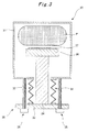
- Fig. 3 shows a cross-sectional view of a conventional plasma processing apparatus, and problems of the conventional plasma processing apparatus will be described together with the outline thereof. Note that, illustrations of a plasma generation mechanism, a gas supplying mechanism, a vacuum mechanism, and the like are omitted in Fig. 3 .
- a substrate 37 is placed on a placing table 36 disposed inside a vacuum chamber 31, and desired plasma processing is performed on the substrate 37 by using plasma P generated in the vacuum chamber 31.
- the position of the substrate 37 during the plasma processing is adjustable against the plasma P by a drive mechanism 38.
- the drive mechanism 38 includes: a drive member 34 which supports the placing table 36 from below; a drive plate 33 which supports the drive member 34; and multiple ball screws 35 by which the drive plate 33 is supported moveably.
- the drive plate 33, the drive member 34, the placing table 36, and the substrate 37 are vertically moved by rotating the ball screws 35, so that the position of the substrate 37 against the plasma P is adjusted.
- a bellows 32 is provided between a bottom portion of the vacuum chamber 31 and the drive plate 33. The bellows 32 allows the vertical movement of the drive mechanism 38 while maintaining a vacuum inside the vacuum chamber 31.
- the conventional plasma processing apparatus 30 has a structure in which the bellows 32 is disposed at a position directly below the placing table 36.
- Such a structure has the following problems.
- the present invention is made in view of the problems described above, and an object thereof is to provide a structure of a substrate supporting table and a plasma processing apparatus in which corrosion of a bellows and generation of particles from the bellows are suppressed and also a driven portion is reduced in volume and weight.
- a structure of a substrate supporting table according to a first invention for solving the above problems is a structure of a substrate supporting table which is used in a processing apparatus using a corrosive gas in a vacuum chamber, and which includes a drive mechanism to change a position of a substrate to be processed, the structure comprising:
- a structure of a substrate supporting table according to a second invention for solving the above problems is a structure of a substrate supporting table which is used in a processing apparatus using a corrosive gas in a vacuum chamber, and which includes a drive mechanism to change a position of a substrate to be processed, the structure comprising:
- a driven portion driven by the drive member includes members between the bellows and the placing table; that is, only the bellows, the outer tube, the cover member, and the placing table are driven.
- a structure of a substrate supporting table according to a third invention for solving the above problems is the structure of the substrate supporting table according to the first or second invention, wherein at least one of bonding of the inner tube and the bellows, which is performed instead of using the second sealing member, and bonding of the bellows and the outer tube, which is performed instead of using the third sealing member, is performed.
- a structure of a substrate supporting table according to a fourth invention for solving the above problems is the structure of the substrate supporting table according to any one of the first to third inventions, wherein a cylindrical exterior member made of a corrosion resistant material is further provided on an outer circumferential side of the cover member to cover an entire surface of the cover member.
- a structure of a substrate supporting table according to a fifth invention for solving the above problems is the structure of the substrate supporting table according to any one of the first to fourth inventions, wherein the processing apparatus is a plasma processing apparatus.
- a plasma processing device according to a sixth invention for solving the above problems is a plasma processing device comprising the structure of the substrate supporting table according to any one of the first to fourth inventions.
- the inner tube, the bellows, the outer tube, and the cover member are disposed concentrically in this order from the inner side.
- the bellows is protected by the outer tube and the cover member, and are therefore less likely to be exposed to a corrosive gas.
- corrosion of the bellows can be suppressed, and metal contamination due to the corrosion can be also suppressed.
- the temperature of the placing table is controlled to be a high temperature of, for example, 400°C, there has been a possibility of high temperature corrosion of the bellows.
- the outer tube and the cover member exist between the placing table and the bellows, the temperature of the bellows itself does not rise to a high temperature.
- a driven portion driven by the drive member includes only the bellows, the outer tube, the cover member, and the placing table.
- the volume and weight of the driven portion can be reduced compared to a conventional one.
- loads on the bellows and the drive mechanism can be reduced.
- the bellows deforms in the direction to contract.
- the bellows does not expand and break, and the safety of the apparatus can be secured.
- the exterior member having corrosion resistance is further provided on the outer circumferential side of the cover member.
- the corrosion of the bellows can be further suppressed.
- the structure of the substrate supporting table of any one of the first to fourth inventions is applied to a plasma processing apparatus.
- products from the plasma processing are less likely to adhere to the surface of the bellows, protected inside the outer tube, the cover member, and the like.
- the bellows expands and contracts, particles itself are generated less.
- a plasma CVD apparatus is given as an example in this description.
- the present invention is applicable not only to the plasma CVD apparatus but also to a plasma etching apparatus, and is also applicable to any other processing apparatus which moves a supporting table supporting an object to be processed in a vacuum chamber and which uses a corrosive gas in the vacuum chamber.
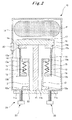
- Figs. 1 and 2 are cross-sectional views showing an example of the embodiment of the structure of the substrate supporting table of the present invention.
- Fig. 1 illustrates the substrate supporting table at a lower position in a plasma CVD apparatus
- Fig. 2 illustrates the substrate supporting table at an upper position. Note that, illustrations of a plasma generation mechanism, a gas supplying mechanism, a vacuum mechanism, and the like are omitted in Figs. 1 and 2 .
- a plasma processing apparatus 10 includes a vacuum chamber 11 in which a vacuum is created, and a disc-shaped placing table 16 which is disposed inside the vacuum chamber 11 and on which a substrate 17 is placed.
- the placing table 16 is supported by a supporting structure described below.
- the supporting structure includes a cylindrical inner tube 12, a bellows 13, and a cylindrical outer tube 14.
- the inner tube 12 has a lower flange 12a, which is a lower end portion (or one end portion) thereof, attached to a periphery of an opening 11b in a bottom portion 11a (or inner wall) of the vacuum chamber 11.
- the bellows 13 is disposed on the outer circumferential side of the inner tube 12, and has an upper flange 13a, which is an upper end portion (or one end portion) thereof, attached to an outer circumferential surface of an upper end portion (or the other end portion) of the inner tube 12.
- the outer tube 14 is disposed on the outer circumferential side of the bellows 13, and has a lower end portion (or one end portion) thereof attached to a lower flange 13b, which is a lower end portion (or the other end portion) of the bellows 13.
- the placing table 16 is attached to an upper flange 14a to close an opening in an upper end portion (or the other end portion) of the outer tube 14.
- a cover member 15 is provided on an outer circumference of the outer tube 14, the cover member 15 in tight contact with an outer circumference surface to cover the entire surface of the outer tube 14.
- a structure is provided in which, in a region directly below the placing table 16, the inner tube 12 is disposed on the innermost side, and the cylindrical inner tube 12, the bellows 13, the outer tube 14, and the cover member 15 being mutually different in diameter are disposed concentrically in this order from the inner side.
- the bottom portion 11a and the lower flange 12a are attached to each other with a sealing member (first sealing member) such as an O-ring in between.
- first sealing member such as an O-ring in between.
- second sealing member such as an O-ring in between
- third sealing member such as an O-ring in between
- fourth sealing member such as an O-ring in between
- fourth sealing member such as an O-ring in between
- This configuration allows a vertical movement of a drive mechanism 24 to be described later, while maintaining a vacuum inside the vacuum chamber 11.
- the bellows 13, and the outer tube 14 at least one of a pair of the inner tube 12 and the bellows 13 and a pair of the bellows 13 and the outer tube 14 may be bonded and integrated together by welding in a way that there is no leakage, so as to maintain a vacuum.
- the outer tube 14 is desirably made of a metal or an alloy having a relatively high melting point such for example as stainless steel to maintain the structure supporting the placing table 16 under a high temperature.
- the cover member 15 is made of a corrosion resistant material such for example as aluminum whose surface is anodized or a ceramics such as high-purity alumina to avoid high-temperature corrosion of the outer tube 14 by a corrosive gas. It is particularly desirable that a portion of the upper flange 14a in direct contact with the placing table 16 be in tight contact with the cover member 15 without a gap, since the placing table 16 is sometimes set to a high temperature of about 400°C.
- an upper end portion 15a of the cover member 15 is formed following conformity with the shape of the upper flange 14a, and put in tight contact without a gap. As a result, the outer tube 14 is exposed to the corrosive gas as little as possible.
- a cylindrical skirt member (exterior member) 18 may be provided on the outer circumferential side of the cover member 15 to cover the entire surface of the cover member 15.
- the skirt member 18 is made of a corrosion resistant material as similar to the cover member 15, and is made of, for example, aluminum whose surface is anodized or a ceramics such as a high-purity alumina. Provision of the skirt member 18 allows a gas flowing on the outer circumferential side of the skirt member 18 to be regulated, and also prevents the gas from moving toward the outer tube 14, the bellows 13, and the inner tube 12. As a result, corrosion of the outer tube 14, bellows 13, and inner tube 12 is prevented. Thus, metallic contamination due to the corrosion is prevented, and the product lives of these parts are extended.
- the placing table 16 can be vertically moved by the drive mechanism 24.
- the drive mechanism 24 includes: a drive member 21 which is attached to a back surface of the placing table 16 through the opening 11b and the inside of the inner tube 12; a drive plate 22 which supports the drive member 21; and multiple ball screws 23 by which the drive plate 22 is supported moveably.
- the drive plate 22, the drive member 21, the placing table 16, and the substrate 17 are vertically moved by rotating the ball screws 23, so that the position of the substrate 17 is changed.
- the placing table 16 When the substrate 17 is to be placed on the placing table 16, the placing table 16 is disposed at the lower position as shown in Fig. 1 , and the substrate 17 is placed through a gate door 20 by using an unillustrated robot arm. Meanwhile, when the substrate 17 placed on the placing table 16 is to be subjected to plasma processing, the placing table 16 is disposed at the upper position as shown in Fig. 2 , and the position against the plasma P is adjusted. Thus, plasma processing from which a desired processing result can be obtained is performed.
- the outer tube 14 is protected by the cover member 15. Therefore, even when the placing table 16 is heated to about 400°C, a high temperature portion is less likely to be exposed to the corrosive gas. Thus, high temperature corrosion is suppressed. Moreover, a path from the placing table 16 to the bellows 13 and a path from the placing table 16 to the inner tube 12 are long, so that heat is less likely to be transmitted. Thus, the inner tube 12 and the bellows 13 are not heated to a high temperature, and even if they are exposed to the corrosive gas, the high temperature corrosion is suppressed. Accordingly, in the inner tube 12, the bellows 13, and the outer tube 14 which are metal members, the high temperature corrosion of these members is suppressed, so that the product lives of these members are extended, and also the metal contamination caused by these members is suppressed.
- the bellows 13 is expanded when the substrate 17 is transported, and is contracted when the substrate 17 is subjected to plasma processing.
- products and by-products adhering to a surface of the bellows 13 are reduced.
- the plasma CVD apparatus since the formation of a film on the surface of the bellows 13 is reduced, generation of particles which is caused by the peeling of the formed thin film is reduced.
- the placing table 16 is provided with various parts such as: an electrostatic attraction electrode for electrostatically attracting the substrate 17; a bias electrode for applying a bias to the substrate 17; a heater for heating the substrate 17; a flow passage for a coolant to control the temperature of substrate 17; and a temperature sensor for detecting the temperatures of the substrate 17 and the placing table 16.
- an electrostatic attraction electrode for electrostatically attracting the substrate 17
- a bias electrode for applying a bias to the substrate 17
- a heater for heating the substrate 17
- a temperature sensor for detecting the temperatures of the substrate 17 and the placing table 16.
- the upper flange 13a of the bellows 13 divides the entirety into two sides: the placing table 16 side that is moved vertically; and the inner tube 12 side that is fixed.
- the placing table 16 side that is moved vertically
- the inner tube 12 side that is fixed.
- a pressure by atmospheric pressure may possibly be applied to the back surface of the placing table 16 due to failure of the drive mechanism 24 or the like, in which case the bellows 13 moves in the direction to contract. This is safer than a case where the bellows 13 moves in the direction to expand, and prevents the bellows 13 from breaking.
- the present invention is preferably applied to a plasma processing apparatus such as a plasma CVD apparatus or a plasma etching apparatus used to manufacture a semiconductor device.
- a plasma processing apparatus such as a plasma CVD apparatus or a plasma etching apparatus used to manufacture a semiconductor device.
- the present invention is not limited to the apparatus manufacturing a semiconductor device, and can be applied to an apparatus manufacturing other products, as long as the apparatus is one in which a bellows is used in a drive portion in a vacuum chamber and a corrosive gas is used on the bellows in the vacuum chamber.
Landscapes
- Chemical & Material Sciences (AREA)
- Engineering & Computer Science (AREA)
- Metallurgy (AREA)
- Chemical Kinetics & Catalysis (AREA)
- Materials Engineering (AREA)
- Mechanical Engineering (AREA)
- General Chemical & Material Sciences (AREA)
- Organic Chemistry (AREA)
- Physics & Mathematics (AREA)
- Plasma & Fusion (AREA)
- Analytical Chemistry (AREA)
- Container, Conveyance, Adherence, Positioning, Of Wafer (AREA)
- Drying Of Semiconductors (AREA)
- Chemical Vapour Deposition (AREA)
Abstract
Disclosed is the structure of a substrate supporting table wherein corrosion of a bellows is eliminated, generation of dusts from the bellows is suppressed, and the volume and the weight of the sections to be driven are reduced. A plasma processing apparatus is also disclosed. In the substrate supporting table for the plasma processing apparatus (10), a cylindrical inner tube (12), the bellows (13), an outer tube (14) and a cover member (15) are sequentially disposed concentrically from the inner side, and a drive member (21) to be driven by means of a drive mechanism (24) is attached to the rear surface of the placing table (16) through an opening (llb) and the inside of the inner tube (12).
Description
- The present invention relates to a structure of a substrate supporting table which supports a substrate on an upper surface thereof and which is vertically moveable, and also to a plasma processing apparatus having the structure of the substrate supporting table.
- Among processing apparatuses which perform desired processing in a vacuum, an apparatus capable of changing the position of a substrate to be processed is known as a conventional art (Patent Documents 1, 2). For example, among plasma processing apparatuses for manufacturing a semiconductor device, specifically, plasma CVD (Chemical Vapor Deposition) apparatuses and plasma etching apparatuses, there is known an apparatus including a substrate supporting table capable of adjusting the position of a substrate against plasma. In such a plasma processing apparatus, a processing rate, an in-plane uniformity, and plasma damage can be adjusted to desired states by adjusting the distance between the substrate and the plasma. Thus, a plasma processing apparatus with a higher degree of freedom is achieved.
- Patent Document 1: Japanese Patent Application Publication No.
2003-229408 - Patent Document 2: Japanese Patent Application Publication No.
2003-289068 -
Fig. 3 shows a cross-sectional view of a conventional plasma processing apparatus, and problems of the conventional plasma processing apparatus will be described together with the outline thereof. Note that, illustrations of a plasma generation mechanism, a gas supplying mechanism, a vacuum mechanism, and the like are omitted inFig. 3 .
As shown inFig. 3 , in a conventionalplasma processing apparatus 30, asubstrate 37 is placed on a placing table 36 disposed inside avacuum chamber 31, and desired plasma processing is performed on thesubstrate 37 by using plasma P generated in thevacuum chamber 31. The position of thesubstrate 37 during the plasma processing is adjustable against the plasma P by adrive mechanism 38. - Specifically, the
drive mechanism 38 includes: adrive member 34 which supports the placing table 36 from below; adrive plate 33 which supports thedrive member 34; andmultiple ball screws 35 by which thedrive plate 33 is supported moveably. Thedrive plate 33, thedrive member 34, the placing table 36, and thesubstrate 37 are vertically moved by rotating theball screws 35, so that the position of thesubstrate 37 against the plasma P is adjusted. Moreover, abellows 32 is provided between a bottom portion of thevacuum chamber 31 and thedrive plate 33. Thebellows 32 allows the vertical movement of thedrive mechanism 38 while maintaining a vacuum inside thevacuum chamber 31. - As shown in
Fig. 3 , the conventionalplasma processing apparatus 30 has a structure in which thebellows 32 is disposed at a position directly below the placing table 36. Such a structure, however, has the following problems. - (1) A bellows made of stainless steel is generally used. When the bellows is exposed to a corrosive gas in a high temperature state, corrosion thereof progresses, thereby shortening the life of the bellows and causing metal contamination. Particularly, in the plasma processing apparatus, the placing table is generally heated to a high temperature of about 400°C and a corrosive gas such as NF3, CF4, or SF6 is used as an etching gas (cleaning gas). Thus, the bellows is used in an environment in which corrosion is likely to occur.
- (2) To avoid corrosion, the bellows should be provided at a position distant from the corrosive gas and the high temperature portion. However, if the placing table and the bellows are distant from each other (see
Fig. 3 ), the volume and weight of a driven portion increases, and a large load is applied to the drive mechanism. In addition, if the volume and weight of the driven portion increases, the workability in maintenance is deteriorated, and the burden of maintenance is increased. - (3) Products from the plasma processing adhere to surfaces of the components inside the vacuum chamber. When the products adhere to a surface of the bellows, the adhered products are peeled off by the extraction and contraction of the bellows itself, and become a cause of particles.
- The present invention is made in view of the problems described above, and an object thereof is to provide a structure of a substrate supporting table and a plasma processing apparatus in which corrosion of a bellows and generation of particles from the bellows are suppressed and also a driven portion is reduced in volume and weight.
- A structure of a substrate supporting table according to a first invention for solving the above problems is a structure of a substrate supporting table which is used in a processing apparatus using a corrosive gas in a vacuum chamber, and which includes a drive mechanism to change a position of a substrate to be processed, the structure comprising:
- a cylindrical inner tube which has one end portion thereof attached to a periphery of an opening in an inner wall of the vacuum chamber with a first sealing member in between;
- a bellows which is disposed on an outer circumferential side of the inner tube, and which has one end portion thereof attached to another end portion of the inner tube with a second sealing member in between;
- a cylindrical outer tube which is disposed on a outer circumferential side of the bellows, and which has one end portion thereof attached to another end portion of the bellows with a third sealing member in between;
- a disc-shaped placing table which is attached to close an opening in another end portion of the outer tube with a fourth sealing member in between, and on which the substrate is placed;
- a cover member which is provided in tight contact with the outer tube to cover an entire surface of the outer tube, and which is made of a corrosion resistant material; and
- a drive member which is attached to a back surface of the placing table through the opening in the inner wall of the vacuum chamber and an inside of the inner tube, and which is driven by the drive mechanism.
- A structure of a substrate supporting table according to a second invention for solving the above problems is a structure of a substrate supporting table which is used in a processing apparatus using a corrosive gas in a vacuum chamber, and which includes a drive mechanism to change a position of a substrate to be processed, the structure comprising:
- a cylindrical inner tube which has a lower end portion thereof attached to a periphery of an opening in a bottom portion of the vacuum chamber with a first sealing member in between;
- a bellows which is disposed on an outer circumferential side of the inner tube, and which has an upper end portion thereof attached to an upper end portion of the inner tube with a second sealing member in between;
- a cylindrical outer tube which is disposed on an outer circumferential side of the bellows, and which has a lower end portion thereof attached to a lower end portion of the bellows with a third sealing member in between;
- a disc-shaped placing table which is attached to close an opening in an upper end portion of the outer tube with a fourth sealing member in between, and on which the substrate is placed;
- a cylindrical cover member which is provided in tight contact with the outer tube to cover an entire surface of the outer tube, and which is made of a corrosion resistant material; and
- a drive member which is attached to a back surface of the placing table through the opening in the inner wall of the vacuum chamber and an inside of the inner tube, and which is driven by the drive mechanism.
- Specifically, when any of the structures of the substrate supporting tables according to the first and second inventions described above is employed, the cylindrical inner tube, bellows, outer tube, and cover member are disposed concentrically in this order from the inner side while maintaining a vacuum in the vacuum chamber. Moreover, a driven portion driven by the drive member includes members between the bellows and the placing table; that is, only the bellows, the outer tube, the cover member, and the placing table are driven.
- A structure of a substrate supporting table according to a third invention for solving the above problems is the structure of the substrate supporting table according to the first or second invention, wherein at least one of bonding of the inner tube and the bellows, which is performed instead of using the second sealing member, and bonding of the bellows and the outer tube, which is performed instead of using the third sealing member, is performed.
- A structure of a substrate supporting table according to a fourth invention for solving the above problems is the structure of the substrate supporting table according to any one of the first to third inventions, wherein a cylindrical exterior member made of a corrosion resistant material is further provided on an outer circumferential side of the cover member to cover an entire surface of the cover member.
- A structure of a substrate supporting table according to a fifth invention for solving the above problems is the structure of the substrate supporting table according to any one of the first to fourth inventions, wherein the processing apparatus is a plasma processing apparatus.
Moreover, a plasma processing device according to a sixth invention for solving the above problems is a plasma processing device comprising the structure of the substrate supporting table according to any one of the first to fourth inventions. - In the first to third inventions, the inner tube, the bellows, the outer tube, and the cover member are disposed concentrically in this order from the inner side. Thus, the bellows is protected by the outer tube and the cover member, and are therefore less likely to be exposed to a corrosive gas. Hence, corrosion of the bellows can be suppressed, and metal contamination due to the corrosion can be also suppressed. Particularly, when the temperature of the placing table is controlled to be a high temperature of, for example, 400°C, there has been a possibility of high temperature corrosion of the bellows. However, since the outer tube and the cover member exist between the placing table and the bellows, the temperature of the bellows itself does not rise to a high temperature. Thus, the high temperature corrosion is suppressed and the metal contamination due to the high temperature corrosion is also suppressed. Moreover, a driven portion driven by the drive member includes only the bellows, the outer tube, the cover member, and the placing table. Thus, the volume and weight of the driven portion can be reduced compared to a conventional one. Hence, loads on the bellows and the drive mechanism can be reduced. In addition, in the case where the drive mechanism fails and the placing table is thereby pushed to the vacuum side by the atmosphere on the back-surface side of the placing table, the bellows deforms in the direction to contract. Thus, the bellows does not expand and break, and the safety of the apparatus can be secured. The above facts make it possible to improve the performance and reliability of the structure of the substrate supporting table.
- In the fourth invention, the exterior member having corrosion resistance is further provided on the outer circumferential side of the cover member. Thus, the corrosion of the bellows can be further suppressed.
- In the fifth and sixth invention, the structure of the substrate supporting table of any one of the first to fourth inventions is applied to a plasma processing apparatus. Thus, products from the plasma processing are less likely to adhere to the surface of the bellows, protected inside the outer tube, the cover member, and the like. Hence, when the bellows expands and contracts, particles itself are generated less.
-
- [
Fig. 1] Fig. 1 is a cross-sectional view showing an example of an embodiment of a structure of a substrate supporting table of the present invention, and illustrates the substrate supporting table moved to a lower position in a plasma CVD apparatus. - [
Fig. 2] Fig. 2 is a cross-sectional view showing the example of the embodiment of the structure of the substrate supporting table of the present invention, and illustrates the substrate supporting table moved to an upper position in the plasma CVD apparatus. - [
Fig. 3] Fig. 3 is a cross-sectional view of a conventional plasma processing apparatus. -
- 10
- PLASMA CVD APPARATUS
- 11
- VACUUM CHAMBER
- 12
- INNER TUBE
- 13
- BELLOWS
- 14
- OUTER TUBE
- 15
- COVER MEMBER
- 16
- PLACING TABLE
- 17
- SUBSTRATE
- 18
- SKIRL MEMBER
- 20
- GATE DOOR
- 21
- DRIVE MEMBER
- 22
- DRIVE PLATE
- 23
- BALL SCREW
- An embodiment of a structure of a substrate supporting table of the present invention will be described with reference to
Figs. 1 to 2 . Note that, a plasma CVD apparatus is given as an example in this description. However, the present invention is applicable not only to the plasma CVD apparatus but also to a plasma etching apparatus, and is also applicable to any other processing apparatus which moves a supporting table supporting an object to be processed in a vacuum chamber and which uses a corrosive gas in the vacuum chamber. -
Figs. 1 and2 are cross-sectional views showing an example of the embodiment of the structure of the substrate supporting table of the present invention.Fig. 1 illustrates the substrate supporting table at a lower position in a plasma CVD apparatus, whereasFig. 2 illustrates the substrate supporting table at an upper position. Note that, illustrations of a plasma generation mechanism, a gas supplying mechanism, a vacuum mechanism, and the like are omitted inFigs. 1 and2 . - In the embodiment, a
plasma processing apparatus 10 includes avacuum chamber 11 in which a vacuum is created, and a disc-shaped placing table 16 which is disposed inside thevacuum chamber 11 and on which asubstrate 17 is placed. - The placing table 16 is supported by a supporting structure described below. Specifically, the supporting structure includes a cylindrical
inner tube 12, a bellows 13, and a cylindricalouter tube 14. Theinner tube 12 has alower flange 12a, which is a lower end portion (or one end portion) thereof, attached to a periphery of anopening 11b in abottom portion 11a (or inner wall) of thevacuum chamber 11. The bellows 13 is disposed on the outer circumferential side of theinner tube 12, and has anupper flange 13a, which is an upper end portion (or one end portion) thereof, attached to an outer circumferential surface of an upper end portion (or the other end portion) of theinner tube 12. Theouter tube 14 is disposed on the outer circumferential side of thebellows 13, and has a lower end portion (or one end portion) thereof attached to alower flange 13b, which is a lower end portion (or the other end portion) of thebellows 13. The placing table 16 is attached to anupper flange 14a to close an opening in an upper end portion (or the other end portion) of theouter tube 14. Moreover, acover member 15 is provided on an outer circumference of theouter tube 14, thecover member 15 in tight contact with an outer circumference surface to cover the entire surface of theouter tube 14. In other words, a structure is provided in which, in a region directly below the placing table 16, theinner tube 12 is disposed on the innermost side, and the cylindricalinner tube 12, thebellows 13, theouter tube 14, and thecover member 15 being mutually different in diameter are disposed concentrically in this order from the inner side. - Moreover, the
bottom portion 11a and thelower flange 12a are attached to each other with a sealing member (first sealing member) such as an O-ring in between. Similarly, theinner tube 12 and theupper flange 13a are attached to each other with a sealing member (second sealing member) such as an O-ring in between; thelower flange 13b and theouter tube 14 are attached to each other with a sealing member (third sealing member) such as an O-ring in between; and theupper flange 14a and the placing table 16 are attached to each other with a sealing member (fourth sealing member) such as an O-ring in between. In other words, thevacuum chamber 11, theinner tube 12, thebellows 13, theouter tube 14, and the placing table 16 are attached to one another with a sealing member in between. This configuration allows a vertical movement of adrive mechanism 24 to be described later, while maintaining a vacuum inside thevacuum chamber 11. Note that, for theinner tube 12, thebellows 13, and theouter tube 14, at least one of a pair of theinner tube 12 and thebellows 13 and a pair of thebellows 13 and theouter tube 14 may be bonded and integrated together by welding in a way that there is no leakage, so as to maintain a vacuum. - Among the
inner tube 12, thebellows 13, and theouter tube 14, at least theouter tube 14 is desirably made of a metal or an alloy having a relatively high melting point such for example as stainless steel to maintain the structure supporting the placing table 16 under a high temperature. Moreover, thecover member 15 is made of a corrosion resistant material such for example as aluminum whose surface is anodized or a ceramics such as high-purity alumina to avoid high-temperature corrosion of theouter tube 14 by a corrosive gas. It is particularly desirable that a portion of theupper flange 14a in direct contact with the placing table 16 be in tight contact with thecover member 15 without a gap, since the placing table 16 is sometimes set to a high temperature of about 400°C. For example, if theupper flange 14a protrudes to an outer circumferential side thereof as shown inFigs. 1 and2 , anupper end portion 15a of thecover member 15 is formed following conformity with the shape of theupper flange 14a, and put in tight contact without a gap. As a result, theouter tube 14 is exposed to the corrosive gas as little as possible. - Note that, a cylindrical skirt member (exterior member) 18 may be provided on the outer circumferential side of the
cover member 15 to cover the entire surface of thecover member 15. Theskirt member 18 is made of a corrosion resistant material as similar to thecover member 15, and is made of, for example, aluminum whose surface is anodized or a ceramics such as a high-purity alumina. Provision of theskirt member 18 allows a gas flowing on the outer circumferential side of theskirt member 18 to be regulated, and also prevents the gas from moving toward theouter tube 14, thebellows 13, and theinner tube 12. As a result, corrosion of theouter tube 14, bellows 13, andinner tube 12 is prevented. Thus, metallic contamination due to the corrosion is prevented, and the product lives of these parts are extended. - The placing table 16 can be vertically moved by the
drive mechanism 24. Specifically, thedrive mechanism 24 includes: adrive member 21 which is attached to a back surface of the placing table 16 through theopening 11b and the inside of theinner tube 12; adrive plate 22 which supports thedrive member 21; and multiple ball screws 23 by which thedrive plate 22 is supported moveably. Thedrive plate 22, thedrive member 21, the placing table 16, and thesubstrate 17 are vertically moved by rotating the ball screws 23, so that the position of thesubstrate 17 is changed. - When the
substrate 17 is to be placed on the placing table 16, the placing table 16 is disposed at the lower position as shown inFig. 1 , and thesubstrate 17 is placed through agate door 20 by using an unillustrated robot arm. Meanwhile, when thesubstrate 17 placed on the placing table 16 is to be subjected to plasma processing, the placing table 16 is disposed at the upper position as shown inFig. 2 , and the position against the plasma P is adjusted. Thus, plasma processing from which a desired processing result can be obtained is performed. - In the structure described above, the
outer tube 14 is protected by thecover member 15. Therefore, even when the placing table 16 is heated to about 400°C, a high temperature portion is less likely to be exposed to the corrosive gas. Thus, high temperature corrosion is suppressed. Moreover, a path from the placing table 16 to thebellows 13 and a path from the placing table 16 to theinner tube 12 are long, so that heat is less likely to be transmitted. Thus, theinner tube 12 and thebellows 13 are not heated to a high temperature, and even if they are exposed to the corrosive gas, the high temperature corrosion is suppressed. Accordingly, in theinner tube 12, thebellows 13, and theouter tube 14 which are metal members, the high temperature corrosion of these members is suppressed, so that the product lives of these members are extended, and also the metal contamination caused by these members is suppressed. - Moreover, in the structure described above, the
bellows 13 is expanded when thesubstrate 17 is transported, and is contracted when thesubstrate 17 is subjected to plasma processing. Thus, products and by-products adhering to a surface of thebellows 13 are reduced. Particularly, in the plasma CVD apparatus, since the formation of a film on the surface of thebellows 13 is reduced, generation of particles which is caused by the peeling of the formed thin film is reduced. - Furthermore, in the structure described above, the back-surface side of the placing table 16 is at atmospheric pressure. In the plasma processing apparatus, the placing table 16 is provided with various parts such as: an electrostatic attraction electrode for electrostatically attracting the
substrate 17; a bias electrode for applying a bias to thesubstrate 17; a heater for heating thesubstrate 17; a flow passage for a coolant to control the temperature ofsubstrate 17; and a temperature sensor for detecting the temperatures of thesubstrate 17 and the placing table 16. By disposing connection portions of these parts at the atmospheric-pressure side, electric discharge can be prevented in portions to which a high voltage is applied such as the electrostatic attraction electrode, the bias electrode, and the heater. Moreover, in the connection portion to the flow passage, even if the coolant leaks, the leakage occurs in the atmosphere side. Thus, the inside of thevacuum chamber 11 is not contaminated. - Additionally, in the structure described above, the
upper flange 13a of thebellows 13 divides the entirety into two sides: the placing table 16 side that is moved vertically; and theinner tube 12 side that is fixed. Thus, it is possible to reduce the volume and weight of driven portions inside thevacuum chamber 11, and thus to reduce a load on thedrive mechanism 24. Moreover, a pressure by atmospheric pressure may possibly be applied to the back surface of the placing table 16 due to failure of thedrive mechanism 24 or the like, in which case thebellows 13 moves in the direction to contract. This is safer than a case where thebellows 13 moves in the direction to expand, and prevents thebellows 13 from breaking. - The present invention is preferably applied to a plasma processing apparatus such as a plasma CVD apparatus or a plasma etching apparatus used to manufacture a semiconductor device. However, the present invention is not limited to the apparatus manufacturing a semiconductor device, and can be applied to an apparatus manufacturing other products, as long as the apparatus is one in which a bellows is used in a drive portion in a vacuum chamber and a corrosive gas is used on the bellows in the vacuum chamber.
Claims (6)
- A structure of a substrate supporting table which is used in a processing apparatus using a corrosive gas in a vacuum chamber, and which includes a drive mechanism to change a position of a substrate to be processed, the structure comprising:a cylindrical inner tube which has one end portion thereof attached to a periphery of an opening in an inner wall of the vacuum chamber with a first sealing member in between;a bellows which is disposed on an outer circumferential side of the inner tube, and which has one end portion thereof attached to another end portion of the inner tube with a second sealing member in between;a cylindrical outer tube which is disposed on an outer circumferential side of the bellows, and which has one end portion thereof attached to another end portion of the bellows with a third sealing member in between;a disc-shaped placing table which is attached to close an opening in another end portion of the outer tube with a fourth sealing member in between, and on which the substrate is placed;a cover member which is provided in tight contact with the outer tube to cover an entire surface of the outer tube, and which is made of a corrosion resistant material; anda drive member which is attached to a back surface of the placing table through the opening in the inner wall of the vacuum chamber and an inside of the inner tube, and which is driven by the drive mechanism.
- A structure of a substrate supporting table which is used in a processing apparatus using a corrosive gas in a vacuum chamber, and which includes a drive mechanism to change a position of a substrate to be processed, the structure comprising:a cylindrical inner tube which has a lower end portion thereof attached to a periphery of an opening in a bottom portion of the vacuum chamber with a first sealing member in between;a bellows which is disposed on an outer circumferential side of the inner tube, and which has an upper end portion thereof attached to an upper end portion of the inner tube with a second sealing member in between;a cylindrical outer tube which is disposed on an outer circumferential side of the bellows, and which has a lower end portion thereof attached to a lower end portion of the bellows with a third sealing member in between;a disc-shaped placing table which is attached to close an opening in an upper end portion of the outer tube with a fourth sealing member in between, and on which the substrate is placed;a cylindrical cover member which is provided in tight contact with the outer tube to cover an entire surface of the outer tube, and which is made of a corrosion resistant material; anda drive member which is attached to a back surface of the placing table through the opening in the inner wall of the vacuum chamber and an inside of the inner tube, and which is driven by the drive mechanism.
- The structure of the substrate supporting table according to claim 1 or 2, wherein at least one of bonding of the inner tube and the bellows, which is performed instead of using the second sealing member, and bonding of the bellows and the outer tube, which is performed instead of using the third sealing member, is performed.
- The structure of the substrate supporting table according to any one of claims 1 to 3, wherein a cylindrical exterior member made of a corrosion resistant material is further provided on an outer circumferential side of the cover member to cover an entire surface of the cover member.
- The structure of the substrate supporting table according to any one of claims 1 to 4, wherein the processing apparatus is a plasma processing apparatus.
- A plasma processing device comprising the structure of the substrate supporting table according to any one of claims 1 to 4.
Applications Claiming Priority (2)
| Application Number | Priority Date | Filing Date | Title |
|---|---|---|---|
| JP2009129842A JP5398358B2 (en) | 2009-05-29 | 2009-05-29 | Substrate support structure and plasma processing apparatus |
| PCT/JP2010/058731 WO2010137553A1 (en) | 2009-05-29 | 2010-05-24 | Structure of substrate supporting table, and plasma processing apparatus |
Publications (1)
| Publication Number | Publication Date |
|---|---|
| EP2436802A1 true EP2436802A1 (en) | 2012-04-04 |
Family
ID=43222662
Family Applications (1)
| Application Number | Title | Priority Date | Filing Date |
|---|---|---|---|
| EP10780508A Withdrawn EP2436802A1 (en) | 2009-05-29 | 2010-05-24 | Structure of substrate supporting table, and plasma processing apparatus |
Country Status (6)
| Country | Link |
|---|---|
| US (1) | US20120111502A1 (en) |
| EP (1) | EP2436802A1 (en) |
| JP (1) | JP5398358B2 (en) |
| KR (1) | KR101367473B1 (en) |
| TW (1) | TWI463596B (en) |
| WO (1) | WO2010137553A1 (en) |
Families Citing this family (6)
| Publication number | Priority date | Publication date | Assignee | Title |
|---|---|---|---|---|
| KR101451736B1 (en) * | 2013-02-06 | 2014-10-16 | 주식회사 코디에스 | Plasma etching apparatus and device for substrate transfer |
| DE102014220220B4 (en) * | 2014-10-07 | 2018-05-30 | Carl Zeiss Smt Gmbh | Vacuum linear feedthrough and vacuum system with it |
| CN109424761B (en) * | 2017-08-31 | 2019-11-19 | 长鑫存储技术有限公司 | Isolation valve, semiconductor production equipment and cleaning method thereof |
| CN113000233B (en) * | 2019-12-18 | 2022-09-02 | 中微半导体设备(上海)股份有限公司 | Plasma reactor and gas nozzle thereof |
| CN114078680B (en) * | 2020-08-20 | 2023-09-29 | 中微半导体设备(上海)股份有限公司 | Plasma treatment equipment |
| CN115424913B (en) * | 2021-06-01 | 2025-05-09 | 中微半导体设备(上海)股份有限公司 | A plasma processing device and a retractable sealing part thereof |
Family Cites Families (15)
| Publication number | Priority date | Publication date | Assignee | Title |
|---|---|---|---|---|
| JPS63153263A (en) * | 1986-12-17 | 1988-06-25 | Mitsubishi Electric Corp | Vacuum treatment device |
| JPH05299385A (en) * | 1992-02-20 | 1993-11-12 | Matsushita Electron Corp | Electrode for plasma etching apparatus and the apparatus using the same |
| JP3172758B2 (en) * | 1993-11-20 | 2001-06-04 | 東京エレクトロン株式会社 | Plasma etching method |
| US5900103A (en) * | 1994-04-20 | 1999-05-04 | Tokyo Electron Limited | Plasma treatment method and apparatus |
| US6287435B1 (en) * | 1998-05-06 | 2001-09-11 | Tokyo Electron Limited | Method and apparatus for ionized physical vapor deposition |
| JP3662779B2 (en) * | 1999-06-22 | 2005-06-22 | シャープ株式会社 | Plasma processing equipment |
| JP2001077088A (en) * | 1999-09-02 | 2001-03-23 | Tokyo Electron Ltd | Plasma processing equipment |
| JP2002151473A (en) * | 2000-11-13 | 2002-05-24 | Tokyo Electron Ltd | Plasma processing apparatus and method of assembling the same |
| US20020148565A1 (en) * | 2001-04-12 | 2002-10-17 | Applied Materials, Inc. | Mushroom stem wafer pedestal for improved conductance and uniformity |
| JP4209618B2 (en) | 2002-02-05 | 2009-01-14 | 東京エレクトロン株式会社 | Plasma processing apparatus and ring member |
| JP4056855B2 (en) | 2002-01-22 | 2008-03-05 | 東京エレクトロン株式会社 | Surface treatment equipment |
| WO2003067636A1 (en) * | 2002-01-22 | 2003-08-14 | Tokyo Electron Limited | Surface treating device and surface treating method |
| US7204912B2 (en) * | 2002-09-30 | 2007-04-17 | Tokyo Electron Limited | Method and apparatus for an improved bellows shield in a plasma processing system |
| JP2005056994A (en) * | 2003-08-01 | 2005-03-03 | Saginomiya Seisakusho Inc | Plasma processing equipment |
| US7789963B2 (en) * | 2005-02-25 | 2010-09-07 | Tokyo Electron Limited | Chuck pedestal shield |
-
2009
- 2009-05-29 JP JP2009129842A patent/JP5398358B2/en not_active Expired - Fee Related
-
2010
- 2010-05-24 EP EP10780508A patent/EP2436802A1/en not_active Withdrawn
- 2010-05-24 US US13/319,906 patent/US20120111502A1/en not_active Abandoned
- 2010-05-24 KR KR1020117028277A patent/KR101367473B1/en not_active Expired - Fee Related
- 2010-05-24 WO PCT/JP2010/058731 patent/WO2010137553A1/en not_active Ceased
- 2010-05-27 TW TW099117023A patent/TWI463596B/en not_active IP Right Cessation
Non-Patent Citations (1)
| Title |
|---|
| See references of WO2010137553A1 * |
Also Published As
| Publication number | Publication date |
|---|---|
| TW201130078A (en) | 2011-09-01 |
| US20120111502A1 (en) | 2012-05-10 |
| JP2010275593A (en) | 2010-12-09 |
| WO2010137553A1 (en) | 2010-12-02 |
| TWI463596B (en) | 2014-12-01 |
| KR101367473B1 (en) | 2014-02-25 |
| JP5398358B2 (en) | 2014-01-29 |
| KR20120014182A (en) | 2012-02-16 |
Similar Documents
| Publication | Publication Date | Title |
|---|---|---|
| US20120111502A1 (en) | Structure of substrate supporting table, and plasma processing apparatus | |
| JP6054314B2 (en) | Method and apparatus for substrate transport and radical confinement | |
| CN101790786B (en) | Stage structure and handling device | |
| US8623172B2 (en) | Gas flow path structure and substrate processing apparatus | |
| KR102554832B1 (en) | Corrosion Control for Chamber Components | |
| JP5996340B2 (en) | Plasma etching equipment | |
| KR101316954B1 (en) | Substrate support stage of plasma processing apparatus | |
| US20140346152A1 (en) | Mounting table and plasma processing apparatus | |
| CN111566797A (en) | Lift Pin System for Wafer Handling | |
| TW200535940A (en) | High productivity plasma processing chamber | |
| CN1537328A (en) | High temperature electrostatic chuck | |
| JPWO2008156031A1 (en) | Vacuum processing equipment | |
| KR20080106115A (en) | Substrate processing apparatus having a substrate mounting mechanism and the substrate mounting mechanism | |
| CN109962031B (en) | Protected electrostatic chuck and application thereof | |
| JP5985316B2 (en) | Plasma etching equipment | |
| JP6753654B2 (en) | Plasma processing equipment | |
| EP2444997A1 (en) | Plasma processing apparatus and plasma processing method | |
| JP2001223258A (en) | Wafer holding device | |
| JP6030404B2 (en) | Sputtering equipment | |
| JP7645282B2 (en) | Electrostatic clamping system and method | |
| JP5743120B2 (en) | Plasma processing apparatus and method | |
| CN121549091A (en) | Components with power supply terminal parts | |
| KR20240165553A (en) | Substrate support apparatus and substrate processing apparatus having the same | |
| JP2008147420A (en) | Substrate processing equipment |
Legal Events
| Date | Code | Title | Description |
|---|---|---|---|
| PUAI | Public reference made under article 153(3) epc to a published international application that has entered the european phase |
Free format text: ORIGINAL CODE: 0009012 |
|
| 17P | Request for examination filed |
Effective date: 20111128 |
|
| AK | Designated contracting states |
Kind code of ref document: A1 Designated state(s): AL AT BE BG CH CY CZ DE DK EE ES FI FR GB GR HR HU IE IS IT LI LT LU LV MC MK MT NL NO PL PT RO SE SI SK SM TR |
|
| DAX | Request for extension of the european patent (deleted) | ||
| STAA | Information on the status of an ep patent application or granted ep patent |
Free format text: STATUS: THE APPLICATION HAS BEEN WITHDRAWN |
|
| 18W | Application withdrawn |
Effective date: 20130122 |