EP2435236B1 - Positioniereinrichtung für ein handschweissgerät - Google Patents
Positioniereinrichtung für ein handschweissgerät Download PDFInfo
- Publication number
- EP2435236B1 EP2435236B1 EP10732268A EP10732268A EP2435236B1 EP 2435236 B1 EP2435236 B1 EP 2435236B1 EP 10732268 A EP10732268 A EP 10732268A EP 10732268 A EP10732268 A EP 10732268A EP 2435236 B1 EP2435236 B1 EP 2435236B1
- Authority
- EP
- European Patent Office
- Prior art keywords
- positioning device
- positioning
- pressure screen
- ring
- flange
- Prior art date
- Legal status (The legal status is an assumption and is not a legal conclusion. Google has not performed a legal analysis and makes no representation as to the accuracy of the status listed.)
- Active
Links
Images



Classifications
-
- B—PERFORMING OPERATIONS; TRANSPORTING
- B29—WORKING OF PLASTICS; WORKING OF SUBSTANCES IN A PLASTIC STATE IN GENERAL
- B29C—SHAPING OR JOINING OF PLASTICS; SHAPING OF MATERIAL IN A PLASTIC STATE, NOT OTHERWISE PROVIDED FOR; AFTER-TREATMENT OF THE SHAPED PRODUCTS, e.g. REPAIRING
- B29C66/00—General aspects of processes or apparatus for joining preformed parts
- B29C66/80—General aspects of machine operations or constructions and parts thereof
- B29C66/84—Specific machine types or machines suitable for specific applications
- B29C66/861—Hand-held tools
-
- B—PERFORMING OPERATIONS; TRANSPORTING
- B29—WORKING OF PLASTICS; WORKING OF SUBSTANCES IN A PLASTIC STATE IN GENERAL
- B29C—SHAPING OR JOINING OF PLASTICS; SHAPING OF MATERIAL IN A PLASTIC STATE, NOT OTHERWISE PROVIDED FOR; AFTER-TREATMENT OF THE SHAPED PRODUCTS, e.g. REPAIRING
- B29C65/00—Joining or sealing of preformed parts, e.g. welding of plastics materials; Apparatus therefor
- B29C65/02—Joining or sealing of preformed parts, e.g. welding of plastics materials; Apparatus therefor by heating, with or without pressure
- B29C65/14—Joining or sealing of preformed parts, e.g. welding of plastics materials; Apparatus therefor by heating, with or without pressure using wave energy, i.e. electromagnetic radiation, or particle radiation
- B29C65/1496—Joining or sealing of preformed parts, e.g. welding of plastics materials; Apparatus therefor by heating, with or without pressure using wave energy, i.e. electromagnetic radiation, or particle radiation making use of masks
-
- B—PERFORMING OPERATIONS; TRANSPORTING
- B29—WORKING OF PLASTICS; WORKING OF SUBSTANCES IN A PLASTIC STATE IN GENERAL
- B29C—SHAPING OR JOINING OF PLASTICS; SHAPING OF MATERIAL IN A PLASTIC STATE, NOT OTHERWISE PROVIDED FOR; AFTER-TREATMENT OF THE SHAPED PRODUCTS, e.g. REPAIRING
- B29C65/00—Joining or sealing of preformed parts, e.g. welding of plastics materials; Apparatus therefor
- B29C65/78—Means for handling the parts to be joined, e.g. for making containers or hollow articles, e.g. means for handling sheets, plates, web-like materials, tubular articles, hollow articles or elements to be joined therewith; Means for discharging the joined articles from the joining apparatus
- B29C65/7841—Holding or clamping means for handling purposes
- B29C65/7847—Holding or clamping means for handling purposes using vacuum to hold at least one of the parts to be joined
-
- B—PERFORMING OPERATIONS; TRANSPORTING
- B29—WORKING OF PLASTICS; WORKING OF SUBSTANCES IN A PLASTIC STATE IN GENERAL
- B29C—SHAPING OR JOINING OF PLASTICS; SHAPING OF MATERIAL IN A PLASTIC STATE, NOT OTHERWISE PROVIDED FOR; AFTER-TREATMENT OF THE SHAPED PRODUCTS, e.g. REPAIRING
- B29C66/00—General aspects of processes or apparatus for joining preformed parts
- B29C66/80—General aspects of machine operations or constructions and parts thereof
- B29C66/81—General aspects of the pressing elements, i.e. the elements applying pressure on the parts to be joined in the area to be joined, e.g. the welding jaws or clamps
- B29C66/816—General aspects of the pressing elements, i.e. the elements applying pressure on the parts to be joined in the area to be joined, e.g. the welding jaws or clamps characterised by the mounting of the pressing elements, e.g. of the welding jaws or clamps
- B29C66/8161—General aspects of the pressing elements, i.e. the elements applying pressure on the parts to be joined in the area to be joined, e.g. the welding jaws or clamps characterised by the mounting of the pressing elements, e.g. of the welding jaws or clamps said pressing elements being supported or backed-up by springs or by resilient material
-
- B—PERFORMING OPERATIONS; TRANSPORTING
- B29—WORKING OF PLASTICS; WORKING OF SUBSTANCES IN A PLASTIC STATE IN GENERAL
- B29C—SHAPING OR JOINING OF PLASTICS; SHAPING OF MATERIAL IN A PLASTIC STATE, NOT OTHERWISE PROVIDED FOR; AFTER-TREATMENT OF THE SHAPED PRODUCTS, e.g. REPAIRING
- B29C66/00—General aspects of processes or apparatus for joining preformed parts
- B29C66/80—General aspects of machine operations or constructions and parts thereof
- B29C66/81—General aspects of the pressing elements, i.e. the elements applying pressure on the parts to be joined in the area to be joined, e.g. the welding jaws or clamps
- B29C66/816—General aspects of the pressing elements, i.e. the elements applying pressure on the parts to be joined in the area to be joined, e.g. the welding jaws or clamps characterised by the mounting of the pressing elements, e.g. of the welding jaws or clamps
- B29C66/8163—Self-aligning to the joining plane, e.g. mounted on a ball and socket
-
- B—PERFORMING OPERATIONS; TRANSPORTING
- B29—WORKING OF PLASTICS; WORKING OF SUBSTANCES IN A PLASTIC STATE IN GENERAL
- B29C—SHAPING OR JOINING OF PLASTICS; SHAPING OF MATERIAL IN A PLASTIC STATE, NOT OTHERWISE PROVIDED FOR; AFTER-TREATMENT OF THE SHAPED PRODUCTS, e.g. REPAIRING
- B29C66/00—General aspects of processes or apparatus for joining preformed parts
- B29C66/80—General aspects of machine operations or constructions and parts thereof
- B29C66/83—General aspects of machine operations or constructions and parts thereof characterised by the movement of the joining or pressing tools
- B29C66/832—Reciprocating joining or pressing tools
- B29C66/8322—Joining or pressing tools reciprocating along one axis
-
- B—PERFORMING OPERATIONS; TRANSPORTING
- B29—WORKING OF PLASTICS; WORKING OF SUBSTANCES IN A PLASTIC STATE IN GENERAL
- B29C—SHAPING OR JOINING OF PLASTICS; SHAPING OF MATERIAL IN A PLASTIC STATE, NOT OTHERWISE PROVIDED FOR; AFTER-TREATMENT OF THE SHAPED PRODUCTS, e.g. REPAIRING
- B29C65/00—Joining or sealing of preformed parts, e.g. welding of plastics materials; Apparatus therefor
- B29C65/02—Joining or sealing of preformed parts, e.g. welding of plastics materials; Apparatus therefor by heating, with or without pressure
- B29C65/14—Joining or sealing of preformed parts, e.g. welding of plastics materials; Apparatus therefor by heating, with or without pressure using wave energy, i.e. electromagnetic radiation, or particle radiation
- B29C65/1403—Joining or sealing of preformed parts, e.g. welding of plastics materials; Apparatus therefor by heating, with or without pressure using wave energy, i.e. electromagnetic radiation, or particle radiation characterised by the type of electromagnetic or particle radiation
- B29C65/1412—Infrared [IR] radiation
-
- B—PERFORMING OPERATIONS; TRANSPORTING
- B29—WORKING OF PLASTICS; WORKING OF SUBSTANCES IN A PLASTIC STATE IN GENERAL
- B29C—SHAPING OR JOINING OF PLASTICS; SHAPING OF MATERIAL IN A PLASTIC STATE, NOT OTHERWISE PROVIDED FOR; AFTER-TREATMENT OF THE SHAPED PRODUCTS, e.g. REPAIRING
- B29C65/00—Joining or sealing of preformed parts, e.g. welding of plastics materials; Apparatus therefor
- B29C65/02—Joining or sealing of preformed parts, e.g. welding of plastics materials; Apparatus therefor by heating, with or without pressure
- B29C65/14—Joining or sealing of preformed parts, e.g. welding of plastics materials; Apparatus therefor by heating, with or without pressure using wave energy, i.e. electromagnetic radiation, or particle radiation
- B29C65/1403—Joining or sealing of preformed parts, e.g. welding of plastics materials; Apparatus therefor by heating, with or without pressure using wave energy, i.e. electromagnetic radiation, or particle radiation characterised by the type of electromagnetic or particle radiation
- B29C65/1425—Microwave radiation
-
- B—PERFORMING OPERATIONS; TRANSPORTING
- B29—WORKING OF PLASTICS; WORKING OF SUBSTANCES IN A PLASTIC STATE IN GENERAL
- B29C—SHAPING OR JOINING OF PLASTICS; SHAPING OF MATERIAL IN A PLASTIC STATE, NOT OTHERWISE PROVIDED FOR; AFTER-TREATMENT OF THE SHAPED PRODUCTS, e.g. REPAIRING
- B29C65/00—Joining or sealing of preformed parts, e.g. welding of plastics materials; Apparatus therefor
- B29C65/02—Joining or sealing of preformed parts, e.g. welding of plastics materials; Apparatus therefor by heating, with or without pressure
- B29C65/14—Joining or sealing of preformed parts, e.g. welding of plastics materials; Apparatus therefor by heating, with or without pressure using wave energy, i.e. electromagnetic radiation, or particle radiation
- B29C65/1429—Joining or sealing of preformed parts, e.g. welding of plastics materials; Apparatus therefor by heating, with or without pressure using wave energy, i.e. electromagnetic radiation, or particle radiation characterised by the way of heating the interface
- B29C65/1435—Joining or sealing of preformed parts, e.g. welding of plastics materials; Apparatus therefor by heating, with or without pressure using wave energy, i.e. electromagnetic radiation, or particle radiation characterised by the way of heating the interface at least passing through one of the parts to be joined, i.e. transmission welding
- B29C65/1438—Joining or sealing of preformed parts, e.g. welding of plastics materials; Apparatus therefor by heating, with or without pressure using wave energy, i.e. electromagnetic radiation, or particle radiation characterised by the way of heating the interface at least passing through one of the parts to be joined, i.e. transmission welding focusing the wave energy or particle radiation on the interface
-
- B—PERFORMING OPERATIONS; TRANSPORTING
- B29—WORKING OF PLASTICS; WORKING OF SUBSTANCES IN A PLASTIC STATE IN GENERAL
- B29C—SHAPING OR JOINING OF PLASTICS; SHAPING OF MATERIAL IN A PLASTIC STATE, NOT OTHERWISE PROVIDED FOR; AFTER-TREATMENT OF THE SHAPED PRODUCTS, e.g. REPAIRING
- B29C65/00—Joining or sealing of preformed parts, e.g. welding of plastics materials; Apparatus therefor
- B29C65/02—Joining or sealing of preformed parts, e.g. welding of plastics materials; Apparatus therefor by heating, with or without pressure
- B29C65/14—Joining or sealing of preformed parts, e.g. welding of plastics materials; Apparatus therefor by heating, with or without pressure using wave energy, i.e. electromagnetic radiation, or particle radiation
- B29C65/1477—Joining or sealing of preformed parts, e.g. welding of plastics materials; Apparatus therefor by heating, with or without pressure using wave energy, i.e. electromagnetic radiation, or particle radiation making use of an absorber or impact modifier
- B29C65/1483—Joining or sealing of preformed parts, e.g. welding of plastics materials; Apparatus therefor by heating, with or without pressure using wave energy, i.e. electromagnetic radiation, or particle radiation making use of an absorber or impact modifier coated on the article
-
- B—PERFORMING OPERATIONS; TRANSPORTING
- B29—WORKING OF PLASTICS; WORKING OF SUBSTANCES IN A PLASTIC STATE IN GENERAL
- B29C—SHAPING OR JOINING OF PLASTICS; SHAPING OF MATERIAL IN A PLASTIC STATE, NOT OTHERWISE PROVIDED FOR; AFTER-TREATMENT OF THE SHAPED PRODUCTS, e.g. REPAIRING
- B29C65/00—Joining or sealing of preformed parts, e.g. welding of plastics materials; Apparatus therefor
- B29C65/02—Joining or sealing of preformed parts, e.g. welding of plastics materials; Apparatus therefor by heating, with or without pressure
- B29C65/14—Joining or sealing of preformed parts, e.g. welding of plastics materials; Apparatus therefor by heating, with or without pressure using wave energy, i.e. electromagnetic radiation, or particle radiation
- B29C65/16—Laser beams
- B29C65/1603—Laser beams characterised by the type of electromagnetic radiation
- B29C65/1612—Infrared [IR] radiation, e.g. by infrared lasers
- B29C65/1619—Mid infrared radiation [MIR], e.g. by CO or CO2 lasers
-
- B—PERFORMING OPERATIONS; TRANSPORTING
- B29—WORKING OF PLASTICS; WORKING OF SUBSTANCES IN A PLASTIC STATE IN GENERAL
- B29C—SHAPING OR JOINING OF PLASTICS; SHAPING OF MATERIAL IN A PLASTIC STATE, NOT OTHERWISE PROVIDED FOR; AFTER-TREATMENT OF THE SHAPED PRODUCTS, e.g. REPAIRING
- B29C65/00—Joining or sealing of preformed parts, e.g. welding of plastics materials; Apparatus therefor
- B29C65/02—Joining or sealing of preformed parts, e.g. welding of plastics materials; Apparatus therefor by heating, with or without pressure
- B29C65/14—Joining or sealing of preformed parts, e.g. welding of plastics materials; Apparatus therefor by heating, with or without pressure using wave energy, i.e. electromagnetic radiation, or particle radiation
- B29C65/16—Laser beams
- B29C65/1687—Laser beams making use of light guides
-
- B—PERFORMING OPERATIONS; TRANSPORTING
- B29—WORKING OF PLASTICS; WORKING OF SUBSTANCES IN A PLASTIC STATE IN GENERAL
- B29C—SHAPING OR JOINING OF PLASTICS; SHAPING OF MATERIAL IN A PLASTIC STATE, NOT OTHERWISE PROVIDED FOR; AFTER-TREATMENT OF THE SHAPED PRODUCTS, e.g. REPAIRING
- B29C65/00—Joining or sealing of preformed parts, e.g. welding of plastics materials; Apparatus therefor
- B29C65/02—Joining or sealing of preformed parts, e.g. welding of plastics materials; Apparatus therefor by heating, with or without pressure
- B29C65/14—Joining or sealing of preformed parts, e.g. welding of plastics materials; Apparatus therefor by heating, with or without pressure using wave energy, i.e. electromagnetic radiation, or particle radiation
- B29C65/16—Laser beams
- B29C65/1696—Laser beams making use of masks
-
- B—PERFORMING OPERATIONS; TRANSPORTING
- B29—WORKING OF PLASTICS; WORKING OF SUBSTANCES IN A PLASTIC STATE IN GENERAL
- B29C—SHAPING OR JOINING OF PLASTICS; SHAPING OF MATERIAL IN A PLASTIC STATE, NOT OTHERWISE PROVIDED FOR; AFTER-TREATMENT OF THE SHAPED PRODUCTS, e.g. REPAIRING
- B29C66/00—General aspects of processes or apparatus for joining preformed parts
- B29C66/70—General aspects of processes or apparatus for joining preformed parts characterised by the composition, physical properties or the structure of the material of the parts to be joined; Joining with non-plastics material
- B29C66/73—General aspects of processes or apparatus for joining preformed parts characterised by the composition, physical properties or the structure of the material of the parts to be joined; Joining with non-plastics material characterised by the intensive physical properties of the material of the parts to be joined, by the optical properties of the material of the parts to be joined, by the extensive physical properties of the parts to be joined, by the state of the material of the parts to be joined or by the material of the parts to be joined being a thermoplastic or a thermoset
- B29C66/739—General aspects of processes or apparatus for joining preformed parts characterised by the composition, physical properties or the structure of the material of the parts to be joined; Joining with non-plastics material characterised by the intensive physical properties of the material of the parts to be joined, by the optical properties of the material of the parts to be joined, by the extensive physical properties of the parts to be joined, by the state of the material of the parts to be joined or by the material of the parts to be joined being a thermoplastic or a thermoset characterised by the material of the parts to be joined being a thermoplastic or a thermoset
- B29C66/7392—General aspects of processes or apparatus for joining preformed parts characterised by the composition, physical properties or the structure of the material of the parts to be joined; Joining with non-plastics material characterised by the intensive physical properties of the material of the parts to be joined, by the optical properties of the material of the parts to be joined, by the extensive physical properties of the parts to be joined, by the state of the material of the parts to be joined or by the material of the parts to be joined being a thermoplastic or a thermoset characterised by the material of the parts to be joined being a thermoplastic or a thermoset characterised by the material of at least one of the parts being a thermoplastic
- B29C66/73921—General aspects of processes or apparatus for joining preformed parts characterised by the composition, physical properties or the structure of the material of the parts to be joined; Joining with non-plastics material characterised by the intensive physical properties of the material of the parts to be joined, by the optical properties of the material of the parts to be joined, by the extensive physical properties of the parts to be joined, by the state of the material of the parts to be joined or by the material of the parts to be joined being a thermoplastic or a thermoset characterised by the material of the parts to be joined being a thermoplastic or a thermoset characterised by the material of at least one of the parts being a thermoplastic characterised by the materials of both parts being thermoplastics
-
- B—PERFORMING OPERATIONS; TRANSPORTING
- B29—WORKING OF PLASTICS; WORKING OF SUBSTANCES IN A PLASTIC STATE IN GENERAL
- B29C—SHAPING OR JOINING OF PLASTICS; SHAPING OF MATERIAL IN A PLASTIC STATE, NOT OTHERWISE PROVIDED FOR; AFTER-TREATMENT OF THE SHAPED PRODUCTS, e.g. REPAIRING
- B29C66/00—General aspects of processes or apparatus for joining preformed parts
- B29C66/80—General aspects of machine operations or constructions and parts thereof
- B29C66/81—General aspects of the pressing elements, i.e. the elements applying pressure on the parts to be joined in the area to be joined, e.g. the welding jaws or clamps
- B29C66/812—General aspects of the pressing elements, i.e. the elements applying pressure on the parts to be joined in the area to be joined, e.g. the welding jaws or clamps characterised by the composition, by the structure, by the intensive physical properties or by the optical properties of the material constituting the pressing elements, e.g. constituting the welding jaws or clamps
- B29C66/8126—General aspects of the pressing elements, i.e. the elements applying pressure on the parts to be joined in the area to be joined, e.g. the welding jaws or clamps characterised by the composition, by the structure, by the intensive physical properties or by the optical properties of the material constituting the pressing elements, e.g. constituting the welding jaws or clamps characterised by the intensive physical properties or by the optical properties of the material constituting the pressing elements, e.g. constituting the welding jaws or clamps
- B29C66/81266—Optical properties, e.g. transparency, reflectivity
- B29C66/81267—Transparent to electromagnetic radiation, e.g. to visible light
-
- B—PERFORMING OPERATIONS; TRANSPORTING
- B29—WORKING OF PLASTICS; WORKING OF SUBSTANCES IN A PLASTIC STATE IN GENERAL
- B29K—INDEXING SCHEME ASSOCIATED WITH SUBCLASSES B29B, B29C OR B29D, RELATING TO MOULDING MATERIALS OR TO MATERIALS FOR MOULDS, REINFORCEMENTS, FILLERS OR PREFORMED PARTS, e.g. INSERTS
- B29K2995/00—Properties of moulding materials, reinforcements, fillers, preformed parts or moulds
- B29K2995/0003—Properties of moulding materials, reinforcements, fillers, preformed parts or moulds having particular electrical or magnetic properties, e.g. piezoelectric
- B29K2995/0008—Magnetic or paramagnetic
-
- B—PERFORMING OPERATIONS; TRANSPORTING
- B29—WORKING OF PLASTICS; WORKING OF SUBSTANCES IN A PLASTIC STATE IN GENERAL
- B29K—INDEXING SCHEME ASSOCIATED WITH SUBCLASSES B29B, B29C OR B29D, RELATING TO MOULDING MATERIALS OR TO MATERIALS FOR MOULDS, REINFORCEMENTS, FILLERS OR PREFORMED PARTS, e.g. INSERTS
- B29K2995/00—Properties of moulding materials, reinforcements, fillers, preformed parts or moulds
- B29K2995/0018—Properties of moulding materials, reinforcements, fillers, preformed parts or moulds having particular optical properties, e.g. fluorescent or phosphorescent
- B29K2995/0026—Transparent
- B29K2995/0027—Transparent for light outside the visible spectrum
Definitions
- the invention relates to a positioning device for a hand welder, in particular for a plastic welder, comprising at least one pressure screen associated with the manual welder and a positioning ring associated with the material to be welded.
- Handwelding devices of the generic type are required, for example, for welding lining films for load-bearing constructions, such as containers, apparatuses, channels, housings or columns, which are either made of metal, optionally provided with a coating that is only conditionally resistant, or made of plastic or GRP.
- the materials used in this case are generally not acid-resistant or impure, so that an additional acid or alkali-resistant lining of the container is required.
- a lining is required where working with corrosive gases or liquid substances and the Gezzauseinnenwanditch these gases or liquids are exposed.
- lining materials are required for high-purity containers (Semiconductor) and for high-resistance containers (chemistry) as well as for columns and other apparatus (chemistry).
- the inner areas facing the flow areas are therefore lined with anticorrosion films (lining material, inliner film) made of plastic.
- anticorrosion films lining material, inliner film
- plastic MFA, PFA or FEP in film form is used, because this plastic provides adequate corrosion protection.
- plastic materials come into question, which can be processed into films and have sufficient chemical resistance.
- this is lined with lining materials, preferably plastic sheets, the entire surface, the lining materials are held a variety of attachment or fixed points at the inner wall surface of the supporting structure.
- the required mounting or fixing points are here attached to the inner wall of the supporting structure and are used for suspension, wherein Usually only a few attachment points are provided per m 2 .
- the attachment or fixed points consist according to the known prior art of bolts or similar metal parts, which are connected to the Gescouseinnenwandung and provided for fixing the lining materials using other tools.
- the fastening or fixed points made of metal can be screwed, glued or welded to a metallic inner wall of the housing.
- plastic materials come into consideration, which are usually fixed in the same way, it depends on the material of the supporting structure, which mounting is selected.
- Plastic materials generally have a higher chemical resistance than standard metallic solutions, so that the attachment points usually have to be subsequently additionally covered with a foil when exposed impure plastics or metal parts protrude into the interior of the structure. As a result, an avoidable amount of work is required.
- the lining materials provided for attachment must be permanently connected to the inner wall surface of the supporting structure, in particular because of a sufficient holding force is required due to pressure fluctuations of the liquid or gaseous media, which are, for example, embedded in the supporting structure, and the resulting mechanical stresses.
- Manual welding equipment is used to weld the lining materials to the fixings and fixings.
- the fixing and fixing points used consist of a plastic-compatible carrier material, which is preferably designed to be light-transparent and has a coating absorbing on one side.
- the coating may optionally also be formed on two sides or may be welded in an intermediate step by, for example, a manual welder, so that a fixing and fixing point can be used, for example, for fastening one or two liners.
- the absorbent coating serves to heat up with the aid of the electromagnetic radiation to be introduced and this energy input to the material of the attachment and fixing point or to the connecting plastic materials is transferred, so that due to the plasticization takes place, a connection between the material of the attachment and fixed point and the inliner is achieved, the material in the wavelength range of 300 to 2500 nm is not absorbent and an absorbent coating in the wavelength range of 150 to 2,500 nm, preferably 500 to 1,500 nm, more preferably from 800 to 1,000 nm absorbed.
- the material used has a thickness of 1.0 to 5.0 mm, while the absorbent coating has a layer thickness of 0.05 to 0.5 mm, preferably 0.1 to 0.4 mm and more preferably from 0.2 to 0 , 3 mm.
- the material of the fixing and fixing points has a thickness of 1.0 to 10.0 mm, preferably 1.5 to 5.0 mm, particularly preferably 2.0 to 4.0 mm, so that after the application of a second inliner foil, a gap in the millimeter range is created.
- plastic for the fastening and fixed points, the problem of destruction by corrosive gases due to permeation or liquids in leaks is avoided, by welding the mounting and fixing points on the one hand with the inner surface of the supporting structure and on the other hand with the lining material high-strength and resistant connection is created.
- a welding by means of electromagnetic radiation is carried out, on the one hand, the attachment and fixed points made of a plastic material and on the other hand, the inner surface of the supporting structure or the lining material also consists of a plastic, so that in case of sufficient compatibility, the plastics directly welded together can be.
- a corresponding part of the plastic materials used is either provided with an absorbent coating or enriched with absorbent particles.
- a load-bearing construction was made for example of a metal or consists of a plastic material which is not weldable, for example GRP
- an additional lining of the inner walls with a plastic layer which serves on the one hand to further protect the supporting structure and on the other hand for welding to the Fixing and fixing points is suitable.
- the lining materials used made of plastic can then be welded after attaching the mounting and fixing points as well with these, so that in the respective construction in addition to the inner surface, a second innerliner film is present, which consists of the lining material and spaced from the actual inner surface is arranged.
- the fixing and fixing points are made of a light-transparent plastic material, so that by means of electromagnetic radiation, a welding of the plastic materials or the absorbent layer with the inner surface or the lining material is made possible.
- the inner surface is preferably made of a light-absorbing plastic material or an inner surface made of a plastic material is used, which is additionally provided with an absorbent coating.
- the lining material is manufactured from a light-transparent plastic material so that subsequent welding with the aid of, for example, electromagnetic radiation is made possible.
- the contact surface of the spacers may be provided with a light-absorbing layer, or a light-absorbing spacer may be used which, by its shape, ensures the irradiation of the rear contact surface to the inner surface.
- thermoplastics preferably PE, PP, PE-UHMW, or partially fluorinated thermoplastics, preferably PVDF, E-CTFE or highly fluorinated thermoplastics, preferably FEP, MFA, PFA or modified PTFE may be used, wherein the absorbent coating same plastic materials or PE-UHMW and modified PTFE may consist of similar plastic materials.
- the intended for use as a lining material plastic materials have in most cases a particularly smooth surface, so that provided for welding hand welding devices can easily slip off and the welding is not carried out correctly.
- a welding area here preferably the position of the attachment and fixed points in question, which may for example have a size of about 3 to 10 cm.
- the present invention has for its object to significantly simplify the handling of a hand welding device and to allow a secure welding of the lining materials with the mounting and fixing points.
- the lining material and, in particular, the fastening and fixing points lying behind the lining material are covered by the welding head provided, so that exact positioning and subsequent checking is considerably more difficult.
- the positioning ring according to the invention which can be fixed beforehand on the material to be welded, and a pressure diaphragm which can be inserted into the positioning ring and which is assigned directly to the manual welding apparatus, applies a pressure uniformly distributed over the circumference of the pressure diaphragm.
- the positioning ring is first fastened on the lining material and, after final inspection, the hand welding device is placed on this positioning ring in order to carry out the required welding.
- the Antikblende which is assigned to the manual welder, inserted into the positioning ring, so that the position of the manual welder is clearly determined and determined by positioning and Anvikblende.
- the usable Antikblende opposite the hand welding device is mounted pressure compensating. Due to the proposed storage according to the invention the Anyakblende compared to the manual welding a uniform contact pressure is thus ensured even with a non-vertical placement of the welder on the lining material, the Anyakblende always fully seated in the positioning ring and thus rests directly on the surface of the lining material and the necessary contact pressure allows the welding. Through these measures, a constant average distance between the electromagnetic radiation source and the plane to be welded (focusing plane) is maintained.
- the thickness of the lining material is taken into account so that the focusing plane lies directly behind the lining material and thus a secure weld between the fixing and fixing point and Lining material is guaranteed.
- the focusing plane is adjustable, it does not depend on the observance of the focusing distance.
- the positioning ring is designed as a vacuum ring and has at least one vacuum connection for a vacuum pump and a plurality, preferably four, suction feet, which can be fixed on the material to be processed with negative pressure.
- the solution shown allows the simplest technical aids the positioning ring for the intended welding process in the appropriate position on the lining material first set and to ensure a secure fit for the operation after generating a vacuum with the required vacuum on the four suction cups.
- a positioning ring with a circumferential suction ring which is also fixable on the lining material, wherein a negative pressure can be generated via a vacuum connection, which leads to the suction ring over the entire circumference on the lining material can be fixed.
- the positioning ring On a radial recess, in which a guide device with An horrblende can be used.
- the guide device is directly connected to the hand welding device, wherein the guide device may consist for example of several, preferably three, flange washers.
- a first flange is used for attachment to the welder, for example via a screw.
- the further diametrically opposite flange is formed as a guide ring and is inserted into the existing recess of the positioning ring.
- Between the two outer flange discs at least one further third flange disc is arranged, which is provided only for connection of the outer flange discs, via a pivotable mounting.
- the middle flange is in this case with the respective two adjacent flange on two paired bearing elements connected, which form a pivot axis, so that the central flange is designed pivotable on the one hand relative to the guide ring and on the other hand with respect to the manual welding device.
- the pivot axis of the first and second flange and the second flange and the guide ring is offset by 90 ° to each other. This makes it possible to make a compensation of the manual welding device relative to the surface to be welded of the lining material along an X and Y axis pivotally.
- the positioning ring associated with the flange may in this case be formed in two parts and consists of the flange and a Anyakblende, which may be connected to each other, wherein the Antikblende comes to rest directly on the lining material. This is thus a perpendicular to the welding plane movable arrangement of the manual welder.
- the provided bearing elements can each consist of at least two bearing shells with a rotation axis, wherein the axis of rotation has a protruding collar and a sap, so that virtually a captive unit is created.
- the flange discs are connected to each other via at least three hydraulic pistons, so that with the help of the hydraulic piston also a uniform contact pressure can be achieved, for example, if the hand welding device has not been placed at right angles to the lining material.
- the hydraulic pistons may optionally allow a pressure equalization by means of a common pressure connection, so that an automatic pressure adjustment can take place and thus the flange discs transmit the contact pressure uniformly to the lining material.
- at least one annular tube could also be used, which connects the individual flange discs with each other, wherein the tube is filled with an at least partially incompressible medium, so even at This embodiment, a uniform contact pressure over the entire pressure surface can be achieved.
- the flange facing the positioning ring and / or the An horrblende are connected via elastic compensation elements, so that even by this solution, a uniform contact pressure can be achieved.
- elastic compensating element for example, a flange filled with incompressible liquid is used between the flange disc and the pressure diaphragm, which is connected on the one hand to the pressure diaphragm and on the other hand to the flange disc, so that a contact pressure made via the hand welding device is transmitted to the pressure diaphragm via the hose filled with an incompressible fluid ,
- the intended An horrblende may have radially outer and / or radially inner compensation elements.
- the elastic compensation elements can also be arranged between the flange discs. This is a relatively rigid design, which has no Verschwenkungs Anlagenkeit, but also with the help of the elastic compensation elements is also suitable for a uniform contact pressure on the lining material.
- the contact pressure on the third designed as a guide ring flange and a Anyakblende on the lining material is generated, wherein the pressure plate connected to the flange, it is preferably screwed.
- the Anyakblende itself allows the passage of electromagnetic radiation to the lining material to be processed, so that the required plasticization of the plastic materials can be carried out exactly in the vorzusehmenden welding area with low dosage and the lining material also maintains its structure in the adjacent area.
- the pressure diaphragm is designed as a shadow mask with circular-segment-shaped arranged apertures, through which the electromagnetic radiation passes into the plastic materials and is converted by the absorbing layers into heat.
- the pressure diaphragm is at least partially made of a material which is transparent to electromagnetic radiation, for example glass or a transparent plastic.
- the intended embodiments of the pressure diaphragm thus limit the electromagnetic radiation to a small area, which is adapted to the size of the attachment points and fixed points, so that in particular the adjacent areas of the lining material are not heated and thus remain in their structure.
- the elasticity of the materials is influenced only to a small extent and also prevents undesirable deformation of the lining material in the vicinity of the fastening and fixed points. Due to the structural design of the positioning, either as a rigid or as a pivotable solution is ensured in each case that a uniform contact pressure is exerted on the lining material. In particular, it is further ensured that the focusing plane between the electromagnetic radiation source and the welding plane is maintained, as far as this is necessary for the electromagnetic radiation source.
- a significant advantage of using the hand welding devices and the positioning device used is that the plastic materials and welding means are plasticized only over a limited area of the cross section, this area extending substantially to the region of the fastening and fixing points.
- the required energy input for heating the plastic materials used and the welding agent is much lower than in conventional welding processes, the plastic materials to be processed are not permanently deformed due to the low plasticization and thus damage to the lining materials, for example in the form of liner films, can be excluded.
- the hand welder can be used on the lining materials overlying without damaging the lining materials.
- the required contact pressure is transmitted without problems on the lining materials on the underlying plastic materials, in particular the attachment and fixed points, which serve as an anvil.
- the only limited plasticization of the aforementioned lining materials of the contact pressure is needed only for a short period of time, since both the welding agent and the lining materials can be relatively quickly connected by rapid cooling.
- Another significant advantage of the hand welder with positioning is that the low energy input required leads to any deformation of the plastic materials and in particular the formation of weak points due to cross-sectional reductions can be avoided.
- the energy input can be kept as low as possible with the manual welder, whereby through the use of an electromagnetic radiation head, an accurate dosage can be done and the energy to be applied is introduced directly into an absorbent coating.
- the contact pressure can be kept as low as possible, with a manual pressure force by hand is sufficient.
- the plastic materials used may have thermostable additives in the form of particles which are laser-sensitive or infrared-sensitive and consist of organic and inorganic materials having a minimum temperature stability, wherein the temperature corresponding to the processing temperatures of the plastic materials used and wherein the additives may, for example, from colorants in the form of dyes or color pigments, such as carbon black particles or mica with tin-antimony coating, depending on the heat exposure method, to allow absorption of the electromagnetic radiation.
- thermostable additives absorbing in the coating are also mainly comprised of infrared-sensitive or laser-sensitive particles, preferably organic or inorganic materials having a minimum temperature stability corresponding to the processing temperatures of the plastic materials used, and depending on the heat exposure process, for example color pigments such as carbon black particles or zinc antimony coated mica consist.
- the absorbent plastic materials adhered to the wall surface.
- thermostable particles are used as in the absorbent coating.
- the plastic materials and coatings used here absorb electromagnetic radiation in the wavelength range of 150 to 2,500 nanometers, preferably 500 to 1,500 nanometers, particularly preferably 800 to 1,000 nanometers.
- a solid-state laser, a gas laser, semiconductor laser or an infrared source such as a xenon short-arc lamp in question or a CO 2 laser is used.
- microwave or induction welding may be used. All of the aforementioned devices generate electromagnetic radiation that can be used to line the joining area of the container walls, so that the plastic materials are plasticized only insofar as a secure welded connection is created.
- the electromagnetic radiation of the radiation head within a closed wall or via a light guide to the joining region, which is formed by the welding agent and the plastic materials, can be fed. This provision is necessary, for example, when a laser is used as the electromagnetic radiation source.
- induction welding the heat required for welding is introduced into the joining zone by means of an alternating magnetic field.
- the main phases of this process are heating, consolidation under pressure and cooling, the main influencing parameters being determined by the consolidation pressure and the temperatures of the joining zone.
- Welding plastic materials requires a welding additive that converts the energy of an electromagnetic field into heat. This welding additive, hereinafter referred to as filler, remains permanently in the welding zone.
- Nanoparticles or nanoparticles are a combination of a few to a few thousand atoms or molecules. The name has a direct reference to their size which is typically between 1 and 100 nanometers. Nanoparticles can be produced both by natural means and by synthetic processes that are specifically equipped with new properties or functionalities, such as electrical conductivity, chemical reactivity. Synthetic nanoparticles can be subdivided according to their chemical and physical properties. In research and application the following groups are common:
- Carbonaceous nanoparticles, metal oxides, titanium dioxide, alumina, iron oxide, zinc oxide, and zeolites and other silicon-based mesoporous materials such as MCM-41 or SBA-15, semiconductors, metals, metal sulfides, and polymers such as dendrimers and block copolymers wherein the carbonaceous nanoparticles are in various forms can, for example, as fullerenes, nanotubes or Cabon black (soot particles).
- the nanoparticles or the ground material can undergo a thermal excitation by a magnetic field or an electric field, wherein a magnetic field causes a movement of the nanoparticles in a substance while electric fields cause excitation of the electrons. Both measures lead to a warming of the nanoparticles or the ground material due to the resulting friction.
- a magnetic reversal of a magnetized ferromagnetic material is carried out in normal materials with many Weiss'chen districts by the displacement of the potential barriers between the individual domains, that is, the magnetic moments can approach at the boundaries of a Weiss'schen range and then belong to the adjacent domain. If the size of the particles now falls below the size of the white areas, the particle in question only consists of a white area. In such "single domain particels" a shift of a potential barrier is not possible because no wall exists between two domains and thus there is no probability for an antiparallel aligned atomic magnetic moment. That means in single domain particles, the spins can only change collectively, which is reflected in a very high coercive field strength.
- Crystallites of ferromagnetics can be thought of as being composed of domains. Within these domains or Weiss'chen districts, the atomic magnetic moments are aligned in parallel. The volume of the white areas is typically 10 -4 to 10 -6 mm 3 .
- a ferromagnetic material If a ferromagnetic material is brought into an external magnetic field, the magnetic moments of the Weiss domains are aligned parallel to the external magnetic field. There is therefore a magnetization.
- the magnetization of the sample goes back to zero. If the field strength of the external magnetic field continues to rise to a value, then the negative saturation magnetization is achieved. If you reduce the field strength again, the direction turns around and then increases it successively.
- the ferromagnetic substances may consist of, for example, a metallic millbase or nanoparticles may be used which have further positive properties.
- non-spherical particles can exhibit particle shape anisotropy because it is easier to magnetize a cylindrical particle along the edge than along the short edge.
- the deviation from the spherical shape need not be particularly pronounced, so a deviation of 1.1 to 1.5% of the spherical shape already causes a fourfold increase in the coercivity field strength.
- nanoparticles which may be magnetic, ferrimagnetic, ferromagnetic, antiferromagnetic or supraparamagnetic.
- the superparamagnetism in nanoparticles is further substantiated by the decrease in the particle volume, so that the atomic magnetic moments are influenced more and more by the thermal movement of the particles and can not be aligned in parallel. It comes to superparamagnetism.
- Superparamagnetic particles behave in the same way as paramagnetic particles, but they have a much larger magnetic content Moment. Below a so-called block temperature, these substances behave again ferromagnetically.
- Superparamagnetic materials show no hysteresis loop, so they can be easily differentiated experimentally from ferromagnetic particles.
- the property of the nanoparticles depends, for example, on the mentioned block temperature and on the shape of the particles.
- rod-shaped magnetic nanoparticles measuring 2 ⁇ 10 nm may have a block temperature of only 110 K, but spherical particles having a diameter of 2 nm may have one of 12 K.
- the synthesis of magnetic nanoparticles faces a number of problems. In order to obtain a uniform behavior of the nanoparticles, it is of essential importance to control some parameters as precisely as possible. On the one hand, it is desirable to obtain the smallest possible size distribution of the particles, since the magnetic behavior of nanoparticles is decisively determined by their size. Standard synthesis methods can narrow the size distribution only to a deviation of about 10%. In general, however, fractions are required whose size range distribution is less than 5%. A common method is fractionated flocculation, adding a pure solvent to a sample of nanoparticles of different sizes conglomerates the largest particles because they have the largest van der Waals attractions. The conglomerate can then be separated by centrifuging and the process repeated.
- Another parameter is the crystallinity of the products. It is desirable to have a high crystallinity in order to achieve the highest possible magnetization. However, influencing the crystal structure is also an important parameter since it allows the anisotropy of the magnetic nanoparticles to be controlled. In general, one achieves both the increase in crystallinity and the influence of the crystal structure by a controlled aging process, which can be achieved for example by heating to a certain temperature over a certain period of time. For the preparation in the individual nanoparticles, various methods are known which can not be discussed in detail here.
- nanoparticles as filler with their magnetic, ferrimagnetic, ferromagnetic, antiferromagnetic or supraparamagnetic properties is particularly suitable for bonding a wide variety of plastic materials, the filler containing nanoscale, magnetic or oxidic particles, which may consist of aggregated primary particles or wherein the filler consists of ferrites, Oxides or mixed metal oxides can exist.
- the particle size is typically between 1 and 500 nm, in particular between 2 and 100 nm.
- Excitation of the nanoparticles can be carried out, for example, by microwave radiation with a frequency of 1.5 to 10 GHz, preferably in the range of 2 to 3 GHz, but other electromagnetic radiation can also be used by which the properties of the nanoparticles can also be utilized as fillers, and to a heating of the materials to be welded, preferably plastic materials leads.
- various metals can be added as ground material to the plastic materials in enriched form, so that with the aid of an electromagnetic field, taking into account the resulting by the field change movements within the enriched material to a warming and thus can be used to weld different plastic materials.
- an electromagnetic radiation should be used, which is typically in the resonance range of the nanoparticles or the ground material used in order to achieve a high energy input, whereby by targeted addition of nanoparticles, a change in the resonant frequency can take place.
- nanoparticles or millbase here is that it can be dispensed with the use of transparent plastic materials and instead optionally inexpensive plastic material can be used with appropriate enrichment.
- enrichments of nanoparticles typically 1 to 5%, preferably 2 to 3%, are sufficient in order to carry out welding by means of an induction device or microwave irradiation.
- regrind in particular finely ground metal (metal dust) is also due to the dipole effect suitable for compounds.
- a high level of safety is subsequently ensured by the microwave irradiation or induction welding due to the energy sources used.
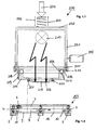
- the Figures 1.1 and 1.2 show in a sectional side view of a hand welder 200, which is intended for use with a positioning device 203.
- the hand welding device 200 according to the invention consists of a housing 201, which is shown as a one-piece variant. However, it is possible to manufacture the housing from several individual components. Above the housing 201, the possibility of a force introduction is shown by an arrow 204, which is exerted directly on a guided in a spring guide 206 spring 207. At the other end, the spring 207 rests on the upper housing cover 202, so that the force on the spring and the housing 201 is finally transferred to a An horrblende 215.
- the housing 201 can hereby be supported by a handle 205 additionally supportive.
- the introduced force serves to exert a pressure on the materials to be welded, namely until after the plasticization and cooling has hardened the joining zone has occurred.
- the spring 207 in this case it is possible to absorb pressure fluctuations in order to ensure a uniform pressure force by the Anticianblende 215.
- a radiation source 210 is arranged, which is symbolized by the two lightning arrows, the outgoing electromagnetic radiation is introduced through an existing shadow mask of An horrblende 215 directly into the materials to be welded, preferably plastic materials.
- the housing 201 is designed to be open at the bottom and closed by a flange 208 so far.
- the flange 208 is connected with the aid of a spacer ring 211 and distributed distribution bolts 216 with the housing.
- the flange disc 208 has a circumferential trough-shaped recess 209, which is provided for receiving a filled with an incompressible liquid tube 217.
- the hose 217 is in this case between the flange 208 and a positioning ring 214, wherein a fastening by circumferentially distributed springs 218 with screw 219 adjustment takes place.
- the springs 218 are in this case connected to the screw 219 at one end and rest at the other end in a recess of the flange 208, so that a quasi-elastic connection between the flange 208 and the positioning ring 214 is present.
- the positioning ring 214 serves as a support for a An horrblende 215, which is screwed by means of screws 220 with the positioning ring 214.
- the Anticianblende 215 rests here with a first larger radial portion in a recess 221 of the positioning ring 214 and is held by the screws 220.
- the pressure diaphragm 215 has, for example, segment-shaped openings 222, through which the electromagnetic radiation passes directly onto the plastic materials to be welded.
- a positioning device 203 which consists of a positioning ring 3 with a plurality of circumferentially distributed feet 4 and suction feet 5 located thereon.
- the suction feet 5 come here to lie directly on the plastic materials to be welded and allow a fixation of the positioning device 203 on the plastic materials.
- a vacuum device which is not shown, the air is sucked out of the suction feet 5 via a vacuum connection 6, so that the positioning device 203 can be fixed on the plastic.
- a Clothingsetzring 9 which is connected via webs 10 with the positioning ring 3, preferably in one piece. Between the webs 10 in this case a plurality of circumferentially distributed recesses 8 are formed.
- the attachment ring 9 has a bore 18 which is dimensioned in size so that the pressure plate 215 can be used. Through the bore 18 thus comes with a placement of the welder 200 on the fixed positioning 203, the pressure plate 215 to lie directly on the plastic materials.
- the particular advantage of this first embodiment is that with the help of the positioning device 203, first a fixation at the position to be welded of the plastic materials can be made, then the hand welding device 200 can be placed on the positioning device 203 with the help of the existing guide, wherein in Furthermore, it is ensured by the hose 217 filled with incompressible fluid that a uniform contact pressure is applied to the plastic material via the pressure diaphragm 215. In the event that the manual welder 200 should not be placed at right angles to the plastic material to be welded, thus a pressure equalization takes place and it is always ensured that a uniform contact pressure is present.
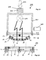
- the Figures 2.1 and 2.2 show a second embodiment of a manual welding device 300 with a housing 301 and a spring arranged above the housing 302, which is accommodated in a spring guide 306. Also on this spring 302 a force is exerted in the direction of arrow 304 to exert on the housing 301 and the existing Antikblende 16 a contact pressure on the materials to be welded.
- a radiation source 310 is arranged for electromagnetic radiation, which symbolized by the lightning arrows through the Antikblende 16 and the segment-shaped openings existing there can act directly on the plastic materials.
- the housing 301 has a handle 305, wherein the housing 301 is designed to be open at the bottom.
- the opening of the housing 301 is first closed by a spacer 311 and thereafter by a flange 14, wherein a screw connection by means of bolts 316 takes place.
- the flange 14 is part of a guide device 26, which in the further in the FIG. 1 known positioning device 203 can be used.
- the guide device 26 consists first of the bolted to the housing 301 flange 14, another flange 12 and a flange 7. Between the first and second flange 14, 12, a bearing element 11 is arranged, in each case in pairs, while between the second and third flange 7, 12, a second bearing element 13, also in pairs, is arranged.
- the two bearing elements 11, 13 are each arranged rotated by 90 ° to each other, so that a pivoting movement of the guide device 26 is given.
- the housing 301 can be used in case of need at an angle ⁇ 90 ° degrees with respect to the plastic plane to be processed.
- the guide device 26 in this case allows a pivoting movement of the housing 301 relative to the positioning device
- the positioning device 203 corresponds in an identical form of FIG. 1 known embodiment, wherein the pressure plate 16 is inserted into the bore 18.
- slippage of the manual welding device 300 can be excluded on the materials to be welded, wherein in addition by the pivoting mobility high flexibility with respect to a working angle.
- a uniform pressure force can thus be transmitted to the pressure diaphragm 16 and thus to the plastic material via the guide device 26.
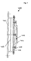
- FIG. 3 shows a perspective view of a first part of the positioning device 203, consisting of a first flange 14 for mounting on the welder, a second flange 12 and a third flange 7 as a guide ring.
- the flange 7 is used inter alia to attach the An horrblende 16, which is bolted via a mounting ring 15 with the flange 7.
- the individual flange discs 7, 12, 14 are connected to one another via bearing elements 11, 13, in such a way that in each case two paired bearing elements 11, 13 form a common axis and the bearing elements 11, 13 forming an axis between the first and second Flange 12, 14 and the second and third flange 7, 14 in this case are arranged offset by 90 ° to each other.
- the bearing elements 11, 13 themselves consist of a bearing bush 20 with a bearing journal 21, which has a cotter pin 22 and an enlarged collar 23 in the bearing bush 20 is attached. Furthermore, it can be seen from this view that the pressure diaphragm 16 has segment-like openings 24, through which the electromagnetic radiation passes into the absorbent layers of the lining material and / or the fastening and fixing points. Alternatively, there is the possibility that a glass pane transparent to electromagnetic radiation is used as a pressure diaphragm 16.
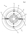
- FIG. 4 shows in a plan view of FIG. 3 known positioning device 203 with the flange 7, 12, 14 and the bearing elements 11, 13. From this view it can be seen that the pressure plate 16 is provided with segment-shaped openings 24, through which the electromagnetic radiation reaches the lining material.
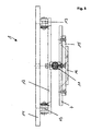
- FIG. 5 shows in a first side view of the positioning device 203 according to FIG. 3 , wherein from this view, the stepwise construction of the positioning device 203 can be seen, with an upper flange 14, which is intended for mounting to the welder and a central flange 12 and a lower flange 7. From this view, it is particularly clear that the upper and middle flange 12, 14 are connected to each other via the bearing elements 13, while the middle and lower flange 12, 7 are connected to each other via bearing elements 11.
- the offset by 90 ° position of the bearing elements 11, 13 in this case allows pivoting in all conceivable Aufsetzraumen the hand welder, so that a uniform contact pressure can be achieved in a false attached hand welding equipment.
- the Anyakblende 16 is in this case directly on the pressure surface 25 on the lining material. So that the pressure to be applied is transmitted by the hand welder alone through the Antikblende 16 is, as in particular from FIG. 1 can be seen, the positioning ring 7 is guided in the pocket-shaped recess 8, which allows regardless of the height of the positioning ring 3, a direct pressing the Antikblende 16 on the lining material. Only the exact position above the mounting and fixing point is determined by the positioning ring 3, whereby the exact position can be checked and corrected at any time by a visual inspection.
- the electromagnetic radiation source After placing the hand welder 2, the electromagnetic radiation source must be turned on for a short time until plasticization has taken place, and then the contact pressure is applied until the partially plasticized lining materials or fastening and fixing points have hardened to the extent that there is a permanent connection.
- FIG. 6 shows in a further side view of the positioning device 203 according to the structure of the preceding figures, in particular the FIG. 5 . From this representation, which compared to the FIG. 5 executed offset by 90 °, the connection of the middle and lower flange 12, 7 on the bearing elements 13 can be seen.
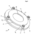
- FIG. 7 shows in a perspective view of the positioning device 203, namely a positioning ring 3, which is placed directly on the plastic materials to be welded by means of feet 4, which have on the head side suction cups 5, wherein via a vacuum connection 6, a negative pressure in the Saug Val 7 5 are generated can.
- the individual feet 4 are connected via a ring line, not shown, with the vacuum connection 6.
- the positioning device 203 here consists of a positioning ring 3 and a Aufsetzring 9 with a bore 18, which is further provided for receiving the An horrblende. Via webs 10, which are integrally formed integrally on the positioning ring 3, there is a connection with the Aufsetzring 9.
- the formed webs is formed between each two adjacent webs 10, a recess 8, which allows Aufsetzkontrolle the manual welding device.
- the length of the webs 10 was in this case chosen so that the hand welder with Anvikblende 16 can be used exactly in the positioning ring 3 and after putting on the welder the An réelleblende 16 comes to rest directly on the plastic material.
- the welding process itself is carried out with the aid of electromagnetic radiation, wherein the hand welding device 2 in various forms, depending on the type of electromagnetic radiation, can be constructed. With the help of the positioning device 203 All hand welders 2 can be used regardless of the type of electromagnetic radiation.
- FIG. 8 shows in a sectional side view of a further guide device 400, which can be used for example with the manual welder 300.
- the guide device 400 has a first flange 401, which is provided for screwing to the hand welding device, not shown. Between the flange 401 and another flange 402, an elastic body 403 is arranged, which, like the embodiment according to FIG. 2 allows a pivoting movement of the mounted hand welder to a small extent, while ensuring that the applied contact pressure is ensured evenly over the entire surface of the front Anvikblende 404.
- the An strigblende 404 is screwed with screws 405 to the flange 402 and has an outer dimension, which is formed corresponding to the bore 18 of the positioning device 203.
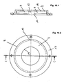
- FIGs 9.1 and 9.2 show in a plan view and a side view of the positioning device 203 with positioning ring 3, from which it can be seen that four suction cups 5 are arranged circumferentially distributed and via a ring channel 19 is a connection to the vacuum port 6.
- the annular channel 19 is formed in the positioning ring 3, which is used to receive the individual suction feet 5 and also serves to fasten the Aufsetzrings 9 via the webs 10.
- FIGS. 10.1 and 10.2 show in a plan view and a sectional side view of the step-shaped positioning ring 3 again in a single representation, from the cup-shaped training is visible. About the webs 10 in this case the positioning ring 3 is connected to the Aufsetzring 9, so that the pot-shaped configuration.
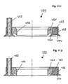
- This positioning device 450 consists of an annular disc 451 with a circumferential groove 452, in which a rubber ring 453 with V-shaped apart sealing lips 454 can be placed on the plastic material, not shown. Via a vacuum connection 455, the air can be sucked out below the rubber ring 453, so that the sealing lips 454 can be seeped to the plastic material.
- the upper part of the figure shows the positioning device 450 before the suction and the lower part figure after the suction with splayed sealing lips 454.
- this positioning device 450 also a definition of the hand welding devices 200 and 300 described can be done.
- the bore 456 can thus be placed centered on the plastic materials, the respective An horrblende the guide means, whereby the already described advantages arise that after determination of the positioning device 450 slipping of the hand welding device 200, 300 can be excluded.
Landscapes
- Engineering & Computer Science (AREA)
- Mechanical Engineering (AREA)
- Physics & Mathematics (AREA)
- Health & Medical Sciences (AREA)
- Electromagnetism (AREA)
- Toxicology (AREA)
- Lining Or Joining Of Plastics Or The Like (AREA)
Priority Applications (1)
| Application Number | Priority Date | Filing Date | Title |
|---|---|---|---|
| PL10732268T PL2435236T3 (pl) | 2009-05-29 | 2010-05-31 | Urządzenie pozycjonujące dla ręcznego aparatu spawalniczego |
Applications Claiming Priority (3)
| Application Number | Priority Date | Filing Date | Title |
|---|---|---|---|
| DE102009023219 | 2009-05-29 | ||
| DE102009053863A DE102009053863B4 (de) | 2009-05-29 | 2009-11-20 | Positioniereinrichtung für ein Handschweißgerät |
| PCT/DE2010/000589 WO2010136024A1 (de) | 2009-05-29 | 2010-05-31 | Positioniereinrichtung für ein handschweissgerät |
Publications (2)
| Publication Number | Publication Date |
|---|---|
| EP2435236A1 EP2435236A1 (de) | 2012-04-04 |
| EP2435236B1 true EP2435236B1 (de) | 2013-03-27 |
Family
ID=43049422
Family Applications (1)
| Application Number | Title | Priority Date | Filing Date |
|---|---|---|---|
| EP10732268A Active EP2435236B1 (de) | 2009-05-29 | 2010-05-31 | Positioniereinrichtung für ein handschweissgerät |
Country Status (6)
| Country | Link |
|---|---|
| US (1) | US9067365B2 (pl) |
| EP (1) | EP2435236B1 (pl) |
| CA (1) | CA2765432C (pl) |
| DE (1) | DE102009053863B4 (pl) |
| PL (1) | PL2435236T3 (pl) |
| WO (1) | WO2010136024A1 (pl) |
Families Citing this family (8)
| Publication number | Priority date | Publication date | Assignee | Title |
|---|---|---|---|---|
| DE102014212837B4 (de) | 2014-07-02 | 2023-08-17 | Robert Bosch Gmbh | Fügevorrichtung und Verfahren zum aneinander Fügen von toleranzbehafteten Werkstücken |
| CN109353713B (zh) * | 2018-12-07 | 2023-07-28 | 南通虹波机械有限公司 | 一种矿用泵站端部真空罐及其制作方法 |
| CN109760329B (zh) * | 2019-02-02 | 2024-02-20 | 台州市大地灯饰有限公司 | Led装饰灯带外表面亚克力颗粒裹覆装置 |
| CN111409270B (zh) * | 2020-04-08 | 2021-11-23 | 浙江安普森医疗器械有限公司 | 一种口罩耳带焊接装置 |
| CN115533351B (zh) * | 2022-10-20 | 2024-09-10 | 西安航天三沃机电设备有限责任公司 | 一种可拆卸的焊接压紧装置 |
| CN118926645B (zh) * | 2024-08-27 | 2025-01-24 | 山东华冠智能卡有限公司 | 一种用于石墨烯rfid天线芯片自动焊接装置 |
| CN120133822B (zh) * | 2025-05-13 | 2025-08-19 | 常州伟泰科技股份有限公司 | 半导体设备机架板附件防尘焊接装置 |
| CN121535439B (zh) * | 2026-01-19 | 2026-05-01 | 湖南福事特液压机械有限公司 | 用于油箱的焊接工装、变位机及焊接系统 |
Family Cites Families (5)
| Publication number | Priority date | Publication date | Assignee | Title |
|---|---|---|---|---|
| US6012711A (en) * | 1997-12-10 | 2000-01-11 | International Business Machines Corporation | Alignment device for establishing a coplanar relationship between first and second surfaces |
| US6083333A (en) | 1998-10-16 | 2000-07-04 | Itt Manufacturing Enterprises, Inc. | Self leveling weld fixture |
| DE102005058504B3 (de) * | 2005-12-02 | 2007-05-16 | Zeiss Ind Messtechnik Gmbh | Vorrichtung zum Bestimmen einer Messgröße an einem Messobjekt |
| WO2007090831A1 (en) * | 2006-02-07 | 2007-08-16 | Inergy Automotive Systems Research (Société Anonyme) | Process for manufacturing a fuel tank and tool for its implementation |
| DE102006035250B4 (de) | 2006-07-26 | 2011-02-24 | Jan Schmuck | Verbindungselement für einen Handschweißextruder |
-
2009
- 2009-11-20 DE DE102009053863A patent/DE102009053863B4/de active Active
-
2010
- 2010-05-31 PL PL10732268T patent/PL2435236T3/pl unknown
- 2010-05-31 CA CA2765432A patent/CA2765432C/en not_active Expired - Fee Related
- 2010-05-31 EP EP10732268A patent/EP2435236B1/de active Active
- 2010-05-31 US US13/322,759 patent/US9067365B2/en not_active Expired - Fee Related
- 2010-05-31 WO PCT/DE2010/000589 patent/WO2010136024A1/de not_active Ceased
Also Published As
| Publication number | Publication date |
|---|---|
| EP2435236A1 (de) | 2012-04-04 |
| DE102009053863A1 (de) | 2010-12-09 |
| WO2010136024A1 (de) | 2010-12-02 |
| CA2765432A1 (en) | 2010-12-02 |
| DE102009053863B4 (de) | 2013-11-21 |
| US20120132372A1 (en) | 2012-05-31 |
| US9067365B2 (en) | 2015-06-30 |
| PL2435236T3 (pl) | 2013-07-31 |
| CA2765432C (en) | 2016-09-20 |
Similar Documents
| Publication | Publication Date | Title |
|---|---|---|
| DE102009053863B4 (de) | Positioniereinrichtung für ein Handschweißgerät | |
| DE2337872C2 (de) | Gummi-Metall-Buchse | |
| DE102014013512A1 (de) | Membranventil | |
| EP3026006A1 (de) | Hubeinheit zum anheben und absenken eines behälters in einer behälterbehandlungsanlage | |
| DE2332123A1 (de) | Verfahren zur herstellung von verschlossenen und abgedichteten behaeltern und vorrichtung zur durchfuehrung dieses verfahrens | |
| EP3521029B1 (de) | Einstellungsmagnet für die herstellung von sicherheitselementen mit magnetisch orientierten effektpigmenten und herstellverfahren für solche einstellmagnete | |
| EP3807197A1 (de) | Mover für eine transportvorrichtung | |
| EP2268929B1 (de) | Haltevorrichtung für auskleidungsmaterialien | |
| EP3366554A1 (de) | Aufhängevorrichtung für transportgeräte | |
| EP2293922A2 (de) | Handschweissgerät | |
| EP0194501A2 (de) | Entnahmekopf für Flüssigkeitsbehälter | |
| EP3234422A1 (de) | Ventilvorrichtung in einem kraftfahrzeug und verfahren zur herstellung | |
| WO2009121346A2 (de) | Haltevorrichtung für auskleidungsmaterialien | |
| DE102007040179A1 (de) | Seitenteil für einen Rollladenkasten | |
| DE2134526C2 (de) | Verfahren und Vorrichtung zum Vorwarmen eines Reifenrohhngs | |
| EP4187133B1 (de) | Ventil | |
| WO2007042201A2 (de) | Kugelmühle mit zweipunktlagerung | |
| DE102013218002A1 (de) | Pipettiervorrichtung mit einer Kopplungsformation zur Ankopplung einer gesondert ausgebildeten Pipettierspitze und mit einem durch Magnetfeld formveränderbarem Verriegelungskörper zur Verriegelung und Entriegelung der Pipettierspitze an der Kopplungsformation | |
| EP2534071B1 (de) | Stutzenanordnung für eine innen liegende komponente | |
| CH713008A2 (de) | Verbindungssystem für Schlauchleitungen mit einer Hebelarmkupplung. | |
| DE102013103111A1 (de) | Halter für eine Behälteraufnahme und Behälteraufnahme | |
| DE202014010992U1 (de) | Tubenhalter für eine Tubenfüllmaschine | |
| DE202007004200U1 (de) | Variabler Spigot | |
| DE102022125839A1 (de) | Bauteilaufnahme zum Herstellen eines Kunststoffteils | |
| DE10053243C2 (de) | Verfahren und Vorrichtung zur Verfeinerung eines Pulvers |
Legal Events
| Date | Code | Title | Description |
|---|---|---|---|
| PUAI | Public reference made under article 153(3) epc to a published international application that has entered the european phase |
Free format text: ORIGINAL CODE: 0009012 |
|
| 17P | Request for examination filed |
Effective date: 20111228 |
|
| AK | Designated contracting states |
Kind code of ref document: A1 Designated state(s): AL AT BE BG CH CY CZ DE DK EE ES FI FR GB GR HR HU IE IS IT LI LT LU LV MC MK MT NL NO PL PT RO SE SI SK SM TR |
|
| DAX | Request for extension of the european patent (deleted) | ||
| GRAP | Despatch of communication of intention to grant a patent |
Free format text: ORIGINAL CODE: EPIDOSNIGR1 |
|
| GRAS | Grant fee paid |
Free format text: ORIGINAL CODE: EPIDOSNIGR3 |
|
| GRAA | (expected) grant |
Free format text: ORIGINAL CODE: 0009210 |
|
| AK | Designated contracting states |
Kind code of ref document: B1 Designated state(s): AL AT BE BG CH CY CZ DE DK EE ES FI FR GB GR HR HU IE IS IT LI LT LU LV MC MK MT NL NO PL PT RO SE SI SK SM TR |
|
| REG | Reference to a national code |
Ref country code: GB Ref legal event code: FG4D Free format text: NOT ENGLISH |
|
| REG | Reference to a national code |
Ref country code: CH Ref legal event code: EP |
|
| REG | Reference to a national code |
Ref country code: AT Ref legal event code: REF Ref document number: 603086 Country of ref document: AT Kind code of ref document: T Effective date: 20130415 |
|
| REG | Reference to a national code |
Ref country code: IE Ref legal event code: FG4D Free format text: LANGUAGE OF EP DOCUMENT: GERMAN |
|
| REG | Reference to a national code |
Ref country code: DE Ref legal event code: R096 Ref document number: 502010002731 Country of ref document: DE Effective date: 20130529 |
|
| PG25 | Lapsed in a contracting state [announced via postgrant information from national office to epo] |
Ref country code: BG Free format text: LAPSE BECAUSE OF FAILURE TO SUBMIT A TRANSLATION OF THE DESCRIPTION OR TO PAY THE FEE WITHIN THE PRESCRIBED TIME-LIMIT Effective date: 20130627 Ref country code: LT Free format text: LAPSE BECAUSE OF FAILURE TO SUBMIT A TRANSLATION OF THE DESCRIPTION OR TO PAY THE FEE WITHIN THE PRESCRIBED TIME-LIMIT Effective date: 20130327 Ref country code: NO Free format text: LAPSE BECAUSE OF FAILURE TO SUBMIT A TRANSLATION OF THE DESCRIPTION OR TO PAY THE FEE WITHIN THE PRESCRIBED TIME-LIMIT Effective date: 20130627 Ref country code: SE Free format text: LAPSE BECAUSE OF FAILURE TO SUBMIT A TRANSLATION OF THE DESCRIPTION OR TO PAY THE FEE WITHIN THE PRESCRIBED TIME-LIMIT Effective date: 20130327 |
|
| REG | Reference to a national code |
Ref country code: PL Ref legal event code: T3 |
|
| REG | Reference to a national code |
Ref country code: NL Ref legal event code: T3 |
|
| REG | Reference to a national code |
Ref country code: LT Ref legal event code: MG4D |
|
| PG25 | Lapsed in a contracting state [announced via postgrant information from national office to epo] |
Ref country code: FI Free format text: LAPSE BECAUSE OF FAILURE TO SUBMIT A TRANSLATION OF THE DESCRIPTION OR TO PAY THE FEE WITHIN THE PRESCRIBED TIME-LIMIT Effective date: 20130327 Ref country code: GR Free format text: LAPSE BECAUSE OF FAILURE TO SUBMIT A TRANSLATION OF THE DESCRIPTION OR TO PAY THE FEE WITHIN THE PRESCRIBED TIME-LIMIT Effective date: 20130628 Ref country code: LV Free format text: LAPSE BECAUSE OF FAILURE TO SUBMIT A TRANSLATION OF THE DESCRIPTION OR TO PAY THE FEE WITHIN THE PRESCRIBED TIME-LIMIT Effective date: 20130327 Ref country code: SI Free format text: LAPSE BECAUSE OF FAILURE TO SUBMIT A TRANSLATION OF THE DESCRIPTION OR TO PAY THE FEE WITHIN THE PRESCRIBED TIME-LIMIT Effective date: 20130327 |
|
| PG25 | Lapsed in a contracting state [announced via postgrant information from national office to epo] |
Ref country code: HR Free format text: LAPSE BECAUSE OF FAILURE TO SUBMIT A TRANSLATION OF THE DESCRIPTION OR TO PAY THE FEE WITHIN THE PRESCRIBED TIME-LIMIT Effective date: 20130327 |
|
| PG25 | Lapsed in a contracting state [announced via postgrant information from national office to epo] |
Ref country code: RO Free format text: LAPSE BECAUSE OF FAILURE TO SUBMIT A TRANSLATION OF THE DESCRIPTION OR TO PAY THE FEE WITHIN THE PRESCRIBED TIME-LIMIT Effective date: 20130327 Ref country code: EE Free format text: LAPSE BECAUSE OF FAILURE TO SUBMIT A TRANSLATION OF THE DESCRIPTION OR TO PAY THE FEE WITHIN THE PRESCRIBED TIME-LIMIT Effective date: 20130327 Ref country code: PT Free format text: LAPSE BECAUSE OF FAILURE TO SUBMIT A TRANSLATION OF THE DESCRIPTION OR TO PAY THE FEE WITHIN THE PRESCRIBED TIME-LIMIT Effective date: 20130729 Ref country code: IS Free format text: LAPSE BECAUSE OF FAILURE TO SUBMIT A TRANSLATION OF THE DESCRIPTION OR TO PAY THE FEE WITHIN THE PRESCRIBED TIME-LIMIT Effective date: 20130727 Ref country code: ES Free format text: LAPSE BECAUSE OF FAILURE TO SUBMIT A TRANSLATION OF THE DESCRIPTION OR TO PAY THE FEE WITHIN THE PRESCRIBED TIME-LIMIT Effective date: 20130708 Ref country code: SK Free format text: LAPSE BECAUSE OF FAILURE TO SUBMIT A TRANSLATION OF THE DESCRIPTION OR TO PAY THE FEE WITHIN THE PRESCRIBED TIME-LIMIT Effective date: 20130327 Ref country code: CZ Free format text: LAPSE BECAUSE OF FAILURE TO SUBMIT A TRANSLATION OF THE DESCRIPTION OR TO PAY THE FEE WITHIN THE PRESCRIBED TIME-LIMIT Effective date: 20130327 |
|
| PG25 | Lapsed in a contracting state [announced via postgrant information from national office to epo] |
Ref country code: CY Free format text: LAPSE BECAUSE OF FAILURE TO SUBMIT A TRANSLATION OF THE DESCRIPTION OR TO PAY THE FEE WITHIN THE PRESCRIBED TIME-LIMIT Effective date: 20130327 |
|
| PG25 | Lapsed in a contracting state [announced via postgrant information from national office to epo] |
Ref country code: MC Free format text: LAPSE BECAUSE OF FAILURE TO SUBMIT A TRANSLATION OF THE DESCRIPTION OR TO PAY THE FEE WITHIN THE PRESCRIBED TIME-LIMIT Effective date: 20130327 |
|
| PG25 | Lapsed in a contracting state [announced via postgrant information from national office to epo] |
Ref country code: DK Free format text: LAPSE BECAUSE OF FAILURE TO SUBMIT A TRANSLATION OF THE DESCRIPTION OR TO PAY THE FEE WITHIN THE PRESCRIBED TIME-LIMIT Effective date: 20130327 |
|
| PLBE | No opposition filed within time limit |
Free format text: ORIGINAL CODE: 0009261 |
|
| STAA | Information on the status of an ep patent application or granted ep patent |
Free format text: STATUS: NO OPPOSITION FILED WITHIN TIME LIMIT |
|
| PG25 | Lapsed in a contracting state [announced via postgrant information from national office to epo] |
Ref country code: IT Free format text: LAPSE BECAUSE OF FAILURE TO SUBMIT A TRANSLATION OF THE DESCRIPTION OR TO PAY THE FEE WITHIN THE PRESCRIBED TIME-LIMIT Effective date: 20130327 |
|
| 26N | No opposition filed |
Effective date: 20140103 |
|
| REG | Reference to a national code |
Ref country code: DE Ref legal event code: R097 Ref document number: 502010002731 Country of ref document: DE Effective date: 20140103 |
|
| PG25 | Lapsed in a contracting state [announced via postgrant information from national office to epo] |
Ref country code: MT Free format text: LAPSE BECAUSE OF FAILURE TO SUBMIT A TRANSLATION OF THE DESCRIPTION OR TO PAY THE FEE WITHIN THE PRESCRIBED TIME-LIMIT Effective date: 20130327 |
|
| PG25 | Lapsed in a contracting state [announced via postgrant information from national office to epo] |
Ref country code: SM Free format text: LAPSE BECAUSE OF FAILURE TO SUBMIT A TRANSLATION OF THE DESCRIPTION OR TO PAY THE FEE WITHIN THE PRESCRIBED TIME-LIMIT Effective date: 20130327 |
|
| PG25 | Lapsed in a contracting state [announced via postgrant information from national office to epo] |
Ref country code: TR Free format text: LAPSE BECAUSE OF FAILURE TO SUBMIT A TRANSLATION OF THE DESCRIPTION OR TO PAY THE FEE WITHIN THE PRESCRIBED TIME-LIMIT Effective date: 20130327 |
|
| PG25 | Lapsed in a contracting state [announced via postgrant information from national office to epo] |
Ref country code: MK Free format text: LAPSE BECAUSE OF FAILURE TO SUBMIT A TRANSLATION OF THE DESCRIPTION OR TO PAY THE FEE WITHIN THE PRESCRIBED TIME-LIMIT Effective date: 20130327 Ref country code: HU Free format text: LAPSE BECAUSE OF FAILURE TO SUBMIT A TRANSLATION OF THE DESCRIPTION OR TO PAY THE FEE WITHIN THE PRESCRIBED TIME-LIMIT; INVALID AB INITIO Effective date: 20100531 |
|
| REG | Reference to a national code |
Ref country code: FR Ref legal event code: PLFP Year of fee payment: 7 |
|
| REG | Reference to a national code |
Ref country code: FR Ref legal event code: PLFP Year of fee payment: 8 |
|
| PGFP | Annual fee paid to national office [announced via postgrant information from national office to epo] |
Ref country code: IE Payment date: 20170523 Year of fee payment: 8 Ref country code: FR Payment date: 20170522 Year of fee payment: 8 Ref country code: GB Payment date: 20170524 Year of fee payment: 8 |
|
| PGFP | Annual fee paid to national office [announced via postgrant information from national office to epo] |
Ref country code: LU Payment date: 20170522 Year of fee payment: 8 |
|
| PG25 | Lapsed in a contracting state [announced via postgrant information from national office to epo] |
Ref country code: AL Free format text: LAPSE BECAUSE OF FAILURE TO SUBMIT A TRANSLATION OF THE DESCRIPTION OR TO PAY THE FEE WITHIN THE PRESCRIBED TIME-LIMIT Effective date: 20130327 |
|
| GBPC | Gb: european patent ceased through non-payment of renewal fee |
Effective date: 20180531 |
|
| REG | Reference to a national code |
Ref country code: IE Ref legal event code: MM4A |
|
| PG25 | Lapsed in a contracting state [announced via postgrant information from national office to epo] |
Ref country code: LU Free format text: LAPSE BECAUSE OF NON-PAYMENT OF DUE FEES Effective date: 20180531 |
|
| PG25 | Lapsed in a contracting state [announced via postgrant information from national office to epo] |
Ref country code: FR Free format text: LAPSE BECAUSE OF NON-PAYMENT OF DUE FEES Effective date: 20180531 Ref country code: GB Free format text: LAPSE BECAUSE OF NON-PAYMENT OF DUE FEES Effective date: 20180531 Ref country code: IE Free format text: LAPSE BECAUSE OF NON-PAYMENT OF DUE FEES Effective date: 20180531 |
|
| P01 | Opt-out of the competence of the unified patent court (upc) registered |
Effective date: 20230601 |
|
| REG | Reference to a national code |
Ref country code: DE Ref legal event code: R082 Ref document number: 502010002731 Country of ref document: DE Representative=s name: SEYER & NOBBE PATENTANWAELTE PARTNERSCHAFTSGES, DE |
|
| PGFP | Annual fee paid to national office [announced via postgrant information from national office to epo] |
Ref country code: NL Payment date: 20240522 Year of fee payment: 15 |
|
| PGFP | Annual fee paid to national office [announced via postgrant information from national office to epo] |
Ref country code: DE Payment date: 20240506 Year of fee payment: 15 |
|
| PGFP | Annual fee paid to national office [announced via postgrant information from national office to epo] |
Ref country code: CH Payment date: 20240602 Year of fee payment: 15 |
|
| PGFP | Annual fee paid to national office [announced via postgrant information from national office to epo] |
Ref country code: AT Payment date: 20240517 Year of fee payment: 15 |
|
| PGFP | Annual fee paid to national office [announced via postgrant information from national office to epo] |
Ref country code: PL Payment date: 20240506 Year of fee payment: 15 |
|
| PGFP | Annual fee paid to national office [announced via postgrant information from national office to epo] |
Ref country code: BE Payment date: 20240521 Year of fee payment: 15 |
|
| REG | Reference to a national code |
Ref country code: DE Ref legal event code: R119 Ref document number: 502010002731 Country of ref document: DE |
|
| REG | Reference to a national code |
Ref country code: CH Ref legal event code: H13 Free format text: ST27 STATUS EVENT CODE: U-0-0-H10-H13 (AS PROVIDED BY THE NATIONAL OFFICE) Effective date: 20251223 |
|
| REG | Reference to a national code |
Ref country code: NL Ref legal event code: MM Effective date: 20250601 |
|
| PG25 | Lapsed in a contracting state [announced via postgrant information from national office to epo] |
Ref country code: AT Free format text: LAPSE BECAUSE OF NON-PAYMENT OF DUE FEES Effective date: 20250531 |
|
| REG | Reference to a national code |
Ref country code: AT Ref legal event code: MM01 Ref document number: 603086 Country of ref document: AT Kind code of ref document: T Effective date: 20250531 |
|
| PG25 | Lapsed in a contracting state [announced via postgrant information from national office to epo] |
Ref country code: CH Free format text: LAPSE BECAUSE OF NON-PAYMENT OF DUE FEES Effective date: 20250531 |
|
| REG | Reference to a national code |
Ref country code: BE Ref legal event code: MM Effective date: 20250531 |
|
| PG25 | Lapsed in a contracting state [announced via postgrant information from national office to epo] |
Ref country code: NL Free format text: LAPSE BECAUSE OF NON-PAYMENT OF DUE FEES Effective date: 20250601 |
|
| PG25 | Lapsed in a contracting state [announced via postgrant information from national office to epo] |
Ref country code: DE Free format text: LAPSE BECAUSE OF NON-PAYMENT OF DUE FEES Effective date: 20251202 |
|
| PG25 | Lapsed in a contracting state [announced via postgrant information from national office to epo] |
Ref country code: BE Free format text: LAPSE BECAUSE OF NON-PAYMENT OF DUE FEES Effective date: 20250531 |