EP2435236B1 - Positioniereinrichtung für ein handschweissgerät - Google Patents
Positioniereinrichtung für ein handschweissgerät Download PDFInfo
- Publication number
- EP2435236B1 EP2435236B1 EP10732268A EP10732268A EP2435236B1 EP 2435236 B1 EP2435236 B1 EP 2435236B1 EP 10732268 A EP10732268 A EP 10732268A EP 10732268 A EP10732268 A EP 10732268A EP 2435236 B1 EP2435236 B1 EP 2435236B1
- Authority
- EP
- European Patent Office
- Prior art keywords
- positioning device
- positioning
- pressure screen
- ring
- flange
- Prior art date
- Legal status (The legal status is an assumption and is not a legal conclusion. Google has not performed a legal analysis and makes no representation as to the accuracy of the status listed.)
- Active
Links
Images



Classifications
-
- B—PERFORMING OPERATIONS; TRANSPORTING
- B29—WORKING OF PLASTICS; WORKING OF SUBSTANCES IN A PLASTIC STATE IN GENERAL
- B29C—SHAPING OR JOINING OF PLASTICS; SHAPING OF MATERIAL IN A PLASTIC STATE, NOT OTHERWISE PROVIDED FOR; AFTER-TREATMENT OF THE SHAPED PRODUCTS, e.g. REPAIRING
- B29C66/00—General aspects of processes or apparatus for joining preformed parts
- B29C66/80—General aspects of machine operations or constructions and parts thereof
- B29C66/84—Specific machine types or machines suitable for specific applications
- B29C66/861—Hand-held tools
-
- B—PERFORMING OPERATIONS; TRANSPORTING
- B29—WORKING OF PLASTICS; WORKING OF SUBSTANCES IN A PLASTIC STATE IN GENERAL
- B29C—SHAPING OR JOINING OF PLASTICS; SHAPING OF MATERIAL IN A PLASTIC STATE, NOT OTHERWISE PROVIDED FOR; AFTER-TREATMENT OF THE SHAPED PRODUCTS, e.g. REPAIRING
- B29C65/00—Joining or sealing of preformed parts, e.g. welding of plastics materials; Apparatus therefor
- B29C65/02—Joining or sealing of preformed parts, e.g. welding of plastics materials; Apparatus therefor by heating, with or without pressure
- B29C65/14—Joining or sealing of preformed parts, e.g. welding of plastics materials; Apparatus therefor by heating, with or without pressure using wave energy, i.e. electromagnetic radiation, or particle radiation
- B29C65/1496—Joining or sealing of preformed parts, e.g. welding of plastics materials; Apparatus therefor by heating, with or without pressure using wave energy, i.e. electromagnetic radiation, or particle radiation making use of masks
-
- B—PERFORMING OPERATIONS; TRANSPORTING
- B29—WORKING OF PLASTICS; WORKING OF SUBSTANCES IN A PLASTIC STATE IN GENERAL
- B29C—SHAPING OR JOINING OF PLASTICS; SHAPING OF MATERIAL IN A PLASTIC STATE, NOT OTHERWISE PROVIDED FOR; AFTER-TREATMENT OF THE SHAPED PRODUCTS, e.g. REPAIRING
- B29C65/00—Joining or sealing of preformed parts, e.g. welding of plastics materials; Apparatus therefor
- B29C65/78—Means for handling the parts to be joined, e.g. for making containers or hollow articles, e.g. means for handling sheets, plates, web-like materials, tubular articles, hollow articles or elements to be joined therewith; Means for discharging the joined articles from the joining apparatus
- B29C65/7841—Holding or clamping means for handling purposes
- B29C65/7847—Holding or clamping means for handling purposes using vacuum to hold at least one of the parts to be joined
-
- B—PERFORMING OPERATIONS; TRANSPORTING
- B29—WORKING OF PLASTICS; WORKING OF SUBSTANCES IN A PLASTIC STATE IN GENERAL
- B29C—SHAPING OR JOINING OF PLASTICS; SHAPING OF MATERIAL IN A PLASTIC STATE, NOT OTHERWISE PROVIDED FOR; AFTER-TREATMENT OF THE SHAPED PRODUCTS, e.g. REPAIRING
- B29C66/00—General aspects of processes or apparatus for joining preformed parts
- B29C66/80—General aspects of machine operations or constructions and parts thereof
- B29C66/81—General aspects of the pressing elements, i.e. the elements applying pressure on the parts to be joined in the area to be joined, e.g. the welding jaws or clamps
- B29C66/816—General aspects of the pressing elements, i.e. the elements applying pressure on the parts to be joined in the area to be joined, e.g. the welding jaws or clamps characterised by the mounting of the pressing elements, e.g. of the welding jaws or clamps
- B29C66/8161—General aspects of the pressing elements, i.e. the elements applying pressure on the parts to be joined in the area to be joined, e.g. the welding jaws or clamps characterised by the mounting of the pressing elements, e.g. of the welding jaws or clamps said pressing elements being supported or backed-up by springs or by resilient material
-
- B—PERFORMING OPERATIONS; TRANSPORTING
- B29—WORKING OF PLASTICS; WORKING OF SUBSTANCES IN A PLASTIC STATE IN GENERAL
- B29C—SHAPING OR JOINING OF PLASTICS; SHAPING OF MATERIAL IN A PLASTIC STATE, NOT OTHERWISE PROVIDED FOR; AFTER-TREATMENT OF THE SHAPED PRODUCTS, e.g. REPAIRING
- B29C66/00—General aspects of processes or apparatus for joining preformed parts
- B29C66/80—General aspects of machine operations or constructions and parts thereof
- B29C66/81—General aspects of the pressing elements, i.e. the elements applying pressure on the parts to be joined in the area to be joined, e.g. the welding jaws or clamps
- B29C66/816—General aspects of the pressing elements, i.e. the elements applying pressure on the parts to be joined in the area to be joined, e.g. the welding jaws or clamps characterised by the mounting of the pressing elements, e.g. of the welding jaws or clamps
- B29C66/8163—Self-aligning to the joining plane, e.g. mounted on a ball and socket
-
- B—PERFORMING OPERATIONS; TRANSPORTING
- B29—WORKING OF PLASTICS; WORKING OF SUBSTANCES IN A PLASTIC STATE IN GENERAL
- B29C—SHAPING OR JOINING OF PLASTICS; SHAPING OF MATERIAL IN A PLASTIC STATE, NOT OTHERWISE PROVIDED FOR; AFTER-TREATMENT OF THE SHAPED PRODUCTS, e.g. REPAIRING
- B29C66/00—General aspects of processes or apparatus for joining preformed parts
- B29C66/80—General aspects of machine operations or constructions and parts thereof
- B29C66/83—General aspects of machine operations or constructions and parts thereof characterised by the movement of the joining or pressing tools
- B29C66/832—Reciprocating joining or pressing tools
- B29C66/8322—Joining or pressing tools reciprocating along one axis
-
- B—PERFORMING OPERATIONS; TRANSPORTING
- B29—WORKING OF PLASTICS; WORKING OF SUBSTANCES IN A PLASTIC STATE IN GENERAL
- B29C—SHAPING OR JOINING OF PLASTICS; SHAPING OF MATERIAL IN A PLASTIC STATE, NOT OTHERWISE PROVIDED FOR; AFTER-TREATMENT OF THE SHAPED PRODUCTS, e.g. REPAIRING
- B29C65/00—Joining or sealing of preformed parts, e.g. welding of plastics materials; Apparatus therefor
- B29C65/02—Joining or sealing of preformed parts, e.g. welding of plastics materials; Apparatus therefor by heating, with or without pressure
- B29C65/14—Joining or sealing of preformed parts, e.g. welding of plastics materials; Apparatus therefor by heating, with or without pressure using wave energy, i.e. electromagnetic radiation, or particle radiation
- B29C65/1403—Joining or sealing of preformed parts, e.g. welding of plastics materials; Apparatus therefor by heating, with or without pressure using wave energy, i.e. electromagnetic radiation, or particle radiation characterised by the type of electromagnetic or particle radiation
- B29C65/1412—Infrared [IR] radiation
-
- B—PERFORMING OPERATIONS; TRANSPORTING
- B29—WORKING OF PLASTICS; WORKING OF SUBSTANCES IN A PLASTIC STATE IN GENERAL
- B29C—SHAPING OR JOINING OF PLASTICS; SHAPING OF MATERIAL IN A PLASTIC STATE, NOT OTHERWISE PROVIDED FOR; AFTER-TREATMENT OF THE SHAPED PRODUCTS, e.g. REPAIRING
- B29C65/00—Joining or sealing of preformed parts, e.g. welding of plastics materials; Apparatus therefor
- B29C65/02—Joining or sealing of preformed parts, e.g. welding of plastics materials; Apparatus therefor by heating, with or without pressure
- B29C65/14—Joining or sealing of preformed parts, e.g. welding of plastics materials; Apparatus therefor by heating, with or without pressure using wave energy, i.e. electromagnetic radiation, or particle radiation
- B29C65/1403—Joining or sealing of preformed parts, e.g. welding of plastics materials; Apparatus therefor by heating, with or without pressure using wave energy, i.e. electromagnetic radiation, or particle radiation characterised by the type of electromagnetic or particle radiation
- B29C65/1425—Microwave radiation
-
- B—PERFORMING OPERATIONS; TRANSPORTING
- B29—WORKING OF PLASTICS; WORKING OF SUBSTANCES IN A PLASTIC STATE IN GENERAL
- B29C—SHAPING OR JOINING OF PLASTICS; SHAPING OF MATERIAL IN A PLASTIC STATE, NOT OTHERWISE PROVIDED FOR; AFTER-TREATMENT OF THE SHAPED PRODUCTS, e.g. REPAIRING
- B29C65/00—Joining or sealing of preformed parts, e.g. welding of plastics materials; Apparatus therefor
- B29C65/02—Joining or sealing of preformed parts, e.g. welding of plastics materials; Apparatus therefor by heating, with or without pressure
- B29C65/14—Joining or sealing of preformed parts, e.g. welding of plastics materials; Apparatus therefor by heating, with or without pressure using wave energy, i.e. electromagnetic radiation, or particle radiation
- B29C65/1429—Joining or sealing of preformed parts, e.g. welding of plastics materials; Apparatus therefor by heating, with or without pressure using wave energy, i.e. electromagnetic radiation, or particle radiation characterised by the way of heating the interface
- B29C65/1435—Joining or sealing of preformed parts, e.g. welding of plastics materials; Apparatus therefor by heating, with or without pressure using wave energy, i.e. electromagnetic radiation, or particle radiation characterised by the way of heating the interface at least passing through one of the parts to be joined, i.e. transmission welding
- B29C65/1438—Joining or sealing of preformed parts, e.g. welding of plastics materials; Apparatus therefor by heating, with or without pressure using wave energy, i.e. electromagnetic radiation, or particle radiation characterised by the way of heating the interface at least passing through one of the parts to be joined, i.e. transmission welding focusing the wave energy or particle radiation on the interface
-
- B—PERFORMING OPERATIONS; TRANSPORTING
- B29—WORKING OF PLASTICS; WORKING OF SUBSTANCES IN A PLASTIC STATE IN GENERAL
- B29C—SHAPING OR JOINING OF PLASTICS; SHAPING OF MATERIAL IN A PLASTIC STATE, NOT OTHERWISE PROVIDED FOR; AFTER-TREATMENT OF THE SHAPED PRODUCTS, e.g. REPAIRING
- B29C65/00—Joining or sealing of preformed parts, e.g. welding of plastics materials; Apparatus therefor
- B29C65/02—Joining or sealing of preformed parts, e.g. welding of plastics materials; Apparatus therefor by heating, with or without pressure
- B29C65/14—Joining or sealing of preformed parts, e.g. welding of plastics materials; Apparatus therefor by heating, with or without pressure using wave energy, i.e. electromagnetic radiation, or particle radiation
- B29C65/1477—Joining or sealing of preformed parts, e.g. welding of plastics materials; Apparatus therefor by heating, with or without pressure using wave energy, i.e. electromagnetic radiation, or particle radiation making use of an absorber or impact modifier
- B29C65/1483—Joining or sealing of preformed parts, e.g. welding of plastics materials; Apparatus therefor by heating, with or without pressure using wave energy, i.e. electromagnetic radiation, or particle radiation making use of an absorber or impact modifier coated on the article
-
- B—PERFORMING OPERATIONS; TRANSPORTING
- B29—WORKING OF PLASTICS; WORKING OF SUBSTANCES IN A PLASTIC STATE IN GENERAL
- B29C—SHAPING OR JOINING OF PLASTICS; SHAPING OF MATERIAL IN A PLASTIC STATE, NOT OTHERWISE PROVIDED FOR; AFTER-TREATMENT OF THE SHAPED PRODUCTS, e.g. REPAIRING
- B29C65/00—Joining or sealing of preformed parts, e.g. welding of plastics materials; Apparatus therefor
- B29C65/02—Joining or sealing of preformed parts, e.g. welding of plastics materials; Apparatus therefor by heating, with or without pressure
- B29C65/14—Joining or sealing of preformed parts, e.g. welding of plastics materials; Apparatus therefor by heating, with or without pressure using wave energy, i.e. electromagnetic radiation, or particle radiation
- B29C65/16—Laser beams
- B29C65/1603—Laser beams characterised by the type of electromagnetic radiation
- B29C65/1612—Infrared [IR] radiation, e.g. by infrared lasers
- B29C65/1619—Mid infrared radiation [MIR], e.g. by CO or CO2 lasers
-
- B—PERFORMING OPERATIONS; TRANSPORTING
- B29—WORKING OF PLASTICS; WORKING OF SUBSTANCES IN A PLASTIC STATE IN GENERAL
- B29C—SHAPING OR JOINING OF PLASTICS; SHAPING OF MATERIAL IN A PLASTIC STATE, NOT OTHERWISE PROVIDED FOR; AFTER-TREATMENT OF THE SHAPED PRODUCTS, e.g. REPAIRING
- B29C65/00—Joining or sealing of preformed parts, e.g. welding of plastics materials; Apparatus therefor
- B29C65/02—Joining or sealing of preformed parts, e.g. welding of plastics materials; Apparatus therefor by heating, with or without pressure
- B29C65/14—Joining or sealing of preformed parts, e.g. welding of plastics materials; Apparatus therefor by heating, with or without pressure using wave energy, i.e. electromagnetic radiation, or particle radiation
- B29C65/16—Laser beams
- B29C65/1687—Laser beams making use of light guides
-
- B—PERFORMING OPERATIONS; TRANSPORTING
- B29—WORKING OF PLASTICS; WORKING OF SUBSTANCES IN A PLASTIC STATE IN GENERAL
- B29C—SHAPING OR JOINING OF PLASTICS; SHAPING OF MATERIAL IN A PLASTIC STATE, NOT OTHERWISE PROVIDED FOR; AFTER-TREATMENT OF THE SHAPED PRODUCTS, e.g. REPAIRING
- B29C65/00—Joining or sealing of preformed parts, e.g. welding of plastics materials; Apparatus therefor
- B29C65/02—Joining or sealing of preformed parts, e.g. welding of plastics materials; Apparatus therefor by heating, with or without pressure
- B29C65/14—Joining or sealing of preformed parts, e.g. welding of plastics materials; Apparatus therefor by heating, with or without pressure using wave energy, i.e. electromagnetic radiation, or particle radiation
- B29C65/16—Laser beams
- B29C65/1696—Laser beams making use of masks
-
- B—PERFORMING OPERATIONS; TRANSPORTING
- B29—WORKING OF PLASTICS; WORKING OF SUBSTANCES IN A PLASTIC STATE IN GENERAL
- B29C—SHAPING OR JOINING OF PLASTICS; SHAPING OF MATERIAL IN A PLASTIC STATE, NOT OTHERWISE PROVIDED FOR; AFTER-TREATMENT OF THE SHAPED PRODUCTS, e.g. REPAIRING
- B29C66/00—General aspects of processes or apparatus for joining preformed parts
- B29C66/70—General aspects of processes or apparatus for joining preformed parts characterised by the composition, physical properties or the structure of the material of the parts to be joined; Joining with non-plastics material
- B29C66/73—General aspects of processes or apparatus for joining preformed parts characterised by the composition, physical properties or the structure of the material of the parts to be joined; Joining with non-plastics material characterised by the intensive physical properties of the material of the parts to be joined, by the optical properties of the material of the parts to be joined, by the extensive physical properties of the parts to be joined, by the state of the material of the parts to be joined or by the material of the parts to be joined being a thermoplastic or a thermoset
- B29C66/739—General aspects of processes or apparatus for joining preformed parts characterised by the composition, physical properties or the structure of the material of the parts to be joined; Joining with non-plastics material characterised by the intensive physical properties of the material of the parts to be joined, by the optical properties of the material of the parts to be joined, by the extensive physical properties of the parts to be joined, by the state of the material of the parts to be joined or by the material of the parts to be joined being a thermoplastic or a thermoset characterised by the material of the parts to be joined being a thermoplastic or a thermoset
- B29C66/7392—General aspects of processes or apparatus for joining preformed parts characterised by the composition, physical properties or the structure of the material of the parts to be joined; Joining with non-plastics material characterised by the intensive physical properties of the material of the parts to be joined, by the optical properties of the material of the parts to be joined, by the extensive physical properties of the parts to be joined, by the state of the material of the parts to be joined or by the material of the parts to be joined being a thermoplastic or a thermoset characterised by the material of the parts to be joined being a thermoplastic or a thermoset characterised by the material of at least one of the parts being a thermoplastic
- B29C66/73921—General aspects of processes or apparatus for joining preformed parts characterised by the composition, physical properties or the structure of the material of the parts to be joined; Joining with non-plastics material characterised by the intensive physical properties of the material of the parts to be joined, by the optical properties of the material of the parts to be joined, by the extensive physical properties of the parts to be joined, by the state of the material of the parts to be joined or by the material of the parts to be joined being a thermoplastic or a thermoset characterised by the material of the parts to be joined being a thermoplastic or a thermoset characterised by the material of at least one of the parts being a thermoplastic characterised by the materials of both parts being thermoplastics
-
- B—PERFORMING OPERATIONS; TRANSPORTING
- B29—WORKING OF PLASTICS; WORKING OF SUBSTANCES IN A PLASTIC STATE IN GENERAL
- B29C—SHAPING OR JOINING OF PLASTICS; SHAPING OF MATERIAL IN A PLASTIC STATE, NOT OTHERWISE PROVIDED FOR; AFTER-TREATMENT OF THE SHAPED PRODUCTS, e.g. REPAIRING
- B29C66/00—General aspects of processes or apparatus for joining preformed parts
- B29C66/80—General aspects of machine operations or constructions and parts thereof
- B29C66/81—General aspects of the pressing elements, i.e. the elements applying pressure on the parts to be joined in the area to be joined, e.g. the welding jaws or clamps
- B29C66/812—General aspects of the pressing elements, i.e. the elements applying pressure on the parts to be joined in the area to be joined, e.g. the welding jaws or clamps characterised by the composition, by the structure, by the intensive physical properties or by the optical properties of the material constituting the pressing elements, e.g. constituting the welding jaws or clamps
- B29C66/8126—General aspects of the pressing elements, i.e. the elements applying pressure on the parts to be joined in the area to be joined, e.g. the welding jaws or clamps characterised by the composition, by the structure, by the intensive physical properties or by the optical properties of the material constituting the pressing elements, e.g. constituting the welding jaws or clamps characterised by the intensive physical properties or by the optical properties of the material constituting the pressing elements, e.g. constituting the welding jaws or clamps
- B29C66/81266—Optical properties, e.g. transparency, reflectivity
- B29C66/81267—Transparent to electromagnetic radiation, e.g. to visible light
-
- B—PERFORMING OPERATIONS; TRANSPORTING
- B29—WORKING OF PLASTICS; WORKING OF SUBSTANCES IN A PLASTIC STATE IN GENERAL
- B29K—INDEXING SCHEME ASSOCIATED WITH SUBCLASSES B29B, B29C OR B29D, RELATING TO MOULDING MATERIALS OR TO MATERIALS FOR MOULDS, REINFORCEMENTS, FILLERS OR PREFORMED PARTS, e.g. INSERTS
- B29K2995/00—Properties of moulding materials, reinforcements, fillers, preformed parts or moulds
- B29K2995/0003—Properties of moulding materials, reinforcements, fillers, preformed parts or moulds having particular electrical or magnetic properties, e.g. piezoelectric
- B29K2995/0008—Magnetic or paramagnetic
-
- B—PERFORMING OPERATIONS; TRANSPORTING
- B29—WORKING OF PLASTICS; WORKING OF SUBSTANCES IN A PLASTIC STATE IN GENERAL
- B29K—INDEXING SCHEME ASSOCIATED WITH SUBCLASSES B29B, B29C OR B29D, RELATING TO MOULDING MATERIALS OR TO MATERIALS FOR MOULDS, REINFORCEMENTS, FILLERS OR PREFORMED PARTS, e.g. INSERTS
- B29K2995/00—Properties of moulding materials, reinforcements, fillers, preformed parts or moulds
- B29K2995/0018—Properties of moulding materials, reinforcements, fillers, preformed parts or moulds having particular optical properties, e.g. fluorescent or phosphorescent
- B29K2995/0026—Transparent
- B29K2995/0027—Transparent for light outside the visible spectrum
Definitions
- the invention relates to a positioning device for a hand welder, in particular for a plastic welder, comprising at least one pressure screen associated with the manual welder and a positioning ring associated with the material to be welded.
- Handwelding devices of the generic type are required, for example, for welding lining films for load-bearing constructions, such as containers, apparatuses, channels, housings or columns, which are either made of metal, optionally provided with a coating that is only conditionally resistant, or made of plastic or GRP.
- the materials used in this case are generally not acid-resistant or impure, so that an additional acid or alkali-resistant lining of the container is required.
- a lining is required where working with corrosive gases or liquid substances and the Gezzauseinnenwanditch these gases or liquids are exposed.
- lining materials are required for high-purity containers (Semiconductor) and for high-resistance containers (chemistry) as well as for columns and other apparatus (chemistry).
- the inner areas facing the flow areas are therefore lined with anticorrosion films (lining material, inliner film) made of plastic.
- anticorrosion films lining material, inliner film
- plastic MFA, PFA or FEP in film form is used, because this plastic provides adequate corrosion protection.
- plastic materials come into question, which can be processed into films and have sufficient chemical resistance.
- this is lined with lining materials, preferably plastic sheets, the entire surface, the lining materials are held a variety of attachment or fixed points at the inner wall surface of the supporting structure.
- the required mounting or fixing points are here attached to the inner wall of the supporting structure and are used for suspension, wherein Usually only a few attachment points are provided per m 2 .
- the attachment or fixed points consist according to the known prior art of bolts or similar metal parts, which are connected to the Gescouseinnenwandung and provided for fixing the lining materials using other tools.
- the fastening or fixed points made of metal can be screwed, glued or welded to a metallic inner wall of the housing.
- plastic materials come into consideration, which are usually fixed in the same way, it depends on the material of the supporting structure, which mounting is selected.
- Plastic materials generally have a higher chemical resistance than standard metallic solutions, so that the attachment points usually have to be subsequently additionally covered with a foil when exposed impure plastics or metal parts protrude into the interior of the structure. As a result, an avoidable amount of work is required.
- the lining materials provided for attachment must be permanently connected to the inner wall surface of the supporting structure, in particular because of a sufficient holding force is required due to pressure fluctuations of the liquid or gaseous media, which are, for example, embedded in the supporting structure, and the resulting mechanical stresses.
- Manual welding equipment is used to weld the lining materials to the fixings and fixings.
- the fixing and fixing points used consist of a plastic-compatible carrier material, which is preferably designed to be light-transparent and has a coating absorbing on one side.
- the coating may optionally also be formed on two sides or may be welded in an intermediate step by, for example, a manual welder, so that a fixing and fixing point can be used, for example, for fastening one or two liners.
- the absorbent coating serves to heat up with the aid of the electromagnetic radiation to be introduced and this energy input to the material of the attachment and fixing point or to the connecting plastic materials is transferred, so that due to the plasticization takes place, a connection between the material of the attachment and fixed point and the inliner is achieved, the material in the wavelength range of 300 to 2500 nm is not absorbent and an absorbent coating in the wavelength range of 150 to 2,500 nm, preferably 500 to 1,500 nm, more preferably from 800 to 1,000 nm absorbed.
- the material used has a thickness of 1.0 to 5.0 mm, while the absorbent coating has a layer thickness of 0.05 to 0.5 mm, preferably 0.1 to 0.4 mm and more preferably from 0.2 to 0 , 3 mm.
- the material of the fixing and fixing points has a thickness of 1.0 to 10.0 mm, preferably 1.5 to 5.0 mm, particularly preferably 2.0 to 4.0 mm, so that after the application of a second inliner foil, a gap in the millimeter range is created.
- plastic for the fastening and fixed points, the problem of destruction by corrosive gases due to permeation or liquids in leaks is avoided, by welding the mounting and fixing points on the one hand with the inner surface of the supporting structure and on the other hand with the lining material high-strength and resistant connection is created.
- a welding by means of electromagnetic radiation is carried out, on the one hand, the attachment and fixed points made of a plastic material and on the other hand, the inner surface of the supporting structure or the lining material also consists of a plastic, so that in case of sufficient compatibility, the plastics directly welded together can be.
- a corresponding part of the plastic materials used is either provided with an absorbent coating or enriched with absorbent particles.
- a load-bearing construction was made for example of a metal or consists of a plastic material which is not weldable, for example GRP
- an additional lining of the inner walls with a plastic layer which serves on the one hand to further protect the supporting structure and on the other hand for welding to the Fixing and fixing points is suitable.
- the lining materials used made of plastic can then be welded after attaching the mounting and fixing points as well with these, so that in the respective construction in addition to the inner surface, a second innerliner film is present, which consists of the lining material and spaced from the actual inner surface is arranged.
- the fixing and fixing points are made of a light-transparent plastic material, so that by means of electromagnetic radiation, a welding of the plastic materials or the absorbent layer with the inner surface or the lining material is made possible.
- the inner surface is preferably made of a light-absorbing plastic material or an inner surface made of a plastic material is used, which is additionally provided with an absorbent coating.
- the lining material is manufactured from a light-transparent plastic material so that subsequent welding with the aid of, for example, electromagnetic radiation is made possible.
- the contact surface of the spacers may be provided with a light-absorbing layer, or a light-absorbing spacer may be used which, by its shape, ensures the irradiation of the rear contact surface to the inner surface.
- thermoplastics preferably PE, PP, PE-UHMW, or partially fluorinated thermoplastics, preferably PVDF, E-CTFE or highly fluorinated thermoplastics, preferably FEP, MFA, PFA or modified PTFE may be used, wherein the absorbent coating same plastic materials or PE-UHMW and modified PTFE may consist of similar plastic materials.
- the intended for use as a lining material plastic materials have in most cases a particularly smooth surface, so that provided for welding hand welding devices can easily slip off and the welding is not carried out correctly.
- a welding area here preferably the position of the attachment and fixed points in question, which may for example have a size of about 3 to 10 cm.
- the present invention has for its object to significantly simplify the handling of a hand welding device and to allow a secure welding of the lining materials with the mounting and fixing points.
- the lining material and, in particular, the fastening and fixing points lying behind the lining material are covered by the welding head provided, so that exact positioning and subsequent checking is considerably more difficult.
- the positioning ring according to the invention which can be fixed beforehand on the material to be welded, and a pressure diaphragm which can be inserted into the positioning ring and which is assigned directly to the manual welding apparatus, applies a pressure uniformly distributed over the circumference of the pressure diaphragm.
- the positioning ring is first fastened on the lining material and, after final inspection, the hand welding device is placed on this positioning ring in order to carry out the required welding.
- the Antikblende which is assigned to the manual welder, inserted into the positioning ring, so that the position of the manual welder is clearly determined and determined by positioning and Anvikblende.
- the usable Antikblende opposite the hand welding device is mounted pressure compensating. Due to the proposed storage according to the invention the Anyakblende compared to the manual welding a uniform contact pressure is thus ensured even with a non-vertical placement of the welder on the lining material, the Anyakblende always fully seated in the positioning ring and thus rests directly on the surface of the lining material and the necessary contact pressure allows the welding. Through these measures, a constant average distance between the electromagnetic radiation source and the plane to be welded (focusing plane) is maintained.
- the thickness of the lining material is taken into account so that the focusing plane lies directly behind the lining material and thus a secure weld between the fixing and fixing point and Lining material is guaranteed.
- the focusing plane is adjustable, it does not depend on the observance of the focusing distance.
- the positioning ring is designed as a vacuum ring and has at least one vacuum connection for a vacuum pump and a plurality, preferably four, suction feet, which can be fixed on the material to be processed with negative pressure.
- the solution shown allows the simplest technical aids the positioning ring for the intended welding process in the appropriate position on the lining material first set and to ensure a secure fit for the operation after generating a vacuum with the required vacuum on the four suction cups.
- a positioning ring with a circumferential suction ring which is also fixable on the lining material, wherein a negative pressure can be generated via a vacuum connection, which leads to the suction ring over the entire circumference on the lining material can be fixed.
- the positioning ring On a radial recess, in which a guide device with An horrblende can be used.
- the guide device is directly connected to the hand welding device, wherein the guide device may consist for example of several, preferably three, flange washers.
- a first flange is used for attachment to the welder, for example via a screw.
- the further diametrically opposite flange is formed as a guide ring and is inserted into the existing recess of the positioning ring.
- Between the two outer flange discs at least one further third flange disc is arranged, which is provided only for connection of the outer flange discs, via a pivotable mounting.
- the middle flange is in this case with the respective two adjacent flange on two paired bearing elements connected, which form a pivot axis, so that the central flange is designed pivotable on the one hand relative to the guide ring and on the other hand with respect to the manual welding device.
- the pivot axis of the first and second flange and the second flange and the guide ring is offset by 90 ° to each other. This makes it possible to make a compensation of the manual welding device relative to the surface to be welded of the lining material along an X and Y axis pivotally.
- the positioning ring associated with the flange may in this case be formed in two parts and consists of the flange and a Anyakblende, which may be connected to each other, wherein the Antikblende comes to rest directly on the lining material. This is thus a perpendicular to the welding plane movable arrangement of the manual welder.
- the provided bearing elements can each consist of at least two bearing shells with a rotation axis, wherein the axis of rotation has a protruding collar and a sap, so that virtually a captive unit is created.
- the flange discs are connected to each other via at least three hydraulic pistons, so that with the help of the hydraulic piston also a uniform contact pressure can be achieved, for example, if the hand welding device has not been placed at right angles to the lining material.
- the hydraulic pistons may optionally allow a pressure equalization by means of a common pressure connection, so that an automatic pressure adjustment can take place and thus the flange discs transmit the contact pressure uniformly to the lining material.
- at least one annular tube could also be used, which connects the individual flange discs with each other, wherein the tube is filled with an at least partially incompressible medium, so even at This embodiment, a uniform contact pressure over the entire pressure surface can be achieved.
- the flange facing the positioning ring and / or the An horrblende are connected via elastic compensation elements, so that even by this solution, a uniform contact pressure can be achieved.
- elastic compensating element for example, a flange filled with incompressible liquid is used between the flange disc and the pressure diaphragm, which is connected on the one hand to the pressure diaphragm and on the other hand to the flange disc, so that a contact pressure made via the hand welding device is transmitted to the pressure diaphragm via the hose filled with an incompressible fluid ,
- the intended An horrblende may have radially outer and / or radially inner compensation elements.
- the elastic compensation elements can also be arranged between the flange discs. This is a relatively rigid design, which has no Verschwenkungs Anlagenkeit, but also with the help of the elastic compensation elements is also suitable for a uniform contact pressure on the lining material.
- the contact pressure on the third designed as a guide ring flange and a Anyakblende on the lining material is generated, wherein the pressure plate connected to the flange, it is preferably screwed.
- the Anyakblende itself allows the passage of electromagnetic radiation to the lining material to be processed, so that the required plasticization of the plastic materials can be carried out exactly in the vorzusehmenden welding area with low dosage and the lining material also maintains its structure in the adjacent area.
- the pressure diaphragm is designed as a shadow mask with circular-segment-shaped arranged apertures, through which the electromagnetic radiation passes into the plastic materials and is converted by the absorbing layers into heat.
- the pressure diaphragm is at least partially made of a material which is transparent to electromagnetic radiation, for example glass or a transparent plastic.
- the intended embodiments of the pressure diaphragm thus limit the electromagnetic radiation to a small area, which is adapted to the size of the attachment points and fixed points, so that in particular the adjacent areas of the lining material are not heated and thus remain in their structure.
- the elasticity of the materials is influenced only to a small extent and also prevents undesirable deformation of the lining material in the vicinity of the fastening and fixed points. Due to the structural design of the positioning, either as a rigid or as a pivotable solution is ensured in each case that a uniform contact pressure is exerted on the lining material. In particular, it is further ensured that the focusing plane between the electromagnetic radiation source and the welding plane is maintained, as far as this is necessary for the electromagnetic radiation source.
- a significant advantage of using the hand welding devices and the positioning device used is that the plastic materials and welding means are plasticized only over a limited area of the cross section, this area extending substantially to the region of the fastening and fixing points.
- the required energy input for heating the plastic materials used and the welding agent is much lower than in conventional welding processes, the plastic materials to be processed are not permanently deformed due to the low plasticization and thus damage to the lining materials, for example in the form of liner films, can be excluded.
- the hand welder can be used on the lining materials overlying without damaging the lining materials.
- the required contact pressure is transmitted without problems on the lining materials on the underlying plastic materials, in particular the attachment and fixed points, which serve as an anvil.
- the only limited plasticization of the aforementioned lining materials of the contact pressure is needed only for a short period of time, since both the welding agent and the lining materials can be relatively quickly connected by rapid cooling.
- Another significant advantage of the hand welder with positioning is that the low energy input required leads to any deformation of the plastic materials and in particular the formation of weak points due to cross-sectional reductions can be avoided.
- the energy input can be kept as low as possible with the manual welder, whereby through the use of an electromagnetic radiation head, an accurate dosage can be done and the energy to be applied is introduced directly into an absorbent coating.
- the contact pressure can be kept as low as possible, with a manual pressure force by hand is sufficient.
- the plastic materials used may have thermostable additives in the form of particles which are laser-sensitive or infrared-sensitive and consist of organic and inorganic materials having a minimum temperature stability, wherein the temperature corresponding to the processing temperatures of the plastic materials used and wherein the additives may, for example, from colorants in the form of dyes or color pigments, such as carbon black particles or mica with tin-antimony coating, depending on the heat exposure method, to allow absorption of the electromagnetic radiation.
- thermostable additives absorbing in the coating are also mainly comprised of infrared-sensitive or laser-sensitive particles, preferably organic or inorganic materials having a minimum temperature stability corresponding to the processing temperatures of the plastic materials used, and depending on the heat exposure process, for example color pigments such as carbon black particles or zinc antimony coated mica consist.
- the absorbent plastic materials adhered to the wall surface.
- thermostable particles are used as in the absorbent coating.
- the plastic materials and coatings used here absorb electromagnetic radiation in the wavelength range of 150 to 2,500 nanometers, preferably 500 to 1,500 nanometers, particularly preferably 800 to 1,000 nanometers.
- a solid-state laser, a gas laser, semiconductor laser or an infrared source such as a xenon short-arc lamp in question or a CO 2 laser is used.
- microwave or induction welding may be used. All of the aforementioned devices generate electromagnetic radiation that can be used to line the joining area of the container walls, so that the plastic materials are plasticized only insofar as a secure welded connection is created.
- the electromagnetic radiation of the radiation head within a closed wall or via a light guide to the joining region, which is formed by the welding agent and the plastic materials, can be fed. This provision is necessary, for example, when a laser is used as the electromagnetic radiation source.
- induction welding the heat required for welding is introduced into the joining zone by means of an alternating magnetic field.
- the main phases of this process are heating, consolidation under pressure and cooling, the main influencing parameters being determined by the consolidation pressure and the temperatures of the joining zone.
- Welding plastic materials requires a welding additive that converts the energy of an electromagnetic field into heat. This welding additive, hereinafter referred to as filler, remains permanently in the welding zone.
- Nanoparticles or nanoparticles are a combination of a few to a few thousand atoms or molecules. The name has a direct reference to their size which is typically between 1 and 100 nanometers. Nanoparticles can be produced both by natural means and by synthetic processes that are specifically equipped with new properties or functionalities, such as electrical conductivity, chemical reactivity. Synthetic nanoparticles can be subdivided according to their chemical and physical properties. In research and application the following groups are common:
- Carbonaceous nanoparticles, metal oxides, titanium dioxide, alumina, iron oxide, zinc oxide, and zeolites and other silicon-based mesoporous materials such as MCM-41 or SBA-15, semiconductors, metals, metal sulfides, and polymers such as dendrimers and block copolymers wherein the carbonaceous nanoparticles are in various forms can, for example, as fullerenes, nanotubes or Cabon black (soot particles).
- the nanoparticles or the ground material can undergo a thermal excitation by a magnetic field or an electric field, wherein a magnetic field causes a movement of the nanoparticles in a substance while electric fields cause excitation of the electrons. Both measures lead to a warming of the nanoparticles or the ground material due to the resulting friction.
- a magnetic reversal of a magnetized ferromagnetic material is carried out in normal materials with many Weiss'chen districts by the displacement of the potential barriers between the individual domains, that is, the magnetic moments can approach at the boundaries of a Weiss'schen range and then belong to the adjacent domain. If the size of the particles now falls below the size of the white areas, the particle in question only consists of a white area. In such "single domain particels" a shift of a potential barrier is not possible because no wall exists between two domains and thus there is no probability for an antiparallel aligned atomic magnetic moment. That means in single domain particles, the spins can only change collectively, which is reflected in a very high coercive field strength.
- Crystallites of ferromagnetics can be thought of as being composed of domains. Within these domains or Weiss'chen districts, the atomic magnetic moments are aligned in parallel. The volume of the white areas is typically 10 -4 to 10 -6 mm 3 .
- a ferromagnetic material If a ferromagnetic material is brought into an external magnetic field, the magnetic moments of the Weiss domains are aligned parallel to the external magnetic field. There is therefore a magnetization.
- the magnetization of the sample goes back to zero. If the field strength of the external magnetic field continues to rise to a value, then the negative saturation magnetization is achieved. If you reduce the field strength again, the direction turns around and then increases it successively.
- the ferromagnetic substances may consist of, for example, a metallic millbase or nanoparticles may be used which have further positive properties.
- non-spherical particles can exhibit particle shape anisotropy because it is easier to magnetize a cylindrical particle along the edge than along the short edge.
- the deviation from the spherical shape need not be particularly pronounced, so a deviation of 1.1 to 1.5% of the spherical shape already causes a fourfold increase in the coercivity field strength.
- nanoparticles which may be magnetic, ferrimagnetic, ferromagnetic, antiferromagnetic or supraparamagnetic.
- the superparamagnetism in nanoparticles is further substantiated by the decrease in the particle volume, so that the atomic magnetic moments are influenced more and more by the thermal movement of the particles and can not be aligned in parallel. It comes to superparamagnetism.
- Superparamagnetic particles behave in the same way as paramagnetic particles, but they have a much larger magnetic content Moment. Below a so-called block temperature, these substances behave again ferromagnetically.
- Superparamagnetic materials show no hysteresis loop, so they can be easily differentiated experimentally from ferromagnetic particles.
- the property of the nanoparticles depends, for example, on the mentioned block temperature and on the shape of the particles.
- rod-shaped magnetic nanoparticles measuring 2 ⁇ 10 nm may have a block temperature of only 110 K, but spherical particles having a diameter of 2 nm may have one of 12 K.
- the synthesis of magnetic nanoparticles faces a number of problems. In order to obtain a uniform behavior of the nanoparticles, it is of essential importance to control some parameters as precisely as possible. On the one hand, it is desirable to obtain the smallest possible size distribution of the particles, since the magnetic behavior of nanoparticles is decisively determined by their size. Standard synthesis methods can narrow the size distribution only to a deviation of about 10%. In general, however, fractions are required whose size range distribution is less than 5%. A common method is fractionated flocculation, adding a pure solvent to a sample of nanoparticles of different sizes conglomerates the largest particles because they have the largest van der Waals attractions. The conglomerate can then be separated by centrifuging and the process repeated.
- Another parameter is the crystallinity of the products. It is desirable to have a high crystallinity in order to achieve the highest possible magnetization. However, influencing the crystal structure is also an important parameter since it allows the anisotropy of the magnetic nanoparticles to be controlled. In general, one achieves both the increase in crystallinity and the influence of the crystal structure by a controlled aging process, which can be achieved for example by heating to a certain temperature over a certain period of time. For the preparation in the individual nanoparticles, various methods are known which can not be discussed in detail here.
- nanoparticles as filler with their magnetic, ferrimagnetic, ferromagnetic, antiferromagnetic or supraparamagnetic properties is particularly suitable for bonding a wide variety of plastic materials, the filler containing nanoscale, magnetic or oxidic particles, which may consist of aggregated primary particles or wherein the filler consists of ferrites, Oxides or mixed metal oxides can exist.
- the particle size is typically between 1 and 500 nm, in particular between 2 and 100 nm.
- Excitation of the nanoparticles can be carried out, for example, by microwave radiation with a frequency of 1.5 to 10 GHz, preferably in the range of 2 to 3 GHz, but other electromagnetic radiation can also be used by which the properties of the nanoparticles can also be utilized as fillers, and to a heating of the materials to be welded, preferably plastic materials leads.
- various metals can be added as ground material to the plastic materials in enriched form, so that with the aid of an electromagnetic field, taking into account the resulting by the field change movements within the enriched material to a warming and thus can be used to weld different plastic materials.
- an electromagnetic radiation should be used, which is typically in the resonance range of the nanoparticles or the ground material used in order to achieve a high energy input, whereby by targeted addition of nanoparticles, a change in the resonant frequency can take place.
- nanoparticles or millbase here is that it can be dispensed with the use of transparent plastic materials and instead optionally inexpensive plastic material can be used with appropriate enrichment.
- enrichments of nanoparticles typically 1 to 5%, preferably 2 to 3%, are sufficient in order to carry out welding by means of an induction device or microwave irradiation.
- regrind in particular finely ground metal (metal dust) is also due to the dipole effect suitable for compounds.
- a high level of safety is subsequently ensured by the microwave irradiation or induction welding due to the energy sources used.
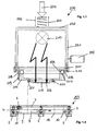
- the Figures 1.1 and 1.2 show in a sectional side view of a hand welder 200, which is intended for use with a positioning device 203.
- the hand welding device 200 according to the invention consists of a housing 201, which is shown as a one-piece variant. However, it is possible to manufacture the housing from several individual components. Above the housing 201, the possibility of a force introduction is shown by an arrow 204, which is exerted directly on a guided in a spring guide 206 spring 207. At the other end, the spring 207 rests on the upper housing cover 202, so that the force on the spring and the housing 201 is finally transferred to a An horrblende 215.
- the housing 201 can hereby be supported by a handle 205 additionally supportive.
- the introduced force serves to exert a pressure on the materials to be welded, namely until after the plasticization and cooling has hardened the joining zone has occurred.
- the spring 207 in this case it is possible to absorb pressure fluctuations in order to ensure a uniform pressure force by the Anticianblende 215.
- a radiation source 210 is arranged, which is symbolized by the two lightning arrows, the outgoing electromagnetic radiation is introduced through an existing shadow mask of An horrblende 215 directly into the materials to be welded, preferably plastic materials.
- the housing 201 is designed to be open at the bottom and closed by a flange 208 so far.
- the flange 208 is connected with the aid of a spacer ring 211 and distributed distribution bolts 216 with the housing.
- the flange disc 208 has a circumferential trough-shaped recess 209, which is provided for receiving a filled with an incompressible liquid tube 217.
- the hose 217 is in this case between the flange 208 and a positioning ring 214, wherein a fastening by circumferentially distributed springs 218 with screw 219 adjustment takes place.
- the springs 218 are in this case connected to the screw 219 at one end and rest at the other end in a recess of the flange 208, so that a quasi-elastic connection between the flange 208 and the positioning ring 214 is present.
- the positioning ring 214 serves as a support for a An horrblende 215, which is screwed by means of screws 220 with the positioning ring 214.
- the Anticianblende 215 rests here with a first larger radial portion in a recess 221 of the positioning ring 214 and is held by the screws 220.
- the pressure diaphragm 215 has, for example, segment-shaped openings 222, through which the electromagnetic radiation passes directly onto the plastic materials to be welded.
- a positioning device 203 which consists of a positioning ring 3 with a plurality of circumferentially distributed feet 4 and suction feet 5 located thereon.
- the suction feet 5 come here to lie directly on the plastic materials to be welded and allow a fixation of the positioning device 203 on the plastic materials.
- a vacuum device which is not shown, the air is sucked out of the suction feet 5 via a vacuum connection 6, so that the positioning device 203 can be fixed on the plastic.
- a Clothingsetzring 9 which is connected via webs 10 with the positioning ring 3, preferably in one piece. Between the webs 10 in this case a plurality of circumferentially distributed recesses 8 are formed.
- the attachment ring 9 has a bore 18 which is dimensioned in size so that the pressure plate 215 can be used. Through the bore 18 thus comes with a placement of the welder 200 on the fixed positioning 203, the pressure plate 215 to lie directly on the plastic materials.
- the particular advantage of this first embodiment is that with the help of the positioning device 203, first a fixation at the position to be welded of the plastic materials can be made, then the hand welding device 200 can be placed on the positioning device 203 with the help of the existing guide, wherein in Furthermore, it is ensured by the hose 217 filled with incompressible fluid that a uniform contact pressure is applied to the plastic material via the pressure diaphragm 215. In the event that the manual welder 200 should not be placed at right angles to the plastic material to be welded, thus a pressure equalization takes place and it is always ensured that a uniform contact pressure is present.
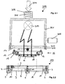
- the Figures 2.1 and 2.2 show a second embodiment of a manual welding device 300 with a housing 301 and a spring arranged above the housing 302, which is accommodated in a spring guide 306. Also on this spring 302 a force is exerted in the direction of arrow 304 to exert on the housing 301 and the existing Antikblende 16 a contact pressure on the materials to be welded.
- a radiation source 310 is arranged for electromagnetic radiation, which symbolized by the lightning arrows through the Antikblende 16 and the segment-shaped openings existing there can act directly on the plastic materials.
- the housing 301 has a handle 305, wherein the housing 301 is designed to be open at the bottom.
- the opening of the housing 301 is first closed by a spacer 311 and thereafter by a flange 14, wherein a screw connection by means of bolts 316 takes place.
- the flange 14 is part of a guide device 26, which in the further in the FIG. 1 known positioning device 203 can be used.
- the guide device 26 consists first of the bolted to the housing 301 flange 14, another flange 12 and a flange 7. Between the first and second flange 14, 12, a bearing element 11 is arranged, in each case in pairs, while between the second and third flange 7, 12, a second bearing element 13, also in pairs, is arranged.
- the two bearing elements 11, 13 are each arranged rotated by 90 ° to each other, so that a pivoting movement of the guide device 26 is given.
- the housing 301 can be used in case of need at an angle ⁇ 90 ° degrees with respect to the plastic plane to be processed.
- the guide device 26 in this case allows a pivoting movement of the housing 301 relative to the positioning device
- the positioning device 203 corresponds in an identical form of FIG. 1 known embodiment, wherein the pressure plate 16 is inserted into the bore 18.
- slippage of the manual welding device 300 can be excluded on the materials to be welded, wherein in addition by the pivoting mobility high flexibility with respect to a working angle.
- a uniform pressure force can thus be transmitted to the pressure diaphragm 16 and thus to the plastic material via the guide device 26.
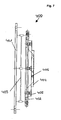
- FIG. 3 shows a perspective view of a first part of the positioning device 203, consisting of a first flange 14 for mounting on the welder, a second flange 12 and a third flange 7 as a guide ring.
- the flange 7 is used inter alia to attach the An horrblende 16, which is bolted via a mounting ring 15 with the flange 7.
- the individual flange discs 7, 12, 14 are connected to one another via bearing elements 11, 13, in such a way that in each case two paired bearing elements 11, 13 form a common axis and the bearing elements 11, 13 forming an axis between the first and second Flange 12, 14 and the second and third flange 7, 14 in this case are arranged offset by 90 ° to each other.
- the bearing elements 11, 13 themselves consist of a bearing bush 20 with a bearing journal 21, which has a cotter pin 22 and an enlarged collar 23 in the bearing bush 20 is attached. Furthermore, it can be seen from this view that the pressure diaphragm 16 has segment-like openings 24, through which the electromagnetic radiation passes into the absorbent layers of the lining material and / or the fastening and fixing points. Alternatively, there is the possibility that a glass pane transparent to electromagnetic radiation is used as a pressure diaphragm 16.
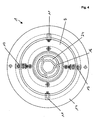
- FIG. 4 shows in a plan view of FIG. 3 known positioning device 203 with the flange 7, 12, 14 and the bearing elements 11, 13. From this view it can be seen that the pressure plate 16 is provided with segment-shaped openings 24, through which the electromagnetic radiation reaches the lining material.
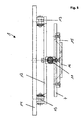
- FIG. 5 shows in a first side view of the positioning device 203 according to FIG. 3 , wherein from this view, the stepwise construction of the positioning device 203 can be seen, with an upper flange 14, which is intended for mounting to the welder and a central flange 12 and a lower flange 7. From this view, it is particularly clear that the upper and middle flange 12, 14 are connected to each other via the bearing elements 13, while the middle and lower flange 12, 7 are connected to each other via bearing elements 11.
- the offset by 90 ° position of the bearing elements 11, 13 in this case allows pivoting in all conceivable Aufsetzraumen the hand welder, so that a uniform contact pressure can be achieved in a false attached hand welding equipment.
- the Anyakblende 16 is in this case directly on the pressure surface 25 on the lining material. So that the pressure to be applied is transmitted by the hand welder alone through the Antikblende 16 is, as in particular from FIG. 1 can be seen, the positioning ring 7 is guided in the pocket-shaped recess 8, which allows regardless of the height of the positioning ring 3, a direct pressing the Antikblende 16 on the lining material. Only the exact position above the mounting and fixing point is determined by the positioning ring 3, whereby the exact position can be checked and corrected at any time by a visual inspection.
- the electromagnetic radiation source After placing the hand welder 2, the electromagnetic radiation source must be turned on for a short time until plasticization has taken place, and then the contact pressure is applied until the partially plasticized lining materials or fastening and fixing points have hardened to the extent that there is a permanent connection.
- FIG. 6 shows in a further side view of the positioning device 203 according to the structure of the preceding figures, in particular the FIG. 5 . From this representation, which compared to the FIG. 5 executed offset by 90 °, the connection of the middle and lower flange 12, 7 on the bearing elements 13 can be seen.
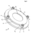
- FIG. 7 shows in a perspective view of the positioning device 203, namely a positioning ring 3, which is placed directly on the plastic materials to be welded by means of feet 4, which have on the head side suction cups 5, wherein via a vacuum connection 6, a negative pressure in the Saug Val 7 5 are generated can.
- the individual feet 4 are connected via a ring line, not shown, with the vacuum connection 6.
- the positioning device 203 here consists of a positioning ring 3 and a Aufsetzring 9 with a bore 18, which is further provided for receiving the An horrblende. Via webs 10, which are integrally formed integrally on the positioning ring 3, there is a connection with the Aufsetzring 9.
- the formed webs is formed between each two adjacent webs 10, a recess 8, which allows Aufsetzkontrolle the manual welding device.
- the length of the webs 10 was in this case chosen so that the hand welder with Anvikblende 16 can be used exactly in the positioning ring 3 and after putting on the welder the An réelleblende 16 comes to rest directly on the plastic material.
- the welding process itself is carried out with the aid of electromagnetic radiation, wherein the hand welding device 2 in various forms, depending on the type of electromagnetic radiation, can be constructed. With the help of the positioning device 203 All hand welders 2 can be used regardless of the type of electromagnetic radiation.
- FIG. 8 shows in a sectional side view of a further guide device 400, which can be used for example with the manual welder 300.
- the guide device 400 has a first flange 401, which is provided for screwing to the hand welding device, not shown. Between the flange 401 and another flange 402, an elastic body 403 is arranged, which, like the embodiment according to FIG. 2 allows a pivoting movement of the mounted hand welder to a small extent, while ensuring that the applied contact pressure is ensured evenly over the entire surface of the front Anvikblende 404.
- the An strigblende 404 is screwed with screws 405 to the flange 402 and has an outer dimension, which is formed corresponding to the bore 18 of the positioning device 203.
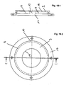
- FIGs 9.1 and 9.2 show in a plan view and a side view of the positioning device 203 with positioning ring 3, from which it can be seen that four suction cups 5 are arranged circumferentially distributed and via a ring channel 19 is a connection to the vacuum port 6.
- the annular channel 19 is formed in the positioning ring 3, which is used to receive the individual suction feet 5 and also serves to fasten the Aufsetzrings 9 via the webs 10.
- FIGS. 10.1 and 10.2 show in a plan view and a sectional side view of the step-shaped positioning ring 3 again in a single representation, from the cup-shaped training is visible. About the webs 10 in this case the positioning ring 3 is connected to the Aufsetzring 9, so that the pot-shaped configuration.
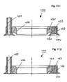
- This positioning device 450 consists of an annular disc 451 with a circumferential groove 452, in which a rubber ring 453 with V-shaped apart sealing lips 454 can be placed on the plastic material, not shown. Via a vacuum connection 455, the air can be sucked out below the rubber ring 453, so that the sealing lips 454 can be seeped to the plastic material.
- the upper part of the figure shows the positioning device 450 before the suction and the lower part figure after the suction with splayed sealing lips 454.
- this positioning device 450 also a definition of the hand welding devices 200 and 300 described can be done.
- the bore 456 can thus be placed centered on the plastic materials, the respective An horrblende the guide means, whereby the already described advantages arise that after determination of the positioning device 450 slipping of the hand welding device 200, 300 can be excluded.
Landscapes
- Engineering & Computer Science (AREA)
- Mechanical Engineering (AREA)
- Physics & Mathematics (AREA)
- Health & Medical Sciences (AREA)
- Electromagnetism (AREA)
- Toxicology (AREA)
- Lining Or Joining Of Plastics Or The Like (AREA)
Description
- Die Erfindung betrifft eine Positioniereinrichtung für ein Handschweißgerät, insbesondere für ein Kunststoffschweißgerät, umfassend zumindest eine dem Handschweißgerät zugeordnete Andruckblende und einem dem zu verschweißenden Material zugeordneten Positionierring.
- Gattungsgemäße Handschweißgeräte werden beispielsweise zur Verschweißung von Auskleidungsfolien für tragende Konstruktionen, wie Behälter, Apparate, Kanäle, Gehäuse oder Kolonnen, benötigt, die entweder aus Metall, gegebenenfalls mit einer nur bedingt beständigen Beschichtung versehen sind oder aus Kunststoff oder GFK bestehen. Die hierbei verwendeten Materialien sind in der Regel nicht säurebeständig oder unrein, sodass eine zusätzliche säure- oder laugenbeständige Auskleidung der Behälter erforderlich ist. Ferner wird eine Auskleidung dort erforderlich, wo mit korrosiven Gasen oder flüssigen Substanzen gearbeitet wird und die Gehäuseinnenwandungen diesen Gasen beziehungsweise Flüssigkeiten ausgesetzt sind. Darüber hinaus sind Auskleidungsmaterialien für hochreine Behälter (Semiconductor) und für hochbeständige Behälter (Chemie) sowie für Kolonnen und andere Apparate (Chemie) notwendig. Zum Korrosionsschutz der tragenden Konstruktion und insbesondere den Wänden werden die den Strömungsbereichen zugewandten Innenflächen daher mit Korrosionsschutzfolien (Auskleidungsmaterial; Inlinerfolie) aus Kunststoff verkleidet. Hierbei gelangt insbesondere der Kunststoff MFA, PFA oder FEP in Folienform zur Anwendung, weil dieser Kunststoff einen ausreichenden Korrosionsschutz bietet. Ferner kommen Kunststoffmaterialien infrage, welche zu Folien verarbeitet werden können und eine ausreichende chemische Resistenz aufweisen.
- Eine gattungsgemäße Positioniereinrichtung ist aus der
EP 0995 541 bekannt. - Damit ein umfassender Korrosionsschutz der tragenden Konstruktion gewährleistet ist, wird diese mit Auskleidungsmaterialien, vorzugsweise Kunststoffbahnen, vollflächig ausgekleidet, wobei die Auskleidungsmaterialien über eine Vielzahl von Befestigungs- oder Fixpunkten punktuell an der Wand innenfläche der tragenden Konstruktion gehalten werden. Die erforderlichen Befestigungs- oder Fixpunkte sind hierbei an der Innenwand der tragenden Konstruktion befestigt und werden zur Aufhängung genutzt, wobei üblicherweise pro m2 nur wenige Befestigungspunkte vorgesehen sind. Die Befestigungs- oder Fixpunkte bestehen nach dem bekannten Stand der Technik aus Schraubbolzen oder ähnlichen Metallteilen, welche mit der Gehäuseinnenwandung verbunden und zur Festlegung der Auskleidungsmaterialien unter Verwendung weiterer Hilfsmittel vorgesehen sind. Beispielsweise können die Befestigungs- oder Fixpunkte aus Metall mit einer metallischen Gehäuseinnenwandung verschraubt, verklebt oder verschweißt werden. Alternativ kommt der Einsatz von Kunststoffmaterialien in Betracht, welche in der Regel in gleicher Weise befestigt werden, wobei es auf das Material der tragenden Konstruktion ankommt, welche Befestigungsart gewählt wird. Kunststoffmaterialien weisen in der Regel eine höhere chemische Resistenz als metallische Standardlösungen auf, sodass die Befestigungspunkte meistens nachträglich zusätzlich mit einer Folie abgedeckt werden müssen, wenn offen liegende unreine Kunststoffe oder Metallteile in den Innenraum der Konstruktion ragen. Hierdurch ist ein vermeidbarer Arbeitsaufwand erforderlich.
- Die zur Befestigung vorgesehenen Auskleidungsmaterialien müssen dauerhaft mit der Wandinnenfläche der tragenden Konstruktion verbunden werden, insbesondere deshalb, weil aufgrund von Druckschwankungen der flüssigen oder gasförmigen Medien, welche beispielsweise in die tragende Konstruktion eingelassen werden, und den hierdurch entstehenden mechanischen Beanspruchungen eine ausreichende Haltekraft erforderlich ist. Zur Verschweißung der Auskleidungsmaterialen mit den Befestigungen und Fixpunkten werden Handschweißgeräte eingesetzt.
- Die verwendeten Befestigungs- und Fixpunkte bestehen aus einem kunststoffkompatiblen Trägermaterial, welches vorzugsweise lichttransparent ausgeführt ist und eine einseitig absorbierende Beschichtung aufweist. Die Beschichtung kann gegebenenfalls auch zweiseitig ausgebildet sein oder kann in einem Zwischenschritt durch beispielsweise ein Handschweißgerät aufgeschweißt werden, sodass ein Befestigungs- und Fixpunkt beispielsweise zur Befestigung einer oder zweier Inlinerfolien verwendet werden kann. Die absorbierende Beschichtung dient hierbei dazu, dass mit Hilfe der einzubringenden elektromagnetischen Strahlung eine Erwärmung erfolgt und dieser Energieeintrag auf das Material des Befestigungs- und Fixpunktes beziehungsweise die zu verbindenden Kunststoffmaterialien übertragen wird, sodass infolge der stattfindenden Plastifizierung eine Verbindung zwischen dem Material des Befestigungs- und Fixpunktes und der Inlinerfolien zustande kommt, wobei das Material im Wellenlängenbereich von 300 bis 2.500 nm nicht absorbierend ausgebildet ist und eine absorbierende Beschichtung im Wellenlängenbereich von 150 bis 2.500 nm, vorzugsweise 500 bis 1.500 nm, besonders bevorzugt von 800 bis 1.000 nm absorbiert. Das verwendete Material besitzt eine Dicke von 1,0 bis 5,0 mm, während die absorbierende Beschichtung eine Schichtdicke von 0,05 bis 0,5 mm, vorzugsweise 0,1 bis 0,4 mm und besonders bevorzugt von 0,2 bis 0,3 mm aufweist. Damit die Inlinerfolien einen Abstand zueinander einhalten weist das Material der Befestigungs- und Fixpunkte eine Dicke von 1,0 bis 10,0 mm, vorzugsweise 1,5 bis 5,0 mm, besonders bevorzugt 2,0 bis 4,0 mm auf, sodass nach dem Aufbringen einer zweiten Inlinerfolie ein Zwischenraum im Millimeterbereich entsteht.
- Durch die alleinige Verwendung von Kunststoff für die Befestigung- und Fixpunkte wird das Problem einer Zerstörung durch korrosive Gase infolge Permeation oder Flüssigkeiten bei Leckagen vermieden, wobei durch eine Verschweißung der Befestigungs- und Fixpunkte einerseits mit der Innenfläche der tragenden Konstruktion und andererseits mit dem Auskleidungsmaterial eine hochfeste und widerstandfähige Verbindung geschaffen wird. Vorzugsweise wird hierbei eine Verschweißung mit Hilfe von elektromagnetischer Strahlung vorgenommen, wobei einerseits die Befestigungs- und Fixpunkte aus einem Kunststoffmaterial bestehen und andererseits die Innenfläche der tragenden Konstruktion oder das Auskleidungsmaterial ebenfalls aus einem Kunststoff besteht, sodass im Falle einer ausreichenden Kompatibilität die Kunststoffe unmittelbar miteinander verschweißt werden können. Zu diesem Zweck ist ein korrespondierendes Teil der verwendeten Kunststoffmaterialien entweder mit einer absorbierenden Beschichtung versehen oder mit absorbierenden Partikeln angereichert. Soweit eine tragende Konstruktion beispielsweise aus einem Metall gefertigt wurde oder aus einem Kunststoffmaterial besteht, welches nicht verschweißbar ist, zum Beispiel GFK, erfolgt eine zusätzliche Auskleidung der Innenwände mit einer Kunststoffschicht, welche einerseits zum weiteren Schutz der tragenden Konstruktion dient und andererseits zum Verschweißen mit den Befestigungs- und Fixpunkten geeignet ist. Die verwendeten Auskleidungsmaterialien aus Kunststoff können anschließend nach dem Befestigen der Befestigungs- und Fixpunkte ebenso mit diesen verschweißt werden, sodass in der jeweiligen Konstruktion zusätzlich zur Innenfläche eine zweite innen liegende Inlinerfolie vorhanden ist, welche aus dem Auskleidungsmaterial besteht und beabstandet zur eigentlichen Innenfläche angeordnet ist. Durch die Verwendung von kompatiblen Kunststoffmaterialien können diese unmittelbar miteinander verschweißt werden, wobei die hierzu verwendeten Befestigungs- und Fixpunkte mit einer ersten Kontaktfläche einerseits mit der Innenfläche und mit einer zweiten Kontaktfläche andererseits mit dem Auskleidungsmaterial verschweißbar sind. Als Handschweißgerät kommen grundsätzlich alle denkbaren Geräte in Betracht, welche eine Verschweißung der Kunststoffmaterialien ermöglichen.
- Vorzugsweise werden die Befestigungs- und Fixpunkte aus einem lichttransparenten Kunststoffmaterial hergestellt, sodass mit Hilfe von elektromagnetischer Strahlung eine Verschweißung der Kunststoffmaterialien beziehungsweise der absorbierenden Schicht mit der Innenfläche oder dem Auskleidungsmaterial ermöglicht wird. Zu diesem Zweck wird vorzugsweise die Innenfläche aus einem lichtabsorbierenden Kunststoffmaterial hergestellt oder es wird eine Innenfläche aus einem Kunststoffmaterial verwendet, das zusätzlich mit einer absorbierenden Beschichtung versehen ist. Das Auskleidungsmaterial wird demgegenüber aus einem lichttransparenten Kunststoffmaterial gefertigt, damit eine nachträgliche Verschweißung mit Hilfe von beispielsweise elektromagnetischer Strahlung ermöglicht wird. In einem solchen Fall kann die Kontaktfläche der Abstandshalter mit einer lichtabsorbierenden Schicht versehen sein oder es wird ein lichtabsorbierender Abstandshalter verwendet, welcher durch seine Formgebung die Bestrahlung der hinteren Kontaktfläche zur Innenfläche hin gewährleistet.
- Durch diese Lösungen wird sichergestellt, dass die Abstandshalter mit der Innenfläche und/oder dem Auskleidungsmaterial durch elektromagnetische Strahlung verbindbar sind und somit mit Hilfe der Verschweißung eine dauerhafte Verbindung gewährleistet und darüber hinaus ein rationelles Arbeiten ermöglicht wird.
- Für die Wandfläche und das Auskleidungsmaterial können Standardthermoplaste, vorzugsweise PE, PP, PE-UHMW, oder teilfluorierte Thermoplaste, vorzugsweise PVDF, E-CTFE oder hochfluorierte Thermoplaste, vorzugsweise FEP, MFA, PFA oder modifiziertes PTFE, verwendet werden, wobei die absorbierende Beschichtung aus gleichen Kunststoffmaterialien oder bei PE-UHMW und modifiziertem PTFE aus artverwandten Kunststoffmaterialien bestehen kann.
- Die zur Verwendung vorgesehenen Kunststoffmaterialien als Auskleidungsmaterial besitzen in den meisten Fällen eine besonders glatte Oberfläche, sodass die zur Verschweißung vorgesehenen Handschweißgeräte sehr leicht abrutschen können und die Verschweißung nicht korrekt ausgeführt wird. Als Schweißbereich kommt hier vorzugsweise die Position der Befestigungs- und Fixpunkte infrage, welche beispielsweise eine Größe von cirka 3 bis 10 cm aufweisen können. Nach dem Verlegen des Auskleidungsmaterials besteht somit die Notwendigkeit mit Hilfe eines Handschweißgerätes exakt die Befestigungs- und Fixpunkte mit dem Auskleidungsmaterial zu verschweißen. Zu diesem Zweck wird ein Handschweißgerät auf das Auskleidungsmaterial aufgesetzt.
- Der vorliegenden Erfindung liegt die Aufgabe zugrunde, die Handhabung eines Handschweißgerätes wesentlich zu vereinfachen und eine sichere Verschweißung der Auskleidungsmaterialien mit den Befestigungs- und Fixpunkten zu ermöglichen.
- Erfindungsgemäß ist zur Lösung der Aufgabe vorgesehen, dass ein Positionierring auf dem zu verschweißenden Material festlegbar ist und eine in den Positionierring einsetzbare Andruckblende einen über dem Umfang gleichmäßig verteilten Druck auf die zu verschweißenden Materialien überträgt. Weitere vorteilhafte Ausgestaltungen der Erfindung ergeben sich aus den Unteransprüchen.
- Je nach Art des verwendeten Handschweißgerätes wird durch den vorgesehenen Schweißkopf das Auskleidungsmaterial und insbesondere der hinter dem Auskleidungsmaterial liegende Befestigungs- und Fixpunkte abgedeckt, sodass eine exakte Positionierung und spätere Kontrolle erheblich erschwert ist. Darüber hinaus besteht die Gefahr, dass das Handschweißgerät nach dem Aufsetzen durch Aufbringen des erforderlichen Anpressdruckes gegenüber dem Befestigungs- und Fixpunkt verrutscht und somit nur eine teilweise Verschweißung stattfindet. Durch den erfindungsgemäßen Positionierring, welcher zuvor auf dem zu verschweißenden Material festlegbar ist und eine in den Positionierring einsetzbare Andruckblende, welche unmittelbar dem Handschweißgerät zugeordnet ist, wird ein über den Umfang der Andruckblende gleichmäßig verteilter Druck aufgebracht. Hierdurch wird sichergestellt, dass das zu befestigende Auskleidungsmaterial gleichmäßig gegen den Befestigungs- und Fixpunkt gedrückt wird und somit eine sichere Verschweißung des Auskleidungsmaterials mit dem Befestigungs- und Fixpunkt erfolgen kann. In einem ersten Arbeitsschritt wird zunächst der Positionierring auf dem Auskleidungsmaterial befestigt und nach abschließender Kontrolle das Handschweißgerät auf diesen Positionierring aufgesetzt, um die erforderliche Verschweißung vorzunehmen. Hierdurch ist bereits sichergestellt, dass ein nachträgliches Verrutschen auf dem Ausgangsmaterial verhindert wird und darüber hinaus wird durch eine vorherige Kontrolle ein sicheres Aufsetzen auf das Auskleidungsmaterial in Höhe der Befestigungs- und Fixpunkte gewährleistet. Zu diesem Zweck wird die Andruckblende, welche dem Handschweißgerät zugeordnet ist, in den Positionierring eingesetzt, sodass über Positionierring und Andruckblende die Position des Handschweißgerätes eindeutig bestimmbar und festgelegt ist. Zur Vermeidung eines unterschiedlichen Anpressdruckes, beispielsweise wenn das Handschweißgerät nicht senkrecht zum Auskleidungsmaterial aufgesetzt wird, ist im Weiteren vorgesehen, dass die einsetzbare Andruckblende gegenüber dem Handschweißgerät druckausgleichend gelagert ist. Durch die vorgesehene erfindungsgemäße Lagerung der Andruckblende gegenüber dem Handschweißgerät ist somit auch bei einem nicht senkrechten Aufsetzen des Handschweißgerätes auf das Auskleidungsmaterial ein gleichmäßiger Anpressdruck gewährleistet, wobei die Andruckblende immer vollflächig in dem Positionierring einsitzt und somit unmittelbar flächig auf dem Auskleidungsmaterial aufliegt und den notwendigen Anpressdruck für die Verschweißung ermöglicht. Durch diese Maßnahmen wird ein gleichbleibender durchschnittlicher Abstand zwischen der elektromagnetischen Strahlungsquelle und der zu verschweißenden Ebene (Fokussierebene) eingehalten. Hierbei wird insbesondere die Dicke des Auskleidungsmaterials berücksichtigt, sodass die Fokussierebene unmittelbar hinter dem Auskleidungsmaterial liegt und damit eine sichere Verschweißung zwischen dem Befestigungs- und Fixpunkt und Auskleidungsmaterial gewährleistet ist. Soweit elektromagnetische Strahlungsquellen, wie beispielsweise Laser eingesetzt werden, deren Fokussierebene einstellbar ist, kommt es nicht auf die Einhaltung des Fokussierabstandes an.
- In besonderer Ausgestaltung der Erfindung ist vorgesehen, dass der Positionierring als Vakuumring ausgebildet ist und zumindest einen Vakuumanschluss für eine Vakuumpumpe und mehrere, vorzugsweise vier, Saugfüße aufweist, welche auf dem zu bearbeitenden Material mit Unterdruck festlegbar sind. Die aufgezeigte Lösung ermöglicht mit einfachsten technischen Hilfsmitteln den Positionierring für den vorgesehenen Schweißvorgang in der entsprechenden Position auf dem Auskleidungsmaterial zunächst aufzusetzen und nach Erzeugen eines Vakuums mit dem erforderlichen Unterdruck über die vier Saugnäpfe einen sicheren Halt für den Arbeitsvorgang zu gewährleisten.
- Alternativ besteht die Möglichkeit einen Positionierring mit einem umlaufenden Saugring zu verwenden, welcher ebenfalls auf dem Auskleidungsmaterial festlegbar ist, wobei über ein Vakuumanschluss ein Unterdruck erzeugt werden kann, welcher dazu führt, dass der Saugring über den gesamten Umfang auf dem Auskleidungsmaterial festlegbar ist.
- Zum Aufsetzen des Handschweißgerätes weist der Positionierring eine radiale Ausnehmung auf, in welche eine Führungseinrichtung mit Andruckblende einsetzbar ist. Zu diesem Zweck ist die Führungseinrichtung unmittelbar mit dem Handschweißgerät verbunden, wobei die Führungseinrichtung beispielsweise aus mehreren, vorzugsweise drei, Flanschscheiben bestehen kann. Eine erste Flanschscheibe dient zur Befestigung am Handschweißgerät, beispielsweise über eine Verschraubung. Die weitere diametral abgewandte Flanschscheibe ist als Führungsring ausgebildet und wird in die vorhandene Ausnehmung des Positionierringes eingesetzt. Zwischen beiden äußeren Flanschscheiben ist zumindest eine weitere dritte Flanschscheibe angeordnet, welche lediglich zur Verbindung der äußeren Flanschscheiben vorgesehen ist, und zwar über eine schwenkbewegliche Lagerung. Die mittlere Flanschscheibe ist hierbei mit den jeweils beiden benachbarten Flanschscheiben über zwei paarweise angeordnete Lagerelemente verbunden, welche eine Schwenkachse bilden, sodass die mittlere Flanschscheibe einerseits gegenüber dem Führungsring und andererseits gegenüber dem Handschweißgerät verschwenkbar gestaltet ist. Damit eine Anlage vollflächig über den gesamten Kreisumfang des Führungsringes mit gleichmäßiger Andruckkraft gewährleistet ist, ist die Schwenkachse der ersten und zweiten Flanschscheibe und die der zweiten Flanschscheibe und dem Führungsring um 90° versetzt zueinander angeordnet. Hierdurch besteht die Möglichkeit einen Ausgleich des Handschweißgerätes gegenüber der zu verschweißenden Fläche des Auskleidungsmaterials entlang einer X- und Y-Achse schwenkbeweglich zu gestalten. Die dem Positionierring zugeordnete Flanschscheibe kann hierbei zweiteilig ausgebildet sein und besteht aus der Flanschscheibe und einer Andruckblende, welche miteinander verbunden sein können, wobei die Andruckblende unmittelbar auf dem Auskleidungsmaterial zu liegen kommt. Hierbei handelt es sich somit um eine senkrecht zur Schweißebene bewegliche Anordnung des Handschweißgerätes.
- Die vorgesehenen Lagerelemente können hierbei jeweils aus zumindest zwei Lagerschalen mit einer Drehachse bestehen, wobei die Drehachse einen überstehenden Kragen und einen Splint aufweist, sodass quasi eine unverlierbare Einheit geschaffen wird.
- Alternativ besteht die Möglichkeit, dass die Flanschscheiben jeweils über zumindest drei hydraulische Kolben untereinander verbunden sind, sodass mit Hilfe der hydraulischen Kolben ebenfalls ein gleichmäßiger Anpressdruck erzielt werden kann, wenn beispielsweise das Handschweißgerät nicht im rechten Winkel zum Auskleidungsmaterial aufgesetzt worden ist. Die hydraulischen Kolben können hierzu gegebenenfalls durch eine gemeinsame Druckverbindung einen Druckausgleich ermöglichen, sodass eine selbsttätige Druckanpassung erfolgen kann und somit die Flanschscheiben den Anpressdruck gleichmäßig auf das Auskleidungsmaterial übertragen. Anstelle der hydraulischen Kolben könnte ebenso zumindest ein ringförmiger Schlauch eingesetzt werden, welcher die einzelnen Flanschscheiben miteinander verbindet, wobei der Schlauch mit einem zumindest teilweise inkompressiblen Medium gefüllt ist, sodass auch bei dieser Ausgestaltung ein gleichmäßiger Anpressdruck über die gesamte Andruckfläche erzielbar ist.
- Alternativ zu den bisherigen Vorschlägen besteht ferner die Möglichkeit, dass die dem Positionierring zugewandte Flanschscheibe und/oder die Andruckblende über elastische Ausgleichselemente verbunden sind, sodass auch durch diese Lösung ein gleichmäßiger Anpressdruck erzielbar ist. Als elastisches Ausgleichselement kommt beispielsweise zwischen Flanschscheibe und Andruckblende ein mit inkompressibler Flüssigkeit gefüllter Schlauch infrage, welcher einerseits mit der Andruckblende und andererseits mit der Flanschscheibe verbunden ist, sodass ein über das Handschweißgerät vorgenommener Anpressdruck über den mit einer inkompressiblen Flüssigkeit gefüllten Schlauch auf die Andruckblende übertragen wird. Als weitere Alternative besteht die Möglichkeit die Andruckblende auf der zur Anlage vorgesehenen Außenseite zumindest partiell mit gummielastischen Auflagen zu versehen, sodass über diese elastischen Auflagen ebenfalls eine gleichmäßige Flächenpressung erzielt werden kann, wobei nicht ausgeschlossen ist, dass mehrere der vorgeschlagenen Lösungen miteinander kombiniert werden. Insbesondere kann die vorgesehene Andruckblende radial außen liegende und/oder radial innen liegende Ausgleichselemente aufweisen. Alternativ können die elastischen Ausgleichselemente auch zwischen den Flanschscheiben angeordnet sein. Hierbei handelt es sich um eine relativ starre Ausführung, welche keine Verschwenkungsmöglichkeit besitzt, jedoch mit Hilfe der elastischen Ausgleichselemente ebenfalls für einen gleichmäßigen Anpressdruck an das Auskleidungsmaterial geeignet ist.
- Durch die Verbindung der Flanschscheiben mit der vorgesehenen Lagerung besteht somit die Möglichkeit ein nicht im rechten Winkel zum Auskleidungsmaterial aufgesetztes Handschweißgerät trotzdem zur Herstellung einer optimalen Schweißverbindung zu verwenden. Durch die schwenkbewegliche Lagerung der Flanschscheiben gegenüber der Längsachse des Handschweißgerätes wird der erforderliche Druck in Richtung auf das Auskleidungsmaterial ausgeglichen und somit eine Flächenpressung mit einer Druckverteilung über 360° der Andruckblende erzielt, sodass eine gleichmäßige Flächenpressung vorliegt.
- Vorzugsweise wird der Anpressdruck über die dritte, als Führungsring ausgebildete Flanschscheibe und eine Andruckblende auf das Auskleidungsmaterial erzeugt, wobei die Andruckblende mit der Flanschscheibe verbunden, vorzugsweise verschraubt ist. Die Andruckblende selbst ermöglicht den Durchtritt von elektromagnetischer Strahlung auf das zu bearbeitende Auskleidungsmaterial, sodass die erforderliche Plastifizierung der Kunststoffmaterialien exakt im vorzunehmenden Schweißbereich mit geringer Dosierung erfolgen kann und das Auskleidungsmaterial darüber hinaus im angrenzenden Bereich seine Struktur beibehält.
- In weiterer Ausgestaltung der Erfindung ist vorgesehen, dass die Andruckblende als Lochmaske mit kreisringförmig angeordneten segmentartigen Durchbrüchen ausgestaltet ist, durch welche hindurch die elektromagnetische Strahlung in die Kunststoffmaterialien gelangt und von den absorbierenden Schichten in Wärme umgewandelt wird. Alternativ besteht die Möglichkeit, dass die Andruckblende zumindest teilweise aus einem Material besteht, welches für elektromagnetische Strahlung transparent ist, beispielsweise Glas oder ein transparenter Kunststoff. Durch die vorgesehenen Ausgestaltungen der Andruckblende wird somit die elektromagnetische Strahlung auf eine geringe Fläche, welche an die Größe der Befestigungs- und Fixpunkte angepasst ist, begrenzt, sodass insbesondere die benachbarten Flächen des Auskleidungsmaterials nicht erwärmt werden und somit in ihrer Struktur erhalten bleiben. Hierdurch wird insbesondere die Elastizität der Materialien nur in geringem Maße beeinflusst und darüber hinaus eine unerwünschte Verformung des Auskleidungsmaterials in der Nähe der Befestigungs- und Fixpunkte verhindert. Durch die konstruktive Ausgestaltung der Positioniereinrichtung, entweder als starre oder als schwenkbewegliche Lösung wird in jedem Fall sichergestellt, dass ein gleichmäßiger Anpressdruck auf das Auskleidungsmaterial ausgeübt wird. Insbesondere wird im Weiteren sichergestellt, dass die Fokussierebene zwischen der elektromagnetischen Strahlungsquelle und der Schweißebene eingehalten wird, soweit dies für die elektromagnetische Strahlungsquelle erforderlich ist.
- Ein wesentlicher Vorteil bei der Verwendung der eingesetzten Handschweißgeräte und der Positioniereinrichtung besteht darin, dass die Kunststoffmaterialien und Schweißmitteln nur über einen begrenzten Bereich des Querschnittes plastifiziert werden, wobei sich dieser Bereich im Wesentlichen auf den Bereich der Befestigungs- und Fixpunkte erstreckt. Hierdurch ist der erforderliche Energieeintrag zur Erwärmung der verwendeten Kunststoffmaterialien und des Schweißmittels wesentlich geringer als bei herkömmlichen Schweißverfahren, wobei die zu bearbeitenden Kunststoffmaterialien aufgrund der geringen Plastifizierung nicht dauerhaft verformt werden und somit eine Beschädigung der Auskleidungsmaterialien, beispielsweise in Form von Inlinerfolien, ausgeschlossen werden kann. Darüber hinaus kann das Handschweißgerät auf den Auskleidungsmaterialien aufliegend verwendet werden, ohne dass Beschädigung der Auskleidungsmaterialien eintreten. Der hierbei erforderliche Anpressdruck wird ohne Probleme über die Auskleidungsmaterialien auf die tiefer liegenden Kunststoffmaterialien, insbesondere die Befestigungs- und Fixpunkte übertragen, welche als Gegenhalter dienen. Darüber hinaus wird durch die nur begrenzte Plastifizierung der vorgenannten Auskleidungsmaterialien der Anpressdruck nur für einen geringen Zeitraum benötigt, da sich sowohl das Schweißmittel als auch die Auskleidungsmaterialien durch schnelles Abkühlen relativ schnell verbinden lassen.
- Ein weiterer wesentlicher Vorteil des Handschweißgerätes mit Positioniereinrichtung besteht darin, dass der geringe erforderliche Energieeintrag zu keiner Verformung der Kunststoffmaterialien führt und insbesondere die Bildung von Schwachstellen aufgrund von Querschnittsreduzierungen vermieden werden kann. Der Energieeintrag kann mit dem Handschweißgerät so gering wie möglich gehalten werden, wobei durch die Verwendung eines elektromagnetischen Strahlungskopfes eine genaue Dosierung erfolgen kann und die aufzubringende Energie unmittelbar in eine absorbierende Beschichtung eingebracht wird. Ferner kann der Anpressdruck so gering wie möglich gehalten werden, wobei eine manuelle Andruckkraft von Hand ausreichend ist.
- Die zum Einsatz kommenden Kunststoffmaterialen können thermostabile Additive in Form von Partikeln aufweisen, welche lasersensitiv oder infrarotsensitiv sind und aus organischen und anorganischen Materialien mit einer Mindesttemperaturstabilität bestehen, wobei die Temperatur den Verarbeitungstemperaturen der verwendeten Kunststoffmaterialien entspricht und wobei die Additive in Abhängigkeit des Wärmeeinwirkungsverfahrens beispielsweise aus Farbmitteln in Form von Farbstoffen oder Farbpigmenten, wie Rußteilchen oder Glimmer mit Zinn-Antimonbeschichtung, bestehen können, um eine Absorbtion der elektromagnetischen Strahlung zu ermöglichen.
- Die in der Beschichtung absorbierenden thermostabilen Additive bestehen hauptsächlich ebenfalls aus infrarotsensitiven oder lasersensitiven Partikeln, vorzugsweise organischen oder anorganischen Materialien mit einer Mindesttemperaturstabilität, die den Verarbeitungstemperaturen der verwendeten Kunststoffmaterialien entsprechen und in Abhängigkeit des Wärmeeinwirkungsverfahrens, beispielsweise aus Farbpigmenten, wie Rußteilchen oder Glimmer mit Zink-Antimonbeschichtung bestehen. Ähnlich verhält es sich mit den absorbierenden Kunststoffmaterialien die auf die Wandfläche aufgeklebt werden. Auch bei diesen Kunststoffmaterialien werden entsprechende thermostabile Partikel wie bei der absorbierenden Beschichtung eingesetzt. Die hierbei verwendeten Kunststoffmaterialen und Beschichtungen absorbieren elektromagnetische Strahlung im Wellenlängenbereich von 150 bis 2.500 Nanometer, vorzugsweise 500 bis 1.500 Nanometer, besonders bevorzugt von 800 bis 1.000 Nanometer.
- Als mögliche elektromagnetische Strahlungsquelle, kommt ein Festkörperlaser, ein Gaslaser, Halbleiterlaser oder eine Infrarotquelle, beispielsweise eine Xenon-Kurzbogenlampe in Frage oder es wird ein CO2-Laser verwendet. Alternativ kann eine Mikrowellenstrahlung oder ein Induktionsschweißverfahren angewendet werden. Sämtliche der vorgenannten Geräte erzeugen elektromagnetische Strahlung, die dazu genutzt werden können, um den Fügebereich der Behälterwandungen auszukleiden, damit die Kunststoffmaterialien nur insoweit plastifiziert werden, das eine sichere Schweißverbindung geschaffen wird.
- Um den Anforderungen der Berufsgenossenschaft Rechnung zu tragen, ist in weiterer Ausgestaltung vorgesehen, dass die elektromagnetische Strahlung des Strahlungskopfes innerhalb einer geschlossenen Wandung oder über einen Lichtleiter dem Fügebereich, welcher durch das Schweißmittel und die Kunststoffmaterialien gebildet wird, zuführbar ist. Diese Vorkehrung ist beispielsweise dann erforderlich, wenn als elektromagnetische Strahlungsquelle ein Laser zum Einsatz kommt.
- Beim Induktionsschweißen wird die zum Schweißen notwendige Wärme mittels eines alternierenden Magnetfeldes in die Fügezone eingetragen. Die Hauptphasen dieses Verfahrens sind Aufheizen, Konsolidieren unter Druck sowie Abkühlen, wobei die Haupteinflussparameter durch den Konsolidierungsdruck und die Temperaturen der Fügezone bestimmt sind. Beim Verschweißen von Kunststoffmaterialien ist ein Schweißzusatzstoff erforderlich, der die Energie eines elektromagnetischen Feldes in Wärme umsetzt. Dieser Schweißzusatzstoff, im Weiteren als Füllstoff bezeichnet, bleibt dauerhaft in der Schweißzone.
- Als mögliche Füllstoffe kommen unter anderem ferromagnetische Stoffe infrage, wobei insbesondere die Verwendung von Nanopartikeln oder Mahlgut möglich ist. Als Nanopartikel oder Nanoteilchen bezeichnet man einen Verbund von wenigen bis einigen tausend Atomen oder Molekülen. Der Name hat hierbei einen direkten Bezug auf deren Größe die typischerweise bei 1 bis 100 Nanometern liegt. Nanopartikel können sowohl auf natürlichen Wege als durch synthetische Verfahren hergestellt werden, die gezielt mit neuen Eigenschaften oder Funktionalitäten ausgestattet sind, wie zum Beispiel elektrische Leitfähigkeit, chemische Reaktivität. Synthetische Nanopartikel können entsprechend ihrer chemischen und physikalischen Eigenschaften untergliedert werden. In der Forschung und Anwendung sind folgende Gruppen verbreitet:
- Kohlenstoffhaltige Nanopartikel, Metalloxide, Titandioxid, Aluminiumoxid, Eisenoxid, Zinkoxid sowie Zeolithe und andere auf Silizium basierende mesoporöse Materialien wie MCM-41 oder SBA-15, Halbleiter, Metalle, Metallsulfide und Polymere wie Dendrimere und Blockcopolymere, wobei die kohlenstoffhaltigen Nanopartikel in unterschiedlichen Formen vorliegen können, beispielsweise als Fullerene, Nanoröhrchen oder Cabon black (Rußpartikel).
- Die Nanopartikel oder das Mahlgut kann eine thermische Anregung durch ein Magnetfeld oder ein elektrisches Feld erfahren, wobei ein Magnetfeld eine Bewegung der Nanopartikel in einem Stoff hervorruft, während elektrische Felder eine Anregung der Elektronen hervorrufen. Beide Maßnahmen führen zu einer Erwärmung der Nanopartikel oder des Mahlguts aufgrund der entstehenden Reibung.
- Eine Ummagnetisierung eines magnetisierten ferromagnetischen Stoffes erfolgt bei normalen Materialien mit vielen Weiss'chen Bezirken durch die Verschiebung der Potentialwälle zwischen den einzelnen Domänen, dass heißt die magnetischen Momente können sich an den Grenzen des einen Weiss'schen Bereich annähern und gehören dann zur benachbarten Domäne. Sinkt nun die Größe der Teilchen unterhalb der Größe der Weiss'schen Bereiche besteht der betreffende Partikel nur aus einem Weiss'schen Bereich. In solchen "Single domain particels" ist eine Verschiebung eines Potentialwalls nicht möglich, da kein Wall zwischen zwei Domänen besteht und es somit keine Wahrscheinlichkeit für ein antiparallel ausgerichtetes atomares magnetischen Moment gibt. Dass heißt in Einzeldomänenpartikeln können sich die Spins nur kollektiv ändern, was sich in einer sehr hohen Koerzivitätsfeldstärke niederschlägt.
- Kristallite von Ferromagnetika kann man sich aus Domänen zusammengesetzt vorstellen. Innerhalb dieser Domänen oder Weiss'chen Bezirke sind die atomaren magnetischen Momente parallel ausgerichtet. Das Volumen der Weiss'chen Bereiche liegt typischerweise bei 10-4 bis 10-6 mm3.
- Bringt man einen ferromagnetischen Stoff in ein äußeres Magnetfeld, so richten sich die magnetischen Momente der Weiss'schen Bezirke parallel zum äußeren Magnetfeld aus. Es erfolgt demzufolge eine Magnetisierung. Die Magnetisierung wächst mit steigender Feldstärke des äußeren Magnetfeldes bis zu einer Sättigungsfeldstärke, bei der eine vollständige Ausrichtung der Elektronenspins erreicht ist. Lässt man anschließend die Feldstärke des äußeren Magnetfeldes wieder bis auf null sinken, folgt die Magnetisierung nicht der ursprünglichen Kurve, sondern entlang einer Hysterese-Scheife. Bei der Feldstärke = 0 bleibt eine mehr oder weniger starke Remanenzmagnetisierung erhalten, sodass der ferromagnetische Stoff in einen Permanentmagneten umgewandelt wird. Erst bei Erreichen der Koerzivitätsfeldstärke, die antiparallel zur Magnetisierung des Stoffes ausgerichtet ist, geht die Magnetisierung der Probe auf null zurück. Steigt die Feldstärke des äußeren Magnetfeldes weiter bis auf einen Wert an, so wird die negative Sättigungsmagnetisierung erreicht. Verringert man nun wieder die Feldstärke, dreht deren Richtung um und vergrößert sie dann sukzessive. Diese Eigenschaften sind ferromagnetischen Stoffen imanent, wobei durch die Änderung des Magnetfeldes beispielsweise mit Hilfe einer Induktionsspule diese Möglichkeit zur Erwärmung ferromagnetischer Stoffe ausgenutzt werden kann. Hierbei können die ferromagnetischen Stoffe aus beispielsweise einem metallischen Mahlgut bestehen oder es können Nanopartikel eingesetzt werden, die weitere positive Eigenschaften aufweisen. Grundsätzlich ist von einer anderen Isotropie magnetischer Nanopartikel auszugehen und dies hat einen großen Einfluss auf deren Koerzivität. Bei magnetischen Nanopartikel spielen hauptsächlich die Kristalle und Partikelformationsisotropie eine Rolle. Aber auch Anisotropien, die durch Austausch zwischen dem Kern und der Hülle verursacht werden, dürfen im Einzelfall nicht vernachlässigt werden. Magnetokristalline Anisotropie wird durch die Orbitalspin-Kopplung und die energetisch bevorzugte Ausrichtung der Magnetisierung entlang einer bevorzugten Achse verursacht. Die Koerzivitätsfeldstärke eines Nanophasenmaterials ist proportional zur Anisotropie, sodass diese Materialien als Füllstoffe für Induktionsschweißungen verwendet werden können. Eine polykristalline Probe von Füllstoffen besitzt aufgrund der willkürlichen Orientierung der Teilchen keine Nettoanisotropie. Jedoch können nicht sphärische Teilchen eine Partikelformanisotropie zeigen, da es leichter ist ein zylindrisches Teilchen entlang der Kante als entlang der kurzen Kante zu magnetisieren. Die Abweichung von der sphärischen Form muss nicht besonders stark ausgeprägt sein, so bewirkt eine Abweichung von 1,1 bis 1,5% von der Kugelform schon eine Vervierfachung der Koerzivitätsfeldstärke.
- Besonders interessant in diesem Zusammenhang sind die Eigenschaften von Nanopartikeln, welche magnetisch, ferrimagnetisch, ferromagnetisch, antiferromagnetisch oder supraparamagnetisch sein können. Der Superparamagnetismus in Nanopartikeln wird durch das Absinken des Teilchenvolumens weiter begründet, sodass die atomaren magnetischen Momente immer stärker durch die thermische Bewegung der Teilchen beeinflusst werden und sich nicht weiter parallel ausrichten können. Es kommt zu Superparamagnetismus. Superparamagnetische Teilchen verhalten sich genauso wie paramagnetische Teilchen, jedoch haben sie ein erheblich größeres magnetisches Moment. Unterhalb einer sogenannten Blocktemperatur verhalten sich diese Stoffe wieder ferromagnetisch. Superparamagnetische Stoffe zeigen keine Hystereseschleife, sodass sie experimentell leicht von ferromagnetischen Teilchen unterschieden werden können. Die Eigenschaft der Nanopartikel hängt jedoch zum Beispiel von der erwähnten Blocktemperatur und von der Form der Teilchen ab. Beispielsweise können stäbchenförmige magnetische Nanopartikel mit einer Abmessung von 2 x 10 nm eine Blocktemperatur von nur 110 K besitzen, kugelförmige Teilchen mit einem Durchmesser von 2 nm jedoch eine von 12 K.
- Bei der Synthese von magnetischen Nanopartikeln wird man vor einer Reihe von Problemen gestellt. Um ein einheitliches Verhalten der Nanopartikel zu erhalten ist es von essentieller Wichtigkeit, einige Parameter möglichst genau zu steuern. Zum Einen ist es wünschenswert eine möglichst enge Größenverteilung der Partikel zu erhalten, da das magnetische Verhalten von Nanopartikeln maßgeblich durch deren Größe bestimmt wird. Durch gängige Syntheseverfahren kann man die Größenverteilung nur bis auf eine Abweichung von etwa 10% einengen. Im Allgemeinen werden jedoch Fraktionen benötigt, deren Abweichung in der Größenverteilung bei weniger als 5% liegen. Ein gängiges Verfahren ist die fraktionierte Flockung, durch Zugabe eines reinen Lösungsmittels zu einer Probe von Nanopartikeln von unterschiedlicher Größe konglomerieren die größten Partikel, da diese die größten van der Waals Anziehungskräfte besitzen. Das Konglomerat kann dann durch Zentrifugieren abgetrennt und der Vorgang wiederholt werden.
- Ein weiterer Parameter ist die Kristallinität der Produkte. Wünschenswert ist eine hohe Kristallinität, um eine möglichst hohe Magnetisierung zu erreichen. Aber auch die Beeinflussung der Kristallstruktur ist ein wichtiger Parameter, da man über ihn die Anisotropie der magnetischen Nanopartikel steuern kann. Im Allgemeinen erreicht man sowohl die Erhöhung der Kristallinität als auch die Beeinflussung der Kristallstruktur durch einen kontrollierten Alterungsprozess, den man zum Beispiel durch Erwärmen auf eine bestimmte Temperatur über eine gewisse Dauer erreichen kann. Zur Herstellung in der einzelnen Nanopartikeln sind verschiedene Verfahren bekannt auf die hier nicht im Einzelnen eingegangen werden kann.
- Zur Verbindung unterschiedlichster Kunststoffmaterialien ist die Verwendung von Nanopartikeln als Füllstoff mit ihren magnetischen, ferrimagnetischen, ferromagnetischen, antiferromagnetischen oder supraparamagnetische Eigenschaften besonders geeignet, wobei der Füllstoff nanoskalige, magnetische oder oxidische Partikel enthält, die aus aggregierten Primärpartikeln bestehen können oder wobei der Füllstoff aus Ferriten, Oxiden oder Metallmischoxiden bestehen kann. Die Teilchengröße liegt typischerweise zwischen 1 und 500 nm, insbesondere zwischen 2 und 100 nm.
- Eine Anregung der Nanopartikeln kann beispielsweise durch Mikrowellenstrahlung mit einer Frequenz von 1,5 bis 10 GHz, vorzugsweise im Bereich von 2 bis 3 GHz erfolgen, jedoch sind andere elektromagnetische Strahlungen ebenfalls verwendbar, durch welche die Eigenschaften der Nanopartikel als Füllstoffe ebenfalls ausgenutzt werden können und zu einer Erwärmung der zu verschweißenden Materialien, vorzugsweise Kunststoffmaterialien, führt.
- Alternativ zu den Nanopartikeln können verschiedene Metalle als Mahlgut den Kunststoffmaterialien in angereicherter Form zugegeben werden, sodass mit Hilfe eines elektromagnetischen Feldes unter Berücksichtigung der sich durch die Feldänderung ergebenden Bewegungen innerhalb des angereicherten Materials zu einer Erwärmung führen und somit zur Verschweißung verschiedener Kunststoffmaterialien herangezogen werden können. Hierbei sollte eine elektromagnetische Strahlung verwendet werden, welche typischer Weise im Resonanzbereich der verwendeten Nanopartikel oder des Mahlgutes liegt, um einen hohen Energieeintrag zu erzielen, wobei durch gezielte Zugabe von Nanopartikeln eine Änderung der Resonanzfrequenz erfolgen kann.
- Der besondere Vorteil von Nanopartikeln oder Mahlgut besteht hierbei darin, dass auf die Verwendung von transparenten Kunststoffmaterialien verzichtet werden kann und stattdessen gegebenenfalls preiswertes Kunststoffmaterial mit entsprechender Anreichung verwendet werden kann. Hierbei reichen Anreichungen von Nanopartikeln von typischerweise 1 bis 5%, vorzugsweise 2 bis 3%, aus, um mit Hilfe einer Induktionsvorrichtung oder einer Mikrowellenbestrahlung eine Verschweißung durchzuführen. Die Verwendung von Mahlgut, insbesondere fein gemahlenem Metall (Metallstaub) ist ebenfalls aufgrund der Dipolwirkung für Compounds geeignet. Insbesondere wird im Weiteren durch die Mikrowellenbestrahlung oder Induktionsschweißung aufgrund der verwendeten Energiequellen eine hohe Arbeitssicherheit gewährleistet.
- Die Erfindung wird im Weiteren anhand der Figuren näher erläutert.
- Es zeigt
- Fig. 1
- in einer geschnittenen Seitenansicht ein erstes Ausführungsbeispiel für ein Handschweißgerät mit Schlauchring und Andruckblende sowie einer davon abgesetzten Positioniereinrichtung, bestehend aus einem Positionierring und einem Aufsetzring,
- Fig. 2
- in einer geschnittenen Seitenansicht ein zweites Ausführungsbeispiel für ein Handschweißgerät mit Flanschscheiben und einer davon abgesetzten Positioniereinrichtung, bestehend aus einem Positionierring und einen Aufsetzring,
- Fig. 3
- in einer perspektivischen Ansicht die an das Handschweißgerät anschraubbaren Flanschscheiben mit Andruckblende,
- Fig. 4
- in einer Draufsicht die Flanschscheiben gemäß
Figur 3 , - Fig. 5
- in einer ersten Seitenansicht die Anordnung der Flanschscheiben gemäß
Figur 3 , - Fig. 6
- in einer weiteren Seitenansicht die Flanschscheiben gemäß
Figur 3 , - Fig. 7
- in einer Seitenansicht die an das Handschweißgerät anschraubbaren Flanschscheiben mit Andruckblende und Schlauch,
- Fig. 8
- in einer perspektivischen Ansicht eine Positioniereinrichtung mit einem Positionierring mit Saugfüßen,
- Fig. 9
- in einer Draufsicht und Seitenansicht die Positioniereinrichtung gemäß
Figur 8 , - Fig. 10
- in einer Draufsicht und Seitenansicht die Zentrierscheibe der Positioniereinrichtung und
- Fig. 11
- in einer geschnittenen Seitenansicht eine Positioniereinrichtung mit Saugring.
- Die
Figuren 1.1 und 1.2 zeigen in einer geschnittenen Seitenansicht ein Handschweißgerät 200, welches zur Verwendung mit einer Positioniereinrichtung 203 vorgesehen ist. Das erfindungsgemäße Handschweißgerät 200 besteht aus einem Gehäuse 201, welches als einteilige Variante dargestellt ist. Es besteht jedoch die Möglichkeit das Gehäuse aus mehreren Einzelkomponenten zu fertigen. Oberhalb des Gehäuses 201 ist durch einen Pfeil 204 die Möglichkeit einer Krafteinleitung dargestellt, welche unmittelbar auf eine in einer Federführung 206 geführte Feder 207 ausgeübt wird. Anderenends ruht die Feder 207 auf der oberen Gehäuseabdeckung 202, sodass die Kraft über die Feder und das Gehäuse 201 letztendlich auf eine Andruckblende 215 übertragen wird. Das Gehäuse 201 kann hierbei durch einen Handgriff 205 zusätzlich unterstützend gehalten werden. Die eingeleitete Kraft dient dazu einen Druck auf die zu verschweißenden Materialien auszuüben, und zwar solange bis nach erfolgter Plastifizierung und Abkühlung eine Aushärtung der Fügezone eingetreten ist. Mit Hilfe der Feder 207 besteht hierbei die Möglichkeit Druckschwankungen aufzufangen, um eine gleichmäßige Andruckkraft durch die Andruckblende 215 zu gewährleisten. - Innerhalb des Gehäuses ist eine Strahlungsquelle 210 angeordnet, welche durch die beiden Blitzpfeile symbolisiert wird, wobei die ausgehende elektromagnetische Strahlung durch eine vorhandene Lochmaske der Andruckblende 215 unmittelbar in die zu verschweißenden Materialien, vorzugsweise Kunststoffmaterialien, eingebracht wird. Im gezeigten Ausführungsbeispiel ist das Gehäuse 201 nach unten offen gestaltet und durch eine Flanschscheibe 208 insoweit verschlossen. Die Flanschscheibe 208 wird unter Zuhilfenahme eines Distanzringes 211 und umgangsverteilter Schraubbolzen 216 mit dem Gehäuse verbunden. Die Flanschscheibe 208 besitzt eine umlaufende muldenförmige Vertiefung 209, welche zur Aufnahme eines mit einer inkompressiblen Flüssigkeit gefüllten Schlauches 217 vorgesehen ist. Der Schlauch 217 liegt hierbei zwischen der Flanschscheibe 208 und einem Positionierring 214, wobei eine Befestigung durch umfangsverteilte Federn 218 mit Schraubverstellung 219 erfolgt. Die Federn 218 sind hierbei mit der Schraubverstellung 219 einenends verbunden und ruhen anderenends in einer Vertiefung der Flanschscheibe 208, sodass eine quasi elastische Verbindung zwischen der Flanschscheibe 208 und dem Positionierring 214 vorliegt. Der Positionierring 214 dient im Weiteren als Träger für eine Andruckblende 215, welche mittels Schrauben 220 mit dem Positionierring 214 verschraubt ist. Die Andruckblende 215 ruht hierbei mit einem ersten größeren radialen Abschnitt in einer Vertiefung 221 des Positionierrings 214 und wird durch die Schrauben 220 gehalten. Die Andruckblende 215 weist beispielsweise segmentförmige Durchbrüche 222 auf, durch welche die elektromagnetische Strahlung unmittelbar auf die zu verschweißenden Kunststoffmaterialien gelangt.
- Unterhalb des Handschweißgerätes ist eine Positioniereinrichtung 203 dargestellt, welche aus einem Positionierring 3 mit mehreren umfangsverteilten Füßen 4 und daran befindlichen Saugfüßen 5 besteht. Die Saugfüße 5 kommen hierbei unmittelbar auf den zu verschweißenden Kunststoffmaterialien zu liegen und ermöglichen eine Fixierung der Positioniereinrichtung 203 auf den Kunststoffmaterialien. Zu diesem Zweck wird mit Hilfe eines Vakuumgerätes, welches nicht dargestellt ist, aus den Saugfüßen 5 über einen Vakuumanschluss 6 die Luft abgesaugt, sodass die Positioniereinrichtung 203 auf dem Kunststoff festlegbar ist. Unterhalb des Positionierrings 3 befindet sich ein Aufsetzring 9, welcher über Stege 10 mit dem Positionierring 3, vorzugsweise einstückig, verbunden ist. Zwischen den Stegen 10 sind hierbei mehrere umfangsverteilte Ausnehmungen 8 ausgebildet. Der Aufsatzring 9 besitzt eine Bohrung 18, welche von der Größe her so dimensioniert ist, dass die Andruckblende 215 eingesetzt werden kann. Durch die Bohrung 18 kommt somit bei einem Aufsetzen des Handschweißgerätes 200 auf die festgelegte Positioniereinrichtung 203 die Andruckblende 215 unmittelbar auf den Kunststoffmaterialien zu liegen.
- Der besondere Vorteil dieser ersten Ausführungsvariante besteht darin, dass mit Hilfe der Positioniereinrichtung 203 zunächst eine Fixierung an der zu verschweißenden Position der Kunststoffmaterialien vorgenommen werden kann, im Anschluss daran kann das Handschweißgerät 200 auf die Positioniereinrichtung 203 mit Hilfe der vorhandenen Führung aufgesetzt werden, wobei im Weiteren durch den mit inkompressibler Flüssigkeit gefüllten Schlauch 217 sichergestellt ist, dass ein gleichmäßiger Anpressdruck über die Andruckblende 215 auf das Kunststoffmaterial erfolgt. Für den Fall, dass das Handschweißgerät 200 nicht rechtwinklig zu den zu verschweißenden Kunststoffmaterial aufgesetzt werden sollte, findet somit ein Druckausgleich statt und es ist immer gewährleistet, dass ein gleichmäßiger Anpressdruck vorliegt.
- Die
Figuren 2.1 und 2.2 zeigen eine zweite Ausführungsvariante eines Handschweißgeräts 300 mit einem Gehäuse 301 und einer oberhalb des Gehäuses angeordneten Feder 302, welche in einer Federführung 306 aufgenommen ist. Auch auf diese Feder 302 wird in Pfeilrichtung 304 eine Kraft ausgeübt, um über das Gehäuse 301 und die vorhandene Andruckblende 16 einen Anpressdruck auf die zu verschweißenden Materialien auszuüben. Im inneren des Gehäuses 301 ist eine Strahlungsquelle 310 für elektromagnetische Strahlung angeordnet, welche durch die Blitzpfeile symbolisiert durch die Andruckblende 16 und die dort vorhandenen segmentförmigen Öffnungen unmittelbar auf die Kunststoffmaterialien einwirken kann. Auch bei dieser Ausführung besitzt das Gehäuse 301 einen Handgriff 305, wobei das Gehäuse 301 nach unten offen gestaltet ist. Die Öffnung des Gehäuses 301 wird zunächst durch eine Distanzscheibe 311 und im Anschluss daran durch eine Flanschscheibe 14 verschlossen, wobei eine Verschraubung mit Hilfe von Schraubbolzen 316 erfolgt. Die Flanschscheibe 14 ist Bestandteil einer Führungseinrichtung 26, welche im Weiteren in die ausFigur 1 bekannte Positioniereinrichtung 203 eingesetzt werden kann. Die Führungseinrichtung 26 besteht zunächst aus der mit dem Gehäuse 301 verschraubten Flanschscheibe 14, einer weiteren Flanschscheibe 12 sowie einer Flanschscheibe 7. Zwischen der ersten und zweiten Flanschscheibe 14, 12 ist ein Lagerelement 11 angeordnet, und zwar jeweils paarig, während zwischen der zweiten und dritten Flanschscheibe 7, 12 ein zweites Lagerelement 13, ebenfalls paarig, angeordnet ist. Die beiden Lagerelemente 11, 13 sind jeweils um 90° Grad zueinander verdreht angeordnet, sodass eine Schwenkbeweglichkeit der Führungseinrichtung 26 gegeben ist. Somit kann das Gehäuse 301 im Bedarfsfall unter einem Winkel < 90° Grad gegenüber der zu bearbeitenden Kunststoffebene angesetzt werden. Die Führungseinrichtung 26 ermöglicht hierbei eine Schwenkbeweglichkeit des Gehäuses 301 gegenüber der Positioniereinrichtung 203. - Die Positioniereinrichtung 203 entspricht in identischer Form der aus
Figur 1 bekannten Ausführungsform, wobei in die Bohrung 18 die Andruckblende 16 einsetzbar ist. Nach erfolgtem Aufsetzen der Führungseinrichtung 26 in die Positioniereinrichtung 203 kann somit ein Verrutschen des Handschweißgerätes 300 auf den zu verschweißenden Materialien ausgeschlossen werden, wobei im Weiteren durch die Schwenkbeweglichkeit eine hohe Flexibilität hinsichtlich eines Arbeitswinkels besteht. Trotz eines möglicherweise nicht im rechten Winkel aufgesetzten Handschweißgerätes 300 kann somit über die Führungseinrichtung 26 eine gleichmäßige Andruckkraft auf die Andruckblende 16 und damit auf das Kunststoffmaterial übertragen werden. -
Figur 3 zeigt in einer perspektivischen Ansicht ein erstes Teil der Positioniereinrichtung 203, bestehend aus einer ersten Flanschscheibe 14 zur Montage am Handschweißgerät, einer zweiten Flanschscheibe 12 sowie einer dritten Flanschscheibe 7 als Führungsring. Die Flanschscheibe 7 dient unter anderem zur Befestigung der Andruckblende 16, welche über einen Befestigungsring 15 mit der Flanschscheibe 7 verschraubt ist. Die einzelnen Flanschscheiben 7, 12, 14 sind über Lagerelemente 11, 13 miteinander verbunden, und zwar in der Weise, dass jeweils zwei paarig angeordnete Lagerelemente 11, 13 eine gemeinsame Achse bilden und die eine Achse bildenden Lagerelemente 11, 13 zwischen der ersten und zweiten Flanschscheibe 12, 14 beziehungsweise der zweiten und dritten Flanschscheibe 7, 14 hierbei um 90° versetzt zueinander angeordnet sind. - Die Lagerelemente 11, 13 selbst bestehen aus einer Lagerbuchse 20 mit einem Lagerzapfen 21, welcher über einen Splint 22 und einen vergrößerten Kragen 23 in der Lagerbuchse 20 befestigt ist. Des Weiteren ist aus dieser Ansicht ersichtlich, dass die Andruckblende 16 segmentartige Durchbrüche 24 aufweist, durch welche hindurch die elektromagnetische Strahlung in die absorbierenden Schichten des Auskleidungsmaterials und/oder der Befestigungs- und Fixpunkte gelangt. Alternativ besteht die Möglichkeit, dass als Andruckblende 16 eine für elektromagnetische Strahlung transparente Glasscheibe verwendet wird.
-
Figur 4 zeigt in einer Draufsicht die ausFigur 3 bekannte Positioniereinrichtung 203 mit den Flanschscheibe 7, 12, 14 und den Lagerelementen 11, 13. Aus dieser Ansicht ist ersichtlich, dass die Andruckblende 16 mit segmentförmigen Durchbrüchen 24 versehen ist, durch welche hindurch die elektromagnetische Strahlung auf das Auskleidungsmaterial gelangt. -
Figur 5 zeigt in einer ersten Seitenansicht die Positioniereinrichtung 203 gemäßFigur 3 , wobei aus dieser Ansicht der stufenweise Aufbau der Positioniereinrichtung 203 ersichtlich ist, mit einer oberen Flanschscheibe 14, welche zur Montage an das Handschweißgerät vorgesehen ist sowie einer mittleren Flanschscheibe 12 und einer unteren Flanschscheibe 7. Aus dieser Ansicht wird hierbei insbesondere deutlich, dass die obere und mittlere Flanschscheibe 12, 14 über die Lagerelemente 13 miteinander verbunden sind, während die mittlere und untere Flanschscheibe 12, 7 über Lagerelemente 11 miteinander verbunden sind. Die um 90° versetzte Position der Lagerelemente 11, 13 ermöglicht hierbei eine Verschwenkung in alle denkbaren Aufsetzrichtungen des Handschweißgerätes, sodass ein gleichmäßiger Anpressdruck bei einem schief aufgesetzten Handschweißgeräte erzielt werden kann. Die Andruckblende 16 liegt hierbei unmittelbar mit der Andruckfläche 25 auf dem Auskleidungsmaterial auf. Damit der aufzubringende Druck durch das Handschweißgerät alleine durch die Andruckblende 16 übertragen wird, ist, wie insbesondere ausFigur 1 ersichtlich, der Positionierring 7 in der taschenförmigen Ausnehmung 8 geführt, welche unabhängig von der Höhe des Positionierringes 3 ein direktes Andrücken der Andruckblende 16 auf das Auskleidungsmaterial ermöglicht. Lediglich die genaue Position oberhalb des Befestigungs- und Fixpunktes wird durch den Positionierring 3 festgelegt, wobei durch eine visuelle Kontrolle die genaue Position jederzeit überprüft und korrigiert werden kann. Nach Aufsetzen des Handschweißgerätes 2 muss die elektromagnetische Strahlungsquelle kurzzeitig eingeschaltet werden, bis eine Plastifizierung erfolgt ist, und danach wird der Anpressdruck aufgebracht, bis die teilweise plastifizierten Auskleidungsmaterialien beziehungsweise Befestigungs- und Fixpunkte insoweit ausgehärtet sind, dass eine dauerhafte Verbindung vorliegt. -
Figur 6 zeigt in einer weiteren Seitenansicht die Positioniereinrichtung 203 gemäß dem Aufbau der vorhergehenden Figuren insbesondere derFigur 5 , wobei aus dieser Darstellung, welche gegenüber derFigur 5 um 90° versetzt ausgeführt ist, die Verbindung der mittleren und unteren Flanschscheibe 12, 7 über die Lagerelemente 13 ersichtlich ist. -
Figur 7 zeigt in einer perspektivischen Darstellung die Positioniereinrichtung 203, und zwar einen Positionierring 3, welcher unmittelbar auf den zu verschweißenden Kunststoffmaterialien mit Hilfe von Füßen 4 aufgesetzt wird, welche kopfseitig über Saugfüße 5 verfügen, wobei über einen Vakuumanschluss 6 ein Unterdruck in den Saugfüßen 5 erzeugt werden kann. Zu diesem Zweck sind die einzelnen Füße 4 über eine nicht dargestellte Ringleitung mit dem Vakuumanschluss 6 verbunden. Die Positioniereinrichtung 203 besteht hierbei aus einem Positionierring 3 und einem Aufsetzring 9 mit einer Bohrung 18, welche im Weiteren zur Aufnahme der Andruckblende vorgesehen ist. Über Stege 10, welche umfangsverteilt einstückig an dem Positionierring 3 angeformt sind, erfolgt eine Verbindung mit dem Aufsetzring 9. Durch die ausgebildeten Stege entsteht jeweils zwischen zwei benachbarten Stegen 10 eine Ausnehmung 8, welche eine Aufsetzkontrolle des Handschweißgerätes ermöglicht. Die Länge der Stege 10 wurde hierbei so gewählt, dass das Handschweißgerät mit Andruckblende 16 exakt in den Positionierring 3 eingesetzt werden kann und nach dem Aufsetzen des Handschweißgerätes die Andruckblende 16 unmittelbar auf dem Kunststoffmaterial zu liegen kommt. - Der Schweißvorgang selbst wird mit Hilfe von elektromagnetischer Strahlung ausgeführt, wobei das Handschweißgerät 2 in unterschiedlichster Form, je nach Art der elektromagnetischen Strahlung, aufgebaut sein kann. Mit Hilfe der Positioniereinrichtung 203 können sämtliche Handschweißgeräte 2 unabhängig von der Art der elektromagnetischen Strahlung verwendet werden.
-
Figur 8 zeigt in einer geschnittenen Seitenansicht eine weitere Führungseinrichtung 400, welche beispielsweise mit dem Handschweißgerät 300 verwendet werden kann. Die Führungseinrichtung 400 besitzt eine erste Flanschscheibe 401, welche zur Verschraubung mit dem nicht dargestellten Handschweißgerät vorgesehen ist. Zwischen der Flanschscheibe 401 und einer weiteren Flanschscheibe 402 ist ein elastischer Körper 403 angeordnet, welcher ebenso wie die Ausführungsvariante gemäßFigur 2 eine Schwenkbeweglichkeit des aufgesetzten Handschweißgerätes in geringem Umfang ermöglicht, wobei gleichzeitig sichergestellt ist, dass der aufzubringende Anpressdruck gleichmäßig über die gesamte Fläche der vorderen Andruckblende 404 gewährleistet ist. Die Andruckblende 404 ist mit Schrauben 405 mit der Flanschscheibe 402 verschraubt und besitzt ein Außenmaß, welches korrespondierend zu der Bohrung 18 der Positioniereinrichtung 203 ausgebildet ist. Durch vorhandene segmentartige Durchbrüche 406 ist hierbei sichergestellt, dass die aus dem Handschweißgerät austretende elektromagnetische Strahlung durch die Andruckblende 404 hindurch auf die Kunststoffmaterialien einwirken kann. Alternativ besteht die Möglichkeit, dass als Andruckblende 404 ein Material verwendet wird, welches beispielsweise für elektromagnetische Strahlung transparent ist. Hierbei kann es sich beispielsweise um ein durchsichtiges Glas oder Kunststoffmaterial handeln. Diese ergänzende Ausführungsform ist als Ersatz für die ausFigur 3 bekannte Führungseinrichtung 26 vorgesehen. - Die
Figuren 9.1 und 9.2 zeigen in einer Draufsicht und einer Seitenansicht die Positioniereinrichtung 203 mit Positionierring 3, woraus ersichtlich ist, dass vier Saugfüße 5 umfangsverteilt angeordnet sind und über einen Ringkanal 19 eine Verbindung zum Vakuumanschluss 6 vorliegt. Der Ringkanal 19 ist in dem Positionierring 3 ausgebildet, welcher zur Aufnahme der einzelnen Saugfüße 5 verwendet wird und darüber hinaus zur Befestigung des Aufsetzrings 9 über die Stege 10 dient. - Die
Figuren 10.1 und 10.2 zeigen in einer Draufsicht und einer geschnittenen Seitenansicht den stufenförmig ausgebildeten Positionierring 3 nochmals in einer Einzeldarstellung, aus der die topfförmige Ausbildung ersichtlich ist. Über die Stege 10 ist hierbei der Positionierring 3 mit dem Aufsetzring 9 verbunden, sodass die topfförmige Ausgestaltung entsteht. - Die
Figuren 11.1 und 11.2 zeigen in zwei geschnittenen Seitenansichten eine ersatzweise vorzusehende Positioniereinrichtung 450. Diese Positioniereinrichtung 450 besteht aus einer Ringscheibe 451 mit einer umlaufenden Nut 452, in die ein Gummiring 453 mit V-förmig auseinander laufenden Dichtungslippen 454 auf das nicht gezeigte Kunststoffmaterial aufgesetzt werden kann. Über einen Vakuumanschluss 455 kann die Luft unterhalb des Gummirings 453 abgesaugt werden, sodass sich die Dichtungslippen 454 an dem Kunststoffmaterial festsaugen können. Die obere Teilfigur zeigt die Positioniereinrichtung 450 vor dem Ansaugen und die untere Teilfigur nach dem Ansaugen mit gespreizten Dichtungslippen 454. Somit kann mit Hilfe dieser Positioniereinrichtung 450 ebenfalls eine Festlegung der beschriebenen Handschweißgeräte 200 und 300 erfolgen. Damit die Handschweißgeräte 200, 300 wie in den vorhergehend beschriebenen Beispielen mit Hilfe einer Führungseinrichtung 26 in die Positioniereinrichtung 450 eingesetzt werden können, weist diese eine Bohrung 456 auf, die korrespondierend zu den Führungselementen der Führungseinrichtung 26 dimensioniert ist. Durch die Bohrung 456 hindurch kann somit die jeweilige Andruckblende der Führungseinrichtung zentriert auf die Kunststoffmaterialien aufgesetzt werden, wodurch die bereits geschilderten Vorteile entstehen, dass nach Festlegung der Positioniereinrichtung 450 ein Verrutschen des Handschweißgerätes 200, 300 ausgeschlossen werden kann. -
- 3
- Positionierring
- 4
- Fuß
- 5
- Saugfuß
- 6
- Vakuumanschluss
- 7
- Flanschscheibe
- 8
- Ausnehmung
- 9
- Aufsetzring
- 10
- Steg
- 11
- Lagerelement
- 12
- Flanschscheibe
- 13
- Lagerelement
- 14
- Flanschscheibe
- 15
- Befestigungsring
- 16
- Andruckblende
- 17
- Flanschscheibe
- 18
- Bohrung
- 19
- Ringkanal
- 20
- Lagerbuchse
- 21
- Lagerzapfen
- 22
- Splint
- 23
- Kragen
- 24
- Durchbruch
- 25
- Andruckfläche
- 26
- Führungseinrichtung
- 200
- Handschweißgerät
- 201
- Gehäuse
- 202
- Gehäuseabdeckung
- 203
- Positioniereinrichtung
- 204
- Pfeil
- 205
- Handgriff
- 206
- Federführung
- 207
- Feder
- 208
- Flanschscheibe
- 209
- Vertiefung
- 210
- Strahlungsquelle
- 211
- Distanzring
- 212
- Abschlussplatte
- 213
- Stirnfläche
- 214
- Positionierring
- 215
- Andruckblende
- 216
- Schraube
- 217
- Schlauch
- 218
- Feder
- 219
- Schraubverstellung
- 220
- Schraube
- 221
- Vertiefung
- 222
- Durchbruch
- 300
- Handschweißgerät
- 301
- Gehäuse
- 302
- Feder
- 304
- Pfeil
- 305
- Handgriff
- 306
- Federführung
- 310
- Strahlungsquelle
- 311
- Distanzscheibe
- 316
- Schraubbolzen
- 400
- Führungseinrichtung
- 401
- Flanschscheibe
- 402
- Flanschscheibe
- 403
- Elastischer Körper
- 404
- Andruckblende
- 405
- Schraube
- 406
- Durchbruch
- 450
- Positioniereinrichtung
- 451
- Ringscheibe
- 452
- Nut
- 453
- Gummiring
- 454
- Dichtungslippen
- 455
- Vakuumanschluss
- 456
- Bohrung
Claims (15)
- Positioniereinrichtung (203) für ein Handschweißgerät (200, 300), insbesondere für ein Kunststoffschweißgerät, umfassend zumindest eine dem Handschweißgerät (200, 300) zugeordnete Andruckblende (16, 215, 404) und einem dem zu verschweißenden Material zugeordneten Positionierring (3, 214), wobei der Positionierring (3, 214) auf dem zu verschweißenden Material festlegbar ist und in den Positionierring (3, 214) die Andruckblende (16, 215, 404) einsetzbar ist, welche zur Übertragung eines über den Umfang gleichmäßigen Anpressdruckes über den Positionierring auf die zu verschweißenden Materialien vorgesehen ist.
- Positioniereinrichtung (203) nach Anspruch 1,
dadurch gekennzeichnet,
dass der Positionierring (3, 214) als Vakuumring ausgebildet ist und zumindest einen Vakuumanschluss (6) für eine Vakuumpumpe und mehrere, vorzugsweise vier, Saugfüße (5) aufweist, welche auf dem zu bearbeitenden Material mit Unterdruck festlegbar sind. - Positioniereinrichtung (203) nach Anspruch 1,
dadurch gekennzeichnet,
dass der Positionierring (3, 214) einen umlaufenden Saugring aufweist, welcher über einen Vakuumanschluss (6) mit Unterdruck festlegbar ist. - Positioniereinrichtung (203) nach einem der Ansprüche 1 bis 3,
dadurch gekennzeichnet,
dass der Positionierring (3, 214) eine radiale Ausnehmung (8) aufweist, in welche eins Flanschscheibe (7) einsetzbar ist. - Positioniereinrichtung (203) nach einem der Ansprüche 1 bis 4,
dadurch gekennzeichnet,
dass die Flanschscheibe (7) unmittelbar mit dem Handschweißgerät (200, 300) verbunden ist. - Positioniereinrichtung (203) nach einem der Ansprüche 1 bis 5,
dadurch gekennzeichnet,
dass diese aus mehreren Flanschscheiben (7, 12, 14, 17, 208, 401, 402) besteht, wobei eine erste Flanschscheibe (7, 12, 14, 17, 208, 401, 402) zur Befestigung am Handschweißgerät (200, 300) vorgesehen ist und eine diametral entgegengesetzte Flanschscheibe (7) als Führung ausgebildet ist, welche beispielsweise zweiteilig ausgebildet ist und aus der Flanschscheibe (7) und einer Andruckblende (16) besteht. - Positioniereinrichtung (203) nach einem der Ansprüche 1 bis 6,
dadurch gekennzeichnet,
dass die Flanschscheiben (7, 12, 14, 17) über jeweils zwei paarweise angeordnete Lagerelemente (11, 13) untereinander verbunden sind, welche eine Schwenkachse bilden. - Positioniereinrichtung (203) nach einem der Ansprüche 1 bis 7,
dadurch gekennzeichnet,
dass die Schwenkachse der ersten und zweiten Flanschscheibe (12, 14) und die der zweiten und dritten Flanschscheibe (14, 7) um 90° versetzt zueinander angeordnet sind. - Positioniereinrichtung (203) nach einem der Ansprüche 1 bis 8,
dadurch gekennzeichnet,
dass die Lagerelemente (11, 13) aus jeweils zumindest zwei Lagerschalen mit einem Lagerzapfen (21) bestehen, wobei der Lagerzapfen (21) durch einen überstehenden Kragen (23) und einen Splint (22) gesichert ist. - Positioniereinrichtung (203) nach einem der Ansprüche 1 bis 9,
dadurch gekennzeichnet,
dass die Flanschscheiben (7, 12, 14) jeweils über mehrere hydraulische Kolben miteinander verbunden sind. - Positioniereinrichtung (203) nach einem der Ansprüche 1 bis 6,
dadurch gekennzeichnet,
dass die Flanschscheiben (7, 12, 14) durch einen ringförmigen Schlauch (217) miteinander verbunden sind, wobei der Schlauch (217) mit einem zumindest teilweise inkompressiblen Medium gefüllt ist. - Positioniereinrichtung (203) nach einem der Ansprüche 1 bis 11,
dadurch gekennzeichnet,
dass zwischen Flanschscheibe (7) und Andruckblende (16, 215, 404) ein mit inkompressibler Flüssigkeit gefüllter Schlauch angeordnet ist, welcher einerseits mit der Andruckblende (16) und andererseits mit der Flanschscheibe (7) verbunden ist. - Positioniereinrichtung (203) nach einem der Ansprüche 1 bis 12,
dadurch gekennzeichnet,
dass die dritte, als Führung ausgebildete Flanschscheibe (7) mit der Andruckblende (16, 215, 404) unmittelbar verbunden ist, welche den Durchtritt von elektromagnetischer Strahlung auf das zu bearbeitende Material gewährleistet. - Positioniereinrichtung (203) nach einem der Ansprüche 1 bis 13,
dadurch gekennzeichnet,
dass die Andruckblende (16, 215, 404) auf der zur Anlage vorgesehenen Außenseite zumindest partiell gummielastische Auflagen aufweist und/oder dass die Andruckblende (16, 215, 404) radial außen liegende und/oder radial innen liegende Ausgleichselemente aufweist. - Positioniereinrichtung (203) nach einem der Ansprüche 1 bis 15,
dadurch gekennzeichnet,
dass die Andruckblende (16, 215, 404) als Lochmaske mit kreisringförmig angeordneten segmentartigen Durchbrüchen (24) ausgestaltet ist oder dass die Andruckblende (16, 215, 404) zumindest teilweise aus einem Material besteht, welches für elektromagnetische Strahlung transparent ist und/oder dass die Andruckblende (16, 215, 404) aus Metall mit einem Ringspalt und Verbindungsstegen oder aus einem Kreisring besteht.
Priority Applications (1)
| Application Number | Priority Date | Filing Date | Title |
|---|---|---|---|
| PL10732268T PL2435236T3 (pl) | 2009-05-29 | 2010-05-31 | Urządzenie pozycjonujące dla ręcznego aparatu spawalniczego |
Applications Claiming Priority (3)
| Application Number | Priority Date | Filing Date | Title |
|---|---|---|---|
| DE102009023219 | 2009-05-29 | ||
| DE102009053863A DE102009053863B4 (de) | 2009-05-29 | 2009-11-20 | Positioniereinrichtung für ein Handschweißgerät |
| PCT/DE2010/000589 WO2010136024A1 (de) | 2009-05-29 | 2010-05-31 | Positioniereinrichtung für ein handschweissgerät |
Publications (2)
| Publication Number | Publication Date |
|---|---|
| EP2435236A1 EP2435236A1 (de) | 2012-04-04 |
| EP2435236B1 true EP2435236B1 (de) | 2013-03-27 |
Family
ID=43049422
Family Applications (1)
| Application Number | Title | Priority Date | Filing Date |
|---|---|---|---|
| EP10732268A Active EP2435236B1 (de) | 2009-05-29 | 2010-05-31 | Positioniereinrichtung für ein handschweissgerät |
Country Status (6)
| Country | Link |
|---|---|
| US (1) | US9067365B2 (de) |
| EP (1) | EP2435236B1 (de) |
| CA (1) | CA2765432C (de) |
| DE (1) | DE102009053863B4 (de) |
| PL (1) | PL2435236T3 (de) |
| WO (1) | WO2010136024A1 (de) |
Families Citing this family (8)
| Publication number | Priority date | Publication date | Assignee | Title |
|---|---|---|---|---|
| DE102014212837B4 (de) | 2014-07-02 | 2023-08-17 | Robert Bosch Gmbh | Fügevorrichtung und Verfahren zum aneinander Fügen von toleranzbehafteten Werkstücken |
| CN109353713B (zh) * | 2018-12-07 | 2023-07-28 | 南通虹波机械有限公司 | 一种矿用泵站端部真空罐及其制作方法 |
| CN109760329B (zh) * | 2019-02-02 | 2024-02-20 | 台州市大地灯饰有限公司 | Led装饰灯带外表面亚克力颗粒裹覆装置 |
| CN111409270B (zh) * | 2020-04-08 | 2021-11-23 | 浙江安普森医疗器械有限公司 | 一种口罩耳带焊接装置 |
| CN115533351B (zh) * | 2022-10-20 | 2024-09-10 | 西安航天三沃机电设备有限责任公司 | 一种可拆卸的焊接压紧装置 |
| CN118926645B (zh) * | 2024-08-27 | 2025-01-24 | 山东华冠智能卡有限公司 | 一种用于石墨烯rfid天线芯片自动焊接装置 |
| CN120133822B (zh) * | 2025-05-13 | 2025-08-19 | 常州伟泰科技股份有限公司 | 半导体设备机架板附件防尘焊接装置 |
| CN121535439B (zh) * | 2026-01-19 | 2026-05-01 | 湖南福事特液压机械有限公司 | 用于油箱的焊接工装、变位机及焊接系统 |
Family Cites Families (5)
| Publication number | Priority date | Publication date | Assignee | Title |
|---|---|---|---|---|
| US6012711A (en) * | 1997-12-10 | 2000-01-11 | International Business Machines Corporation | Alignment device for establishing a coplanar relationship between first and second surfaces |
| US6083333A (en) | 1998-10-16 | 2000-07-04 | Itt Manufacturing Enterprises, Inc. | Self leveling weld fixture |
| DE102005058504B3 (de) * | 2005-12-02 | 2007-05-16 | Zeiss Ind Messtechnik Gmbh | Vorrichtung zum Bestimmen einer Messgröße an einem Messobjekt |
| WO2007090831A1 (en) * | 2006-02-07 | 2007-08-16 | Inergy Automotive Systems Research (Société Anonyme) | Process for manufacturing a fuel tank and tool for its implementation |
| DE102006035250B4 (de) | 2006-07-26 | 2011-02-24 | Jan Schmuck | Verbindungselement für einen Handschweißextruder |
-
2009
- 2009-11-20 DE DE102009053863A patent/DE102009053863B4/de active Active
-
2010
- 2010-05-31 PL PL10732268T patent/PL2435236T3/pl unknown
- 2010-05-31 CA CA2765432A patent/CA2765432C/en not_active Expired - Fee Related
- 2010-05-31 EP EP10732268A patent/EP2435236B1/de active Active
- 2010-05-31 US US13/322,759 patent/US9067365B2/en not_active Expired - Fee Related
- 2010-05-31 WO PCT/DE2010/000589 patent/WO2010136024A1/de not_active Ceased
Also Published As
| Publication number | Publication date |
|---|---|
| EP2435236A1 (de) | 2012-04-04 |
| DE102009053863A1 (de) | 2010-12-09 |
| WO2010136024A1 (de) | 2010-12-02 |
| CA2765432A1 (en) | 2010-12-02 |
| DE102009053863B4 (de) | 2013-11-21 |
| US20120132372A1 (en) | 2012-05-31 |
| US9067365B2 (en) | 2015-06-30 |
| PL2435236T3 (pl) | 2013-07-31 |
| CA2765432C (en) | 2016-09-20 |
Similar Documents
| Publication | Publication Date | Title |
|---|---|---|
| DE102009053863B4 (de) | Positioniereinrichtung für ein Handschweißgerät | |
| DE2337872C2 (de) | Gummi-Metall-Buchse | |
| DE102014013512A1 (de) | Membranventil | |
| EP3026006A1 (de) | Hubeinheit zum anheben und absenken eines behälters in einer behälterbehandlungsanlage | |
| DE2332123A1 (de) | Verfahren zur herstellung von verschlossenen und abgedichteten behaeltern und vorrichtung zur durchfuehrung dieses verfahrens | |
| EP3521029B1 (de) | Einstellungsmagnet für die herstellung von sicherheitselementen mit magnetisch orientierten effektpigmenten und herstellverfahren für solche einstellmagnete | |
| EP3807197A1 (de) | Mover für eine transportvorrichtung | |
| EP2268929B1 (de) | Haltevorrichtung für auskleidungsmaterialien | |
| EP3366554A1 (de) | Aufhängevorrichtung für transportgeräte | |
| EP2293922A2 (de) | Handschweissgerät | |
| EP0194501A2 (de) | Entnahmekopf für Flüssigkeitsbehälter | |
| EP3234422A1 (de) | Ventilvorrichtung in einem kraftfahrzeug und verfahren zur herstellung | |
| WO2009121346A2 (de) | Haltevorrichtung für auskleidungsmaterialien | |
| DE102007040179A1 (de) | Seitenteil für einen Rollladenkasten | |
| DE2134526C2 (de) | Verfahren und Vorrichtung zum Vorwarmen eines Reifenrohhngs | |
| EP4187133B1 (de) | Ventil | |
| WO2007042201A2 (de) | Kugelmühle mit zweipunktlagerung | |
| DE102013218002A1 (de) | Pipettiervorrichtung mit einer Kopplungsformation zur Ankopplung einer gesondert ausgebildeten Pipettierspitze und mit einem durch Magnetfeld formveränderbarem Verriegelungskörper zur Verriegelung und Entriegelung der Pipettierspitze an der Kopplungsformation | |
| EP2534071B1 (de) | Stutzenanordnung für eine innen liegende komponente | |
| CH713008A2 (de) | Verbindungssystem für Schlauchleitungen mit einer Hebelarmkupplung. | |
| DE102013103111A1 (de) | Halter für eine Behälteraufnahme und Behälteraufnahme | |
| DE202014010992U1 (de) | Tubenhalter für eine Tubenfüllmaschine | |
| DE202007004200U1 (de) | Variabler Spigot | |
| DE102022125839A1 (de) | Bauteilaufnahme zum Herstellen eines Kunststoffteils | |
| DE10053243C2 (de) | Verfahren und Vorrichtung zur Verfeinerung eines Pulvers |
Legal Events
| Date | Code | Title | Description |
|---|---|---|---|
| PUAI | Public reference made under article 153(3) epc to a published international application that has entered the european phase |
Free format text: ORIGINAL CODE: 0009012 |
|
| 17P | Request for examination filed |
Effective date: 20111228 |
|
| AK | Designated contracting states |
Kind code of ref document: A1 Designated state(s): AL AT BE BG CH CY CZ DE DK EE ES FI FR GB GR HR HU IE IS IT LI LT LU LV MC MK MT NL NO PL PT RO SE SI SK SM TR |
|
| DAX | Request for extension of the european patent (deleted) | ||
| GRAP | Despatch of communication of intention to grant a patent |
Free format text: ORIGINAL CODE: EPIDOSNIGR1 |
|
| GRAS | Grant fee paid |
Free format text: ORIGINAL CODE: EPIDOSNIGR3 |
|
| GRAA | (expected) grant |
Free format text: ORIGINAL CODE: 0009210 |
|
| AK | Designated contracting states |
Kind code of ref document: B1 Designated state(s): AL AT BE BG CH CY CZ DE DK EE ES FI FR GB GR HR HU IE IS IT LI LT LU LV MC MK MT NL NO PL PT RO SE SI SK SM TR |
|
| REG | Reference to a national code |
Ref country code: GB Ref legal event code: FG4D Free format text: NOT ENGLISH |
|
| REG | Reference to a national code |
Ref country code: CH Ref legal event code: EP |
|
| REG | Reference to a national code |
Ref country code: AT Ref legal event code: REF Ref document number: 603086 Country of ref document: AT Kind code of ref document: T Effective date: 20130415 |
|
| REG | Reference to a national code |
Ref country code: IE Ref legal event code: FG4D Free format text: LANGUAGE OF EP DOCUMENT: GERMAN |
|
| REG | Reference to a national code |
Ref country code: DE Ref legal event code: R096 Ref document number: 502010002731 Country of ref document: DE Effective date: 20130529 |
|
| PG25 | Lapsed in a contracting state [announced via postgrant information from national office to epo] |
Ref country code: BG Free format text: LAPSE BECAUSE OF FAILURE TO SUBMIT A TRANSLATION OF THE DESCRIPTION OR TO PAY THE FEE WITHIN THE PRESCRIBED TIME-LIMIT Effective date: 20130627 Ref country code: LT Free format text: LAPSE BECAUSE OF FAILURE TO SUBMIT A TRANSLATION OF THE DESCRIPTION OR TO PAY THE FEE WITHIN THE PRESCRIBED TIME-LIMIT Effective date: 20130327 Ref country code: NO Free format text: LAPSE BECAUSE OF FAILURE TO SUBMIT A TRANSLATION OF THE DESCRIPTION OR TO PAY THE FEE WITHIN THE PRESCRIBED TIME-LIMIT Effective date: 20130627 Ref country code: SE Free format text: LAPSE BECAUSE OF FAILURE TO SUBMIT A TRANSLATION OF THE DESCRIPTION OR TO PAY THE FEE WITHIN THE PRESCRIBED TIME-LIMIT Effective date: 20130327 |
|
| REG | Reference to a national code |
Ref country code: PL Ref legal event code: T3 |
|
| REG | Reference to a national code |
Ref country code: NL Ref legal event code: T3 |
|
| REG | Reference to a national code |
Ref country code: LT Ref legal event code: MG4D |
|
| PG25 | Lapsed in a contracting state [announced via postgrant information from national office to epo] |
Ref country code: FI Free format text: LAPSE BECAUSE OF FAILURE TO SUBMIT A TRANSLATION OF THE DESCRIPTION OR TO PAY THE FEE WITHIN THE PRESCRIBED TIME-LIMIT Effective date: 20130327 Ref country code: GR Free format text: LAPSE BECAUSE OF FAILURE TO SUBMIT A TRANSLATION OF THE DESCRIPTION OR TO PAY THE FEE WITHIN THE PRESCRIBED TIME-LIMIT Effective date: 20130628 Ref country code: LV Free format text: LAPSE BECAUSE OF FAILURE TO SUBMIT A TRANSLATION OF THE DESCRIPTION OR TO PAY THE FEE WITHIN THE PRESCRIBED TIME-LIMIT Effective date: 20130327 Ref country code: SI Free format text: LAPSE BECAUSE OF FAILURE TO SUBMIT A TRANSLATION OF THE DESCRIPTION OR TO PAY THE FEE WITHIN THE PRESCRIBED TIME-LIMIT Effective date: 20130327 |
|
| PG25 | Lapsed in a contracting state [announced via postgrant information from national office to epo] |
Ref country code: HR Free format text: LAPSE BECAUSE OF FAILURE TO SUBMIT A TRANSLATION OF THE DESCRIPTION OR TO PAY THE FEE WITHIN THE PRESCRIBED TIME-LIMIT Effective date: 20130327 |
|
| PG25 | Lapsed in a contracting state [announced via postgrant information from national office to epo] |
Ref country code: RO Free format text: LAPSE BECAUSE OF FAILURE TO SUBMIT A TRANSLATION OF THE DESCRIPTION OR TO PAY THE FEE WITHIN THE PRESCRIBED TIME-LIMIT Effective date: 20130327 Ref country code: EE Free format text: LAPSE BECAUSE OF FAILURE TO SUBMIT A TRANSLATION OF THE DESCRIPTION OR TO PAY THE FEE WITHIN THE PRESCRIBED TIME-LIMIT Effective date: 20130327 Ref country code: PT Free format text: LAPSE BECAUSE OF FAILURE TO SUBMIT A TRANSLATION OF THE DESCRIPTION OR TO PAY THE FEE WITHIN THE PRESCRIBED TIME-LIMIT Effective date: 20130729 Ref country code: IS Free format text: LAPSE BECAUSE OF FAILURE TO SUBMIT A TRANSLATION OF THE DESCRIPTION OR TO PAY THE FEE WITHIN THE PRESCRIBED TIME-LIMIT Effective date: 20130727 Ref country code: ES Free format text: LAPSE BECAUSE OF FAILURE TO SUBMIT A TRANSLATION OF THE DESCRIPTION OR TO PAY THE FEE WITHIN THE PRESCRIBED TIME-LIMIT Effective date: 20130708 Ref country code: SK Free format text: LAPSE BECAUSE OF FAILURE TO SUBMIT A TRANSLATION OF THE DESCRIPTION OR TO PAY THE FEE WITHIN THE PRESCRIBED TIME-LIMIT Effective date: 20130327 Ref country code: CZ Free format text: LAPSE BECAUSE OF FAILURE TO SUBMIT A TRANSLATION OF THE DESCRIPTION OR TO PAY THE FEE WITHIN THE PRESCRIBED TIME-LIMIT Effective date: 20130327 |
|
| PG25 | Lapsed in a contracting state [announced via postgrant information from national office to epo] |
Ref country code: CY Free format text: LAPSE BECAUSE OF FAILURE TO SUBMIT A TRANSLATION OF THE DESCRIPTION OR TO PAY THE FEE WITHIN THE PRESCRIBED TIME-LIMIT Effective date: 20130327 |
|
| PG25 | Lapsed in a contracting state [announced via postgrant information from national office to epo] |
Ref country code: MC Free format text: LAPSE BECAUSE OF FAILURE TO SUBMIT A TRANSLATION OF THE DESCRIPTION OR TO PAY THE FEE WITHIN THE PRESCRIBED TIME-LIMIT Effective date: 20130327 |
|
| PG25 | Lapsed in a contracting state [announced via postgrant information from national office to epo] |
Ref country code: DK Free format text: LAPSE BECAUSE OF FAILURE TO SUBMIT A TRANSLATION OF THE DESCRIPTION OR TO PAY THE FEE WITHIN THE PRESCRIBED TIME-LIMIT Effective date: 20130327 |
|
| PLBE | No opposition filed within time limit |
Free format text: ORIGINAL CODE: 0009261 |
|
| STAA | Information on the status of an ep patent application or granted ep patent |
Free format text: STATUS: NO OPPOSITION FILED WITHIN TIME LIMIT |
|
| PG25 | Lapsed in a contracting state [announced via postgrant information from national office to epo] |
Ref country code: IT Free format text: LAPSE BECAUSE OF FAILURE TO SUBMIT A TRANSLATION OF THE DESCRIPTION OR TO PAY THE FEE WITHIN THE PRESCRIBED TIME-LIMIT Effective date: 20130327 |
|
| 26N | No opposition filed |
Effective date: 20140103 |
|
| REG | Reference to a national code |
Ref country code: DE Ref legal event code: R097 Ref document number: 502010002731 Country of ref document: DE Effective date: 20140103 |
|
| PG25 | Lapsed in a contracting state [announced via postgrant information from national office to epo] |
Ref country code: MT Free format text: LAPSE BECAUSE OF FAILURE TO SUBMIT A TRANSLATION OF THE DESCRIPTION OR TO PAY THE FEE WITHIN THE PRESCRIBED TIME-LIMIT Effective date: 20130327 |
|
| PG25 | Lapsed in a contracting state [announced via postgrant information from national office to epo] |
Ref country code: SM Free format text: LAPSE BECAUSE OF FAILURE TO SUBMIT A TRANSLATION OF THE DESCRIPTION OR TO PAY THE FEE WITHIN THE PRESCRIBED TIME-LIMIT Effective date: 20130327 |
|
| PG25 | Lapsed in a contracting state [announced via postgrant information from national office to epo] |
Ref country code: TR Free format text: LAPSE BECAUSE OF FAILURE TO SUBMIT A TRANSLATION OF THE DESCRIPTION OR TO PAY THE FEE WITHIN THE PRESCRIBED TIME-LIMIT Effective date: 20130327 |
|
| PG25 | Lapsed in a contracting state [announced via postgrant information from national office to epo] |
Ref country code: MK Free format text: LAPSE BECAUSE OF FAILURE TO SUBMIT A TRANSLATION OF THE DESCRIPTION OR TO PAY THE FEE WITHIN THE PRESCRIBED TIME-LIMIT Effective date: 20130327 Ref country code: HU Free format text: LAPSE BECAUSE OF FAILURE TO SUBMIT A TRANSLATION OF THE DESCRIPTION OR TO PAY THE FEE WITHIN THE PRESCRIBED TIME-LIMIT; INVALID AB INITIO Effective date: 20100531 |
|
| REG | Reference to a national code |
Ref country code: FR Ref legal event code: PLFP Year of fee payment: 7 |
|
| REG | Reference to a national code |
Ref country code: FR Ref legal event code: PLFP Year of fee payment: 8 |
|
| PGFP | Annual fee paid to national office [announced via postgrant information from national office to epo] |
Ref country code: IE Payment date: 20170523 Year of fee payment: 8 Ref country code: FR Payment date: 20170522 Year of fee payment: 8 Ref country code: GB Payment date: 20170524 Year of fee payment: 8 |
|
| PGFP | Annual fee paid to national office [announced via postgrant information from national office to epo] |
Ref country code: LU Payment date: 20170522 Year of fee payment: 8 |
|
| PG25 | Lapsed in a contracting state [announced via postgrant information from national office to epo] |
Ref country code: AL Free format text: LAPSE BECAUSE OF FAILURE TO SUBMIT A TRANSLATION OF THE DESCRIPTION OR TO PAY THE FEE WITHIN THE PRESCRIBED TIME-LIMIT Effective date: 20130327 |
|
| GBPC | Gb: european patent ceased through non-payment of renewal fee |
Effective date: 20180531 |
|
| REG | Reference to a national code |
Ref country code: IE Ref legal event code: MM4A |
|
| PG25 | Lapsed in a contracting state [announced via postgrant information from national office to epo] |
Ref country code: LU Free format text: LAPSE BECAUSE OF NON-PAYMENT OF DUE FEES Effective date: 20180531 |
|
| PG25 | Lapsed in a contracting state [announced via postgrant information from national office to epo] |
Ref country code: FR Free format text: LAPSE BECAUSE OF NON-PAYMENT OF DUE FEES Effective date: 20180531 Ref country code: GB Free format text: LAPSE BECAUSE OF NON-PAYMENT OF DUE FEES Effective date: 20180531 Ref country code: IE Free format text: LAPSE BECAUSE OF NON-PAYMENT OF DUE FEES Effective date: 20180531 |
|
| P01 | Opt-out of the competence of the unified patent court (upc) registered |
Effective date: 20230601 |
|
| REG | Reference to a national code |
Ref country code: DE Ref legal event code: R082 Ref document number: 502010002731 Country of ref document: DE Representative=s name: SEYER & NOBBE PATENTANWAELTE PARTNERSCHAFTSGES, DE |
|
| PGFP | Annual fee paid to national office [announced via postgrant information from national office to epo] |
Ref country code: NL Payment date: 20240522 Year of fee payment: 15 |
|
| PGFP | Annual fee paid to national office [announced via postgrant information from national office to epo] |
Ref country code: DE Payment date: 20240506 Year of fee payment: 15 |
|
| PGFP | Annual fee paid to national office [announced via postgrant information from national office to epo] |
Ref country code: CH Payment date: 20240602 Year of fee payment: 15 |
|
| PGFP | Annual fee paid to national office [announced via postgrant information from national office to epo] |
Ref country code: AT Payment date: 20240517 Year of fee payment: 15 |
|
| PGFP | Annual fee paid to national office [announced via postgrant information from national office to epo] |
Ref country code: PL Payment date: 20240506 Year of fee payment: 15 |
|
| PGFP | Annual fee paid to national office [announced via postgrant information from national office to epo] |
Ref country code: BE Payment date: 20240521 Year of fee payment: 15 |
|
| REG | Reference to a national code |
Ref country code: DE Ref legal event code: R119 Ref document number: 502010002731 Country of ref document: DE |
|
| REG | Reference to a national code |
Ref country code: CH Ref legal event code: H13 Free format text: ST27 STATUS EVENT CODE: U-0-0-H10-H13 (AS PROVIDED BY THE NATIONAL OFFICE) Effective date: 20251223 |
|
| REG | Reference to a national code |
Ref country code: NL Ref legal event code: MM Effective date: 20250601 |
|
| PG25 | Lapsed in a contracting state [announced via postgrant information from national office to epo] |
Ref country code: AT Free format text: LAPSE BECAUSE OF NON-PAYMENT OF DUE FEES Effective date: 20250531 |
|
| REG | Reference to a national code |
Ref country code: AT Ref legal event code: MM01 Ref document number: 603086 Country of ref document: AT Kind code of ref document: T Effective date: 20250531 |
|
| PG25 | Lapsed in a contracting state [announced via postgrant information from national office to epo] |
Ref country code: CH Free format text: LAPSE BECAUSE OF NON-PAYMENT OF DUE FEES Effective date: 20250531 |
|
| REG | Reference to a national code |
Ref country code: BE Ref legal event code: MM Effective date: 20250531 |
|
| PG25 | Lapsed in a contracting state [announced via postgrant information from national office to epo] |
Ref country code: NL Free format text: LAPSE BECAUSE OF NON-PAYMENT OF DUE FEES Effective date: 20250601 |
|
| PG25 | Lapsed in a contracting state [announced via postgrant information from national office to epo] |
Ref country code: DE Free format text: LAPSE BECAUSE OF NON-PAYMENT OF DUE FEES Effective date: 20251202 |
|
| PG25 | Lapsed in a contracting state [announced via postgrant information from national office to epo] |
Ref country code: BE Free format text: LAPSE BECAUSE OF NON-PAYMENT OF DUE FEES Effective date: 20250531 |