EP2434498B1 - Verfahren und vorrichtung zur beurteilung der erregerkraft einer zweiphasen-strömung - Google Patents
Verfahren und vorrichtung zur beurteilung der erregerkraft einer zweiphasen-strömung Download PDFInfo
- Publication number
- EP2434498B1 EP2434498B1 EP09844882.2A EP09844882A EP2434498B1 EP 2434498 B1 EP2434498 B1 EP 2434498B1 EP 09844882 A EP09844882 A EP 09844882A EP 2434498 B1 EP2434498 B1 EP 2434498B1
- Authority
- EP
- European Patent Office
- Prior art keywords
- phase flow
- exciting force
- void fraction
- flow
- section
- Prior art date
- Legal status (The legal status is an assumption and is not a legal conclusion. Google has not performed a legal analysis and makes no representation as to the accuracy of the status listed.)
- Active
Links
Images


Classifications
-
- G—PHYSICS
- G21—NUCLEAR PHYSICS; NUCLEAR ENGINEERING
- G21C—NUCLEAR REACTORS
- G21C17/00—Monitoring; Testing ; Maintaining
- G21C17/017—Inspection or maintenance of pipe-lines or tubes in nuclear installations
-
- G—PHYSICS
- G01—MEASURING; TESTING
- G01N—INVESTIGATING OR ANALYSING MATERIALS BY DETERMINING THEIR CHEMICAL OR PHYSICAL PROPERTIES
- G01N29/00—Investigating or analysing materials by the use of ultrasonic, sonic or infrasonic waves; Visualisation of the interior of objects by transmitting ultrasonic or sonic waves through the object
- G01N29/02—Analysing fluids
- G01N29/032—Analysing fluids by measuring attenuation of acoustic waves
-
- G—PHYSICS
- G01—MEASURING; TESTING
- G01N—INVESTIGATING OR ANALYSING MATERIALS BY DETERMINING THEIR CHEMICAL OR PHYSICAL PROPERTIES
- G01N29/00—Investigating or analysing materials by the use of ultrasonic, sonic or infrasonic waves; Visualisation of the interior of objects by transmitting ultrasonic or sonic waves through the object
- G01N29/04—Analysing solids
- G01N29/045—Analysing solids by imparting shocks to the workpiece and detecting the vibrations or the acoustic waves caused by the shocks
-
- G—PHYSICS
- G21—NUCLEAR PHYSICS; NUCLEAR ENGINEERING
- G21C—NUCLEAR REACTORS
- G21C17/00—Monitoring; Testing ; Maintaining
- G21C17/02—Devices or arrangements for monitoring coolant or moderator
-
- G—PHYSICS
- G21—NUCLEAR PHYSICS; NUCLEAR ENGINEERING
- G21C—NUCLEAR REACTORS
- G21C17/00—Monitoring; Testing ; Maintaining
- G21C17/10—Structural combination of fuel element, control rod, reactor core, or moderator structure with sensitive instruments, e.g. for measuring radioactivity, strain
-
- G—PHYSICS
- G01—MEASURING; TESTING
- G01N—INVESTIGATING OR ANALYSING MATERIALS BY DETERMINING THEIR CHEMICAL OR PHYSICAL PROPERTIES
- G01N2291/00—Indexing codes associated with group G01N29/00
- G01N2291/02—Indexing codes associated with the analysed material
- G01N2291/021—Gases
- G01N2291/0215—Mixtures of three or more gases, e.g. air
-
- G—PHYSICS
- G01—MEASURING; TESTING
- G01N—INVESTIGATING OR ANALYSING MATERIALS BY DETERMINING THEIR CHEMICAL OR PHYSICAL PROPERTIES
- G01N2291/00—Indexing codes associated with group G01N29/00
- G01N2291/02—Indexing codes associated with the analysed material
- G01N2291/024—Mixtures
- G01N2291/02433—Gases in liquids, e.g. bubbles, foams
-
- G—PHYSICS
- G01—MEASURING; TESTING
- G01N—INVESTIGATING OR ANALYSING MATERIALS BY DETERMINING THEIR CHEMICAL OR PHYSICAL PROPERTIES
- G01N2291/00—Indexing codes associated with group G01N29/00
- G01N2291/02—Indexing codes associated with the analysed material
- G01N2291/028—Material parameters
- G01N2291/02836—Flow rate, liquid level
-
- G—PHYSICS
- G01—MEASURING; TESTING
- G01N—INVESTIGATING OR ANALYSING MATERIALS BY DETERMINING THEIR CHEMICAL OR PHYSICAL PROPERTIES
- G01N2291/00—Indexing codes associated with group G01N29/00
- G01N2291/26—Scanned objects
- G01N2291/263—Surfaces
- G01N2291/2634—Surfaces cylindrical from outside
-
- G—PHYSICS
- G21—NUCLEAR PHYSICS; NUCLEAR ENGINEERING
- G21C—NUCLEAR REACTORS
- G21C17/00—Monitoring; Testing ; Maintaining
- G21C17/02—Devices or arrangements for monitoring coolant or moderator
- G21C17/022—Devices or arrangements for monitoring coolant or moderator for monitoring liquid coolants or moderators
-
- G—PHYSICS
- G21—NUCLEAR PHYSICS; NUCLEAR ENGINEERING
- G21D—NUCLEAR POWER PLANT
- G21D1/00—Details of nuclear power plant
- G21D1/006—Details of nuclear power plant primary side of steam generators
-
- Y—GENERAL TAGGING OF NEW TECHNOLOGICAL DEVELOPMENTS; GENERAL TAGGING OF CROSS-SECTIONAL TECHNOLOGIES SPANNING OVER SEVERAL SECTIONS OF THE IPC; TECHNICAL SUBJECTS COVERED BY FORMER USPC CROSS-REFERENCE ART COLLECTIONS [XRACs] AND DIGESTS
- Y02—TECHNOLOGIES OR APPLICATIONS FOR MITIGATION OR ADAPTATION AGAINST CLIMATE CHANGE
- Y02E—REDUCTION OF GREENHOUSE GAS [GHG] EMISSIONS, RELATED TO ENERGY GENERATION, TRANSMISSION OR DISTRIBUTION
- Y02E30/00—Energy generation of nuclear origin
- Y02E30/30—Nuclear fission reactors
Definitions
- the present invention relates to a two-phase flow exciting force evaluation method and a two-phase flow exciting force evaluation device for evaluating an exciting force which acts on a plurality of tube bodies arranged so as to intersect with the flow of a two-phase flow.
- a pressurized light-water reactor or an integrated modular light-water reactor primary coolant in a pressurized state is circulated between a reactor core and a steam generator, and the heat of the primary coolant is transmitted to secondary coolant by the steam generator, to thereby generate steam.
- the steam generator there are arranged a plurality of pipe lines bent in a U-shape and through which passes the primary coolant which circulates between the reactor core and the steam generator.
- the heat is transmitted from the primary coolant to the secondary coolant via the pipe lines, and this secondary coolant is evaporated, thereby generating steam.
- the U-shape pipe lines arranged inside the steam generator receive vibration from the primary coolant passing inside, and vibrate upon receiving an exciting force from the secondary coolant which is boiling and flowing as a two-phase flow.
- the void fraction of a two-phase flow can be found by arranging electrodes respectively on the inner surface and in the center portion of a flow path along which the two-phase flow travels, and measuring voltages occurring between these electrodes (for example, refer to Patent Document 1).
- the vibration characteristic of the pipe line can be obtained by measuring a displacement occurring as a result of vibrations of the pipe line, using a displacement sensor, or by measuring stress occurring as a result of vibrations of the pipe line, using a stress sensor.
- Patent Document 1 Japanese Unexamined Patent Application, First Publication No. 2001-272494
- JP S58 49899 A discloses a heat exchanger wherein one of the heat exchanger's tubes is provided with electrodes for measuring the void content of the fluid passing through this tube.
- JP S62 106336 A discloses a heat exchanger comprising a plurality of tubes. One of these tubes is provided with vibrometers that indicate a vibration level caused by a leak.
- the present invention takes into consideration the above circumstances, with an object of providing a two-phase flow exciting force evaluation method and a two-phase flow exciting force evaluation device capable, with a simple configuration, of easily and accurately evaluating an exciting force acting from a two-phase flow onto tube bodies.
- the present invention employs a method according to claim 1 and a device according to claim 6.
- the two-phase flow exciting force evaluation method of the present invention by measuring the void fraction of a two-phase flow and measuring displacement or stress of the tube body, using one of the tube bodies to be vibrated, it is possible, with a simple configuration, to easily and accurately evaluate the exciting force acting from the two-phase flow on the tube body.
- the two-phase flow exciting force evaluation device of the present invention by measuring the void fraction of a two-phase flow and measuring displacement or stress of the tube body, using one of the tube bodies to be vibrated, it is possible, with a simple configuration, to easily and accurately evaluate the exciting force acting from the two-phase flow on the tube body.
- a two-phase flow exciting force evaluation device 1 of the present embodiment is provided with; a flow section 2 that passes therethrough a two-phase flow F taken as a model flow, a plurality of tube bodies 3 arranged inside the flow section 2 so as to orthogonally intersect with a flow direction X of the two-phase flow F, a shaking device 4 that vibrates the tube bodies 3, an exciting force evaluation device 5 that measures displacement of the tube bodies 3 that are vibrating, a void fraction measuring device 6 that measures the void fraction of the two-phase flow F, and a two-phase flow velocity measuring device 7 that measures the velocity V of the two-phase flow F.
- the two-phase flow F is a model flow of a secondary coolant which is boiling in an evaporator, and it is composed of an alcohol and a sulfur hexafluoride gas. Although it is omitted in FIG. 1 and FIG. 2 , on the upstream side in the flow direction X, there is provided a supply section which receives supply of the liquid and gas which constitute the two-phase flow F. Moreover, as shown in FIG. 1 and FIG. 2 , one of the tube bodies 3 is configured as a vibration pipe 3A to be vibrated by the shaking device 4. Furthermore, the other tube bodies 3 may be of a solid body.
- the vibration pipe 3A is formed from a metallic material capable of conducting electricity.
- the shaking device 4 comprises, for example, a solenoid, and it is capable of vibrating the vibration pipe 3A at a required amplitude and frequency which simulate vibration received from the fluid flowing inside.
- the exciting force evaluation device 5 comprises a displacement sensor 5a that measures a displacement of the vibration pipe 3A in a direction orthogonal to the extending direction thereof.
- the vibration pipe 3A vibrates at an amplitude according to the magnitude of the exciting force from the two-phase flow F. Therefore, the exciting force can be accurately evaluated by measuring the vibration amplitude of the vibration pipe 3A using the displacement sensor 5a.
- the void fraction measuring device 6 has a pair of first electrodes 10 and 11 which are provided at two points with a clearance therebetween on the surface of the vibration pipe 3A along the flow direction X, a first voltage measuring section 12 that measures a potential difference between the first electrodes 10 and 11 while one of them is taken as a reference, and a void fraction analyzing section 13 that calculates a void fraction based on the potential difference detected by the first voltage measuring section 12. Furthermore, the void fraction measuring device 6 has a pair of terminals 13 and 14 which are provided on the surface of the vibration pipe 3A along the extending direction thereof so as to have the pair of first electrodes 10 and 11 therebetween, and a constant current section 15 for passing a predetermined electric current between the pair of terminals 13 and 14.
- the electric current flowing between the pair of terminals 13 and 14 causes a potential difference to occur between the first electrodes 10 and 11.
- the potential difference between the first electrodes 10 and 11 measured by the first voltage measuring section 12 differs depending on the void fraction of the two-phase flow F flowing in the vicinity, and therefore, in the void fraction analyzing section 13, the void fraction of the two-phase flow F flowing in the vicinity can be found based on this potential difference.
- a pair of second electrodes 16 and 17 With a second voltage measuring section 18, a potential difference between the second electrodes 16 and 17 can be measured. Therefore, in the second voltage measuring section 18, the potential difference according to the void fraction of the two-phase flow F flowing in the vicinity is detected.
- potential differences measured by the first voltage measuring section 12 are shown as (a)
- potential differences measured by the second voltage measuring section 18 are shown as (b).
- a local velocity analyzing section 19 the waveform of the potential difference detected by the first voltage measuring section 12, and a time difference APT to be taken as a phase difference from the waveform of the potential difference detected by the second voltage measuring section 18, are extracted.
- the positions in which the pair of first electrodes 10 and 11 are provided, and the positions in which the pair of second electrodes 16 and 17 are provided, are in different positions along the flow direction X of the two-phase flow F. Therefore, the two-phase flow F detected by the pair of first electrodes 10 and 11 on the upstream side, is detected, with the time difference ⁇ PT corresponding to the velocity V thereof, by the pair of second electrodes 16 and 17 on the downstream side.
- the phase difference between the waveform of the potential difference detected by the first voltage measuring section 12 and the waveform of the potential difference detected by the second voltage measuring section 18, is extracted in the local velocity analyzing section 19, and it is possible to find the velocity V of the two-phase flow F flowing in the vicinity, based on the distance between the pair of first electrodes 10 and 11 and the pair of second electrodes 16 and 17. Consequently, a local velocity measuring device 20 that finds a local velocity V1 of the two-phase flow F flowing in the vicinity of the vibration pipe 3A is configured with; the local velocity analyzing section 19, the pair of first electrodes 10 and 11, the first voltage measuring section 12, the pair of second electrodes 16 and 17, the second voltage measuring section 18, the pair of terminals 13 and 14, and the constant current section 15.
- the two-phase flow velocity measuring device 7 is provided on the upstream side of the group of tube bodies 3 in the present embodiment, and it has; a pair of third electrodes 21 and 22 and a pair of fourth electrodes 23 and 24 which are respectively provided in two positions different in the flow direction X, a third voltage measuring section 25 that measures a potential difference which occurs between the pair of third electrodes 21 and 22 in the two-phase flow F, a fourth voltage measuring section 26 that measures a potential difference which occurs between the pair of fourth electrodes 23 and 24 in the two-phase flow F, and a velocity calculation section 27 that calculates the velocity V of the two-phase flow F based on measurement results respectively from the third voltage measuring section 25 and the fourth voltage measuring section 26.
- the positions in which the pair of third electrodes 21 and 22 are provided, and the positions in which the pair of fourth electrodes 23 and 24 are provided, are in different positions along the flow direction X of the two-phase flow F. Therefore, the two-phase flow F detected by the pair of third electrodes 21 and 22 on the upstream side, is detected, with the time difference corresponding to the velocity V thereof, by the pair of fourth electrodes 23 and 24 on the downstream side.
- the phase difference between the waveform of the potential difference detected by the third voltage measuring section 25 and the waveform of the potential difference detected by the fourth voltage measuring section 26, is extracted in the velocity calculation section 27, and it is possible to find an average velocity V of the two-phase flow F flowing in the flow section 2, based on the distance between the pair of third electrodes 21 and 22 and the pair of fourth electrodes 23 and 24.
- the velocity V of the two-phase flow F obtained in the two-phase flow velocity measuring device 7, the displacement of the vibration pipe 3A measured in the exciting force evaluation device 5, and the void fraction of the two-phase flow F obtained in the void fraction measuring device 6 are input to a critical velocity analyzing section 28.
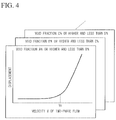
- the critical velocity analyzing section 28 plots a relationship between the displacement of the vibration pipe 3A and the velocity of the two-phase flow F corresponding to each other, and it finds a critical velocity Vc based on the correlative relationship therebetween.
- the critical velocity analyzing section 28 is capable of finding a critical velocity Vc for each void fraction segment, by plotting, for the input of each void fraction segment of the two-phase flow F, the relationship between the displacement of the vibration pipe 3A and the velocity V of the two-phase flow F.
- the void fraction analyzing section 13 in the void fraction measuring device 6, the local velocity analyzing section 19 in the local velocity measuring device 20, the velocity calculation section 27 in the two-phase flow velocity measuring device 7, and the critical velocity analyzing section 28, are integrally configured as an analyzing device 30.
- a two-phase flow F taken as a model flow is flowed in the flow section 2, and the vibration pipe 3A, which is one of the tube bodies 3 arranged so as to intersect with the flow of the two-phase flow F, is vibrated by the shaking device 4.
- the vibration pipe 3A is excited by an exciting force which acts from the two-phase flow F flowing therearound.
- the displacement associated with the vibration of the vibration pipe 3A is measured by the exciting force evaluation device 5, and the void fraction measuring device 6 measures the void fraction of the two-phase flow F which is flowing in the vicinity at this time.
- a local velocity V1 is measured by the local velocity measuring device 20.
- the velocity V of the two-phase flow F supplied into the flow section 2 is measured by the two-phase flow F measuring device.
- the critical velocity analyzing section 28 finds a critical velocity Vc for each void fraction segment.
- the void fraction of the two-phase flow F and the exciting force acting on the tube body 3 can both be integrally measured without having to measure them respectively with independent equipment, by conducting the measurement with use of the vibration pipe 3A formed from a conductive metallic material. Therefore, installation of the device can be easily performed with a minimum number of members and a simple configuration, without making the entire device large, and an exciting force and a void fraction can be associated with each other and can be accurately measured. As a result, it is possible, with a simple configuration, to easily and accurately evaluate the exciting force which acts on the tube body 3 from the two-phase flow F.
- the local velocity measuring device 20 also correspondingly finds the local velocity V1 of the two-phase flow F flowing in the vicinity of the vibration pipe 3A, and it is thereby possible to also evaluate the relationship between the local velocity V1 and the exciting force.
- FIG. 5 shows the second embodiment of the present invention.
- members which are commonly used in the embodiment described above are given the same reference symbols, and descriptions thereof are omitted.
- a void fraction measuring device 41 has; a first voltage measuring section 43 that measures a potential difference between first electrodes 42 provided on the inner surface of the flow section 2 facing the vibration pipe 3A and the surface of the vibration pipe 3A, and a void fraction analyzing section 13 that calculates a void fraction based on the potential difference detected by the first voltage measuring section 43.
- the potential difference between the first electrodes 42 and the vibration pipe 3A changes according to the void fraction of the two-phase flow F flowing between the first electrodes 42 and the vibration pipe 3A. Therefore it is possible, in the void fraction analyzing section 13, to calculate and find a void fraction based on the potential difference measured by the first voltage measuring section 43. As a result, also in the present embodiment, it is possible, with a simple configuration, to easily and accurately evaluate the exciting force acting from the two-phase flow on the vibration pipe 3A, based on this void fraction, using the vibration pipe 3A, which is formed from a conductive metallic material.
- the exciting force evaluation device 5 displacement of the vibration pipe 3A is measured using the displacement sensor 5a, and the exciting force is evaluated according to this displacement.
- a stress sensor may be provided on the vibration pipe 3A, and the exciting force may be evaluated according to the stress detected by this stress sensor.
- the vibration pipe 3A which is vibrated and displaced by the exciting force, the stress also changes according to the displacement, and accordingly, the exciting force can also be evaluated by extracting the amplitude of the stress waveform.
- the vibration pipe 3A is formed from a conductive metallic material. However, it is sufficient that the surface of the vibration pipe 3A is at least partially formed from an electrically conductive metallic material.
- evaluation of the exciting force of the two-phase flow is described to be conducted with use the two-phase flow exciting force evaluation device 1 or 40, however, it is not limited to this.
- evaluating the exciting force of the two-phase flow it is sufficient if there is provided a configuration in which; at least one of the plurality of tube bodies 3 is vibrated by the shaking device 4 to measure the displacement or stress of the tube body corresponding to the exciting force acting on the tube body which is vibrating, and a potential difference between the electric potential at a predetermined position on the surface of the tube body 3 and a reference electric potential can be measured.
Landscapes
- Physics & Mathematics (AREA)
- Engineering & Computer Science (AREA)
- Plasma & Fusion (AREA)
- General Engineering & Computer Science (AREA)
- High Energy & Nuclear Physics (AREA)
- Acoustics & Sound (AREA)
- Health & Medical Sciences (AREA)
- Life Sciences & Earth Sciences (AREA)
- Chemical & Material Sciences (AREA)
- Analytical Chemistry (AREA)
- Biochemistry (AREA)
- General Health & Medical Sciences (AREA)
- General Physics & Mathematics (AREA)
- Immunology (AREA)
- Pathology (AREA)
- Measuring Volume Flow (AREA)
- Measurement Of Mechanical Vibrations Or Ultrasonic Waves (AREA)
- Monitoring And Testing Of Nuclear Reactors (AREA)
- Investigating Or Analyzing Materials By The Use Of Electric Means (AREA)
Claims (11)
- Verfahren zur Bestimmung der Anregungskraft einer Zweiphasenströmung, die von einer einen Strömungsabschnitt (2) durchfließenden Zweiphasenströmung (F) auf eine Vielzahl von Rohrkörpern (3) ausgeübt wird, die derart angeordnet sind, dass sie den Strom der Zweiphasenströmung (F) schneiden, umfassend:Ausbilden der Oberfläche eines der Vielzahl von Rohrkörpern (3) mindestens teilweise aus elektrisch leitendem Werkstoff,Messen von Verschiebung des Rohrkörpers (3) oder mechanischer Spannung im Rohrkörper (3) in einem von einem Rüttler (4) bewirkten Vibrationszustand mit gewünschter Amplitude und Frequenz, der die Vibration simuliert, die von der den Rohrkörper durchfließenden Fluidströmung erzeugt wird, und Messen des Gasgehalts der Zweiphasenströmung (F), die in der Umgebung des Rohrkörpers (3) fließt, aufgrund der Potentialdifferenz zwischen einem elektrischen Potential an einer festgelegten Stelle an der Oberfläche des Rohrkörpers (3) und einem elektrischen Bezugspotential.
- Verfahren zur Bestimmung der Anregungskraft einer Zweiphasenströmung nach Patentanspruch 1, außerdem umfassend:Messen der Geschwindigkeit der Zweiphasenströmung (F), und Bestimmen der kritischen Geschwindigkeit (Vc) für jeden Gasgehalt aus dem gemessenen Gasgehalt und der Geschwindigkeit der Zweiphasenströmung (F) und der Verschiebung des Rohrkörpers (3) oder der mechanischen Spannung im Rohrkörper (3).
- Verfahren zur Bestimmung der Anregungskraft einer Zweiphasenströmung nach einem der Patentansprüche 1 und 2, in dem der Gasgehalt der Zweiphasenströmung (F) durch Messung einer Potentialdifferenz zwischen zwei Punkten an der Oberfläche des Rohrkörpers (3) bestimmt wird.
- Verfahren zur Bestimmung der Anregungskraft einer Zweiphasenströmung nach Patentanspruch 3, in dem
außerdem an der Oberfläche des Rohrkörpers (3) eine Potentialdifferenz zwischen weiteren zwei Punkten an anderen Stellen in Strömungsrichtung der Zweiphasenströmung (F) gemessen wird, sowie
eine lokale Geschwindigkeit der Zweiphasenströmung (F), die in der Umgebung des Rohrkörpers (3) fließt, aus der Phasendifferenz von Wellenformen der Potentialdifferenz, die jeweils an beiden Punkten gemessen wird, bestimmt wird. - Verfahren zur Bestimmung der Anregungskraft einer Zweiphasenströmung nach Patentanspruch 1, in dem
der Gasgehalt der Zweiphasenströmung (F) durch Messung der Potentialdifferenz zwischen der Oberfläche des Rohrkörpers (3) und der Innenfläche des Strömungsabschnitts (2) bestimmt wird. - Vorrichtung (1) zur Bestimmung der Anregungskraft einer Zweiphasenströmung, die von einer einen Strömungsabschnitt (2) durchfließenden Zweiphasenströmung (F) auf eine Vielzahl von Rohrkörpern (3) ausgeübt wird, die derart angeordnet sind, dass den Strom der Zweiphasenströmung (F) schneiden, umfassend:ein Vibrationsrohr (3A) als eines der Vielzahl von Rohrkörpern (3), dessen Oberfläche mindestens teilweise aus elektrisch leitendem Werkstoff ausgebildet ist,einen Rüttler (4), dafür eingerichtet, das Vibrationsrohr (3A) in Vibration mit gewünschter Amplitude und Frequenz zu versetzen, die die Vibration simuliert, die von der den Rohrkörper durchfließenden Fluidströmung erzeugt wird,eine Vorrichtung (5), die die Verschiebung des Vibrationsrohres (3A) oder mechanische Spannung im Vibrationsrohr (3A) misst, undeine Vorrichtung (6) zum Messen des Gasgehalts der Zweiphasenströmung (F), die in der Umgebung des Vibrationsrohres (3A) fließt, aufgrund der Potentialdifferenz zwischen einem elektrischen Potential an einer festgelegten Stelle an der Oberfläche des Vibrationsrohres (3A) und einem elektrischen Bezugspotential.
- Vorrichtung (1) zur Bestimmung der Anregungskraft einer Zweiphasenströmung nach Patentanspruch 6, in der eine Vorrichtung (7) zum Messen der Geschwindigkeit der Zweiphasenströmung vorgesehen wird, die die Geschwindigkeit der Zweiphasenströmung (F) misst,
- Vorrichtung (1) zur Bestimmung der Anregungskraft einer Zweiphasenströmung nach Patentanspruch 7, in der eine Einheit (28) zur Untersuchung der kritischen Geschwindigkeit vorgesehen ist, die die kritische Geschwindigkeit (Vc) für jeden Gasgehalt aus der Geschwindigkeit der Zweiphasenströmung (F), die von der Vorrichtung (7) zum Messen der Geschwindigkeit der Zweiphasenströmung gemessen wird, dem Gasgehalt der Zweiphasenströmung (F), der von der Vorrichtung (6) zum Messen des Gasgehalts gemessen wird, und der Verschiebung des Vibrationsrohres (3A) oder der mechanischen Spannung im Vibrationsrohr (3A), die von der Vorrichtung (5) zur Bestimmung der Anregungskraft gemessen wird, bestimmt.
- Vorrichtung (1) zur Bestimmung der Anregungskraft einer Zweiphasenströmung nach irgendeinem der Patentansprüche 6 bis 8, in der die Vorrichtung (6) zum Messen des Gasgehalts über
ein Paar erster Elektroden (10, 11) verfügt, die mit Abstand voneinander an der Oberfläche des Vibrationsrohres (3A) vorgesehen sind,
eine erste Spannungsmesseinheit (12), die eine Potentialdifferenz zwischen den ersten Elektroden (10, 11) bestimmt, und
eine Einheit zur Untersuchung des Gasgehalts (13), die den Gasgehalt aus der Potentialdifferenz berechnet, die von der ersten Spannungsmesseinheit (12) bestimmt wurde. - Vorrichtung (1) zur Bestimmung der Anregungskraft einer Zweiphasenströmung nach Patentanspruch 9, in der an der Oberfläche des Vibrationsrohres (3A) an anderer Stelle als der des Paars der ersten Elektroden (10, 11), in Strömungsrichtung der Zweiphasenströmung (F) ein Paar zweiter Elektroden (16, 17) mit Abstand voneinander vorgesehen ist,
und eine Vorrichtung (20) zur Messung der lokalen Geschwindigkeit, die umfasst:das Paar erster Elektroden (10, 11),die erste Spannungsmesseinheit (12),das Paar zweiter Elektroden (16, 17),eine zweite Spannungsmesseinheit (18), die die Potentialdifferenz zwischen den zweiten Elektroden (16, 17) bestimmt, undeine Einheit zur Untersuchung der lokalen Geschwindigkeit (19), die eine lokale Geschwindigkeit der Zweiphasenströmung (F), die in der Umgebung des Vibrationsrohres (3A) fließt, aus der Phasendifferenz der Wellenform der Potentialdifferenz, die von der ersten Spannungsmesseinheit (12) gemessen wird, und der Phasendifferenz der Wellenform der Potentialdifferenz, die von der zweiten Spannungsmesseinheit (18) gemessen wird, bestimmt. - Vorrichtung (1) zur Bestimmung der Anregungskraft einer Zweiphasenströmung nach Patentanspruch 6, in der die Vorrichtung (41) zur Messung des Gasgehalts verfügt über:eine Elektrode (42), die an der Innenfläche des Strömungsabschnittes (2) derart vorgesehen ist, dass sie der Oberfläche des Vibrationsrohres (3A) zugewandt ist,eine Spannungsmesseinheit (43), die die Potentialdifferenz zwischen dem Vibrationsrohr (3A) und der Elektrode (42) bestimmt, undeine Einheit (13) zur Messung des Gasgehalts, die den Gasgehalt aus der Potentialdifferenz berechnet, die von der Spannungsmesseinheit (43) bestimmt wird.
Applications Claiming Priority (2)
| Application Number | Priority Date | Filing Date | Title |
|---|---|---|---|
| JP2009121190A JP2010271074A (ja) | 2009-05-19 | 2009-05-19 | 二相流励振力評価方法及び二相流励振力評価装置 |
| PCT/JP2009/006990 WO2010134148A1 (ja) | 2009-05-19 | 2009-12-17 | 二相流励振力評価方法及び二相流励振力評価装置 |
Publications (3)
| Publication Number | Publication Date |
|---|---|
| EP2434498A1 EP2434498A1 (de) | 2012-03-28 |
| EP2434498A4 EP2434498A4 (de) | 2015-04-01 |
| EP2434498B1 true EP2434498B1 (de) | 2016-03-30 |
Family
ID=43125847
Family Applications (1)
| Application Number | Title | Priority Date | Filing Date |
|---|---|---|---|
| EP09844882.2A Active EP2434498B1 (de) | 2009-05-19 | 2009-12-17 | Verfahren und vorrichtung zur beurteilung der erregerkraft einer zweiphasen-strömung |
Country Status (5)
| Country | Link |
|---|---|
| US (1) | US8707801B2 (de) |
| EP (1) | EP2434498B1 (de) |
| JP (1) | JP2010271074A (de) |
| KR (1) | KR101314389B1 (de) |
| WO (1) | WO2010134148A1 (de) |
Families Citing this family (2)
| Publication number | Priority date | Publication date | Assignee | Title |
|---|---|---|---|---|
| JP6307291B2 (ja) * | 2013-02-06 | 2018-04-04 | 三菱重工業株式会社 | 物理量の計測システム及び解析モデルの構築方法 |
| CN105651486B (zh) * | 2016-03-18 | 2017-11-17 | 浙江大学 | 流体诱发换热器管束振动试验测试系统 |
Family Cites Families (8)
| Publication number | Priority date | Publication date | Assignee | Title |
|---|---|---|---|---|
| JPS5849899A (ja) * | 1981-09-18 | 1983-03-24 | Matsushita Electric Ind Co Ltd | 熱交換器の安全装置 |
| JPS5926373A (ja) * | 1982-08-05 | 1984-02-10 | Nissan Motor Co Ltd | 自動車用スペアタイヤカバ− |
| JPS6256825A (ja) | 1985-09-06 | 1987-03-12 | Hitachi Ltd | 管群等の異常振動診断方法および装置 |
| JPS62106336A (ja) * | 1985-11-05 | 1987-05-16 | Toshiba Corp | 蒸気発生器 |
| JPH0546883A (ja) | 1991-08-21 | 1993-02-26 | Toshiba Corp | 監視データ出力方式 |
| JP2001272494A (ja) | 2000-03-23 | 2001-10-05 | Japan Atom Energy Res Inst | 気液2相からなる流路内のボイド率を瞬時に計測する方法。 |
| JP2007033062A (ja) | 2005-07-22 | 2007-02-08 | Japan Atomic Energy Agency | 高温高圧で複雑な流路内のボイド率を瞬時計測する電気式ボイド率計及びボイド率計測法 |
| JP5017724B2 (ja) | 2007-11-16 | 2012-09-05 | 高周波熱錬株式会社 | 鋼材 |
-
2009
- 2009-05-19 JP JP2009121190A patent/JP2010271074A/ja not_active Withdrawn
- 2009-12-17 EP EP09844882.2A patent/EP2434498B1/de active Active
- 2009-12-17 KR KR1020117012797A patent/KR101314389B1/ko active Active
- 2009-12-17 US US13/133,807 patent/US8707801B2/en active Active
- 2009-12-17 WO PCT/JP2009/006990 patent/WO2010134148A1/ja not_active Ceased
Also Published As
| Publication number | Publication date |
|---|---|
| EP2434498A1 (de) | 2012-03-28 |
| WO2010134148A1 (ja) | 2010-11-25 |
| KR20110081348A (ko) | 2011-07-13 |
| EP2434498A4 (de) | 2015-04-01 |
| US8707801B2 (en) | 2014-04-29 |
| JP2010271074A (ja) | 2010-12-02 |
| US20110239779A1 (en) | 2011-10-06 |
| KR101314389B1 (ko) | 2013-10-04 |
Similar Documents
| Publication | Publication Date | Title |
|---|---|---|
| US20100011882A1 (en) | Method for operating a vibratory measuring instrument, and corresponding instrument | |
| RU2606345C2 (ru) | Расходомер | |
| CA2833329C (en) | Nuclear magnetic flow meter and method for operation of nuclear magnetic flow meters | |
| JP4796144B2 (ja) | 送電線を通る電力流を監視する方法及びシステム | |
| US20190383657A1 (en) | Mass flow meter according to the coriolis principle and method for determining a mass flow | |
| EP2860537B1 (de) | Elektrische leckdetektionsvorrichtung | |
| US9207212B2 (en) | Method for operating a resonant measurement system | |
| JP2012242358A (ja) | 渦流探傷装置 | |
| Chandrasekharan et al. | A microscale differential capacitive direct wall-shear-stress sensor | |
| JP2012047706A (ja) | 電磁流量計測システム及びその校正装置 | |
| EP2434498B1 (de) | Verfahren und vorrichtung zur beurteilung der erregerkraft einer zweiphasen-strömung | |
| US11326919B2 (en) | Coriolis mass flow meter having a central vibration sensor and method for determining the viscosity of the medium using Coriolis mass flow meter | |
| JP6827569B2 (ja) | 相互変調歪み信号干渉を防止するための周波数間隔 | |
| US20220299355A1 (en) | Coriolis measuring sensor and coriolis measuring device | |
| CN104949722A (zh) | 磁感应流量测量仪和用于运行磁感应流量测量仪的方法 | |
| CN105258741B (zh) | 流量计、绝缘劣化诊断系统以及绝缘劣化诊断方法 | |
| US9121878B2 (en) | Method for contactless determination of electrical potential using oscillating electrode, and device | |
| US12540840B2 (en) | Electromagnetic flowmeter with a plurality of coils | |
| US20230384134A1 (en) | Coriolis flowmeter and method for operating the coriolis flowmeter | |
| JP3113946B2 (ja) | 渦流量計 | |
| EP3638990B1 (de) | Minimierung eines wellenkamms eines mehrtonansteuerungssignals in einem vibrationsmesser | |
| JP6124572B2 (ja) | 渦流量計 | |
| US20210310842A1 (en) | Coil apparatus of an oscillation sensor or of an oscillation exciter, measuring transducer and measuring instrument | |
| Grossman et al. | Turbulence in civil engineering: Investigations in liquid shear flow by electromagnetic induction | |
| RU172140U1 (ru) | Вихревый электромагнитный преобразователь расхода жидкости |
Legal Events
| Date | Code | Title | Description |
|---|---|---|---|
| PUAI | Public reference made under article 153(3) epc to a published international application that has entered the european phase |
Free format text: ORIGINAL CODE: 0009012 |
|
| 17P | Request for examination filed |
Effective date: 20110616 |
|
| AK | Designated contracting states |
Kind code of ref document: A1 Designated state(s): AT BE BG CH CY CZ DE DK EE ES FI FR GB GR HR HU IE IS IT LI LT LU LV MC MK MT NL NO PL PT RO SE SI SK SM TR |
|
| DAX | Request for extension of the european patent (deleted) | ||
| A4 | Supplementary search report drawn up and despatched |
Effective date: 20150227 |
|
| RIC1 | Information provided on ipc code assigned before grant |
Ipc: G21C 17/003 20060101AFI20150223BHEP |
|
| REG | Reference to a national code |
Ref country code: DE Ref legal event code: R079 Ref document number: 602009037433 Country of ref document: DE Free format text: PREVIOUS MAIN CLASS: G21C0017003000 Ipc: G01N0029032000 |
|
| GRAP | Despatch of communication of intention to grant a patent |
Free format text: ORIGINAL CODE: EPIDOSNIGR1 |
|
| RIC1 | Information provided on ipc code assigned before grant |
Ipc: G01N 29/032 20060101AFI20150915BHEP Ipc: G21D 1/00 20060101ALI20150915BHEP Ipc: G21C 17/017 20060101ALI20150915BHEP Ipc: G01N 29/04 20060101ALI20150915BHEP Ipc: G21C 17/022 20060101ALI20150915BHEP Ipc: G21C 17/10 20060101ALI20150915BHEP |
|
| INTG | Intention to grant announced |
Effective date: 20151006 |
|
| GRAS | Grant fee paid |
Free format text: ORIGINAL CODE: EPIDOSNIGR3 |
|
| GRAA | (expected) grant |
Free format text: ORIGINAL CODE: 0009210 |
|
| AK | Designated contracting states |
Kind code of ref document: B1 Designated state(s): AT BE BG CH CY CZ DE DK EE ES FI FR GB GR HR HU IE IS IT LI LT LU LV MC MK MT NL NO PL PT RO SE SI SK SM TR |
|
| REG | Reference to a national code |
Ref country code: GB Ref legal event code: FG4D |
|
| REG | Reference to a national code |
Ref country code: CH Ref legal event code: EP |
|
| REG | Reference to a national code |
Ref country code: AT Ref legal event code: REF Ref document number: 785922 Country of ref document: AT Kind code of ref document: T Effective date: 20160415 |
|
| REG | Reference to a national code |
Ref country code: IE Ref legal event code: FG4D |
|
| REG | Reference to a national code |
Ref country code: DE Ref legal event code: R096 Ref document number: 602009037433 Country of ref document: DE |
|
| REG | Reference to a national code |
Ref country code: LT Ref legal event code: MG4D |
|
| PG25 | Lapsed in a contracting state [announced via postgrant information from national office to epo] |
Ref country code: GR Free format text: LAPSE BECAUSE OF FAILURE TO SUBMIT A TRANSLATION OF THE DESCRIPTION OR TO PAY THE FEE WITHIN THE PRESCRIBED TIME-LIMIT Effective date: 20160701 Ref country code: HR Free format text: LAPSE BECAUSE OF FAILURE TO SUBMIT A TRANSLATION OF THE DESCRIPTION OR TO PAY THE FEE WITHIN THE PRESCRIBED TIME-LIMIT Effective date: 20160330 Ref country code: FI Free format text: LAPSE BECAUSE OF FAILURE TO SUBMIT A TRANSLATION OF THE DESCRIPTION OR TO PAY THE FEE WITHIN THE PRESCRIBED TIME-LIMIT Effective date: 20160330 Ref country code: NO Free format text: LAPSE BECAUSE OF FAILURE TO SUBMIT A TRANSLATION OF THE DESCRIPTION OR TO PAY THE FEE WITHIN THE PRESCRIBED TIME-LIMIT Effective date: 20160630 |
|
| REG | Reference to a national code |
Ref country code: NL Ref legal event code: MP Effective date: 20160330 |
|
| REG | Reference to a national code |
Ref country code: AT Ref legal event code: MK05 Ref document number: 785922 Country of ref document: AT Kind code of ref document: T Effective date: 20160330 |
|
| PG25 | Lapsed in a contracting state [announced via postgrant information from national office to epo] |
Ref country code: LV Free format text: LAPSE BECAUSE OF FAILURE TO SUBMIT A TRANSLATION OF THE DESCRIPTION OR TO PAY THE FEE WITHIN THE PRESCRIBED TIME-LIMIT Effective date: 20160330 Ref country code: LT Free format text: LAPSE BECAUSE OF FAILURE TO SUBMIT A TRANSLATION OF THE DESCRIPTION OR TO PAY THE FEE WITHIN THE PRESCRIBED TIME-LIMIT Effective date: 20160330 Ref country code: SE Free format text: LAPSE BECAUSE OF FAILURE TO SUBMIT A TRANSLATION OF THE DESCRIPTION OR TO PAY THE FEE WITHIN THE PRESCRIBED TIME-LIMIT Effective date: 20160330 |
|
| PG25 | Lapsed in a contracting state [announced via postgrant information from national office to epo] |
Ref country code: NL Free format text: LAPSE BECAUSE OF FAILURE TO SUBMIT A TRANSLATION OF THE DESCRIPTION OR TO PAY THE FEE WITHIN THE PRESCRIBED TIME-LIMIT Effective date: 20160330 |
|
| PG25 | Lapsed in a contracting state [announced via postgrant information from national office to epo] |
Ref country code: EE Free format text: LAPSE BECAUSE OF FAILURE TO SUBMIT A TRANSLATION OF THE DESCRIPTION OR TO PAY THE FEE WITHIN THE PRESCRIBED TIME-LIMIT Effective date: 20160330 Ref country code: PL Free format text: LAPSE BECAUSE OF FAILURE TO SUBMIT A TRANSLATION OF THE DESCRIPTION OR TO PAY THE FEE WITHIN THE PRESCRIBED TIME-LIMIT Effective date: 20160330 Ref country code: IS Free format text: LAPSE BECAUSE OF FAILURE TO SUBMIT A TRANSLATION OF THE DESCRIPTION OR TO PAY THE FEE WITHIN THE PRESCRIBED TIME-LIMIT Effective date: 20160730 |
|
| REG | Reference to a national code |
Ref country code: FR Ref legal event code: PLFP Year of fee payment: 8 |
|
| PG25 | Lapsed in a contracting state [announced via postgrant information from national office to epo] |
Ref country code: PT Free format text: LAPSE BECAUSE OF FAILURE TO SUBMIT A TRANSLATION OF THE DESCRIPTION OR TO PAY THE FEE WITHIN THE PRESCRIBED TIME-LIMIT Effective date: 20160801 Ref country code: AT Free format text: LAPSE BECAUSE OF FAILURE TO SUBMIT A TRANSLATION OF THE DESCRIPTION OR TO PAY THE FEE WITHIN THE PRESCRIBED TIME-LIMIT Effective date: 20160330 Ref country code: SK Free format text: LAPSE BECAUSE OF FAILURE TO SUBMIT A TRANSLATION OF THE DESCRIPTION OR TO PAY THE FEE WITHIN THE PRESCRIBED TIME-LIMIT Effective date: 20160330 Ref country code: ES Free format text: LAPSE BECAUSE OF FAILURE TO SUBMIT A TRANSLATION OF THE DESCRIPTION OR TO PAY THE FEE WITHIN THE PRESCRIBED TIME-LIMIT Effective date: 20160330 Ref country code: SM Free format text: LAPSE BECAUSE OF FAILURE TO SUBMIT A TRANSLATION OF THE DESCRIPTION OR TO PAY THE FEE WITHIN THE PRESCRIBED TIME-LIMIT Effective date: 20160330 Ref country code: CZ Free format text: LAPSE BECAUSE OF FAILURE TO SUBMIT A TRANSLATION OF THE DESCRIPTION OR TO PAY THE FEE WITHIN THE PRESCRIBED TIME-LIMIT Effective date: 20160330 Ref country code: RO Free format text: LAPSE BECAUSE OF FAILURE TO SUBMIT A TRANSLATION OF THE DESCRIPTION OR TO PAY THE FEE WITHIN THE PRESCRIBED TIME-LIMIT Effective date: 20160330 |
|
| PG25 | Lapsed in a contracting state [announced via postgrant information from national office to epo] |
Ref country code: IT Free format text: LAPSE BECAUSE OF FAILURE TO SUBMIT A TRANSLATION OF THE DESCRIPTION OR TO PAY THE FEE WITHIN THE PRESCRIBED TIME-LIMIT Effective date: 20160330 Ref country code: BE Free format text: LAPSE BECAUSE OF FAILURE TO SUBMIT A TRANSLATION OF THE DESCRIPTION OR TO PAY THE FEE WITHIN THE PRESCRIBED TIME-LIMIT Effective date: 20160330 |
|
| REG | Reference to a national code |
Ref country code: DE Ref legal event code: R097 Ref document number: 602009037433 Country of ref document: DE |
|
| PG25 | Lapsed in a contracting state [announced via postgrant information from national office to epo] |
Ref country code: DK Free format text: LAPSE BECAUSE OF FAILURE TO SUBMIT A TRANSLATION OF THE DESCRIPTION OR TO PAY THE FEE WITHIN THE PRESCRIBED TIME-LIMIT Effective date: 20160330 |
|
| PLBE | No opposition filed within time limit |
Free format text: ORIGINAL CODE: 0009261 |
|
| STAA | Information on the status of an ep patent application or granted ep patent |
Free format text: STATUS: NO OPPOSITION FILED WITHIN TIME LIMIT |
|
| 26N | No opposition filed |
Effective date: 20170103 |
|
| PG25 | Lapsed in a contracting state [announced via postgrant information from national office to epo] |
Ref country code: SI Free format text: LAPSE BECAUSE OF FAILURE TO SUBMIT A TRANSLATION OF THE DESCRIPTION OR TO PAY THE FEE WITHIN THE PRESCRIBED TIME-LIMIT Effective date: 20160330 |
|
| REG | Reference to a national code |
Ref country code: DE Ref legal event code: R119 Ref document number: 602009037433 Country of ref document: DE |
|
| REG | Reference to a national code |
Ref country code: CH Ref legal event code: PL |
|
| GBPC | Gb: european patent ceased through non-payment of renewal fee |
Effective date: 20161217 |
|
| PG25 | Lapsed in a contracting state [announced via postgrant information from national office to epo] |
Ref country code: MC Free format text: LAPSE BECAUSE OF FAILURE TO SUBMIT A TRANSLATION OF THE DESCRIPTION OR TO PAY THE FEE WITHIN THE PRESCRIBED TIME-LIMIT Effective date: 20160330 |
|
| REG | Reference to a national code |
Ref country code: IE Ref legal event code: MM4A |
|
| PG25 | Lapsed in a contracting state [announced via postgrant information from national office to epo] |
Ref country code: CH Free format text: LAPSE BECAUSE OF NON-PAYMENT OF DUE FEES Effective date: 20161231 Ref country code: LI Free format text: LAPSE BECAUSE OF NON-PAYMENT OF DUE FEES Effective date: 20161231 Ref country code: LU Free format text: LAPSE BECAUSE OF NON-PAYMENT OF DUE FEES Effective date: 20161217 |
|
| REG | Reference to a national code |
Ref country code: FR Ref legal event code: PLFP Year of fee payment: 9 |
|
| PG25 | Lapsed in a contracting state [announced via postgrant information from national office to epo] |
Ref country code: GB Free format text: LAPSE BECAUSE OF NON-PAYMENT OF DUE FEES Effective date: 20161217 Ref country code: IE Free format text: LAPSE BECAUSE OF NON-PAYMENT OF DUE FEES Effective date: 20161217 Ref country code: DE Free format text: LAPSE BECAUSE OF NON-PAYMENT OF DUE FEES Effective date: 20170701 |
|
| PG25 | Lapsed in a contracting state [announced via postgrant information from national office to epo] |
Ref country code: CY Free format text: LAPSE BECAUSE OF FAILURE TO SUBMIT A TRANSLATION OF THE DESCRIPTION OR TO PAY THE FEE WITHIN THE PRESCRIBED TIME-LIMIT Effective date: 20160330 Ref country code: HU Free format text: LAPSE BECAUSE OF FAILURE TO SUBMIT A TRANSLATION OF THE DESCRIPTION OR TO PAY THE FEE WITHIN THE PRESCRIBED TIME-LIMIT; INVALID AB INITIO Effective date: 20091217 |
|
| PG25 | Lapsed in a contracting state [announced via postgrant information from national office to epo] |
Ref country code: TR Free format text: LAPSE BECAUSE OF FAILURE TO SUBMIT A TRANSLATION OF THE DESCRIPTION OR TO PAY THE FEE WITHIN THE PRESCRIBED TIME-LIMIT Effective date: 20160330 Ref country code: MK Free format text: LAPSE BECAUSE OF FAILURE TO SUBMIT A TRANSLATION OF THE DESCRIPTION OR TO PAY THE FEE WITHIN THE PRESCRIBED TIME-LIMIT Effective date: 20160330 |
|
| PG25 | Lapsed in a contracting state [announced via postgrant information from national office to epo] |
Ref country code: BG Free format text: LAPSE BECAUSE OF FAILURE TO SUBMIT A TRANSLATION OF THE DESCRIPTION OR TO PAY THE FEE WITHIN THE PRESCRIBED TIME-LIMIT Effective date: 20160330 |
|
| PG25 | Lapsed in a contracting state [announced via postgrant information from national office to epo] |
Ref country code: MT Free format text: LAPSE BECAUSE OF NON-PAYMENT OF DUE FEES Effective date: 20161217 |
|
| P01 | Opt-out of the competence of the unified patent court (upc) registered |
Effective date: 20230522 |
|
| PGFP | Annual fee paid to national office [announced via postgrant information from national office to epo] |
Ref country code: FR Payment date: 20251110 Year of fee payment: 17 |