EP2434075B1 - Zaun zur Verwendung als Absperrzaun - Google Patents
Zaun zur Verwendung als Absperrzaun Download PDFInfo
- Publication number
- EP2434075B1 EP2434075B1 EP11182340.7A EP11182340A EP2434075B1 EP 2434075 B1 EP2434075 B1 EP 2434075B1 EP 11182340 A EP11182340 A EP 11182340A EP 2434075 B1 EP2434075 B1 EP 2434075B1
- Authority
- EP
- European Patent Office
- Prior art keywords
- fence
- blocking element
- crossbeam
- crossbeams
- post
- Prior art date
- Legal status (The legal status is an assumption and is not a legal conclusion. Google has not performed a legal analysis and makes no representation as to the accuracy of the status listed.)
- Active
Links
Images

Classifications
-
- E—FIXED CONSTRUCTIONS
- E04—BUILDING
- E04H—BUILDINGS OR LIKE STRUCTURES FOR PARTICULAR PURPOSES; SWIMMING OR SPLASH BATHS OR POOLS; MASTS; FENCING; TENTS OR CANOPIES, IN GENERAL
- E04H17/00—Fencing, e.g. fences, enclosures, corrals
- E04H17/14—Fences constructed of rigid elements, e.g. with additional wire fillings or with posts
- E04H17/1413—Post-and-rail fences, e.g. without vertical cross-members
- E04H17/1447—Details of connections between rails and posts
- E04H17/1465—Details of connections between rails and posts the rails being supported within blind or through holes of the posts
- E04H17/1469—Snap connections
Definitions
- This invention relates to a fence comprising at least two hollow fence panels, between which at least two crossbeams extend, wherein each crossbeam fits into an opening provided in the fence post, and a blocking element extending into the cavity of the fence post which is provided to block the crossbeams against displacement.
- This invention relates more particularly to a fence which has been designed specifically with the aim of offering an appropriate and economical solution as a barrier installation and/or screen and/or fall protection for a wide range of applications, both industrial and civil.
- a fence in the form of posts or barriers is set up temporarily or permanently in many companies at various locations with the aim of preventing machinery, objects and the like from being damaged by vehicles or means of transport during manoeuvring.
- a fence of this type can also be used as a screen to protect persons, for example to prevent them from falling downwards.
- a multiplicity of fences have already been developed, wherein rigid crossbeams are connected via a welded connection to a number of vertically disposed posts.
- a construction of this type has the disadvantage that the positioning thereof requires a lot of time and, furthermore, it is subsequently difficult to move and repair.
- the European patent publication EP 1 483 160 describes a fence with interlockable components, comprising a number of upright posts, between which a crossbeam made from a tubular plastic material extends, and which fits into a first opening provided in an upright post. The end of the crossbeam is provided with a second opening which lies within the hollow inner area of the vertical post.
- the fence described in EP 1 483 160 comprises a blocking element similarly made from a tubular plastic material.
- the tubular blocking element is forced into the aforementioned second opening, which is too small in relation to the tubular blocking element.
- the material of the blocking element will be slightly compressed during the positioning thereof, at the second opening. This compression will become permanent through time, as a result of which, as it were, a slight protuberance is formed on each side of the second opening, and as a result of which the tubular blocking element is, as it were, held mechanically in position.
- this has the disadvantage that the construction is subsequently difficult to dismantle.
- the tubular blocking element forms an obstacle to any present wiring which extends through the different crossbeams.
- the American patent publication US 3,921,960 describes a fence comprising all of the features of the preamble of claim 1. That is to say said fence comprises at least two hollow fence posts, between which at least two crossbeams extend.
- the fence comprises a plate-shaped blocking element which is provided to block the crossbeams against displacement, and which is movable between a first position in which the crossbeams are movable into and out of the fence post and a second position in which the crossbeams are blocked in place.
- the fence described in US 3,921,960 has the disadvantage that, on impact (for example due to a collision), the risk exists that only the blocking element will break, and, for example, only at one or more blocking positions (at the opening(s) in the blocking element).
- the damage is not visible, so that the risk exists that the broken blocking element will not be replaced, as a result of which the crossbeam sits, as it were, loosely in the fence post.
- the crossbeam thereby loses its function and, on a following impact, will immediately come loose from the fence post, with all associated risks.
- the object of this invention is now to provide a reliable fence which retains its specific function, even following an impact.
- An additional object is to provide a fence which can be simply and quickly assembled in situ, and which furthermore can subsequently be simply dismantled.
- the object of the invention is achieved by providing a fence comprising at least two hollow fence posts, between which at least two crossbeams extend, wherein each crossbeam fits into an opening provided in the fence post, a plate-shaped blocking element extending into the cavity of the fence post which is provided to block the crossbeams against displacement, wherein the crossbeams are provided in their external circumference with at least one recess which lies within the hollow inner area of the fence post and wherein the plate-shaped blocking element is movable between a first position in which the crossbeams are movable into and out of the fence post and a second position in which the crossbeams are blocked in place, wherein the aforementioned blocking element comprises at least two openings positioned at a distance from one another, which are each provided to block a crossbeam against displacement, and wherein the aforementioned blocking element is provided between the aforementioned openings with one or more break lines, along which the blocking element is breakable into different separate blocking elements.
- break lines of this type will ensure that the blocking element will break at the disposed break lines into separate blocking elements, which will each still perform their function, i.e. the blocking of the relevant crossbeam. In this way, breaking of the blocking element at other places, for example at the blocking position, is avoided. Consequently, the presence of break lines of this type will provide a more reliable fence. Furthermore, a fence of this type is very quick to install and can subsequently be easily dismantled, since the blocking element, which ensures the interlocking between the fence post and the crossbeam, is easily movable between the first and second position. Given that the recesses are located on the outer circumference of the crossbeam, this fence has the advantage that the blocking element no longer forms an obstacle to any cabling or other elements (for example strengthening rods) which extend through the different crossbeams.
- the aforementioned break lines must be regarded as a zone (a so-called break zone), which extends over virtually the entire width of the blocking element and is more breakable than the remainder of the blocking element.
- This can be achieved, for example, by designing the blocking element at the break zone as thinner than the remainder of the blocking element, or, for example, by making the break zone from a suitable material which breaks more easily than the material from which the remainder of the blocking element is made. It is evident that other solutions for providing a weaker zone in the blocking element similarly fall within the scope of protection of this invention.
- the crossbeam comprises two recesses located opposite one another which extend across the longitudinal direction of the crossbeam. Both recesses are preferably symmetrically structured.
- the fence posts are made from tubular plastic material, extending essentially vertically in the assembled condition of the fence
- the crossbeams are made from tubular plastic material, extending essentially horizontally in the assembled condition of the fence.
- These can be manufactured, for example, via injection moulding and/or extrusion.
- the openings provided in the blocking element have a width on their one side which is greater than the width of the crossbeam to be blocked and, on their opposite side, a width which is smaller than the width of the crossbeam to be blocked. More specifically, the opening is constructed from:
- the specific shape, more specifically key-shaped, of the opening disposed in the blocking element allows the crossbeam to be moved into and out of the fence post in a first position of the blocking element, and to be blocked in a second position.
- the fence comprises a plurality of crossbeams positioned above one another, the latter can be blocked with the same blocking element.
- the blocking element in a more particular embodiment of the fence, is provided with a first, second and third opening which are provided to block the first, second and third crossbeam respectively, wherein one or more break lines are provided between the first and second opening, and between the second and third opening. It is self-evident that, in the case of a fourth or possibly fifth crossbeam, the blocking element can further be provided with a fourth and fifth opening of a similar type.
- the blocking element comprises, in its outer circumference, at least one recess which is dimensioned in such a way that it is suitable to serve as a grip during the movement of the blocking element between the first and second position.
- the blocking element preferably comprises two recesses located opposite one another which are dimensioned in such a way that they are suitable to serve as a grip during the movement of the blocking element between the first and second position. Recesses of this type give the user of the fence the facility to grip the blocking element easily and firmly with the fingers of the hand in order to move it between the first and second position, or to insert it easily into the vertically disposed fence post and to push it over the one or more crossbeams or to easily remove the blocking element.
- the blocking element is made from plastic.
- the required shape thereof can be simply implemented, for example, via injection moulding.
- the fence post comprises at least one essentially flat rear side and front side and at least two essentially flat side surfaces, and, following attachment of the crossbeam to the fence post, the blocking element lies against one of the flat side surfaces.
- the blocking element in the assembled condition will exert a tension both sideways and from above on the inserted crossbeam i.e. if a horizontal or vertical force is exerted on the fence, the crossbeam is always clamped in place with two sides. In specific cases, even three sides will offer resistance.
- the fence post has a round cross-section and, following attachment of the crossbeam to the fence post, the blocking element lies against a curved side wall.
- the flat blocking plate will, as it were, be forced during the assembly to assume the shape of the fence post and as a result will be slightly curved. As a result, an additional tension will be created which will ensure that the fence becomes stronger.
- the fence post comprises a base plate in order to attach it to an underlying structure.
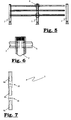
- a fence (1) according to this invention as shown, inter alia, in Figures 1 and 5 , comprises two or more fence posts (2), between which at least two crossbeams (3) extend.
- three crossbeams (3a;3b;3c) are provided in each case between vertically standing fence posts (2).
- the fence (1) according to this invention can be designed as a straight line, but it is also possible to design it as angular (see, for example Fig. 9 ).
- the fence posts (2) which are shown in Figures 1 , 5 and 8 , are hollow posts with a simple basic form, so that they can be simply produced. They comprise an essentially flat rear side, two essentially flat side areas and a flat front side. However, the fence posts may also have a round cross-section.
- the fence posts (2) may, for example, be made from an aluminium alloy, or from steel, or from plastic, etc., and may, for example, be manufactured via folding, or via welding, via injection moulding, or via extrusion, etc.
- These fence posts (2) are preferably manufactured from a tubular plastic material, and, in the assembled condition of the fence (1), will extend essentially vertically.
- the crossbeams (3) are also preferably made from tubular plastic material, and, in the assembled condition of the fence (2), will essentially extend horizontally.
- the fence (1) comprises at least two hollow fence posts (2), between which at least two crossbeams (3) extend, wherein each crossbeam (3) fits into a specific opening (4) provided in the fence post (2).
- the crossbeam (3) will extend partially into the hollow inner area of the fence post (2) after it has been inserted into the opening (4).
- the fence post (2) will comprise as many openings (4) as the number of crossbeams which must be assembled between two vertically positioned fence posts.
- the openings (4) are provided in the two side areas if the fence post (2) is used as an intermediate post (see, for example, Fig. 6 ), and are provided in one side area if the fence post (2) is used as an end post.
- a blocking element (5) is provided in the hollow inner area of the fence post (2).
- this blocking element (5) is preferably made from a plastic plate in which an opening (8) is provided.
- the blocking element (5) preferably has a thickness of between 2 and 25 mm.
- the plate-shaped blocking element (5) is movable between a first position in which the crossbeam (3) is movable into and out of the fence post (2) and a second position in which the crossbeam (3) is blocked in place.
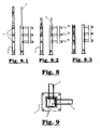
- the crossbeam (3) in order to block the crossbeam (3) by means of the blocking element (5) or allow it to move into and out of the fence post (2), the crossbeam (3), as shown in Figures 2 and 3 , comprises at least one recess (6a;6b) which, in the assembled condition, lies within the hollow inner area of the fence post (2), and wherein the blocking element (5) is movable.
- the crossbeam (3) preferably comprises two recesses (6a and 6b) located opposite one another, which extend across the longitudinal direction of the crossbeam (3).
- Such a way of connecting, wherein the described blocking element is used, furthermore allows the fence to be dismantled in a simple manner, simply by moving the blocking element (5) from the second to the first position.
- the blocking element (5) comprises an opening (8).
- the specific shape of the opening (8) allows the crossbeam (3) to be moved into and out of the fence post (2) in a first position of the blocking element (5), and to be blocked in a second position.
- the opening (8) On the one side of the blocking element, which, in the assembled condition, is the underside, the opening (8) has a width which is greater than the width of the crossbeam (3) to be blocked, and, on the opposite side (the upper side of the blocking element), has a width which is smaller than the width of the crossbeam (3) to be blocked. More specifically, the opening is constructed from:
- the blocking element (5) is provided with a number of openings (8) as described above.
- Three crossbeams (3a,3b,3c) can be blocked with the blocking element (5) shown in Figure 7 . This is shown in successive steps in Figures 8.1 to 8.3 .
- the blocking element (5) furthermore comprises so-called break lines (10) or break zones, as a result of which different blocking elements can be formed.
- the break lines (10) are preferably formed by disposing a weakening in the material from which the blocking element is formed, which can be done, for example, by designing the blocking element at this specific location as thinner than the remainder of the blocking element, or by using a different material which is more breakable than the material from which the remainder of the blocking element is formed.
- break lines of this type will ensure that, in the event of any impact, the blocking element will break at the disposed break lines into separate blocking elements, which will each still perform their function, i.e. the blocking of the relevant crossbeam. In this way, breaking of the blocking element at other places, for example at the blocking position, is avoided. Because a fence provided with a blocking element of this type which, even following an impact, provides for a continuing blocking of the crossbeams, a fence of this type will be much more reliable than the known fences.
- the three crossbeams (3a,3b,3c) are inserted into the openings (4) provided in the fence post (2).
- the blocking element (5) is then inserted into the hollow inner area of the fence post and is pushed over the part of the crossbeam (3) which is located in the hollow inner area of the fence post (2) (see Figure 8.2 ).
- the blocking element (5) is located in its first position and the part of the opening (8) with a width which is greater than the width of the crossbeam to be blocked is located at a crossbeam (3a,3b,3c) so that the blocking element can be pushed over the different crossbeams until the blocking element comes into contact with the recesses (6a,6b) disposed in the crossbeams. If the user releases the blocking element (5) at that moment, it will fall downwards under the influence of gravity and be located in its second position (see Fig. 8.3 ), in which the different crossbeams (3) are blocked in place.
- the blocking element (5) preferably comprises two recesses (7) located opposite one another which are dimensioned in such a way that they are suitable to serve as a grip during the movement of the blocking element (5) between the first and second position.
- the fence (1) according to this invention is preferably used as a barrier installation to protect persons, machinery, tools, goods and buildings where lift trucks or other traffic is present.
- the fence can also be used as a physical screen along a pit or on a gantry in order to thereby prevent persons from falling into the pit or from the gantry.
- the described fence furthermore requires a minimum of maintenance, has a long service life, can be simply installed, moved and dismantled, and is impact-resistant.
Landscapes
- Engineering & Computer Science (AREA)
- Architecture (AREA)
- Civil Engineering (AREA)
- Structural Engineering (AREA)
- Refuge Islands, Traffic Blockers, Or Guard Fence (AREA)
- Fencing (AREA)
Claims (10)
- Zaun (1) mit mindestens zwei hohlen Zaunpfosten (2), zwischen denen sich mindestens zwei Querträger (3a; 3b; 3c) erstrecken, wobei jeder Querträger (3a; 3b; 3c) in eine Öffnung (4) passt, die im Zaunpfosten (2) vorgesehen ist, einem plattenförmigen Blockierelement (5), das sich in den Hohlraum des Zaunpfostens (2) erstreckt, das vorgesehen ist, um die Querträger (3a; 3b; 3c) gegen Verschiebung zu blockieren, wobei die Querträger (3) in ihrem Außenumfang mit mindestens einer Ausnehmung (6a; 6b) versehen sind, die in der hohlen Innenfläche des Zaunpfostens (2) liegt, und wobei sich das plattenförmige Blockierelement (5) zwischen einer ersten Stellung, in der sich die Querträger (3a; 3b; 3c) in den Zaunpfosten (2) und aus diesem heraus bewegen können, und einer zweiten Stellung bewegen kann, in der die Querträger (3a; 3b; 3c) an Ort und Stelle blockiert sind, wobei das vorgenannte Blockierelement (5) mindestens zwei in einem Abstand voneinander angeordnete Öffnungen (8a; 8b; 8c) umfasst, die jeweils vorgesehen sind, um einen Querträger (3a; 3b; 3c) gegen Verschiebung zu blockieren, dadurch gekennzeichnet, dass das vorgenannte Blockierelement (5) zwischen den vorgenannten Öffnungen (8a; 8b; 8c) mit einer oder mehreren Bruchlinien (10) versehen ist, entlang der/denen das Blockierelement (5) in verschiedene separate Blockierelemente zerbrochen werden kann.
- Zaun (1) nach Anspruch 1, dadurch gekennzeichnet, dass der Querträger (3) zwei zueinander entgegengesetzt angeordnete Ausnehmungen (6a und 6b) umfasst, die sich quer zur Längsrichtung des Querträgers (3) erstrecken.
- Zaun (1) nach Anspruch 1 oder 2, dadurch gekennzeichnet, dass die Zaunpfosten (2) aus einem rohrförmigen Kunststoffmaterial hergestellt sind und sich im zusammengebauten Zustand des Zauns (1) im Wesentlichen vertikal erstrecken, und dass die Querträger (3) aus einem rohrförmigen Kunststoffmaterial hergestellt sind und sich im zusammengebauten Zustand des Zauns im Wesentlichen horizontal erstrecken.
- Zaun (1) nach einem der vorhergehenden Ansprüche, dadurch gekennzeichnet, dass die im Blockierelement (5) vorgesehenen Öffnungen (8a; 8b; 8c) auf ihrer einen Seite eine Breite haben, die größer ist als die Breite des zu blockierenden Querträgers (3a; 3b; 3c), und auf ihrer gegenüberliegenden Seite eine Breite haben, die kleiner ist als die Breite des zu blockierenden Querträgers (3a; 3b; 3c).
- Zaun (1) nach einem der vorhergehenden Ansprüche, dadurch gekennzeichnet, dass das Blockierelement (5) mit einer ersten (8a), zweiten (8b) und dritten (8c) Öffnung versehen ist, die vorgesehen sind, um einen ersten (3a), zweiten (3b) bzw. dritten (3c) Querträger zu blockieren, wobei die eine oder mehreren Bruchlinien (10) zwischen der ersten (8a) und zweiten (8b) Öffnung und zwischen der zweiten (8b) und dritten (8c) Öffnung vorgesehen ist/sind.
- Zaun (1) nach einem der vorhergehenden Ansprüche, dadurch gekennzeichnet, dass das Blockierelement (5) in seinem Außenumfang mindestens eine Ausnehmung (7) umfasst, die so bemessen ist, dass sie geeignet ist, während der Bewegung des Blockierelements (5) zwischen der ersten und zweiten Stellung als Halterung zu dienen.
- Zaun (1) nach einem der vorhergehenden Ansprüche, dadurch gekennzeichnet, dass das Blockierelement (5) aus Kunststoff hergestellt ist.
- Zaun (1) nach einem der vorhergehenden Ansprüche, dadurch gekennzeichnet, dass der Zaunpfosten (2) mindestens eine im Wesentlichen flache Rückseite und Vorderseite und mindestens zwei im Wesentlichen flache Seitenflächen umfasst, und dass nach einer Befestigung des Querträgers (3) am Zaunpfosten (2) das Blockierelement (5) an einer der flachen Seitenflächen anliegt.
- Zaun (1) nach einem der Ansprüche 1 bis 7, dadurch gekennzeichnet, dass der Zaunpfosten (2) einen runden Querschnitt hat und nach einer Befestigung des Querträgers (3) am Zaunpfosten (2) das Blockierelement (5) an einer gekrümmten Seitenwand anliegt.
- Zaun (1) nach einem der vorhergehenden Ansprüche, dadurch gekennzeichnet, dass der Zaunpfosten (2) eine Grundplatte umfasst, um ihn an der darunter liegenden Struktur zu befestigen.
Priority Applications (1)
| Application Number | Priority Date | Filing Date | Title |
|---|---|---|---|
| PL11182340T PL2434075T3 (pl) | 2010-09-22 | 2011-09-22 | Ogrodzenie zastosowane jako odgradzająca konstrukcja |
Applications Claiming Priority (1)
| Application Number | Priority Date | Filing Date | Title |
|---|---|---|---|
| BE2010/0564A BE1019514A5 (nl) | 2010-09-22 | 2010-09-22 | 0mheining voor gebruik als aanrijdingsbeveiliging. |
Publications (2)
| Publication Number | Publication Date |
|---|---|
| EP2434075A1 EP2434075A1 (de) | 2012-03-28 |
| EP2434075B1 true EP2434075B1 (de) | 2013-06-12 |
Family
ID=43939975
Family Applications (1)
| Application Number | Title | Priority Date | Filing Date |
|---|---|---|---|
| EP11182340.7A Active EP2434075B1 (de) | 2010-09-22 | 2011-09-22 | Zaun zur Verwendung als Absperrzaun |
Country Status (5)
| Country | Link |
|---|---|
| EP (1) | EP2434075B1 (de) |
| BE (1) | BE1019514A5 (de) |
| DK (1) | DK2434075T3 (de) |
| ES (1) | ES2424315T3 (de) |
| PL (1) | PL2434075T3 (de) |
Families Citing this family (1)
| Publication number | Priority date | Publication date | Assignee | Title |
|---|---|---|---|---|
| CN112343417B (zh) * | 2020-11-13 | 2022-09-23 | 山西省安装集团股份有限公司 | 一种建筑施工用安全防护装置 |
Family Cites Families (5)
| Publication number | Priority date | Publication date | Assignee | Title |
|---|---|---|---|---|
| FR2005200A1 (de) * | 1969-05-20 | 1969-12-12 | Beaujean Robert | |
| US3921960A (en) * | 1971-06-11 | 1975-11-25 | Ralph W Bright | Tubular rail and post fencing |
| FR2684706B1 (fr) * | 1991-12-10 | 1994-10-28 | Eric Guignier | Balustrade modulaire. |
| EP1483160B1 (de) | 2002-01-10 | 2008-06-18 | A-Fax Limited | Verriegelungsvorrichtungen |
| US6679481B2 (en) * | 2002-06-13 | 2004-01-20 | Mcnalley Albey Clarence | Fencing system having interlocking tubular posts and cross members |
-
2010
- 2010-09-22 BE BE2010/0564A patent/BE1019514A5/nl active
-
2011
- 2011-09-22 DK DK11182340.7T patent/DK2434075T3/da active
- 2011-09-22 EP EP11182340.7A patent/EP2434075B1/de active Active
- 2011-09-22 ES ES11182340T patent/ES2424315T3/es active Active
- 2011-09-22 PL PL11182340T patent/PL2434075T3/pl unknown
Also Published As
| Publication number | Publication date |
|---|---|
| EP2434075A1 (de) | 2012-03-28 |
| ES2424315T3 (es) | 2013-10-01 |
| PL2434075T3 (pl) | 2013-11-29 |
| DK2434075T3 (da) | 2013-07-15 |
| BE1019514A5 (nl) | 2012-08-07 |
Similar Documents
| Publication | Publication Date | Title |
|---|---|---|
| US9663965B2 (en) | Fence for use as barrier installation | |
| EP2384381B1 (de) | Mast | |
| EP3655589B1 (de) | Rollbarrieresystem | |
| US20130032773A1 (en) | Safety barrier | |
| US9435088B2 (en) | Structural tube based vehicle crash fence | |
| US11013328B1 (en) | Impact barrier for a storage unit | |
| EP3861171B1 (de) | Mobile verkehrssperre | |
| WO2015139042A1 (en) | Impact absorbing barrier | |
| CA2634087C (en) | Improved interlocking highway structure | |
| EP2222577B1 (de) | Schutzblock | |
| EP2434075B1 (de) | Zaun zur Verwendung als Absperrzaun | |
| RS62840B1 (sr) | Uređaj za sprečavanje ulaska na put | |
| WO2016156898A1 (en) | Spacer for road safety barrier | |
| KR101213075B1 (ko) | 굴절연결식 저형고 이동형 배리어 | |
| AU2014200471A1 (en) | Safety barrier | |
| JP4170800B2 (ja) | 防護柵設置対応型擁壁ブロック | |
| CN221027494U (zh) | 一种耐冲击的防护栏 | |
| AT9448U1 (de) | Leitschienensteher mit grundplatte | |
| EP3088609B1 (de) | Befestigungsanordnung für leitelemente und leitelement | |
| KR102673763B1 (ko) | 가드레일 조립체 | |
| KR200425825Y1 (ko) | 굴절축을 갖는 건설용 리프트 상부 협착 방지 장치 | |
| CN118401719A (zh) | 具有沿地板延伸的抗冲击横杆的栅栏系统 | |
| BE1026666B1 (nl) | Plintsamenstel geschikt om gemonteerd te worden tegen een vloeroppervlak | |
| EP2554749A2 (de) | Verbindungs- und Versteifungssystem für eine Autobahnleitplanke | |
| HK40061026A (en) | Skirting board assembly suitable for fitting on a floor surface and signalling system for signalling an impact on a collision protection means |
Legal Events
| Date | Code | Title | Description |
|---|---|---|---|
| PUAI | Public reference made under article 153(3) epc to a published international application that has entered the european phase |
Free format text: ORIGINAL CODE: 0009012 |
|
| AK | Designated contracting states |
Kind code of ref document: A1 Designated state(s): AL AT BE BG CH CY CZ DE DK EE ES FI FR GB GR HR HU IE IS IT LI LT LU LV MC MK MT NL NO PL PT RO RS SE SI SK SM TR |
|
| AX | Request for extension of the european patent |
Extension state: BA ME |
|
| 17P | Request for examination filed |
Effective date: 20120503 |
|
| RIC1 | Information provided on ipc code assigned before grant |
Ipc: E01F 9/018 20060101ALI20121127BHEP Ipc: E04H 17/14 20060101AFI20121127BHEP |
|
| GRAP | Despatch of communication of intention to grant a patent |
Free format text: ORIGINAL CODE: EPIDOSNIGR1 |
|
| GRAS | Grant fee paid |
Free format text: ORIGINAL CODE: EPIDOSNIGR3 |
|
| GRAA | (expected) grant |
Free format text: ORIGINAL CODE: 0009210 |
|
| AK | Designated contracting states |
Kind code of ref document: B1 Designated state(s): AL AT BE BG CH CY CZ DE DK EE ES FI FR GB GR HR HU IE IS IT LI LT LU LV MC MK MT NL NO PL PT RO RS SE SI SK SM TR |
|
| REG | Reference to a national code |
Ref country code: GB Ref legal event code: FG4D |
|
| REG | Reference to a national code |
Ref country code: CH Ref legal event code: EP |
|
| REG | Reference to a national code |
Ref country code: AT Ref legal event code: REF Ref document number: 616754 Country of ref document: AT Kind code of ref document: T Effective date: 20130615 |
|
| REG | Reference to a national code |
Ref country code: IE Ref legal event code: FG4D |
|
| REG | Reference to a national code |
Ref country code: DK Ref legal event code: T3 |
|
| REG | Reference to a national code |
Ref country code: DE Ref legal event code: R096 Ref document number: 602011001998 Country of ref document: DE Effective date: 20130801 |
|
| REG | Reference to a national code |
Ref country code: SE Ref legal event code: TRGR |
|
| REG | Reference to a national code |
Ref country code: NL Ref legal event code: T3 |
|
| REG | Reference to a national code |
Ref country code: ES Ref legal event code: FG2A Ref document number: 2424315 Country of ref document: ES Kind code of ref document: T3 Effective date: 20131001 |
|
| PG25 | Lapsed in a contracting state [announced via postgrant information from national office to epo] |
Ref country code: SI Free format text: LAPSE BECAUSE OF FAILURE TO SUBMIT A TRANSLATION OF THE DESCRIPTION OR TO PAY THE FEE WITHIN THE PRESCRIBED TIME-LIMIT Effective date: 20130612 Ref country code: NO Free format text: LAPSE BECAUSE OF FAILURE TO SUBMIT A TRANSLATION OF THE DESCRIPTION OR TO PAY THE FEE WITHIN THE PRESCRIBED TIME-LIMIT Effective date: 20130912 Ref country code: LT Free format text: LAPSE BECAUSE OF FAILURE TO SUBMIT A TRANSLATION OF THE DESCRIPTION OR TO PAY THE FEE WITHIN THE PRESCRIBED TIME-LIMIT Effective date: 20130612 Ref country code: GR Free format text: LAPSE BECAUSE OF FAILURE TO SUBMIT A TRANSLATION OF THE DESCRIPTION OR TO PAY THE FEE WITHIN THE PRESCRIBED TIME-LIMIT Effective date: 20130913 |
|
| REG | Reference to a national code |
Ref country code: LT Ref legal event code: MG4D |
|
| PG25 | Lapsed in a contracting state [announced via postgrant information from national office to epo] |
Ref country code: BG Free format text: LAPSE BECAUSE OF FAILURE TO SUBMIT A TRANSLATION OF THE DESCRIPTION OR TO PAY THE FEE WITHIN THE PRESCRIBED TIME-LIMIT Effective date: 20130912 Ref country code: RS Free format text: LAPSE BECAUSE OF FAILURE TO SUBMIT A TRANSLATION OF THE DESCRIPTION OR TO PAY THE FEE WITHIN THE PRESCRIBED TIME-LIMIT Effective date: 20130612 Ref country code: HR Free format text: LAPSE BECAUSE OF FAILURE TO SUBMIT A TRANSLATION OF THE DESCRIPTION OR TO PAY THE FEE WITHIN THE PRESCRIBED TIME-LIMIT Effective date: 20130612 |
|
| REG | Reference to a national code |
Ref country code: PL Ref legal event code: T3 |
|
| PG25 | Lapsed in a contracting state [announced via postgrant information from national office to epo] |
Ref country code: LV Free format text: LAPSE BECAUSE OF FAILURE TO SUBMIT A TRANSLATION OF THE DESCRIPTION OR TO PAY THE FEE WITHIN THE PRESCRIBED TIME-LIMIT Effective date: 20130612 |
|
| PG25 | Lapsed in a contracting state [announced via postgrant information from national office to epo] |
Ref country code: SK Free format text: LAPSE BECAUSE OF FAILURE TO SUBMIT A TRANSLATION OF THE DESCRIPTION OR TO PAY THE FEE WITHIN THE PRESCRIBED TIME-LIMIT Effective date: 20130612 Ref country code: IS Free format text: LAPSE BECAUSE OF FAILURE TO SUBMIT A TRANSLATION OF THE DESCRIPTION OR TO PAY THE FEE WITHIN THE PRESCRIBED TIME-LIMIT Effective date: 20131012 Ref country code: EE Free format text: LAPSE BECAUSE OF FAILURE TO SUBMIT A TRANSLATION OF THE DESCRIPTION OR TO PAY THE FEE WITHIN THE PRESCRIBED TIME-LIMIT Effective date: 20130612 Ref country code: PT Free format text: LAPSE BECAUSE OF FAILURE TO SUBMIT A TRANSLATION OF THE DESCRIPTION OR TO PAY THE FEE WITHIN THE PRESCRIBED TIME-LIMIT Effective date: 20131014 |
|
| PG25 | Lapsed in a contracting state [announced via postgrant information from national office to epo] |
Ref country code: RO Free format text: LAPSE BECAUSE OF FAILURE TO SUBMIT A TRANSLATION OF THE DESCRIPTION OR TO PAY THE FEE WITHIN THE PRESCRIBED TIME-LIMIT Effective date: 20130612 |
|
| PLBE | No opposition filed within time limit |
Free format text: ORIGINAL CODE: 0009261 |
|
| STAA | Information on the status of an ep patent application or granted ep patent |
Free format text: STATUS: NO OPPOSITION FILED WITHIN TIME LIMIT |
|
| PG25 | Lapsed in a contracting state [announced via postgrant information from national office to epo] |
Ref country code: MC Free format text: LAPSE BECAUSE OF FAILURE TO SUBMIT A TRANSLATION OF THE DESCRIPTION OR TO PAY THE FEE WITHIN THE PRESCRIBED TIME-LIMIT Effective date: 20130612 |
|
| 26N | No opposition filed |
Effective date: 20140313 |
|
| REG | Reference to a national code |
Ref country code: DE Ref legal event code: R097 Ref document number: 602011001998 Country of ref document: DE Effective date: 20140313 |
|
| PG25 | Lapsed in a contracting state [announced via postgrant information from national office to epo] |
Ref country code: SM Free format text: LAPSE BECAUSE OF FAILURE TO SUBMIT A TRANSLATION OF THE DESCRIPTION OR TO PAY THE FEE WITHIN THE PRESCRIBED TIME-LIMIT Effective date: 20130612 |
|
| PG25 | Lapsed in a contracting state [announced via postgrant information from national office to epo] |
Ref country code: MT Free format text: LAPSE BECAUSE OF FAILURE TO SUBMIT A TRANSLATION OF THE DESCRIPTION OR TO PAY THE FEE WITHIN THE PRESCRIBED TIME-LIMIT Effective date: 20130612 Ref country code: TR Free format text: LAPSE BECAUSE OF FAILURE TO SUBMIT A TRANSLATION OF THE DESCRIPTION OR TO PAY THE FEE WITHIN THE PRESCRIBED TIME-LIMIT Effective date: 20130612 Ref country code: CY Free format text: LAPSE BECAUSE OF FAILURE TO SUBMIT A TRANSLATION OF THE DESCRIPTION OR TO PAY THE FEE WITHIN THE PRESCRIBED TIME-LIMIT Effective date: 20130612 |
|
| PG25 | Lapsed in a contracting state [announced via postgrant information from national office to epo] |
Ref country code: MK Free format text: LAPSE BECAUSE OF FAILURE TO SUBMIT A TRANSLATION OF THE DESCRIPTION OR TO PAY THE FEE WITHIN THE PRESCRIBED TIME-LIMIT Effective date: 20130612 Ref country code: HU Free format text: LAPSE BECAUSE OF FAILURE TO SUBMIT A TRANSLATION OF THE DESCRIPTION OR TO PAY THE FEE WITHIN THE PRESCRIBED TIME-LIMIT; INVALID AB INITIO Effective date: 20110922 Ref country code: LU Free format text: LAPSE BECAUSE OF NON-PAYMENT OF DUE FEES Effective date: 20130922 |
|
| REG | Reference to a national code |
Ref country code: FR Ref legal event code: PLFP Year of fee payment: 6 |
|
| REG | Reference to a national code |
Ref country code: FR Ref legal event code: PLFP Year of fee payment: 7 |
|
| REG | Reference to a national code |
Ref country code: FR Ref legal event code: PLFP Year of fee payment: 8 |
|
| PG25 | Lapsed in a contracting state [announced via postgrant information from national office to epo] |
Ref country code: AL Free format text: LAPSE BECAUSE OF FAILURE TO SUBMIT A TRANSLATION OF THE DESCRIPTION OR TO PAY THE FEE WITHIN THE PRESCRIBED TIME-LIMIT Effective date: 20130612 |
|
| P01 | Opt-out of the competence of the unified patent court (upc) registered |
Effective date: 20230424 |
|
| REG | Reference to a national code |
Ref country code: CH Ref legal event code: U11 Free format text: ST27 STATUS EVENT CODE: U-0-0-U10-U11 (AS PROVIDED BY THE NATIONAL OFFICE) Effective date: 20251001 |
|
| PGFP | Annual fee paid to national office [announced via postgrant information from national office to epo] |
Ref country code: FI Payment date: 20250929 Year of fee payment: 15 |
|
| PGFP | Annual fee paid to national office [announced via postgrant information from national office to epo] |
Ref country code: DK Payment date: 20250923 Year of fee payment: 15 Ref country code: DE Payment date: 20250919 Year of fee payment: 15 |
|
| PGFP | Annual fee paid to national office [announced via postgrant information from national office to epo] |
Ref country code: IT Payment date: 20250923 Year of fee payment: 15 Ref country code: PL Payment date: 20250915 Year of fee payment: 15 Ref country code: NL Payment date: 20250918 Year of fee payment: 15 |
|
| PGFP | Annual fee paid to national office [announced via postgrant information from national office to epo] |
Ref country code: BE Payment date: 20250918 Year of fee payment: 15 Ref country code: GB Payment date: 20250918 Year of fee payment: 15 |
|
| PGFP | Annual fee paid to national office [announced via postgrant information from national office to epo] |
Ref country code: FR Payment date: 20250922 Year of fee payment: 15 Ref country code: AT Payment date: 20250919 Year of fee payment: 15 |
|
| PGFP | Annual fee paid to national office [announced via postgrant information from national office to epo] |
Ref country code: SE Payment date: 20250918 Year of fee payment: 15 |
|
| PGFP | Annual fee paid to national office [announced via postgrant information from national office to epo] |
Ref country code: CZ Payment date: 20250916 Year of fee payment: 15 Ref country code: IE Payment date: 20250918 Year of fee payment: 15 |
|
| PGFP | Annual fee paid to national office [announced via postgrant information from national office to epo] |
Ref country code: CH Payment date: 20251001 Year of fee payment: 15 |
|
| PGFP | Annual fee paid to national office [announced via postgrant information from national office to epo] |
Ref country code: ES Payment date: 20251028 Year of fee payment: 15 |