EP2434059A1 - A reinforced soil structure - Google Patents
A reinforced soil structure Download PDFInfo
- Publication number
- EP2434059A1 EP2434059A1 EP10306033A EP10306033A EP2434059A1 EP 2434059 A1 EP2434059 A1 EP 2434059A1 EP 10306033 A EP10306033 A EP 10306033A EP 10306033 A EP10306033 A EP 10306033A EP 2434059 A1 EP2434059 A1 EP 2434059A1
- Authority
- EP
- European Patent Office
- Prior art keywords
- facing
- reinforcement member
- fill
- main reinforcement
- secondary reinforcement
- Prior art date
- Legal status (The legal status is an assumption and is not a legal conclusion. Google has not performed a legal analysis and makes no representation as to the accuracy of the status listed.)
- Granted
Links
Images


Classifications
-
- E—FIXED CONSTRUCTIONS
- E02—HYDRAULIC ENGINEERING; FOUNDATIONS; SOIL SHIFTING
- E02D—FOUNDATIONS; EXCAVATIONS; EMBANKMENTS; UNDERGROUND OR UNDERWATER STRUCTURES
- E02D29/00—Independent underground or underwater structures; Retaining walls
- E02D29/02—Retaining or protecting walls
- E02D29/0225—Retaining or protecting walls comprising retention means in the backfill
- E02D29/0241—Retaining or protecting walls comprising retention means in the backfill the retention means being reinforced earth elements
-
- E—FIXED CONSTRUCTIONS
- E02—HYDRAULIC ENGINEERING; FOUNDATIONS; SOIL SHIFTING
- E02D—FOUNDATIONS; EXCAVATIONS; EMBANKMENTS; UNDERGROUND OR UNDERWATER STRUCTURES
- E02D29/00—Independent underground or underwater structures; Retaining walls
- E02D29/02—Retaining or protecting walls
- E02D29/0225—Retaining or protecting walls comprising retention means in the backfill
Definitions
- the present invention relates to the construction of reinforced soil structures. This building technique is commonly used to produce structures such as retaining walls, bridge abutments, etc.
- a reinforced soil structure combines a compacted fill, a facing and reinforcements usually connected to the facing.
- reinforcement for example galvanized steel
- synthetic for example based on polyester fibers
- They are placed in the earth with a density that is dependent on the stresses that might be exerted on the structure, the thrust of the soil being reacted by the friction between the earth and the reinforcements.
- the facing is usually made from prefabricated concrete elements, in the form of panels or blocks, juxtaposed to cover the front face of the structure.
- the facing may be built in situ by pouring concrete or a special cement.
- the reinforcements placed in the fill are secured to the facing by mechanical connecting members that may take various forms. Once the structure is completed, the reinforcements distributed through the fill transmit high loads, that may range up to several tons. Their connection to the facing needs therefore to be robust in order to maintain the cohesion of the whole.
- connections between the reinforcements entail a risk that the maximum load they can withstand may be exceeded if the soil undergoes strong differential settlement or in the event of an earthquake.
- the connecting members exhibit risks of degradation. They are more susceptible to chemically degrade, for example by corrosion for steel or by hydrolysis for polyester based connections, due to moisture or chemical agents present in or which have infiltrated into the fill and concentrate in the vicinity of the facing.
- Reinforced soil structures are designed for a certain duration of use. For example, road and railroad structures are expected by the owners to be in service for periods exceeding 75 years, or exceeding 100 years. If the structures are properly designed and built, they will maintain their required safety level for those periods of time. But after, the level of safety will decrease slowly up to reaching a level at which the tension applied on a reinforcement or a series of reinforcements is higher than the residual strength. If this has not been anticipated, a failure of the structure will happen. The experience shows that this failure is likely to happen at or at the vicinity of the connection points onto the facing elements. A part of the facing elements is then possibly falling down and the immediate consequence is a loss of fill which is no longer restrained. This can lead to a rapid loss of service of the structure, in particular an impossibility to maintain the use of the assets located on top of the reinforced fill structure, like roads, railways, storage facilities, ...
- An object of the present invention is to propose a novel method of stabilising the fill which makes it possible to reduce the impact of the above-mentioned problems.
- the invention thus proposes a reinforced soil structure comprising a fill, a facing placed along a front face of the structure, at least one main reinforcement member connected to the facing and extending through a first reinforced zone of the fill situated behind said front face, and at least one secondary reinforcement member disconnected from the facing and extending from the facing in a second reinforced zone of the fill which has, with said first reinforced zone, a common part, wherein the secondary reinforcement member extends from the facing into the fill up to a distance substantially shorter than the main reinforcement member, with respect to the front face.
- This reinforced soil structure has significant advantages.
- the configuration of the main reinforcement member and the secondary reinforcement member is such that the loads are transmitted between the main reinforcement member and the secondary reinforcement member by the material of the fill.
- the structure may have good integrity in the presence of small soil movement.
- the inventors have observed that by introducing a secondary reinforcement member against the facing the structure according to the invention remains stable event if the main reinforcement member is accidentally disconnected from the facing, for example after being worn out.
- the reinforced soil structure according to the invention may comprise the following features alone or in combination:
- the invention may be applied to the repair of an existing structure, but its preferred application is that of the production of a new structure.
- the invention further relates to a method for building a reinforced soil structure, comprising the steps of:
- the method according to the invention may comprise the following features alone or in combination:
- the reinforced soil structure may comprise a plurality of main and secondary reinforcement members.
- the "stiffness of the main and secondary reinforcement members” is to be understood as the stiffness of the main and secondary reinforcement members per unit area of the facing.
- the feature "the stiffness of the secondary reinforcement member is lower than or equal to the stiffness of the main reinforcement member” is to be understood as k2 x n2 is lower than or equal to k1 x n1, with k1 and k2 respectively the individual stiffness of the main and secondary reinforcement members and n1 and n2 respectively the density of the main and secondary reinforcement members per unit area of the facing.
- FIG. 1 illustrates the application of the invention to the building of a reinforced soil retaining wall.
- a compacted fill 1, in which main reinforcement members 2 are distributed, is delimited on the front side of the structure by a facing 3 formed by juxtaposing prefabricated elements 4, in the form of panels in the embodiment illustrated in figures 1 and 2 , and on the rear side by the soil 5 against which the retaining wall is erected.
- Figure 1 schematically shows the zone Z1 of the fill reinforced with the main reinforcement members 2.
- the main reinforcement members 2 are connected to the facing elements 4, and extend over a certain distance within the fill 1.
- Secondary reinforcement members 6 are not positively connected to the facing 3, which dispenses with the need to attach them to specific connectors. These secondary reinforcements 6 extend into the fill 1 from the facing up to a distance substantially shorter than the main reinforcement member 2, with respect to the front face.
- the stiffness of the secondary reinforcement members 6 is lower than or equal to the stiffness of the main reinforcement member 2.
- these secondary reinforcements 6 contribute to reinforcing the earth in a zone Z2.
- the secondary reinforcement members all have substantially the same length and are placed against the facing 3.
- the cohesion of the structure results from the fact that the reinforced zones Z1 and Z2 overlap in a common part Z'.
- the material of the fill 1 has good strength because it is reinforced by both the reinforcement members 2 and 6.
- the main reinforcement members 2 may be synthetic fiber-based strips. They may be connected to the facing 3 in various ways. They may be attached to the facing using conventional connectors, for example of the kind described in EP-A-1 114 896 .
- these main reinforcement members 2 are incorporated at the time of manufacture of the facing elements 4.
- part of the main reinforcement members 2 may be embedded in the cast concrete of an element 4. This cast part may in particular form one or more loops around steel bars of the reinforced concrete of the elements 4, thus firmly securing them to the facing.
- the main reinforcement members 2 and the secondary reinforcement members 6 are arranged in horizontal planes that are superposed in alternation over the height of the structure. Just two adjacent planes are shown in figure 1 in order to make it easier to read.
- the secondary reinforcement members 6 may be strips of fiber-based synthetic reinforcing material following zigzag paths in horizontal planes behind the facing 3. These may in particular be the reinforcement strips marketed under the trade name "GeoStrap". Such strip advantageously has a width of at most 20 cm.
- the reinforced soil structure may comprise a plurality of main and secondary reinforcement members.
- the main reinforcement members may be metal bars 2 connected to the facing 4 and the secondary reinforcement members may be selected among the following list consisting of: sheet shaped synthetic grid, ladder shaped synthetic grid, georgrid, geocell, woven or unwoven geotextile layer.
- the secondary reinforcement members may be arranged in a U-shape with the base 7 of the U-shape secondary reinforcement extending at least partly along the facing 4.
- the two branches 8a and 8b of the u-shape secondary reinforcement extend from the facing in the filling along the main reinforcement member (2, 9, 26) and define the second reinforcement zone (Z2).
- the two branches 8a and 8b of the u-shape secondary reinforcement member extend into the fill up to substantially the same distance.
- the secondary reinforcement members may be arranged such that the two branches 8a and 8b extend into the fill up to different distances.
- the procedure may be as follows:
- n order to build the structure depicted in figure 2A the procedure may be as follows:
- the main reinforcement members 2 may adopt very diverse forms, as is done in the reinforced soil technique (synthetic strip, metal bar, metal or synthetic grating in the form of a strip, a layer, a ladder, etc), woven or non- woven geotextile layer, etc. with the proviso that the stiffness of the secondary reinforcement member be lower or equal to the stiffness of the main reinforcement member.
- facings may be used: prefabricated elements in the form of panels, blocks, etc, metal gratings, planters, etc. Furthermore, it is perfectly conceivable to build the facing 3 by casting it in situ using concrete or special cements, taking care to connect the secondary elements 6 therein.
- the three-dimensional configurations adopted for the main reinforcement strips 2 and the secondary elements 6 within the fill 1 may also be very diverse. It is possible to find main reinforcements 2 and secondary elements 6 in the same horizontal plane (preferably avoiding contact with one another). It is also possible to have, in the common part Z', a varying ratio between the density of the main reinforcements 2 and that of the secondary members 6.
- the facing element 14 is equipped with a main reinforcement strip which follows a C-shaped path 15 when seen in a vertical section.
- the strip (not shown to display the shape of the path) is embedded in the concrete as it is poured into the manufacturing mould. It preferably passes around one or more metallic rods 16 used to reinforce the concrete element.
- Such strip sections provide a pair of main reinforcement members which emerge from the facing element 14 into the fill 1 at vertically offset positions. This arrangement takes advantage of the soil/plastic friction on both sides of each strip section, thus optimizing the use of the reinforcement material in zone Z1.
- the main reinforcement member 26 forms a loop around a metallic reinforcement rod 27 of the concrete facing element 24. Its two projecting sections 26A, 26B emerge on the rear side of the facing element 24 in substantially the same horizontal plane. But in that plane ( figure 5 ), their angles with respect of the rear surface of the element are different.
- the two strip sections 26A, 26B are laid at the same time on a level of the fill by keeping the angle between them. This oblique layout also takes full advantage of the soil/plastic friction on both sides of each strip section.
- One of the significant advantages of the proposed structure is that it makes it possible to adopt very varied configurations and placement densities for the main reinforcement members 2, 9, 26 and the secondary members 6 because the transmission of loads by the fill material situated between them eliminates most of the constructional constraints associated with the method of connection between the main reinforcements and the facing. It will thus be possible to find, within one and the same structure, regions where the relative densities of main reinforcement members 26 and/or of secondary reinforcement members 6 vary significantly, while they are optimized individually.
- An important advantage of the use of geotexiles situatued against the facing but disconnected from the facing as the secondary reinforcement members 6 is that it provides a very good restraint for the fill in occurrence of an accidental rupture of one or several connections between main reinforcements and facing elements.
- the facing is made of blocks 44 of relatively small dimensions. These blocks are individually connected to the stabilized soil structure by means of main reinforcement members 2. Such arrangement ensures the individual stability of the blocks, and avoids offsets between adjacent blocks without requiring strong positive connections between the blocks. As shown in the figure, the density of the secondary reinforcement member 6 in zone Z1 may be lower than that of the main reinforcement members 2 in zone Z2.
- the reinforcement density in zone Z2 is set by the dimensions of the blocks 44, it is seen that the invention enables to optimize the amount of secondary reinforcement members to be used, which is an important economic advantage.
- the invention is also interesting in reinforced soil structures whose facing is made of deformable panels, as illustrated in figures 8 and 9.
- Such panels 54 may consist of a mesh of welded wires to which soil reinforcements 56 are connected, directly or via intermediate devices.
- the deformation of such wire mesh facing is limited by increasing the number of connection points and reinforcements. Again, the requirement to consolidate the facing leads to a higher expenditure for the reinforcements to be used.
- This problem is circumvented by the present invention since it permits to design the reinforcement of zone Z2 by means of the secondary reinforcement members 6 independently of that of the facing connection zone Z1 by means of the soil reinforcements 56 used as main reinforcement members.
Abstract
- a fill (1);
- a facing (3) placed along a front face of the structure;
- at least one main reinforcement member (2, 9, 26) connected to the facing and extending through a first reinforced zone (Z1) of the fill situated behind said front face; and
- at least one secondary reinforcement member (6) disconnected from to the facing and extending from the facing in a second reinforced zone (Z2) of the fill which has, with said first reinforced zone (Z1), a common part (Z'),
wherein the secondary reinforcement member (6) extends into the fill (1) up to a distance substantially shorter than the main reinforcement member (2, 9, 26), with respect to the front face and wherein the stiffness of the secondary reinforcement member (6) is lower or equal to the stiffness of the main reinforcement member (2, 9, 26).
Description
- The present invention relates to the construction of reinforced soil structures. This building technique is commonly used to produce structures such as retaining walls, bridge abutments, etc.
- A reinforced soil structure combines a compacted fill, a facing and reinforcements usually connected to the facing.
- Various types of reinforcement can be used: metal (for example galvanized steel), synthetic (for example based on polyester fibers), etc. They are placed in the earth with a density that is dependent on the stresses that might be exerted on the structure, the thrust of the soil being reacted by the friction between the earth and the reinforcements.
- The facing is usually made from prefabricated concrete elements, in the form of panels or blocks, juxtaposed to cover the front face of the structure.
- There may be horizontal steps on this front face between various levels of the facing, when the structure incorporates one or more terraces. In certain structures, the facing may be built in situ by pouring concrete or a special cement.
- The reinforcements placed in the fill are secured to the facing by mechanical connecting members that may take various forms. Once the structure is completed, the reinforcements distributed through the fill transmit high loads, that may range up to several tons. Their connection to the facing needs therefore to be robust in order to maintain the cohesion of the whole.
- These connections between the reinforcements entail a risk that the maximum load they can withstand may be exceeded if the soil undergoes strong differential settlement or in the event of an earthquake. Furthermore, the connecting members exhibit risks of degradation. They are more susceptible to chemically degrade, for example by corrosion for steel or by hydrolysis for polyester based connections, due to moisture or chemical agents present in or which have infiltrated into the fill and concentrate in the vicinity of the facing.
- Reinforced soil structures are designed for a certain duration of use. For example, road and railroad structures are expected by the owners to be in service for periods exceeding 75 years, or exceeding 100 years. If the structures are properly designed and built, they will maintain their required safety level for those periods of time. But after, the level of safety will decrease slowly up to reaching a level at which the tension applied on a reinforcement or a series of reinforcements is higher than the residual strength. If this has not been anticipated, a failure of the structure will happen. The experience shows that this failure is likely to happen at or at the vicinity of the connection points onto the facing elements. A part of the facing elements is then possibly falling down and the immediate consequence is a loss of fill which is no longer restrained. This can lead to a rapid loss of service of the structure, in particular an impossibility to maintain the use of the assets located on top of the reinforced fill structure, like roads, railways, storage facilities, ...
- If design or construction is defective, or if the condition of the structure evolves in an unfavourable way during the service period of the structure (for example external pollution of the fill with aggressive agents), the same phenomenon can happen at an earlier stage, before the end of the expected service period.
- An object of the present invention is to propose a novel method of stabilising the fill which makes it possible to reduce the impact of the above-mentioned problems.
- The invention thus proposes a reinforced soil structure comprising a fill, a facing placed along a front face of the structure, at least one main reinforcement member connected to the facing and extending through a first reinforced zone of the fill situated behind said front face, and at least one secondary reinforcement member disconnected from the facing and extending from the facing in a second reinforced zone of the fill which has, with said first reinforced zone, a common part, wherein the secondary reinforcement member extends from the facing into the fill up to a distance substantially shorter than the main reinforcement member, with respect to the front face.
- This reinforced soil structure has significant advantages.
- In particular, the configuration of the main reinforcement member and the secondary reinforcement member is such that the loads are transmitted between the main reinforcement member and the secondary reinforcement member by the material of the fill. Thus, the structure may have good integrity in the presence of small soil movement. The inventors have observed that by introducing a secondary reinforcement member against the facing the structure according to the invention remains stable event if the main reinforcement member is accidentally disconnected from the facing, for example after being worn out.
- According to further embodiments of the invention, the reinforced soil structure according to the invention may comprise the following features alone or in combination:
- the stiffness of the secondary reinforcement member is lower than or equal to the stiffness of the main reinforcement member.
- the main reinforcement member is selected among the following list consisting of: synthetic strip, metal strip, metal bar, strip shaped metal grid, sheet shaped metal grid, ladder shaped metal grating, synthetic strip, sheet shaped synthetic grid, ladder shaped synthetic grid, geotextile layer, geocell;
- the secondary reinforcement member is selected among the following list consisting of: synthetic strip, metal strip, metal bar, sheet shaped metal grid, ladder shaped metal grid, synthetic strip, sheet shaped synthetic grid, ladder shaped synthetic grid, geogrid, geocell, woven or unwoven geotextile layer;
- the facing comprises prefabricated elements in which the main reinforcement member is partly embedded;
- the prefabricated elements are made of concrete and the main reinforcement member is connected to them by one of the methods known to the man of the art ; and
- the secondary reinforcement member is not permanently connected to the facing (3).
- The invention may be applied to the repair of an existing structure, but its preferred application is that of the production of a new structure.
- The invention further relates to a method for building a reinforced soil structure, comprising the steps of:
- positioning a facing along a front face of the structure delimiting a volume to be filled;
- placing at least one main reinforcement member in a first reinforced zone of said volume, wherein the main reinforcement member is connected to the facing and extend through the first reinforced zone;
- placing at least one secondary reinforcement member against the facing not permanently connected to the facing in a second reinforced zone of said volume extending from the facing, said first and second zones having a part in common, wherein the secondary reinforcement member is installed from the facing up to a distance substantially shorter than the main reinforcement member with respect to the front face, and wherein the stiffness of the secondary reinforcement member is lower than or equal to the stiffness of the main reinforcement member;
- introducing fill material into said volume and compacting the fill material.
- According to further embodiments of the invention, the method according to the invention may comprise the following features alone or in combination:
- comprising the step of determining independently an optimal configuration and density of a plurality of main reinforcement members in said first reinforced zone and an optimal configuration and density of a plurality of secondary members in said second reinforced zone, and
- comprising the step of connecting at least some of the secondary reinforcement strips to the facing by means of temporary attachments designed to break in the step of introducing and compacting the fill material.
- Non limiting embodiments of the invention will now be described with reference to the accompanying drawing wherein:
- ●
Figure 1 is a schematic view in lateral section of a reinforced soil structure according to an first embodiment of the invention, while it is being built. - ●
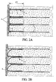
Figure 2A is a schematic view in lateral section of a reinforced soil structure according to a second embodiment of the invention, while it is being built. - ●
Figure 2B is a schematic view in lateral section of a reinforced soil structure as represented infigure 2A , after the main reinforcement members have accidently been disconnected from the facing. - ●
Figure 3 is a schematic perspective view of a facing element usable in an embodiment of the invention. - ●
Figures 4 and 5 are schematic elevation and top views of a facing element usable in another embodiment of the invention. - ●
Figure 6 is a schematic elevation view of another embodiment of a structure according to the invention. - ●
Figures 7 and 8 are schematic elevation and top views of yet another embodiment of a structure according to the invention. - According to an embodiment of the invention the reinforced soil structure may comprise a plurality of main and secondary reinforcement members. In the sense of the invention when the reinforced soil structure comprises a plurality of main and secondary reinforcement members the "stiffness of the main and secondary reinforcement members" is to be understood as the stiffness of the main and secondary reinforcement members per unit area of the facing. Thus according to such embodiment the feature "the stiffness of the secondary reinforcement member is lower than or equal to the stiffness of the main reinforcement member" is to be understood as k2 x n2 is lower than or equal to k1 x n1, with k1 and k2 respectively the individual stiffness of the main and secondary reinforcement members and n1 and n2 respectively the density of the main and secondary reinforcement members per unit area of the facing.
- The figures illustrate the application of the invention to the building of a reinforced soil retaining wall. A compacted fill 1, in which
main reinforcement members 2 are distributed, is delimited on the front side of the structure by a facing 3 formed by juxtaposingprefabricated elements 4, in the form of panels in the embodiment illustrated infigures 1 and2 , and on the rear side by thesoil 5 against which the retaining wall is erected. -
Figure 1 schematically shows the zone Z1 of the fill reinforced with themain reinforcement members 2. - To ensure the cohesion of the retaining wall, the
main reinforcement members 2 are connected to the facingelements 4, and extend over a certain distance within the fill 1. -
Secondary reinforcement members 6 are not positively connected to the facing 3, which dispenses with the need to attach them to specific connectors. Thesesecondary reinforcements 6 extend into the fill 1 from the facing up to a distance substantially shorter than themain reinforcement member 2, with respect to the front face. - According to the invention the stiffness of the
secondary reinforcement members 6 is lower than or equal to the stiffness of themain reinforcement member 2. - Furthermore, these
secondary reinforcements 6 contribute to reinforcing the earth in a zone Z2. - According to an embodiment of the invention the secondary reinforcement members all have substantially the same length and are placed against the facing 3.
- The cohesion of the structure results from the fact that the reinforced zones Z1 and Z2 overlap in a common part Z'. In this common part Z', the material of the fill 1 has good strength because it is reinforced by both the
reinforcement members - It is thus able to withstand the shear stresses exerted as a result of the tensile loads experienced by the reinforcements. This part Z' must naturally be thick enough to hold the facing 3 properly. In practice, a thickness of one to a few meters will generally suffice. By contrast, the
main reinforcement members 2 may extend far more deeply into the fill 1, as shown byfigure 1 . - The simple addition of
secondary reinforcement members 6 into the filling thus allows to reinforce the soil structure in the common part (Z') of the second reinforced zone (Z2) and the first reinforced zone (Z1). - It is preferable to avoid contacts between the
main reinforcement members 2 and thesecondary reinforcement members 6 in the common part Z'. This is because no reliance is placed on the friction forces between reinforcements for reacting the tensile loads given that it is difficult to achieve full control over these friction forces. By contrast, in the reinforced-earth technique, better control is had over the interfaces between reinforcements and fill, which means that the strength properties of the reinforced fill stressed in shear can be relied upon. - In the example depicted, the
main reinforcement members 2 may be synthetic fiber-based strips. They may be connected to the facing 3 in various ways. They may be attached to the facing using conventional connectors, for example of the kind described inEP-A-1 114 896 . - In a preferred embodiment, these
main reinforcement members 2 are incorporated at the time of manufacture of the facingelements 4. In the frequent scenario where theelements 4 are prefabricated in concrete, part of themain reinforcement members 2 may be embedded in the cast concrete of anelement 4. This cast part may in particular form one or more loops around steel bars of the reinforced concrete of theelements 4, thus firmly securing them to the facing. - In the exemplary structure configuration illustrated by
figure 1 , themain reinforcement members 2 and thesecondary reinforcement members 6 are arranged in horizontal planes that are superposed in alternation over the height of the structure. Just two adjacent planes are shown infigure 1 in order to make it easier to read. - The
secondary reinforcement members 6 may be strips of fiber-based synthetic reinforcing material following zigzag paths in horizontal planes behind the facing 3. These may in particular be the reinforcement strips marketed under the trade name "GeoStrap". Such strip advantageously has a width of at most 20 cm. - According to an embodiment illustrated on
figure 2A , the reinforced soil structure may comprise a plurality of main and secondary reinforcement members. - As illustrated on
figure 2A , the main reinforcement members may bemetal bars 2 connected to the facing 4 and the secondary reinforcement members may be selected among the following list consisting of: sheet shaped synthetic grid, ladder shaped synthetic grid, georgrid, geocell, woven or unwoven geotextile layer. - The secondary reinforcement members may be arranged in a U-shape with the base 7 of the U-shape secondary reinforcement extending at least partly along the
facing 4. The two branches 8a and 8b of the u-shape secondary reinforcement extend from the facing in the filling along the main reinforcement member (2, 9, 26) and define the second reinforcement zone (Z2). - According to the embodiment of the invention illustrated on
figure 2A , the two branches 8a and 8b of the u-shape secondary reinforcement member extend into the fill up to substantially the same distance. - According to an embodiment of the invention, the secondary reinforcement members may be arranged such that the two branches 8a and 8b extend into the fill up to different distances.
- As illustrated on
figure 2B , if the main reinforcement members are accidentally disconnected from the facing the reinforced structure is stabilized by the secondary reinforcement members. - In order to build the structure depicted in
figure 1 , the procedure may be as follows: - a) placing some of the facing
elements 4 so as to be able thereafter to introduce fill material over a certain depth. In a known way, the erection and positioning of the facing elements may be made easier by assembly members placed between them; - b) installing, against the facing, a
secondary reinforcement member 6 on the fill already present; - c) introducing fill material over the
secondary reinforcement member 6 which has just been installed, up to the next level of themain reinforcement members 2 on the rear side of the facingelements 4. This fill material is compacted as it is introduced; - d) placing on the fill the
main reinforcement members 2 situated at said level, exerting slight tension thereon; - e) introducing fill material over this level and progressively compacting it until the next specified level for the placement of
secondary reinforcement members 6 is reached; - f) repeating steps a) to e) until the upper level of the fill is reached.
- It should be noted that numerous alternatives may be applied to the structure described hereinabove and to its method of production.
- For example, n order to build the structure depicted in
figure 2A , the procedure may be as follows: - a) placing some of the facing
elements 4 so as to be able thereafter to introduce fill material over a certain depth. In a known way, the erection and positioning of the facing elements may be made easier by assembly members placed between them; - b) laying a first part of the
secondary reinforcement member 6 on the fill already present and the rest of the secondary reinforcement member being temporally laid against the facing; - c) introducing fill material over the first part of the
secondary reinforcement member 6 which has just been installed, up to a level corresponding to the base of the u-shape reinforcement member; - d) laying the free part of the secondary reinforcement member on the fill just added;
- e) introducing fill material over the second part of the
secondary reinforcement member 6 which has just been installed, up to the next level of second branch of the secondary reinforcement member; - f) placing on the fill the
main reinforcement members 2 situated at said level, exerting slight tension thereon; - g) introducing fill material over this level and progressively compacting it until the next specified level for the placement of
secondary reinforcement members 6 is reached; - h) repeating steps a) to g) until the upper level of the fill is reached.
- First, the
main reinforcement members 2 may adopt very diverse forms, as is done in the reinforced soil technique (synthetic strip, metal bar, metal or synthetic grating in the form of a strip, a layer, a ladder, etc), woven or non- woven geotextile layer, etc. with the proviso that the stiffness of the secondary reinforcement member be lower or equal to the stiffness of the main reinforcement member. - Likewise, all kinds of facings may be used: prefabricated elements in the form of panels, blocks, etc, metal gratings, planters, etc. Furthermore, it is perfectly conceivable to build the facing 3 by casting it in situ using concrete or special cements, taking care to connect the
secondary elements 6 therein. - The three-dimensional configurations adopted for the main reinforcement strips 2 and the
secondary elements 6 within the fill 1 may also be very diverse. It is possible to findmain reinforcements 2 andsecondary elements 6 in the same horizontal plane (preferably avoiding contact with one another). It is also possible to have, in the common part Z', a varying ratio between the density of themain reinforcements 2 and that of thesecondary members 6. - In the embodiment illustrated in
figure 3 , the facingelement 14 is equipped with a main reinforcement strip which follows a C-shapedpath 15 when seen in a vertical section. The strip (not shown to display the shape of the path) is embedded in the concrete as it is poured into the manufacturing mould. It preferably passes around one or moremetallic rods 16 used to reinforce the concrete element. The ends of the C-shapedpath 15, at the level at the rear side of the facing element, guide the projecting sections of the strip in horizontal directions. Such strip sections provide a pair of main reinforcement members which emerge from the facingelement 14 into the fill 1 at vertically offset positions. This arrangement takes advantage of the soil/plastic friction on both sides of each strip section, thus optimizing the use of the reinforcement material in zone Z1. - In the alternative embodiment illustrated in
figures 4 and 5 , themain reinforcement member 26 forms a loop around ametallic reinforcement rod 27 of theconcrete facing element 24. Its two projectingsections element 24 in substantially the same horizontal plane. But in that plane (figure 5 ), their angles with respect of the rear surface of the element are different. The twostrip sections - One of the significant advantages of the proposed structure is that it makes it possible to adopt very varied configurations and placement densities for the
main reinforcement members secondary members 6 because the transmission of loads by the fill material situated between them eliminates most of the constructional constraints associated with the method of connection between the main reinforcements and the facing. It will thus be possible to find, within one and the same structure, regions where the relative densities ofmain reinforcement members 26 and/or ofsecondary reinforcement members 6 vary significantly, while they are optimized individually. - An important advantage of the use of geotexiles situatued against the facing but disconnected from the facing as the
secondary reinforcement members 6 is that it provides a very good restraint for the fill in occurrence of an accidental rupture of one or several connections between main reinforcements and facing elements. - In the embodiment shown in
figure 6 , the facing is made ofblocks 44 of relatively small dimensions. These blocks are individually connected to the stabilized soil structure by means ofmain reinforcement members 2. Such arrangement ensures the individual stability of the blocks, and avoids offsets between adjacent blocks without requiring strong positive connections between the blocks. As shown in the figure, the density of thesecondary reinforcement member 6 in zone Z1 may be lower than that of themain reinforcement members 2 in zone Z2. - Since, in this application, the reinforcement density in zone Z2 is set by the dimensions of the
blocks 44, it is seen that the invention enables to optimize the amount of secondary reinforcement members to be used, which is an important economic advantage. - The invention is also interesting in reinforced soil structures whose facing is made of deformable panels, as illustrated in
figures 8 and 9.Such panels 54 may consist of a mesh of welded wires to whichsoil reinforcements 56 are connected, directly or via intermediate devices. Usually, the deformation of such wire mesh facing is limited by increasing the number of connection points and reinforcements. Again, the requirement to consolidate the facing leads to a higher expenditure for the reinforcements to be used. This problem is circumvented by the present invention since it permits to design the reinforcement of zone Z2 by means of thesecondary reinforcement members 6 independently of that of the facing connection zone Z1 by means of thesoil reinforcements 56 used as main reinforcement members. - When a
secondary reinforcement member 6 is being placed on a level of the fill (step b above), it is possible to connect thisreinforcement strip 2 to the facing by means of temporary attachments intended to break as the structure is gradually loaded with the overlying fill levels. Such temporary attachments, which are optional, make correct positioning of the main reinforcements easier, but are not relied upon to transmit load at the facing/fill interface once the structure is completed. - The invention has been described above with the aid of an embodiment without limitation of the general inventive concept.
Claims (14)
- A reinforced soil structure comprising:- a fill (1);- a facing (3) placed along a front face of the structure;- at least one main reinforcement member (2, 9, 26) connected to the facing and extending through a first reinforced zone (Z1) of the fill situated behind said front face; and- at least one secondary reinforcement member (6) disconnected from the facing and extending from the facing (3) in a second reinforced zone (Z2) of the fill which has, with said first reinforced zone (Z1), a common part (Z'),
wherein the secondary reinforcement member (6) extends from the facing into the fill (1) up to a distance substantially shorter than the main reinforcement member (2, 9, 26), with respect to the front face. - The structure according to claim 1 wherein the stiffness of the secondary reinforcement member (6) is lower than or equal to the stiffness of the main reinforcement member (2, 9, 26).
- The structure according to any of claim 1 or 2s, wherein the main reinforcement member is selected among the following list consisting of: metal strip, metal bar, strip shaped metal grid, sheet shaped metal grid, ladder shaped metal grating, synthetic strip, sheet shaped synthetic grid, ladder shaped synthetic grid, geotextile layer, geocell.
- The structure according to any of the preceding claims, wherein the secondary reinforcement member is selected among the following list consisting of:synthetic strip, metal strip, metal bar, sheet shaped metal grid, ladder shaped metal grid, synthetic strip, sheet shaped synthetic grid, ladder shaped synthetic grid, georgrid, geocell, woven or unwoven geotextile layer.
- The structure according to any of the preceding claims, wherein the facing (3) comprises prefabricated elements (4, 14, 24) to which the main reinforcement member (2, 9, 26) is connected.
- The structure according to any of the preceding claims, wherein the secondary reinforcement member (6) is arranged in a U-shape with the base of the U-shape secondary reinforcement extending at least partly along the facing and the two branches of the u-shape secondary reinforcement extending from the facing in the second reinforcement zone (Z2).
- The structure according to claim 6, wherein at least one of the branches of the u-shape secondary reinforcement extends from the facing in the second reinforcement zone (Z2) along the main reinforcement member (2, 9, 26).
- The structure according to claim 6 or 7, wherein the two branches of the u-shape secondary reinforcement member extend into the fill (1) up to substantially the same distance.
- The structure according to any of claims 6 to 8, wherein the main reinforcement member is selected among the following list consisting of: a metal bar, strip shaped metal grid, sheet shaped metal grid, ladder shaped metal grating.
- The structure according to any of the claims 6 to 8, wherein the secondary reinforcement member is selected among the following list consisting of: sheet shaped synthetic grid, ladder shaped synthetic grid, georgrid, geocell, woven or unwoven geotextile layer.
- The structure according to any of the preceding claims, wherein the secondary reinforcement member (6) is not permanently connected to the facing (3).
- A method for building a reinforced soil structure, comprising the steps of:- positioning a facing (3) along a front face of the structure delimiting a volume to be filled;- placing at least one main reinforcement member (2, 9, 26) in a first reinforced zone (Z1) of said volume, wherein the main reinforcement member is connected to the facing and extend through the first reinforced zone (Z1);- placing at least one secondary reinforcement member (6) against the facing not permanently connected to the facing in a second reinforced zone (Z2) of said volume extending from the facing (3), said first and second zones having a part in common (Z'), wherein the secondary reinforcement member (6) is installed from the facing up to a distance substantially shorter than the main reinforcement member (2, 9, 26) with respect to the front face, and wherein the stiffness of the secondary reinforcement member (6) is lower or equal to the stiffness of the main reinforcement member (2, 9, 26);- introducing fill material (1) into said volume and compacting the fill material.
- The method according to claim 12, further comprising the step of determining independently an optimal configuration and density of a plurality of main reinforcement members (2, 9, 26) in said first reinforced zone (Z1) and an optimal configuration and density of a plurality of secondary members (6) in said second reinforced zone (Z2).
- The method according to claim 13, further comprising the step of connecting at least some of the secondary reinforcement strips (6) to the facing (3) by means of temporary attachments designed to break in the step of introducing and compacting the fill material.
Priority Applications (6)
| Application Number | Priority Date | Filing Date | Title |
|---|---|---|---|
| ES10306033.1T ES2564638T3 (en) | 2010-09-24 | 2010-09-24 | A reinforced floor structure |
| DK10306033.1T DK2434059T3 (en) | 2010-09-24 | 2010-09-24 | A reinforced soil structure |
| PL10306033T PL2434059T3 (en) | 2010-09-24 | 2010-09-24 | A reinforced soil structure |
| EP10306033.1A EP2434059B1 (en) | 2010-09-24 | 2010-09-24 | A reinforced soil structure |
| US13/237,715 US8807878B2 (en) | 2010-09-24 | 2011-09-20 | Reinforced soil structure |
| JP2011207428A JP2012072650A (en) | 2010-09-24 | 2011-09-22 | Reinforced soil structure |
Applications Claiming Priority (1)
| Application Number | Priority Date | Filing Date | Title |
|---|---|---|---|
| EP10306033.1A EP2434059B1 (en) | 2010-09-24 | 2010-09-24 | A reinforced soil structure |
Publications (2)
| Publication Number | Publication Date |
|---|---|
| EP2434059A1 true EP2434059A1 (en) | 2012-03-28 |
| EP2434059B1 EP2434059B1 (en) | 2015-12-23 |
Family
ID=43725746
Family Applications (1)
| Application Number | Title | Priority Date | Filing Date |
|---|---|---|---|
| EP10306033.1A Not-in-force EP2434059B1 (en) | 2010-09-24 | 2010-09-24 | A reinforced soil structure |
Country Status (6)
| Country | Link |
|---|---|
| US (1) | US8807878B2 (en) |
| EP (1) | EP2434059B1 (en) |
| JP (1) | JP2012072650A (en) |
| DK (1) | DK2434059T3 (en) |
| ES (1) | ES2564638T3 (en) |
| PL (1) | PL2434059T3 (en) |
Families Citing this family (5)
| Publication number | Priority date | Publication date | Assignee | Title |
|---|---|---|---|---|
| PL2434060T3 (en) * | 2010-09-24 | 2014-09-30 | Terre Armee Int | A reinforced soil structure |
| US20140345220A1 (en) * | 2013-05-24 | 2014-11-27 | Francesco Ferraiolo | Anchoring system for concrete panels in a stabilized earth structure |
| JP6370295B2 (en) * | 2013-05-31 | 2018-08-08 | 国立研究開発法人農業・食品産業技術総合研究機構 | Embankment reinforcement structure and its construction method |
| AU2014326302B2 (en) * | 2013-09-30 | 2018-03-22 | Geotech Technologies Ltd. | Pavement systems with geocell and geogrid |
| MX2020010046A (en) * | 2018-03-28 | 2021-01-15 | Tensar Int Corporation | Geosynthetic reinforced wall panels comprising soil reinforcing hoop members and retaining wall system formed therewith. |
Citations (5)
| Publication number | Priority date | Publication date | Assignee | Title |
|---|---|---|---|---|
| EP0603460A1 (en) * | 1992-12-24 | 1994-06-29 | RDB PLASTOTECNICA S.p.A. | Internally reinforced geotechnical structure and process for manufacturing the same |
| EP1114896A1 (en) | 2000-01-07 | 2001-07-11 | Freyssinet International (STUP) | System for fastening a reinforcement strip to a retaining wall and apparatus for positioning the system |
| DE10311597A1 (en) * | 2003-03-14 | 2004-09-23 | Huesker Synthetic Gmbh | Method for constructing an earth embankment involves introduction of at least a few layers of load distributing elements during or after construction of a consolidated central region |
| FR2922234A1 (en) * | 2008-03-04 | 2009-04-17 | Terre Armee Internationale Soc | FLEXIBLE STABILIZING STRIP INTENDED FOR USE IN REINFORCED STRUCTURED WORKS |
| FR2939157A1 (en) * | 2008-12-02 | 2010-06-04 | Terre Armee Int | REINFORCED GROUND WORK AND FACING ELEMENTS FOR ITS CONSTRUCTION |
Family Cites Families (6)
| Publication number | Priority date | Publication date | Assignee | Title |
|---|---|---|---|---|
| IT1290702B1 (en) * | 1997-02-25 | 1998-12-10 | Maccaferri Spa Off | ELEMENT FOR THE CONSTRUCTION OF STRUCTURES FOR COVERING, CONTAINMENT AND REINFORCEMENT OF LAND, IN PARTICULAR FOR |
| US6238144B1 (en) * | 1997-04-28 | 2001-05-29 | John W. Babcock | Retaining wall and fascia system |
| JP2003003474A (en) * | 2001-06-27 | 2003-01-08 | Kyokado Eng Co Ltd | Reinforcing earth structure and reinforcing earth block |
| JP2004250980A (en) * | 2003-02-20 | 2004-09-09 | Mitsubishi Kagaku Sanshi Corp | Reinforced soil wall structure and construction method |
| FR2860811A1 (en) * | 2003-10-13 | 2005-04-15 | Freyssinet Int Stup | REINFORCED GROUND WORK AND METHOD FOR ITS CONSTRUCTION |
| FR2878268B1 (en) * | 2004-11-25 | 2007-02-09 | Freyssinet Internat Stup Soc P | REINFORCED GROUND WORK AND FACING ELEMENTS FOR ITS CONSTRUCTION |
-
2010
- 2010-09-24 EP EP10306033.1A patent/EP2434059B1/en not_active Not-in-force
- 2010-09-24 PL PL10306033T patent/PL2434059T3/en unknown
- 2010-09-24 DK DK10306033.1T patent/DK2434059T3/en active
- 2010-09-24 ES ES10306033.1T patent/ES2564638T3/en active Active
-
2011
- 2011-09-20 US US13/237,715 patent/US8807878B2/en not_active Expired - Fee Related
- 2011-09-22 JP JP2011207428A patent/JP2012072650A/en active Pending
Patent Citations (5)
| Publication number | Priority date | Publication date | Assignee | Title |
|---|---|---|---|---|
| EP0603460A1 (en) * | 1992-12-24 | 1994-06-29 | RDB PLASTOTECNICA S.p.A. | Internally reinforced geotechnical structure and process for manufacturing the same |
| EP1114896A1 (en) | 2000-01-07 | 2001-07-11 | Freyssinet International (STUP) | System for fastening a reinforcement strip to a retaining wall and apparatus for positioning the system |
| DE10311597A1 (en) * | 2003-03-14 | 2004-09-23 | Huesker Synthetic Gmbh | Method for constructing an earth embankment involves introduction of at least a few layers of load distributing elements during or after construction of a consolidated central region |
| FR2922234A1 (en) * | 2008-03-04 | 2009-04-17 | Terre Armee Internationale Soc | FLEXIBLE STABILIZING STRIP INTENDED FOR USE IN REINFORCED STRUCTURED WORKS |
| FR2939157A1 (en) * | 2008-12-02 | 2010-06-04 | Terre Armee Int | REINFORCED GROUND WORK AND FACING ELEMENTS FOR ITS CONSTRUCTION |
Also Published As
| Publication number | Publication date |
|---|---|
| ES2564638T3 (en) | 2016-03-28 |
| DK2434059T3 (en) | 2016-03-21 |
| US20120076592A1 (en) | 2012-03-29 |
| US8807878B2 (en) | 2014-08-19 |
| JP2012072650A (en) | 2012-04-12 |
| PL2434059T3 (en) | 2016-06-30 |
| EP2434059B1 (en) | 2015-12-23 |
Similar Documents
| Publication | Publication Date | Title |
|---|---|---|
| US9080303B2 (en) | Reinforced soil structure | |
| CA2518184C (en) | Reinforced soil structure and method for constructing it | |
| EP2729627B1 (en) | Foundation system for bridges and other structures | |
| US7491018B2 (en) | Stabilized soil structure and facing elements for its construction | |
| US8807878B2 (en) | Reinforced soil structure | |
| US8568057B2 (en) | Full precast traffic barrier and installation method for mechanically stabilized earth wall structures | |
| KR101136240B1 (en) | made of iron soil retaining plate and its support structure for form and retaining-wall vertical reinforcement | |
| US20120114431A1 (en) | Connection Device For A Reinforced Earth Structure And Related Structure And Method | |
| KR101287739B1 (en) | Sheet pile combined modular bridge abutment and construction method of the same | |
| KR100403835B1 (en) | Reinforcements for bending-moment and shear in the part of reinforced concrete footings and construction method of its using | |
| EP2931976B1 (en) | Foundation system for bridges and other structures | |
| KR100919921B1 (en) | Retaining Wall using Panel and Constructing Method thereof | |
| JP5184393B2 (en) | Protective wall and protective wall forming method | |
| CN108252325B (en) | Buttress rib stake formula stake board retaining wall | |
| KR101275000B1 (en) | Steel composite girder structure and construction method thereof | |
| KR20130041553A (en) | Precast block wall, cantilevered slab bridge using precast block wall and construction method thereof |
Legal Events
| Date | Code | Title | Description |
|---|---|---|---|
| PUAI | Public reference made under article 153(3) epc to a published international application that has entered the european phase |
Free format text: ORIGINAL CODE: 0009012 |
|
| AK | Designated contracting states |
Kind code of ref document: A1 Designated state(s): AL AT BE BG CH CY CZ DE DK EE ES FI FR GB GR HR HU IE IS IT LI LT LU LV MC MK MT NL NO PL PT RO SE SI SK SM TR |
|
| AX | Request for extension of the european patent |
Extension state: BA ME RS |
|
| 17P | Request for examination filed |
Effective date: 20120319 |
|
| RIC1 | Information provided on ipc code assigned before grant |
Ipc: E02D 29/02 20060101AFI20140821BHEP |
|
| GRAP | Despatch of communication of intention to grant a patent |
Free format text: ORIGINAL CODE: EPIDOSNIGR1 |
|
| INTG | Intention to grant announced |
Effective date: 20141002 |
|
| RIN1 | Information on inventor provided before grant (corrected) |
Inventor name: LUCAS, ERIC Inventor name: FREITAG, NICOLAS |
|
| RAP1 | Party data changed (applicant data changed or rights of an application transferred) |
Owner name: TERRE ARMEE INTERNATIONALE |
|
| GRAS | Grant fee paid |
Free format text: ORIGINAL CODE: EPIDOSNIGR3 |
|
| GRAP | Despatch of communication of intention to grant a patent |
Free format text: ORIGINAL CODE: EPIDOSNIGR1 |
|
| INTG | Intention to grant announced |
Effective date: 20150708 |
|
| GRAA | (expected) grant |
Free format text: ORIGINAL CODE: 0009210 |
|
| AK | Designated contracting states |
Kind code of ref document: B1 Designated state(s): AL AT BE BG CH CY CZ DE DK EE ES FI FR GB GR HR HU IE IS IT LI LT LU LV MC MK MT NL NO PL PT RO SE SI SK SM TR |
|
| REG | Reference to a national code |
Ref country code: GB Ref legal event code: FG4D |
|
| REG | Reference to a national code |
Ref country code: CH Ref legal event code: EP |
|
| REG | Reference to a national code |
Ref country code: IE Ref legal event code: FG4D |
|
| REG | Reference to a national code |
Ref country code: AT Ref legal event code: REF Ref document number: 766627 Country of ref document: AT Kind code of ref document: T Effective date: 20160115 |
|
| REG | Reference to a national code |
Ref country code: DE Ref legal event code: R096 Ref document number: 602010029679 Country of ref document: DE |
|
| REG | Reference to a national code |
Ref country code: DK Ref legal event code: T3 Effective date: 20160315 |
|
| REG | Reference to a national code |
Ref country code: ES Ref legal event code: FG2A Ref document number: 2564638 Country of ref document: ES Kind code of ref document: T3 Effective date: 20160328 |
|
| REG | Reference to a national code |
Ref country code: SE Ref legal event code: TRGR |
|
| REG | Reference to a national code |
Ref country code: NL Ref legal event code: FP |
|
| REG | Reference to a national code |
Ref country code: LT Ref legal event code: MG4D |
|
| PG25 | Lapsed in a contracting state [announced via postgrant information from national office to epo] |
Ref country code: NO Free format text: LAPSE BECAUSE OF FAILURE TO SUBMIT A TRANSLATION OF THE DESCRIPTION OR TO PAY THE FEE WITHIN THE PRESCRIBED TIME-LIMIT Effective date: 20160323 Ref country code: LT Free format text: LAPSE BECAUSE OF FAILURE TO SUBMIT A TRANSLATION OF THE DESCRIPTION OR TO PAY THE FEE WITHIN THE PRESCRIBED TIME-LIMIT Effective date: 20151223 Ref country code: HR Free format text: LAPSE BECAUSE OF FAILURE TO SUBMIT A TRANSLATION OF THE DESCRIPTION OR TO PAY THE FEE WITHIN THE PRESCRIBED TIME-LIMIT Effective date: 20151223 |
|
| REG | Reference to a national code |
Ref country code: AT Ref legal event code: MK05 Ref document number: 766627 Country of ref document: AT Kind code of ref document: T Effective date: 20151223 |
|
| PG25 | Lapsed in a contracting state [announced via postgrant information from national office to epo] |
Ref country code: GR Free format text: LAPSE BECAUSE OF FAILURE TO SUBMIT A TRANSLATION OF THE DESCRIPTION OR TO PAY THE FEE WITHIN THE PRESCRIBED TIME-LIMIT Effective date: 20160324 Ref country code: LV Free format text: LAPSE BECAUSE OF FAILURE TO SUBMIT A TRANSLATION OF THE DESCRIPTION OR TO PAY THE FEE WITHIN THE PRESCRIBED TIME-LIMIT Effective date: 20151223 Ref country code: FI Free format text: LAPSE BECAUSE OF FAILURE TO SUBMIT A TRANSLATION OF THE DESCRIPTION OR TO PAY THE FEE WITHIN THE PRESCRIBED TIME-LIMIT Effective date: 20151223 |
|
| PG25 | Lapsed in a contracting state [announced via postgrant information from national office to epo] |
Ref country code: CZ Free format text: LAPSE BECAUSE OF FAILURE TO SUBMIT A TRANSLATION OF THE DESCRIPTION OR TO PAY THE FEE WITHIN THE PRESCRIBED TIME-LIMIT Effective date: 20151223 |
|
| REG | Reference to a national code |
Ref country code: FR Ref legal event code: PLFP Year of fee payment: 7 |
|
| PG25 | Lapsed in a contracting state [announced via postgrant information from national office to epo] |
Ref country code: RO Free format text: LAPSE BECAUSE OF FAILURE TO SUBMIT A TRANSLATION OF THE DESCRIPTION OR TO PAY THE FEE WITHIN THE PRESCRIBED TIME-LIMIT Effective date: 20151223 Ref country code: IS Free format text: LAPSE BECAUSE OF FAILURE TO SUBMIT A TRANSLATION OF THE DESCRIPTION OR TO PAY THE FEE WITHIN THE PRESCRIBED TIME-LIMIT Effective date: 20160423 Ref country code: AT Free format text: LAPSE BECAUSE OF FAILURE TO SUBMIT A TRANSLATION OF THE DESCRIPTION OR TO PAY THE FEE WITHIN THE PRESCRIBED TIME-LIMIT Effective date: 20151223 Ref country code: SM Free format text: LAPSE BECAUSE OF FAILURE TO SUBMIT A TRANSLATION OF THE DESCRIPTION OR TO PAY THE FEE WITHIN THE PRESCRIBED TIME-LIMIT Effective date: 20151223 Ref country code: EE Free format text: LAPSE BECAUSE OF FAILURE TO SUBMIT A TRANSLATION OF THE DESCRIPTION OR TO PAY THE FEE WITHIN THE PRESCRIBED TIME-LIMIT Effective date: 20151223 Ref country code: SK Free format text: LAPSE BECAUSE OF FAILURE TO SUBMIT A TRANSLATION OF THE DESCRIPTION OR TO PAY THE FEE WITHIN THE PRESCRIBED TIME-LIMIT Effective date: 20151223 Ref country code: PT Free format text: LAPSE BECAUSE OF FAILURE TO SUBMIT A TRANSLATION OF THE DESCRIPTION OR TO PAY THE FEE WITHIN THE PRESCRIBED TIME-LIMIT Effective date: 20160426 |
|
| REG | Reference to a national code |
Ref country code: DE Ref legal event code: R097 Ref document number: 602010029679 Country of ref document: DE |
|
| PLBE | No opposition filed within time limit |
Free format text: ORIGINAL CODE: 0009261 |
|
| STAA | Information on the status of an ep patent application or granted ep patent |
Free format text: STATUS: NO OPPOSITION FILED WITHIN TIME LIMIT |
|
| 26N | No opposition filed |
Effective date: 20160926 |
|
| PG25 | Lapsed in a contracting state [announced via postgrant information from national office to epo] |
Ref country code: BE Free format text: LAPSE BECAUSE OF FAILURE TO SUBMIT A TRANSLATION OF THE DESCRIPTION OR TO PAY THE FEE WITHIN THE PRESCRIBED TIME-LIMIT Effective date: 20151223 |
|
| PG25 | Lapsed in a contracting state [announced via postgrant information from national office to epo] |
Ref country code: SI Free format text: LAPSE BECAUSE OF FAILURE TO SUBMIT A TRANSLATION OF THE DESCRIPTION OR TO PAY THE FEE WITHIN THE PRESCRIBED TIME-LIMIT Effective date: 20151223 |
|
| PG25 | Lapsed in a contracting state [announced via postgrant information from national office to epo] |
Ref country code: MC Free format text: LAPSE BECAUSE OF FAILURE TO SUBMIT A TRANSLATION OF THE DESCRIPTION OR TO PAY THE FEE WITHIN THE PRESCRIBED TIME-LIMIT Effective date: 20151223 |
|
| REG | Reference to a national code |
Ref country code: CH Ref legal event code: PL |
|
| REG | Reference to a national code |
Ref country code: IE Ref legal event code: MM4A |
|
| PG25 | Lapsed in a contracting state [announced via postgrant information from national office to epo] |
Ref country code: IE Free format text: LAPSE BECAUSE OF NON-PAYMENT OF DUE FEES Effective date: 20160924 Ref country code: CH Free format text: LAPSE BECAUSE OF NON-PAYMENT OF DUE FEES Effective date: 20160930 Ref country code: LI Free format text: LAPSE BECAUSE OF NON-PAYMENT OF DUE FEES Effective date: 20160930 |
|
| REG | Reference to a national code |
Ref country code: FR Ref legal event code: PLFP Year of fee payment: 8 |
|
| PG25 | Lapsed in a contracting state [announced via postgrant information from national office to epo] |
Ref country code: LU Free format text: LAPSE BECAUSE OF NON-PAYMENT OF DUE FEES Effective date: 20160924 |
|
| PG25 | Lapsed in a contracting state [announced via postgrant information from national office to epo] |
Ref country code: CY Free format text: LAPSE BECAUSE OF FAILURE TO SUBMIT A TRANSLATION OF THE DESCRIPTION OR TO PAY THE FEE WITHIN THE PRESCRIBED TIME-LIMIT Effective date: 20151223 Ref country code: HU Free format text: LAPSE BECAUSE OF FAILURE TO SUBMIT A TRANSLATION OF THE DESCRIPTION OR TO PAY THE FEE WITHIN THE PRESCRIBED TIME-LIMIT; INVALID AB INITIO Effective date: 20100924 |
|
| PG25 | Lapsed in a contracting state [announced via postgrant information from national office to epo] |
Ref country code: TR Free format text: LAPSE BECAUSE OF FAILURE TO SUBMIT A TRANSLATION OF THE DESCRIPTION OR TO PAY THE FEE WITHIN THE PRESCRIBED TIME-LIMIT Effective date: 20151223 Ref country code: MT Free format text: LAPSE BECAUSE OF NON-PAYMENT OF DUE FEES Effective date: 20160930 Ref country code: MK Free format text: LAPSE BECAUSE OF FAILURE TO SUBMIT A TRANSLATION OF THE DESCRIPTION OR TO PAY THE FEE WITHIN THE PRESCRIBED TIME-LIMIT Effective date: 20151223 |
|
| PG25 | Lapsed in a contracting state [announced via postgrant information from national office to epo] |
Ref country code: BG Free format text: LAPSE BECAUSE OF FAILURE TO SUBMIT A TRANSLATION OF THE DESCRIPTION OR TO PAY THE FEE WITHIN THE PRESCRIBED TIME-LIMIT Effective date: 20151223 |
|
| REG | Reference to a national code |
Ref country code: FR Ref legal event code: PLFP Year of fee payment: 9 |
|
| PG25 | Lapsed in a contracting state [announced via postgrant information from national office to epo] |
Ref country code: AL Free format text: LAPSE BECAUSE OF FAILURE TO SUBMIT A TRANSLATION OF THE DESCRIPTION OR TO PAY THE FEE WITHIN THE PRESCRIBED TIME-LIMIT Effective date: 20151223 |
|
| PGFP | Annual fee paid to national office [announced via postgrant information from national office to epo] |
Ref country code: SE Payment date: 20180824 Year of fee payment: 9 |
|
| PGFP | Annual fee paid to national office [announced via postgrant information from national office to epo] |
Ref country code: NL Payment date: 20190826 Year of fee payment: 10 |
|
| PGFP | Annual fee paid to national office [announced via postgrant information from national office to epo] |
Ref country code: PL Payment date: 20190822 Year of fee payment: 10 |
|
| PGFP | Annual fee paid to national office [announced via postgrant information from national office to epo] |
Ref country code: GB Payment date: 20190820 Year of fee payment: 10 |
|
| REG | Reference to a national code |
Ref country code: DK Ref legal event code: EBP Effective date: 20190930 |
|
| PG25 | Lapsed in a contracting state [announced via postgrant information from national office to epo] |
Ref country code: SE Free format text: LAPSE BECAUSE OF NON-PAYMENT OF DUE FEES Effective date: 20190925 |
|
| REG | Reference to a national code |
Ref country code: SE Ref legal event code: EUG |
|
| PG25 | Lapsed in a contracting state [announced via postgrant information from national office to epo] |
Ref country code: IT Free format text: LAPSE BECAUSE OF NON-PAYMENT OF DUE FEES Effective date: 20190924 |
|
| PG25 | Lapsed in a contracting state [announced via postgrant information from national office to epo] |
Ref country code: DK Free format text: LAPSE BECAUSE OF NON-PAYMENT OF DUE FEES Effective date: 20190930 |
|
| PGFP | Annual fee paid to national office [announced via postgrant information from national office to epo] |
Ref country code: DE Payment date: 20200819 Year of fee payment: 11 Ref country code: FR Payment date: 20200819 Year of fee payment: 11 |
|
| PGFP | Annual fee paid to national office [announced via postgrant information from national office to epo] |
Ref country code: ES Payment date: 20201001 Year of fee payment: 11 |
|
| REG | Reference to a national code |
Ref country code: NL Ref legal event code: MM Effective date: 20201001 |
|
| GBPC | Gb: european patent ceased through non-payment of renewal fee |
Effective date: 20200924 |
|
| PG25 | Lapsed in a contracting state [announced via postgrant information from national office to epo] |
Ref country code: NL Free format text: LAPSE BECAUSE OF NON-PAYMENT OF DUE FEES Effective date: 20201001 |
|
| PG25 | Lapsed in a contracting state [announced via postgrant information from national office to epo] |
Ref country code: GB Free format text: LAPSE BECAUSE OF NON-PAYMENT OF DUE FEES Effective date: 20200924 |
|
| REG | Reference to a national code |
Ref country code: DE Ref legal event code: R119 Ref document number: 602010029679 Country of ref document: DE |
|
| PG25 | Lapsed in a contracting state [announced via postgrant information from national office to epo] |
Ref country code: FR Free format text: LAPSE BECAUSE OF NON-PAYMENT OF DUE FEES Effective date: 20210930 Ref country code: DE Free format text: LAPSE BECAUSE OF NON-PAYMENT OF DUE FEES Effective date: 20220401 |
|
| REG | Reference to a national code |
Ref country code: ES Ref legal event code: FD2A Effective date: 20221107 |
|
| PG25 | Lapsed in a contracting state [announced via postgrant information from national office to epo] |
Ref country code: PL Free format text: LAPSE BECAUSE OF NON-PAYMENT OF DUE FEES Effective date: 20200924 |
|
| PG25 | Lapsed in a contracting state [announced via postgrant information from national office to epo] |
Ref country code: ES Free format text: LAPSE BECAUSE OF NON-PAYMENT OF DUE FEES Effective date: 20210925 |