EP2433850A1 - Torque rod mounting structure for motor vehicle - Google Patents
Torque rod mounting structure for motor vehicle Download PDFInfo
- Publication number
- EP2433850A1 EP2433850A1 EP11183122A EP11183122A EP2433850A1 EP 2433850 A1 EP2433850 A1 EP 2433850A1 EP 11183122 A EP11183122 A EP 11183122A EP 11183122 A EP11183122 A EP 11183122A EP 2433850 A1 EP2433850 A1 EP 2433850A1
- Authority
- EP
- European Patent Office
- Prior art keywords
- bracket
- torque rod
- damper housing
- side flange
- vehicle body
- Prior art date
- Legal status (The legal status is an assumption and is not a legal conclusion. Google has not performed a legal analysis and makes no representation as to the accuracy of the status listed.)
- Granted
Links
Images


Classifications
-
- B—PERFORMING OPERATIONS; TRANSPORTING
- B62—LAND VEHICLES FOR TRAVELLING OTHERWISE THAN ON RAILS
- B62D—MOTOR VEHICLES; TRAILERS
- B62D25/00—Superstructure or monocoque structure sub-units; Parts or details thereof not otherwise provided for
- B62D25/08—Front or rear portions
- B62D25/088—Details of structures as upper supports for springs or dampers
Landscapes
- Engineering & Computer Science (AREA)
- Chemical & Material Sciences (AREA)
- Combustion & Propulsion (AREA)
- Transportation (AREA)
- Mechanical Engineering (AREA)
- Body Structure For Vehicles (AREA)
- Arrangement Or Mounting Of Propulsion Units For Vehicles (AREA)
Abstract
Description
- The present invention relates to a torque rod mounting structure for mounting one end of a torque rod to a vehicle body with an opposite end of the torque rod being connected to an engine.
- Torque rod mounting structures of the type concerned are known as disclosed in, for example, Japanese Patent Application Laid-open Publication (JP-A) No.
2009-248616 - The foregoing torque rod mounting structure is, however, not fully satisfactory in that in order to deal with a large engine torque with increased vibration suppressing efficiency, the mounting bracket needs to be thickened, and the thickened mounting bracket is heavy itself and increases the size and weight of the entire torque rod mounting structure.
- It is therefore an object of the present invention to provide a torque rod mounting structure which is capable of suppressing vibration of an engine with increased efficiency, can lower the weight of a mounting bracket while keeping a desired level of strength of the bracket, and is able to prevent generation of unpleasant vibration noise.
- According to the present invention, there is provided a torque rod mounting structure for mounting one end of a torque rod to a vehicle body with an opposite end of the torque rod being connected to an engine installed in an engine room of the vehicle body, the torque rod mounting structure comprising: a damper housing forming a part of the vehicle body and facing the engine room; and a bracket assembly including: an upper bracket attached to the damper housing and projecting from the damper housing into the engine room, the upper bracket having a front end portion disposed above and connected to the one end of the torque rod; a lower bracket attached to the damper housing and projecting from the damper housing into the engine room, the lower bracket having a front end portion disposed beneath and connected to the one end of the torque rod; and a stay bracket having a first end attached to the damper housing below the lower bracket and a second end opposite to the first end and connected to the front end portion of the lower bracket, wherein the stay bracket is configured to form, together with the damper housing, a hollow portion having a closed cross section.
- With this arrangement, by virtue of the stay bracket so configured as to form together with the damper housing a hollow portion having a closed cross section, a load applied from the torque rod to the bracket assembly is distributed in a branched fashion to the damper housing. By thus distributing the applied load, it is possible to increase the load-bearing strength of the bracket assembly and also to suppress vibration of the engine with increased efficiency while allowing use of a relatively thin sheet metal for the bracket assembly, which will achieve a certain weight reduction of the bracket assembly.
- Preferably, the damper housing has a vertical bead of convex cross section projecting in a width direction of the vehicle body into the engine room and extending in a vertical direction of the vehicle body, the upper bracket has a rear end connected to the vertical bead, and the lower bracket has a rear end connected to the vertical bead. The load applied from the torque rod to the bracket assembly is distributed in a branched fashion to the damper assembly as it is transmitted from the rear ends of the upper and lower brackets to the vertical bead of the damper bracket. By thus distributing the applied load, it is possible to increase the load-bearing capacity of the torque rod mounting structure.
- Preferably, the upper bracket has a side flange facing toward a lateral inward direction of the vehicle body and forming a part of the rear end of the upper bracket, the lower bracket has a side flange facing toward the lateral inward direction of the vehicle body and forming a part of the rear end of the lower bracket, and the side flange of the upper bracket has a stepped lower end portion rising toward the lateral inward direction of the vehicle body at a height greater than a thickness of the side flange of the lower bracket, the stepped lower end portion being joined with the side flange of the lower bracket. By thus providing the stepped lower end portion, the side flange of the upper bracket can be placed on the side flange of the lower bracket from the engine room side in such a manner that respective surfaces of the side flanges which face the damper housing lie substantially flush with each other. This arrangement can eliminate the need for a recessed portion formed in the vertical bead for accommodating the thickness of the side flange of the lower bracket, which may lead to reduction of the load-bearing capacity of the torque rod mounting structure.
- Preferably, the vertical bead of the damper housing has a protrusion disposed in a longitudinal intermediate portion of the vertical bead, the side flange of the lower bracket has a stepped lower end portion rising toward the lateral inward direction of the vehicle body at a height smaller than a height of the protrusion and joined with the protrusion of the vertical bead. With this arrangement, a joint portion between the upper bracket and the lower bracket forms a non-contact portion relative to the damper housing. In order to prevent generation of unpleasant vibration noise, it is desired that a space be provided between the joint portion and the damper housing. In this instance, if the space is excessively small, it will lead to generation of unpleasant vibration noise. Alternatively, if the space is excessively large, it will lead to reduction in bonding strength of the joint portion. However, according to the present invention, the stepped lower end portion of the side flange of the lower bracket serves to effectively block or prevent vibration from transmitting from a joint portion between the lower bracket and the damper housing to the joint portion between the side flanges of the upper and lower brackets, and also to keep the space between the joint portion between the upper and lower bracket and the damper housing within a desired range, thereby securing a desired bonding strength of the joint portion.
- Preferably, the stepped lower end portion of the side flange of the upper bracket and the stepped lower end portion of the side flange of the lower bracket extend in a front-rear direction of the vehicle body. The thus arranged stepped lower end portions of the upper and lower brackets increase the strength of the upper and lower brackets, which will lead to an increase in the load-bearing strength of the bracket assembly.
- Preferably, the side flange of the lower bracket has a varying height increasing gradually in a direction from a front end toward a rear end of the side flange. With this arrangement, a component of the applied load acting in the front-rear direction of the vehicle body is distributed through the side flange of the lower bracket to a wider area of the damper housing.
-
Fig. 1 is a perspective view of a vehicle front body in which a torque rod mounting structure according to an embodiment of the present invention is incorporated; -
Fig. 2 is a perspective view of the torque rod mounting structure shown with a torque rod removed for clarity; -
Fig. 3 is a view similar toFig. 2 , but showing the torque rod mounting structure with a torque rod being about to be mounted to the vehicle front body via a bracket assembly; -
Fig. 4 is a perspective view as seen from the direction of arrow 4 shown inFig. 3 ; -
Fig. 5 is a cross-sectional view taken along line 5-5 ofFig. 1 ; -
Fig. 6 is an enlarged view of a part indicated by acircle 6 shown inFig. 5 ; -
Fig. 7 is a cross-sectional view taken along line 7-7 ofFig. 2 ; -
Fig. 8 is a cross-sectional view taken along line 8-8 ofFig. 2 ; -
Fig. 9 is a cross-sectional view taken along line 9-9 ofFig. 2 ; -
Fig. 10 is a side view showing a stay bracket of the torque rod mounting structure as it is attached to a damper housing of the vehicle front body; -
Fig. 11 is a cross-sectional view taken along line 11-11 ofFig. 10 ; -
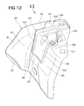
Fig. 12 is a perspective view of the stay bracket and a stiffener as seen from below; and -
Fig. 13 is a cross-sectional view taken along line 13-13 ofFig. 12 . - A preferred structural embodiment of the present invention will be described below in detail with reference to the accompanying sheets of drawings.
- Referring now to
Fig. 1 , there is shown a torquerod mounting structure 10 incorporated in afront body 12 of avehicle 11 for mounting one end of a torque rod 13 (Fig. 3 ) to the vehiclefront body 11 via abracket assembly 15. Thefront body 12 has anengine room 26 in which anengine 17 is installed in such a manner that theengine 17 is supported by the torque rod 13 (Fig. 3 ) and other mounting devices. Theengine 17 has cylinders disposed on a right side thereof and a transmission on a left side thereof that are as viewed from a forward travel direction of the vehicle. The torque rod 13 (Fig. 3 ) is connected to the right side of theengine 17. - The
front body 12 includes left and rightfront side frames right damper housings inner members upper members dashboard 34 isolating apassenger compartment 33 from theengine room 26. - The torque rod 13 (
Fig. 3 ) is used to support theengine 17 onto avehicle body 18 including thefront body 12. Thetorque rod 13 has anend 21 connected via thebracket assembly 15 to thefront body 12. Theend 21 of thetorque rod 13 has a tubular shape and is provided with a vibration isolating member (made of rubber, for example) having asteel bush 22 embedded therein in concentric relation with thetubular end 21. Thesteel bush 22 has a length Hs (Fig. 3 ) and is connected to thebracket assembly 15 by means of abolt 23. Thetorque rod 13 is thus mounted to thefront body 12. - The torque
rod mounting structure 10 of the present invention will be described in greater detail with reference toFigs. 2 to 13 , wherein in several views, a double-headed arrow X denotes a longitudinal or front-rear direction of thevehicle 11, a double-headed arrow Y denotes a transverse or width direction of thevehicle 11, and a double-headed arrow Z denotes a vertical or height direction of thevehicle 11. - The torque
rod mounting structure 10 is generally comprised of thedamper housing 28 and thebracket assembly 15. Thedamper housing 28 forms a part of a wall defining theengine room 26 and, hence, it is disposed to face theengine room 26. Thebracket assembly 15 is attached to and projects from thedamper housing 28 in a cantilevered fashion, so as to support theend 21 of thetorque rod 13 on a front end portion thereof. - More specifically, as shown in
Figs. 2 to 4 , thebracket assembly 15 includes a pair of vertically spaced upper andlower brackets damper housing 28 and projecting from thedamper housing 28 into theengine room 26, and astay bracket 42 having one end (rear end) attached to thedamper housing 28 below thelower bracket 38 and an opposite end (front end) attached to afront end portion 41 of thelower bracket 38. Each of theupper bracket 37,lower bracket 38 and staybracket 42 is formed by press-forming from a sheet metal into a desired shape and configuration. - The
upper bracket 37 has afront end portion 68 disposed above thetubular end 21 of thetorque rod 13 and connected to thetubular end 21. Thefront end portion 41 of thelower bracket 38 is disposed beneath thetubular end 21 of thetorque rod 13 and connected to thetubular end 21. As shown inFigs. 10 and11 , thestay bracket 42 is configured to form, together with thedamper housing 28, ahollow portion 44 having a closed cross section (Fig. 11 ). - The
damper housing 28 has avertical bead 45 protruding convexly into the engine room 26 (in a lateral inward direction of the vehicle body 18) and extending in a vertical direction of thevehicle body 18. Therear end 47 of theupper bracket 37 is connected by spot-welding to thevertical bead 45 of thedamper housing 28. Similarly, therear end 48 of thelower bracket 38 is connected by spot-welding to thevertical bead 45 of thedamper housing 28. - The
upper bracket 37 has alateral side flange 51 extending downwardly from one side edge thereof and facing toward a lateral inward direction of thefront body 12. Theside flange 51 has a rear end portion forming a part of therear end 47 of theupper bracket 37 at which theupper bracket 37 is connected to thevertical bead 45. Similarly, thelower bracket 38 has alateral side flange 52 extending downwardly from one side edge thereof and facing toward a lateral inward direction of thefront body 12. Theside flange 52 has a rear end portion forming a part of therear end 48 of thelower bracket 38. - As shown in
Figs. 2 and6 , theside flange 51 of theupper bracket 37 is stepped as at 54 so as to form a steppedlower end portion 55 of theside flange 51. Thestep 54 has a height S1 (Fig. 6 ) greater than a thickness Tw (Fig. 6 ) of theside flange 52 of thelower bracket 38, and the steppedlower end portion 55 is connected by spot-welding to theside flange 52 of thelower bracket 38. It will be appreciated that the steppedlower end portion 55 of theside flange 51 rises toward a lateral inward direction of thevehicle body 18 at the height S1 of thestep 54. - As shown in
Figs. 2 ,5 ,6 and10 , thevertical bead 45 has acircular protrusion 56 disposed in a longitudinally intermediate potion thereof and projecting into theengine room 26. Theprotrusion 56 has a height Hb (Fig. 6 ). Theside flange 52 of thelower bracket 38 is stepped as at 57 so as to form a steppedlower end portion 58 of theslide flange 52. Thestep 57 has a height S2 (Fig. 6 ) smaller than the height Hb of theprotrusion 56, and the steppedlower end portion 58 is connected by spot-welding to theprotrusion 56. It will be appreciated that the steppedlower end portion 58 of theside flange 52 rises toward the lateral inward direction of thevehicle body 18 at the height S2 of thestep 57. - The stepped
lower end portion 55 of theside flange 51 and the steppedlower end portion 58 of theside flange 52 are parallel to each other and extend in a longitudinal or front-rear direction of thevehicle 11. Theside flange 52 of thelower bracket 38 has a varying height, which increases gradually in a direction from a front end toward a rear end of theside flange 52. - As discussed above, the
damper assembly 15 is composed of theupper bracket 37, thelower bracket 38 and thestay bracket 42 and projects from thedamper housing 28 of thevehicle body 18 into theengine room 26. Thebracket assembly 15 further includes astiffener 64 and is reinforced by thestiffener 64. - As shown in
Figs. 2 ,10 and11 , thedamper housing 28 has aside wall 65 facing toward a lateral inward direction of thevehicle body 18, and afront wall 66 contiguous with theside wall 65 and facing toward a forward direction of thevehicle body 18 as indicated by arrow a1 (Figs. 10 and11 ). Theupper bracket 37 projects from respective upper portions of the side andfront walls damper housing 28. - As shown in
Figs. 2 and3 , theupper bracket 37 has abracket body 71 formed to lie in a substantially horizontal plane and including the front end portion 81 to which thetubular end 21 of thetorque rod 13 is to be connected. Thebracket body 71 has one side edge from which theside flange 51 extends downwards. Theupper bracket 37 also includes arear end flange 72 extending upwardly from a rear end edge of thebracket body 71 and connected by spot-welding to thedamper housing 28, and anotherside flange 73 extending downwardly from an opposite side edge of thebracket body 71 and connected by spot-welding to the wheelhouseinner member 31. - As discussed above, the rear end portion of the
side flange 51 forms a part of therear end 47 of theupper bracket 37 at which theupper bracket 37 is connected to thevertical bead 45 of thedamper housing 28. By virtue of thestep 54 formed on theside flange 51 of theupper bracket 37, a joint portion 128 (Fig. 6 ) between the steppedlower end portion 55 of theside flange 51 of theupper bracket 37 and theside flange 52 of thelower bracket 38 is not connected to thedamper housing 28 but separated from thedamper housing 28 by at least a distance E (Fig. 6 ). More specifically, that part of the rear end portion of theside flange 51, which excludes the steppedlower end portion 55, is directly connected to thedamper housing 28. The steppedlower end portion 55 of theside flange 51 is connected to theside flange 52 of thelower bracket 38. - As shown in
Figs. 2 to 4 , thelower bracket 38 has abracket body 76 formed to lie in a substantially horizontal plane and including thefront end portion 41 to which thetubular end 21 of thetorque rod 13 is to be connected. Thefront end portion 41 of thelower bracket 38 is in contact with a lower end face of thesteel bush 22 provided at theend 21 of the of thetorque rod 13. Thebracket body 76 has one side edge from which theside flange 52 extends downwards. Theside flange 52 has a substantially triangular shape as viewed from a lateral side of thevehicle 11. Thelower bracket 38 also includes a rear end flange 77 (Fig. 2 ) extending upwardly from a rear end edge of thebracket body 76 and connected by spot-welding to thedamper housing 28, and anotherside flange 38a extending downwardly from an opposite side edge of thebracket body 76. - As discussed above, the stepped
lower end portion 58 of theside flange 52 is connected to the protrusion 56 (Fig. 6 ) of thevertical bead 45 of thedamper housing 28. That part of theside flange 52, which excludes the steppedlower end portion 58, and which includes the joint portion 128 (Fig. 6 ) between theside flange 52 of thelower bracket 38 and theside flange 51 of theupper bracket 37, is separated from thedamper housing 28. Thestay bracket 42 is joined to the underside of thelower bracket 38. - As shown in
Figs. 1 and10 to 13 , thestay bracket 42 has a generally inverted L-shaped configuration as viewed from a front side of the vehicle 11 (seeFig. 13 ). Thestay bracket 42 includes a substantially horizontal head portion forming a bracket-attachment portion 85, and a substantially vertical portion formed jointly by aside wall portion 86 and afront wall portion 87 that extend downwardly from an end of the bracket-attachment portion 85. As shown inFig. 11 , theside wall portion 86 and thefront wall portion 87 of thestay bracket 42 and thefront wall 66 of thedamper housing 28 together form thehollow portion 44 having a closed cross section. - The bracket-
attachment portion 85 of thestay bracket 42 is disposed beneath and connected to thefront end portion 41 of thelower bracket 38. Thefront wall portion 87 of thestay bracket 42 includes a body of generally triangular shape and has first and second connectingflanges damper housing 28. Theside wall portion 86 of thestay bracket 42 has avertical rib 93 of U-shaped cross section projecting in a lateral inward direction of thevehicle body 18 and extending vertically along a front side edge of theside wall portion 86, which is adjacent to thefront wall portion 87. Thestiffener 64 has a portion overlapping thevertical rib 93. - The
side wall portion 86 and thefront wall portion 87 of thestay bracket 42 form a first end of thestay bracket 42 which is attached to thedamper housing 28 below thelower bracket 38, and the bracket-attachment portion 85 of thestay bracket 42 forms a second end of thestay bracket 42 which is connected to thefront end 41 of thelower bracket 38. - As shown in
Figs. 12 and13 , thestiffener 64 has a generally inverted L-shaped configuration and includes a substantially verticalfirst attachment portion 96 and a substantially horizontalsecond attachment portion 97. The first andsecond attachment portions stiffener 64 are connected to thestay bracket 42. Thefirst attachment portion 96 is complementary in contour with the shape of thevertical rib 93 of thestay bracket 42 so that thefirst attachment portion 96 and thevertical rib 93 can fit with each other. Thefirst attachment portion 96 has a pair ofopposite sidewalls side walls 98, 98 (Fig. 11 ) of thevertical rib 93. By thus providing thesidewalls 101, the strength of thefirst attachment portion 96 is increased, which will eventually increase the strength of thelower bracket 38 to the extent that thetorque rod 13 can be stably supported by thebracket assembly 15. - The
second attachment portion 97 of thestiffener 64 has aflat body 103 disposed beneath and connected to the bracket-attachment portion 85 of thestay bracket 42, and a recessedportion 104 formed in theflat body 103 for receiving therein an axialforce retaining member 105. The axialforce retaining member 105 is fittingly received in the recessedportion 104 of thesecond attachment portion 97. Theflat body 103 of thesecond attachment portion 97 shown inFig. 13 is downwardly spaced a distance from the bracket-attachment portion 85 of thestay bracket 42 so as to allow a human operator to visually observe a part or object existing between theflat body 103 an the bracket-attachment portion 85. - The axial
force retaining member 105 has a substantially rectangular load-bearing portion 108 received in the recessedportion 104 of thestiffener 64 for receiving or bearing a load applied from thesteel bush 22 of the torque rod 13 (Figs. 3 and4 ), and an internally threaded hollow cylindrical portion 111 (Fig. 12 ) formed integrally with the load-bearing portion 108 for threaded engagement with an externally threaded shank of the bolt 23 (Fig. 3 ) which is used to join thesteel bush 22 of thetorque rod 13 and thebracket assembly 15. - The load-
bearing portion 108 of the axialforce retaining member 105 is disposed between theflat body 103 of thestiffener 64 and the bracket-attachment portion 85 of thestay bracket 42 while it is fittingly received in the recessedportion 104 of thestiffener 64. With this arrangement, the load-bearing portion 108 is able to receive or retain an axial force (tightening force) applied via the bracket-attachment portion 85 of thestay bracket 42 and thefront end portion 41 of thelower bracket 38 when the bolt 23 (Fig. 3 ) is threaded by a desired tightening force into the internally threaded hollowcylindrical portion 111 of the axialforce retaining member 105. In this instance, thebolt 23, as it is threaded into the internally threaded hollowcylindrical portion 111 by the desired tightening force, produces an axial force tending to force thesteel bush 22 against the load-bearing portion 108 of the axialforce retaining member 105 with a desired surface pressure, so that thesteel bush 22 provided at theend 21 of thetorque rod 13 can be connected to thebracket 15 with increased reliability. - Referring next to
Figs. 2 ,4 and6 , a description will be made about welding parts or spots at which thebracket assembly 15 is subject to a spot-welding process. InFigs. 2 and3 , the welding spots are indicated by open circles. Thebracket assembly 15 is spot-welded atwelding spots 115 to the wheelhouseinner member 31. Thebracket assembly 15 is also spot-welded atwelding spots 116 to thedamper housing 28. Theupper bracket 37 is spot-welded atwelding spots 117 to thelower bracket 38. Thestiffener 64 is spot-welded at a welding spot 118 (Fig. 4 ) to thestay bracket 42. Thestay bracket 42 is spot-welded at a welding spot 121 (Fig. 4 ) to theside flange 38a of thelower bracket 38. Thefront end portion 41 of thelower bracket 38, the bracket-attachment portion 85 of thestay bracket 42, and thesecond attachment portion 97 of thestiffener 64 are spot-welded together at welding spots 122 (Fig. 4 ). The welding spots 115-118 and 121-122 each constitute a welded heat-affected zone of a base material (steel sheet) including a nugget formed by spot-welding. - The torque
rod mounting structure 10 of the foregoing construction will operates as follows. When a load from thetorque rod 13 is applied to thebracket assembly 15 as indicated by arrow a2 shown inFigs. 3 and4 , the applied load is transmitted to thelower bracket 38 and thedamper housing 28. In this instance, by virtue of thehollow portion 44 of closed cross section (Fig. 11 ) formed by and between thestay bracket 42 and thedamper housing 28, the applied load is distributed in a branched fashion to thestay bracket 42 and thedamper housing 28 as indicated by arrows a3 and a4 shown inFig. 11 . By thus distributing the applied load, it is possible to suppress vibration of theengine 17 with increased efficiency while allowing use of a relatively thin sheet metal for forming thebracket assembly 15. This will achieve a certain weight reduction of thebracket assembly 15. - Furthermore, as shown in
Figs. 3 and7 to 9 , the load applied from thetorque rod 13 to thebracket assembly 15 is also distributed in a branched fashion to thedamper housing 28 as it is transmitted from the rear ends 47, 48 of the upper andlower brackets vertical bead 45 of thedamper housing 28, as indicated by arrows a5 and a6. By thus distributing the load, it is possible to increase the yielding strength of thedamper housing 28 and thebracket assembly 15 against the load from thetorque rod 13. - Additionally, by virtue of the
step 54 formed on theside flange 51 of theupper bracket 37 as shown inFig. 6 , when the steppedlower end portion 55 of theside flange 51 is overlapped with theside flange 52 of thelower bracket 38, anouter surface 126 of theside flange 51 which is in contact with thedamper housing 28 lies substantially flush with anouter surface 125 of that part of theside flange 52 which includes thejoint portion 128 and is facing thedamper housing 28. Furthermore, because of theprotrusion 56 on thevertical bead 45 of thedamper housing 28, thejoint portion 128 is separated from thedamper housing 28 by the distance E and hence forms a non-contact portion relative to thedamper housing 28. With this arrangement, the joint portion 128 (Fig. 6 ) between theupper bracket 37 and thelower bracket 38 forms a non-contact portion relative to thedamper housing 28. In order to prevent generation of unpleasant vibration noise, it is desired that a space be provided between thejoint portion 128 and thedamper housing 28. In this instance, if the space is excessively small, it will lead to generation of unpleasant vibration noise. Alternatively, if the space is excessively large, it will lead to reduction in bonding strength of thejoint portion 128. However, according to the present invention, the steppedlower end portion 58 of theside flange 52 of thelower bracket 38 serves to effectively block or prevent vibration from transmitting from a joint portion between thelower bracket 38 and thedamper housing 28 to thejoint portion 128 between theside flanges lower brackets joint portion 128 and thedamper housing 28 within a desired range, thereby securing a desired bonding strength of thejoint portion 128. - In the illustrated embodiment described above, the torque rod mounting structure according to the present invention is used in a motor vehicle. It is to be noted that the torque rod mounting structure of the invention can be also employed as a support structure for a vibration source.
- A torque rod mounting structure for mounting an end (21) of a torque rod (13) to a vehicle body (18) includes a bracket assembly (15) having a pair of vertically spaced upper and lower brackets (37, 38) attached to and projecting from a damper housing (28) and connected at respective front end portions thereof to the end of the torque rod. The bracket assembly also includes a stay bracket (42) connected at one end to the damper housing below the lower bracket and, at an opposite end, to the front end portion of the lower bracket. The stay bracket is configured to form, together with the damper housing, a hollow portion having a closed cross section.
Claims (6)
- A torque rod mounting structure for mounting one end (21) of a torque rod (13) to a vehicle body (18) with an opposite end of the torque rod (13) being connected to an engine (17) installed in an engine room (26) of the vehicle body (18), the torque rod mounting structure comprising:a damper housing (28) forming a part of the vehicle body (18) and facing the engine room (26); anda bracket assembly (15) including:an upper bracket (37) attached to the damper housing (28) and projecting from the damper housing (28) into the engine room (26), the upper bracket (37) having a front end portion (68) disposed above and connected to the one end (21) of the torque rod (13);a lower bracket (38) attached to the damper housing (28) and projecting from the damper housing (28) into the engine room (26), the lower bracket (38) having a front end portion (41) disposed beneath and connected to the one end (21) of the torque rod (13); anda stay bracket (42) having a first end (86, 87) attached to the damper housing (28) below the lower bracket (38) and a second end (85) opposite to the first end and connected to the front end portion (41) of the lower bracket (38), wherein the stay bracket (42) is configured to form, together with the damper housing (28), a hollow portion (44) having a closed cross section.
- The torque rod mounting structure according to claim 1, wherein the damper housing (28) has a vertical bead (45) of convex cross section projecting in a width direction of the vehicle body into the engine room (26) and extending in a vertical direction of the vehicle body (18), and the upper bracket (37) has a rear end (47) connected to the vertical bead (45), and the lower bracket (38) has a rear end (48) connected to the vertical bead (45).
- The torque rod mounting structure according to claim 2, wherein the upper bracket (37) has a side flange (51) facing toward a lateral inward direction of the vehicle body (18) and forming a part of the rear end (47) of the upper bracket (37), the lower bracket (38) has a side flange (52) facing toward the lateral inward direction of the vehicle body (18) and forming a part of the rear end (48) of the lower bracket (38), and the side flange (51) of the upper bracket (37) has a stepped lower end portion (55) rising toward the lateral inward direction of the vehicle body (18) at a height (S1) greater than a thickness (Tw) of the side flange (52) of the lower bracket (38), the stepped lower end portion being joined with the side flange (52) of the lower bracket (38).
- The torque rod mounting structure according to claim 3, wherein the vertical bead (45) of the damper housing (28) has a protrusion (56) disposed in a longitudinal intermediate portion thereof, the side flange (52) of the lower bracket (38) has a stepped lower end portion (58) rising toward the lateral inward direction of the vehicle body (18) at a height (S2) smaller than a height (Hb) of the protrusion (56) and joined with the protrusion (56) of the vertical bead (45).
- The torque rod mounting structure according to claim 4, wherein the stepped lower end portion (55) of the side flange (51) of the upper bracket (37) and the stepped lower end portion (58) of the side flange (52) of the lower bracket (38) extend in a front-rear direction of the vehicle body (18).
- The torque rod mounting structure according to one of claims 3 to 5, wherein the side flange (52) of the lower bracket (38) has a varying height increasing gradually in a direction from a front end toward a rear end of the side flange (52).
Applications Claiming Priority (1)
| Application Number | Priority Date | Filing Date | Title |
|---|---|---|---|
| JP2010216897A JP5087119B2 (en) | 2010-09-28 | 2010-09-28 | Torque rod mounting bracket structure |
Publications (2)
| Publication Number | Publication Date |
|---|---|
| EP2433850A1 true EP2433850A1 (en) | 2012-03-28 |
| EP2433850B1 EP2433850B1 (en) | 2013-01-16 |
Family
ID=44719534
Family Applications (1)
| Application Number | Title | Priority Date | Filing Date |
|---|---|---|---|
| EP20110183122 Active EP2433850B1 (en) | 2010-09-28 | 2011-09-28 | Torque rod mounting structure for motor vehicle |
Country Status (2)
| Country | Link |
|---|---|
| EP (1) | EP2433850B1 (en) |
| JP (1) | JP5087119B2 (en) |
Cited By (4)
| Publication number | Priority date | Publication date | Assignee | Title |
|---|---|---|---|---|
| US9758195B2 (en) * | 2014-04-04 | 2017-09-12 | Thyseenkrupp Steel Europe Ag | Spring strut top mounting |
| CN109204510A (en) * | 2017-07-05 | 2019-01-15 | 本田技研工业株式会社 | Car body fore part arrangement |
| US10752296B2 (en) | 2016-08-01 | 2020-08-25 | Honda Motor Co., Ltd. | Vehicle body front structure |
| US11104386B2 (en) | 2017-05-31 | 2021-08-31 | Honda Motor Co., Ltd. | Torque rod mounting structure |
Families Citing this family (3)
| Publication number | Priority date | Publication date | Assignee | Title |
|---|---|---|---|---|
| JP6077502B2 (en) * | 2014-09-04 | 2017-02-08 | 本田技研工業株式会社 | Vehicle front structure |
| WO2016120993A1 (en) * | 2015-01-27 | 2016-08-04 | 日産自動車株式会社 | Power unit support structure |
| CN109476347A (en) * | 2016-07-21 | 2019-03-15 | 本田技研工业株式会社 | Car body fore part arrangement |
Citations (5)
| Publication number | Priority date | Publication date | Assignee | Title |
|---|---|---|---|---|
| JPS6396978U (en) * | 1986-12-15 | 1988-06-23 | ||
| US5244248A (en) * | 1990-04-02 | 1993-09-14 | Saab Automobile Aktiebolag | Front part for motor vehicle |
| US5267630A (en) * | 1991-04-23 | 1993-12-07 | Mazda Motor Corporation | Front body structure of automotive vehicle |
| EP1834862A1 (en) * | 2006-03-15 | 2007-09-19 | Mazda Motor Corporation | Vehicle front body structure |
| JP2009248616A (en) | 2008-04-02 | 2009-10-29 | Toyo Tire & Rubber Co Ltd | Mounting structure of torque rod |
Family Cites Families (4)
| Publication number | Priority date | Publication date | Assignee | Title |
|---|---|---|---|---|
| JP3405042B2 (en) * | 1996-02-16 | 2003-05-12 | 三菱自動車工業株式会社 | Engine support member mounting structure |
| JP2006327458A (en) * | 2005-05-27 | 2006-12-07 | Nissan Motor Co Ltd | Power unit mount structure |
| JP4766517B2 (en) * | 2006-03-20 | 2011-09-07 | ダイハツ工業株式会社 | Automobile undercarriage |
| JP4977155B2 (en) * | 2008-03-03 | 2012-07-18 | 本田技研工業株式会社 | Power unit mounting structure |
-
2010
- 2010-09-28 JP JP2010216897A patent/JP5087119B2/en not_active Expired - Fee Related
-
2011
- 2011-09-28 EP EP20110183122 patent/EP2433850B1/en active Active
Patent Citations (5)
| Publication number | Priority date | Publication date | Assignee | Title |
|---|---|---|---|---|
| JPS6396978U (en) * | 1986-12-15 | 1988-06-23 | ||
| US5244248A (en) * | 1990-04-02 | 1993-09-14 | Saab Automobile Aktiebolag | Front part for motor vehicle |
| US5267630A (en) * | 1991-04-23 | 1993-12-07 | Mazda Motor Corporation | Front body structure of automotive vehicle |
| EP1834862A1 (en) * | 2006-03-15 | 2007-09-19 | Mazda Motor Corporation | Vehicle front body structure |
| JP2009248616A (en) | 2008-04-02 | 2009-10-29 | Toyo Tire & Rubber Co Ltd | Mounting structure of torque rod |
Cited By (6)
| Publication number | Priority date | Publication date | Assignee | Title |
|---|---|---|---|---|
| US9758195B2 (en) * | 2014-04-04 | 2017-09-12 | Thyseenkrupp Steel Europe Ag | Spring strut top mounting |
| US10752296B2 (en) | 2016-08-01 | 2020-08-25 | Honda Motor Co., Ltd. | Vehicle body front structure |
| US11104386B2 (en) | 2017-05-31 | 2021-08-31 | Honda Motor Co., Ltd. | Torque rod mounting structure |
| CN109204510A (en) * | 2017-07-05 | 2019-01-15 | 本田技研工业株式会社 | Car body fore part arrangement |
| US10538274B2 (en) | 2017-07-05 | 2020-01-21 | Honda Motor Co., Ltd. | Vehicle body front structure |
| CN109204510B (en) * | 2017-07-05 | 2021-01-05 | 本田技研工业株式会社 | Vehicle body front structure |
Also Published As
| Publication number | Publication date |
|---|---|
| JP5087119B2 (en) | 2012-11-28 |
| EP2433850B1 (en) | 2013-01-16 |
| JP2012071648A (en) | 2012-04-12 |
Similar Documents
| Publication | Publication Date | Title |
|---|---|---|
| EP2433850B1 (en) | Torque rod mounting structure for motor vehicle | |
| US7270369B2 (en) | Automobile underbody structure | |
| US8596403B2 (en) | Motor mounting assemblies for electric vehicles and electric vehicles comprising the same | |
| US7469956B2 (en) | Automobile front body structure | |
| US9567012B2 (en) | Vehicle upper structure | |
| WO2011074527A1 (en) | Vehicle body floor structure | |
| KR100950126B1 (en) | Vehicle body structure | |
| US10093176B2 (en) | Vehicle body rear structure | |
| US8870224B2 (en) | Engine cradle with deflector device | |
| CN110612246B (en) | Rear body structure of vehicle | |
| KR101800392B1 (en) | Chassis with raising box structure to anchor passenger seats | |
| JP3861651B2 (en) | Reinforcement structure of vehicle anchor mounting part | |
| US20090001768A1 (en) | Underrun Protector Mounting Structure of Vehicle | |
| EP2615011A1 (en) | Structure for vehicle body rear portion | |
| US20100187800A1 (en) | Reinforcement Member for Directly Jointed Tubular Components | |
| US8308193B2 (en) | Vehicle frame assembly and method | |
| JP4026151B2 (en) | Front-end vehicle structure | |
| US11225286B2 (en) | Auxiliary frame for a vehicle, in particular an electric vehicle | |
| KR100280940B1 (en) | Undercar body reinforcement structure of automobile | |
| JP2011157013A (en) | Vehicle lower structure | |
| JP4688023B2 (en) | Vehicle panel reinforcement structure | |
| JP2003095130A (en) | Cross member connection structure of car | |
| JP5846095B2 (en) | Cowl structure | |
| KR20130076488A (en) | Front side member for vehicle | |
| CN209757276U (en) | Vehicle body assembly and vehicle with same |
Legal Events
| Date | Code | Title | Description |
|---|---|---|---|
| PUAI | Public reference made under article 153(3) epc to a published international application that has entered the european phase |
Free format text: ORIGINAL CODE: 0009012 |
|
| 17P | Request for examination filed |
Effective date: 20110928 |
|
| AK | Designated contracting states |
Kind code of ref document: A1 Designated state(s): AL AT BE BG CH CY CZ DE DK EE ES FI FR GB GR HR HU IE IS IT LI LT LU LV MC MK MT NL NO PL PT RO RS SE SI SK SM TR |
|
| AX | Request for extension of the european patent |
Extension state: BA ME |
|
| GRAP | Despatch of communication of intention to grant a patent |
Free format text: ORIGINAL CODE: EPIDOSNIGR1 |
|
| RIC1 | Information provided on ipc code assigned before grant |
Ipc: B62D 25/08 20060101AFI20120809BHEP |
|
| GRAS | Grant fee paid |
Free format text: ORIGINAL CODE: EPIDOSNIGR3 |
|
| GRAA | (expected) grant |
Free format text: ORIGINAL CODE: 0009210 |
|
| AK | Designated contracting states |
Kind code of ref document: B1 Designated state(s): AL AT BE BG CH CY CZ DE DK EE ES FI FR GB GR HR HU IE IS IT LI LT LU LV MC MK MT NL NO PL PT RO RS SE SI SK SM TR |
|
| REG | Reference to a national code |
Ref country code: GB Ref legal event code: FG4D |
|
| REG | Reference to a national code |
Ref country code: CH Ref legal event code: EP |
|
| REG | Reference to a national code |
Ref country code: IE Ref legal event code: FG4D |
|
| REG | Reference to a national code |
Ref country code: AT Ref legal event code: REF Ref document number: 593729 Country of ref document: AT Kind code of ref document: T Effective date: 20130215 Ref country code: CH Ref legal event code: EP |
|
| REG | Reference to a national code |
Ref country code: DE Ref legal event code: R096 Ref document number: 602011000791 Country of ref document: DE Effective date: 20130314 |
|
| REG | Reference to a national code |
Ref country code: AT Ref legal event code: MK05 Ref document number: 593729 Country of ref document: AT Kind code of ref document: T Effective date: 20130116 |
|
| REG | Reference to a national code |
Ref country code: NL Ref legal event code: VDEP Effective date: 20130116 |
|
| REG | Reference to a national code |
Ref country code: LT Ref legal event code: MG4D |
|
| PG25 | Lapsed in a contracting state [announced via postgrant information from national office to epo] |
Ref country code: SE Free format text: LAPSE BECAUSE OF FAILURE TO SUBMIT A TRANSLATION OF THE DESCRIPTION OR TO PAY THE FEE WITHIN THE PRESCRIBED TIME-LIMIT Effective date: 20130116 Ref country code: BG Free format text: LAPSE BECAUSE OF FAILURE TO SUBMIT A TRANSLATION OF THE DESCRIPTION OR TO PAY THE FEE WITHIN THE PRESCRIBED TIME-LIMIT Effective date: 20130416 Ref country code: LT Free format text: LAPSE BECAUSE OF FAILURE TO SUBMIT A TRANSLATION OF THE DESCRIPTION OR TO PAY THE FEE WITHIN THE PRESCRIBED TIME-LIMIT Effective date: 20130116 Ref country code: BE Free format text: LAPSE BECAUSE OF FAILURE TO SUBMIT A TRANSLATION OF THE DESCRIPTION OR TO PAY THE FEE WITHIN THE PRESCRIBED TIME-LIMIT Effective date: 20130116 Ref country code: AT Free format text: LAPSE BECAUSE OF FAILURE TO SUBMIT A TRANSLATION OF THE DESCRIPTION OR TO PAY THE FEE WITHIN THE PRESCRIBED TIME-LIMIT Effective date: 20130116 Ref country code: ES Free format text: LAPSE BECAUSE OF FAILURE TO SUBMIT A TRANSLATION OF THE DESCRIPTION OR TO PAY THE FEE WITHIN THE PRESCRIBED TIME-LIMIT Effective date: 20130427 Ref country code: IS Free format text: LAPSE BECAUSE OF FAILURE TO SUBMIT A TRANSLATION OF THE DESCRIPTION OR TO PAY THE FEE WITHIN THE PRESCRIBED TIME-LIMIT Effective date: 20130516 Ref country code: NO Free format text: LAPSE BECAUSE OF FAILURE TO SUBMIT A TRANSLATION OF THE DESCRIPTION OR TO PAY THE FEE WITHIN THE PRESCRIBED TIME-LIMIT Effective date: 20130416 |
|
| PG25 | Lapsed in a contracting state [announced via postgrant information from national office to epo] |
Ref country code: SI Free format text: LAPSE BECAUSE OF FAILURE TO SUBMIT A TRANSLATION OF THE DESCRIPTION OR TO PAY THE FEE WITHIN THE PRESCRIBED TIME-LIMIT Effective date: 20130116 Ref country code: LV Free format text: LAPSE BECAUSE OF FAILURE TO SUBMIT A TRANSLATION OF THE DESCRIPTION OR TO PAY THE FEE WITHIN THE PRESCRIBED TIME-LIMIT Effective date: 20130116 Ref country code: NL Free format text: LAPSE BECAUSE OF FAILURE TO SUBMIT A TRANSLATION OF THE DESCRIPTION OR TO PAY THE FEE WITHIN THE PRESCRIBED TIME-LIMIT Effective date: 20130116 Ref country code: PL Free format text: LAPSE BECAUSE OF FAILURE TO SUBMIT A TRANSLATION OF THE DESCRIPTION OR TO PAY THE FEE WITHIN THE PRESCRIBED TIME-LIMIT Effective date: 20130116 Ref country code: PT Free format text: LAPSE BECAUSE OF FAILURE TO SUBMIT A TRANSLATION OF THE DESCRIPTION OR TO PAY THE FEE WITHIN THE PRESCRIBED TIME-LIMIT Effective date: 20130516 Ref country code: GR Free format text: LAPSE BECAUSE OF FAILURE TO SUBMIT A TRANSLATION OF THE DESCRIPTION OR TO PAY THE FEE WITHIN THE PRESCRIBED TIME-LIMIT Effective date: 20130417 Ref country code: FI Free format text: LAPSE BECAUSE OF FAILURE TO SUBMIT A TRANSLATION OF THE DESCRIPTION OR TO PAY THE FEE WITHIN THE PRESCRIBED TIME-LIMIT Effective date: 20130116 |
|
| PG25 | Lapsed in a contracting state [announced via postgrant information from national office to epo] |
Ref country code: RS Free format text: LAPSE BECAUSE OF FAILURE TO SUBMIT A TRANSLATION OF THE DESCRIPTION OR TO PAY THE FEE WITHIN THE PRESCRIBED TIME-LIMIT Effective date: 20130116 Ref country code: HR Free format text: LAPSE BECAUSE OF FAILURE TO SUBMIT A TRANSLATION OF THE DESCRIPTION OR TO PAY THE FEE WITHIN THE PRESCRIBED TIME-LIMIT Effective date: 20130116 |
|
| PG25 | Lapsed in a contracting state [announced via postgrant information from national office to epo] |
Ref country code: RO Free format text: LAPSE BECAUSE OF FAILURE TO SUBMIT A TRANSLATION OF THE DESCRIPTION OR TO PAY THE FEE WITHIN THE PRESCRIBED TIME-LIMIT Effective date: 20130116 Ref country code: CZ Free format text: LAPSE BECAUSE OF FAILURE TO SUBMIT A TRANSLATION OF THE DESCRIPTION OR TO PAY THE FEE WITHIN THE PRESCRIBED TIME-LIMIT Effective date: 20130116 Ref country code: EE Free format text: LAPSE BECAUSE OF FAILURE TO SUBMIT A TRANSLATION OF THE DESCRIPTION OR TO PAY THE FEE WITHIN THE PRESCRIBED TIME-LIMIT Effective date: 20130116 Ref country code: DK Free format text: LAPSE BECAUSE OF FAILURE TO SUBMIT A TRANSLATION OF THE DESCRIPTION OR TO PAY THE FEE WITHIN THE PRESCRIBED TIME-LIMIT Effective date: 20130116 Ref country code: SK Free format text: LAPSE BECAUSE OF FAILURE TO SUBMIT A TRANSLATION OF THE DESCRIPTION OR TO PAY THE FEE WITHIN THE PRESCRIBED TIME-LIMIT Effective date: 20130116 |
|
| PLBE | No opposition filed within time limit |
Free format text: ORIGINAL CODE: 0009261 |
|
| STAA | Information on the status of an ep patent application or granted ep patent |
Free format text: STATUS: NO OPPOSITION FILED WITHIN TIME LIMIT |
|
| PG25 | Lapsed in a contracting state [announced via postgrant information from national office to epo] |
Ref country code: CY Free format text: LAPSE BECAUSE OF FAILURE TO SUBMIT A TRANSLATION OF THE DESCRIPTION OR TO PAY THE FEE WITHIN THE PRESCRIBED TIME-LIMIT Effective date: 20130116 |
|
| 26N | No opposition filed |
Effective date: 20131017 |
|
| PG25 | Lapsed in a contracting state [announced via postgrant information from national office to epo] |
Ref country code: IT Free format text: LAPSE BECAUSE OF FAILURE TO SUBMIT A TRANSLATION OF THE DESCRIPTION OR TO PAY THE FEE WITHIN THE PRESCRIBED TIME-LIMIT Effective date: 20130116 |
|
| REG | Reference to a national code |
Ref country code: DE Ref legal event code: R097 Ref document number: 602011000791 Country of ref document: DE Effective date: 20131017 |
|
| PG25 | Lapsed in a contracting state [announced via postgrant information from national office to epo] |
Ref country code: MC Free format text: LAPSE BECAUSE OF FAILURE TO SUBMIT A TRANSLATION OF THE DESCRIPTION OR TO PAY THE FEE WITHIN THE PRESCRIBED TIME-LIMIT Effective date: 20130116 |
|
| REG | Reference to a national code |
Ref country code: IE Ref legal event code: MM4A |
|
| PG25 | Lapsed in a contracting state [announced via postgrant information from national office to epo] |
Ref country code: IE Free format text: LAPSE BECAUSE OF NON-PAYMENT OF DUE FEES Effective date: 20130928 |
|
| REG | Reference to a national code |
Ref country code: CH Ref legal event code: PL |
|
| REG | Reference to a national code |
Ref country code: DE Ref legal event code: R084 Ref document number: 602011000791 Country of ref document: DE |
|
| PG25 | Lapsed in a contracting state [announced via postgrant information from national office to epo] |
Ref country code: SM Free format text: LAPSE BECAUSE OF FAILURE TO SUBMIT A TRANSLATION OF THE DESCRIPTION OR TO PAY THE FEE WITHIN THE PRESCRIBED TIME-LIMIT Effective date: 20130116 |
|
| REG | Reference to a national code |
Ref country code: GB Ref legal event code: 746 Effective date: 20150507 |
|
| REG | Reference to a national code |
Ref country code: DE Ref legal event code: R084 Ref document number: 602011000791 Country of ref document: DE Effective date: 20150505 |
|
| REG | Reference to a national code |
Ref country code: FR Ref legal event code: PLFP Year of fee payment: 5 |
|
| PG25 | Lapsed in a contracting state [announced via postgrant information from national office to epo] |
Ref country code: TR Free format text: LAPSE BECAUSE OF FAILURE TO SUBMIT A TRANSLATION OF THE DESCRIPTION OR TO PAY THE FEE WITHIN THE PRESCRIBED TIME-LIMIT Effective date: 20130116 Ref country code: MT Free format text: LAPSE BECAUSE OF FAILURE TO SUBMIT A TRANSLATION OF THE DESCRIPTION OR TO PAY THE FEE WITHIN THE PRESCRIBED TIME-LIMIT Effective date: 20130116 |
|
| PG25 | Lapsed in a contracting state [announced via postgrant information from national office to epo] |
Ref country code: CH Free format text: LAPSE BECAUSE OF NON-PAYMENT OF DUE FEES Effective date: 20140930 Ref country code: HU Free format text: LAPSE BECAUSE OF FAILURE TO SUBMIT A TRANSLATION OF THE DESCRIPTION OR TO PAY THE FEE WITHIN THE PRESCRIBED TIME-LIMIT; INVALID AB INITIO Effective date: 20110928 Ref country code: LI Free format text: LAPSE BECAUSE OF NON-PAYMENT OF DUE FEES Effective date: 20140930 Ref country code: LU Free format text: LAPSE BECAUSE OF NON-PAYMENT OF DUE FEES Effective date: 20130928 Ref country code: MK Free format text: LAPSE BECAUSE OF FAILURE TO SUBMIT A TRANSLATION OF THE DESCRIPTION OR TO PAY THE FEE WITHIN THE PRESCRIBED TIME-LIMIT Effective date: 20130116 |
|
| PGFP | Annual fee paid to national office [announced via postgrant information from national office to epo] |
Ref country code: FR Payment date: 20150629 Year of fee payment: 5 |
|
| REG | Reference to a national code |
Ref country code: FR Ref legal event code: ST Effective date: 20170531 |
|
| PG25 | Lapsed in a contracting state [announced via postgrant information from national office to epo] |
Ref country code: FR Free format text: LAPSE BECAUSE OF NON-PAYMENT OF DUE FEES Effective date: 20160930 |
|
| PG25 | Lapsed in a contracting state [announced via postgrant information from national office to epo] |
Ref country code: AL Free format text: LAPSE BECAUSE OF FAILURE TO SUBMIT A TRANSLATION OF THE DESCRIPTION OR TO PAY THE FEE WITHIN THE PRESCRIBED TIME-LIMIT Effective date: 20130116 |
|
| PGFP | Annual fee paid to national office [announced via postgrant information from national office to epo] |
Ref country code: DE Payment date: 20210818 Year of fee payment: 11 |
|
| PGFP | Annual fee paid to national office [announced via postgrant information from national office to epo] |
Ref country code: GB Payment date: 20220804 Year of fee payment: 12 |
|
| REG | Reference to a national code |
Ref country code: DE Ref legal event code: R119 Ref document number: 602011000791 Country of ref document: DE |
|
| PG25 | Lapsed in a contracting state [announced via postgrant information from national office to epo] |
Ref country code: DE Free format text: LAPSE BECAUSE OF NON-PAYMENT OF DUE FEES Effective date: 20230401 |