EP2433754A1 - Powered tool - Google Patents
Powered tool Download PDFInfo
- Publication number
- EP2433754A1 EP2433754A1 EP10777627A EP10777627A EP2433754A1 EP 2433754 A1 EP2433754 A1 EP 2433754A1 EP 10777627 A EP10777627 A EP 10777627A EP 10777627 A EP10777627 A EP 10777627A EP 2433754 A1 EP2433754 A1 EP 2433754A1
- Authority
- EP
- European Patent Office
- Prior art keywords
- tab
- knob
- lock
- power tool
- lock member
- Prior art date
- Legal status (The legal status is an assumption and is not a legal conclusion. Google has not performed a legal analysis and makes no representation as to the accuracy of the status listed.)
- Granted
Links
Images


Classifications
-
- B—PERFORMING OPERATIONS; TRANSPORTING
- B27—WORKING OR PRESERVING WOOD OR SIMILAR MATERIAL; NAILING OR STAPLING MACHINES IN GENERAL
- B27B—SAWS FOR WOOD OR SIMILAR MATERIAL; COMPONENTS OR ACCESSORIES THEREFOR
- B27B17/00—Chain saws; Equipment therefor
- B27B17/14—Arrangements for stretching the chain saw
-
- B—PERFORMING OPERATIONS; TRANSPORTING
- B25—HAND TOOLS; PORTABLE POWER-DRIVEN TOOLS; MANIPULATORS
- B25F—COMBINATION OR MULTI-PURPOSE TOOLS NOT OTHERWISE PROVIDED FOR; DETAILS OR COMPONENTS OF PORTABLE POWER-DRIVEN TOOLS NOT PARTICULARLY RELATED TO THE OPERATIONS PERFORMED AND NOT OTHERWISE PROVIDED FOR
- B25F5/00—Details or components of portable power-driven tools not particularly related to the operations performed and not otherwise provided for
- B25F5/02—Construction of casings, bodies or handles
-
- G—PHYSICS
- G05—CONTROLLING; REGULATING
- G05G—CONTROL DEVICES OR SYSTEMS INSOFAR AS CHARACTERISED BY MECHANICAL FEATURES ONLY
- G05G1/00—Controlling members, e.g. knobs or handles; Assemblies or arrangements thereof; Indicating position of controlling members
- G05G1/08—Controlling members for hand actuation by rotary movement, e.g. hand wheels
- G05G1/082—Controlling members for hand actuation by rotary movement, e.g. hand wheels having safety devices, e.g. means for disengaging the control member from the actuated member
-
- G—PHYSICS
- G05—CONTROLLING; REGULATING
- G05G—CONTROL DEVICES OR SYSTEMS INSOFAR AS CHARACTERISED BY MECHANICAL FEATURES ONLY
- G05G5/00—Means for preventing, limiting or returning the movements of parts of a control mechanism, e.g. locking controlling member
- G05G5/06—Means for preventing, limiting or returning the movements of parts of a control mechanism, e.g. locking controlling member for holding members in one or a limited number of definite positions only
Definitions
- the present specification discloses a power tool.
- the present specification discloses an art for enhancing operability of a rotation knob rotatably arranged on a power tool body and operated by a user.
- Japanese Patent Application Laid-open No. 2006-103301 discloses a chain saw that is a type of power tool.
- the chain saw comprises a retaining assembly that is a type of a rotation knob rotatably arranged on a chain saw body.
- the rotation knob comprises a knob body and a tab attached to the knob body.
- the tab is arranged on the knob body so as to be capable of swinging between a storing position and an operating position. When the tab is at the operating position, the tab stands upright perpendicular to the knob body. An operator can hold the tab and rotatably operate the rotation knob by moving the tab from the storing position to the operating position.
- the tab is biased from the operating position toward the storing position by a torsion spring. In this configuration, when the operator releases a finger from the tab, the tab swings from the operating position to the storing position due to a biasing force of the torsion spring.
- This power tool comprises a power tool body and a rotation knob rotatably arranged on the power tool body and operated by a user.
- the rotation knob comprises a knob body, a tab, a tab spring and a lock mechanism.
- the knob body is attached rotatably on the power tool body.
- the tab is attached on the knob body.
- the tab is supported being capable of swinging between an operating position projecting from the knob body and a storing position stored in one of the knob body and the power tool body.
- the tab spring biases the tab toward the operating position.
- the lock mechanism holds the tab at the storing position against the pressure of the tab spring in a case where the tab moves to the storing position.
- the tab in a case where the rotation knob is not operated, the tab may be retained at the storing position.
- the tab When rotatably operating the rotation knob, by releasing locking that comprises the lock mechanism, the tab automatically moves from the storing position to the operating position due to a biasing force of the tab spring. The user may hold the tab and operate the rotation knob. At this point, the tab is maintained at the operating position by the biasing force of the tab spring. The tab is stabilized at the operating position. Consequently, the user may easily hold the tab and operate the rotation knob. Due to the above, according to the configuration described above, operability of the rotation knob may be enhanced.
- the lock mechanism may be configured so that in a case where the tab is at the storing position, the lock mechanism engages the tab to retain the tab at the storing position.
- the lock mechanism may be configured so that in the case where the tab is at the storing position, a magnetic force in an opposite direction to the biasing force of the tab spring retains the tab at the storing position.
- the lock mechanism may comprise a lock member arranged on one of the knob body and the tab.
- the lock member may be movably arranged between a lock position engaging with another of the knob body and the tab and an unlock position disengaging the other of the knob body and the tab in a state where the tab is located at the storing position.
- the lock mechanism may further comprise a lock spring biasing the lock member toward the lock position.
- a surface of the tab may oppose a surface of one of the knob body or the power tool body with a clearance.
- the clearance may become gradually larger as a distance from a swinging axis of the tab increases.
- the tab when swinging the tab from the operating position toward the storing position, the tab may be swung past a position where an engagement by the lock member occurs. As a result, even if a certain amount of deformation occurs on the lock member and the like, the lock member may be reliably engaged with the knob body and the tab.
- the power tool may further comprise a ring member fixed on the power tool body and surrounding the tab and the knob body.
- a plurality of projecting portions may be disposed on the ring member along a circumferential direction thereof, on at least one of an end surface located opposite from the power tool body and an inner surface.
- the tab may comprise an engaging portion that engages with at least one of the plurality of projecting portions when the tab is positioned at the storing position.
- the rotation knob may be prevented from rotating relative to a device.
- the tab may be stabilized at the operating position.
- the operability of the rotation knob may be enhanced.
- FIG. 1 shows an external view of a chain saw.
- FIG. 2 shows an external view of a part of the chain saw.
- FIG. 3 shows an enlarged view of an oil cap.
- FIG. 4 shows an exploded perspective view of the oil cap.
- FIG. 5 shows a cross-sectional view of a V-V cross section of FIG. 3 .
- FIG. 6 shows a cross-sectional view of a state in which a tab is at an operating position.
- FIG. 7 shows an enlarged view of a fixed operating knob.
- FIG. 8 shows a cross-sectional view of a VIII-VIII cross section of FIG. 7 .
- FIG. 9 shows a cross-sectional view of a IX-IX cross section of FIG. 7 .
- FIG. 10 shows a state in which a lock member has moved to an unlock position.
- FIG. 11 shows a state in which the tab is at the operating position.
- FIG. 12 shows a state in which the tab is halfway from the operating position to a storing position.
- FIG. 13 shows a state in which the tab is in contact with a knob body at the storing position.
- FIG. 14 shows a fixed operating knob according to a first modification.
- FIG. 15 shows a fixed operating knob according to a second modification.
- FIG. 16 shows a fixed operating knob according to a third modification.
- FIG. 1 shows an external view of a chain saw 10.
- FIG. 2 shows an external view of the chain saw 10 in a state in which a cover 24 and a saw chain 32 have been removed from a body 12 which will be described later.
- the chain saw 10 comprises the body 12, a guide bar 30 attached to the body 12, and the saw chain 32.
- the body 12 comprises a motor 16, a first grip 14, a second grip 18, and a sprocket 38.
- a trigger switch 20 that activates the chain saw 10 is arranged on the second grip 18.
- the sprocket 38 is arranged on a side surface of the body 12 and is rotatably supported by the body 12.
- the sprocket 38 is connected to the motor 16 and is rotatably driven by the motor 16.
- the motor 16 is configured so that power is supplied to the motor 16 from a battery 22 in conjunction with an operation performed on the trigger switch 20.
- the battery 22 is detachably attached to the body 12.
- An oil tank not shown, is arranged on the body 12.
- the oil tank stores lubricating oil to be supplied to the saw chain 32, the sprocket 38, and the like.
- An opening 12a (refer to FIG. 5 ) of the oil tank is closed by an oil cap 42, which will be described in detail later.
- the oil cap 42 is rotatably attached to the body 12.
- the guide bar 30 is attached to the body 12.
- the guide bar 30 is arranged adjacent to the sprocket 38.
- the guide bar 30 is supported against the body 12 by a supporting bolt 34 and a supporting pin 36.
- the supporting bolt 34 and the supporting pin 36 are fixed to the body 12 and support the guide bar 30 so that the guide bar 30 is capable of moving reciprocally relative to the body 12.
- the guide bar 30 is arranged capable of approaching/retracting from the sprocket 38.
- the saw chain 32 not shown in FIG. 2 , is provided with tension between the sprocket 38 and the guide bar 30.
- an adjusting pin 40 that engages with the guide bar 30 moves along a rotating shaft, not shown. Consequently, the operator can cause the guide bar 30 to approach/retract from the sprocket 38 and adjust the tension of the saw chain 32.
- a cover 24 that covers the sprocket 38 and a fixed operating knob 28 that is a rotation knob for fixing the guide bar 30 are arranged on a side surface of the body 12.
- the fixed operating knob 28 is rotatably attached to the body 12.
- the fixed operating knob 28 is screwed onto the supporting bolt 34 that projects from a side surface of the body 12.
- the cover 24 is fixed by the fixed operating knob 28.
- the cover 24 can be detached from the body 12 by detaching the fixed operating knob 28 from the supporting bolt 34.
- FIG. 3 shows an enlarged view of the oil cap 42.
- FIG. 4 shows an exploded perspective view of the oil cap 42.
- FIG. 5 shows a cross-sectional view of a V-V cross section of FIG. 3 .
- the oil cap 42 comprises a knob body 66, a tab 50, a lock member 58, and the like.
- FIGS. 3 to 5 show a state in which the tab 50 is at a storing position.
- FIG. 6 shows a state in which the tab 50 is at an operating position on a same cross section as in FIG. 5 .
- the knob body 66 is rotatably attached relative to the body 12. Washers 70 and 72 are attached to the knob body 66 on a side of the opening 12a of the oil tank.
- the washers 70 and 72 are sandwiched between the knob body 66 and a ring-like cap 74.
- the knob body 66 has an opposing surface 66a that opposes a side surface 50b of the tab 50 on a side of the knob body 66 when the tab 50 is at the storing position, which will be described later, and a contacting surface 66b that comes into contact with the tab 50 when the tab 50 is at the operating position, which will be described later.
- the tab 50 is attached to the knob body 66 and is capable of swinging.
- An opening 50a is formed at a center of swinging of the tab 50.
- a swinging shaft (axis) 54 is inserted through the opening 50a.
- the swinging shaft 54 is arranged at a position at which the swinging shaft 54 orthogonally intersects a center axis of rotation of the oil cap 42.
- the swinging shaft 54 is inserted through a torsion spring 52.
- the torsion spring 52 biases the tab 50 from the storing position toward the operating position.
- a clearance 76 is provided between the side surface 50b of the tab 50 on the side of the knob body 66 and the opposing surface 66a when the tab 50 is at a position where the tab 50 is locked by the lock member 58.
- the clearance 76 gradually becomes greater as a distance from the swinging shaft 54 of the tab 50 becomes greater.
- the tab 50 is locked to the storing position by the lock member 58.
- the lock member 58 is slidably attached to the knob body 66.
- the lock member 58 is slidably arranged relative to the knob body 66 between a lock position that locks the tab 50 to the storing position as shown in FIGS. 3 and 5 and an unlock position that disengages the locking of the tab 50 as shown in FIG. 6 .
- the lock member 58 is biased to the lock position by a spring 64.
- the lock member 58 slides along a fixed guide member 56 of the knob body 66.
- the lock member 58 has an engaging portion 60 that engages with an engaging portion 50c of the tab 50 when the tab 50 is at the storing position.
- An inclined surface 59 (an upper surface 59 in FIG. 5 ) of the engaging portion 60 is inclined toward the knob body 66.
- the tab 50 is locked at the storing position by engaging with the engaging portion 60 of the lock member 58 at the lock position.
- the operator hooks a depressed part 62 of the lock member 58 with a finger to move the lock member 58 from the lock position to the unlock position shown in FIG. 6 .
- the tab 50 swings toward the operating position due to a biasing force of the torsion spring 52. Swinging of the tab 50 is restricted as the tab 50 comes into contact with the contacting surface 66b of the knob body 66.
- the lock member 58 moves from the unlock position to the lock position due to a biasing force of the spring 64.
- the tab 50 projects from the knob body 66. Consequently, the operator can hold the tab 50 and rotationally move the oil cap 42 relative to the body 12.
- the tab 50 When the tab 50 is pressed from the operating position toward the storing position, the tab 50 swings relative to the knob body 66. As the tab 50 moves from the operating position to the storing position, the inclined surface 59 of the lock member 58 is pressed by the engaging portion 50c of the tab 50 and the lock member 58 is gradually moved toward the unlock position. When the tab 50 moves to the storing position, the contact between the inclined surface 59 of the lock member 58 and the engaging portion 50c is released. In other words, the lock member 58 is released from a pressing force from the tab 50. As a result, the lock member 58 is moved to the lock position by a biasing force of the spring 64.
- the tab 50 goes beyond a position at which the tab 50 is locked by the lock member 58 (a position of the tab 50 in FIG. 5 ) and moves until the side surface 50b of the tab 50 comes into contact with the opposing surface 66a of the knob body 66.
- the tab 50 is moved by a biasing force of the torsion spring 52 to a position at which the tab 50 engages with the lock member 58 as shown in FIG. 5 .
- the tab 50 engages with, and is locked by, the lock member 58.
- FIG. 7 shows an enlarged view of the fixed operating knob 28.
- FIG. 8 shows a cross-sectional view of a VIII-VIII cross section of FIG. 7 .
- FIG. 9 shows a cross-sectional view of a IX-IX cross section of FIG. 7 .
- the fixed operating knob 28 comprises a knob body 166, a tab 150, a lock member 158, a ring member 180, a nut 184, and the like.
- FIGS. 7 to 9 show a state in which the tab 150 is at the storing position.
- the knob body 166 has an opposing surface 166a that opposes a side surface 150a of the tab 150 on a side of the knob body when the tab 150 is at the storing position and a contacting surface (not shown) that comes into contact with the tab 150 when the tab 150 is at the operating position, which will be described later.
- the fixed operating knob 28 is attached to the body 12 by screwing the nut 184 into the supporting bolt 34.
- the tab 150 is attached to the knob body 166 via a swinging shaft (axis) 154 and is capable of swinging.
- the swinging shaft 154 is arranged at a position at which the swinging shaft 154 orthogonally intersects a center axis of rotation of the fixed operating knob 28 or, in other words, a position at which the swinging shaft 154 orthogonally intersects an axial direction of the supporting bolt 34.
- the swinging shaft 154 is inserted through a torsion spring 152.
- the torsion spring 152 biases the tab 150 from the storing position toward the operating position.
- a clearance 176 is provided between the side surface 150a of the tab 150 on the side of the knob body 166 and the opposing surface 166a when the tab 150 is at a position where the tab 150 is locked by the lock member 158.
- the clearance 176 gradually becomes greater as a distance from the swinging shaft 154 of the tab 150 becomes greater.
- the tab 150 is locked to the storing position by the lock member 158.
- the lock member 158 is slidably attached to the knob body 166.
- the lock member 158 is slidably arranged between a lock position that locks the tab 150 to the storing position as shown in FIGS. 7 and 8 and an unlock position (refer to FIG. 10 ) that disengages the locking of the tab 150.
- the lock member 158 is biased to the lock position by a spring 164.
- the lock member 158 slides along a fixed guide member 156 of the knob body 166.
- the lock member 158 has an engaging portion 160 that engages with an engaging portion 150b of the tab 150 when the tab 150 is at the storing position.
- An inclined surface 159 (an upper surface 159 in FIG. 8 ) of the engaging portion 160 is inclined toward the knob body 166.
- FIG. 10 shows a state in which the lock member 158 has moved to an unlock position on the VIII-VIII cross section of FIG. 7 .
- the lock member 158 is moved to the unlock position, the engagement between the tab 150 and the lock member 158 is released.
- the tab 150 swings toward the operating position due to a biasing force of the torsion spring 152. Swinging of the tab 150 is restricted as the tab 150 comes into contact with the contacting surface of the knob body 166.
- FIG. 11 shows a state in which the tab 150 is at the operating position.
- the tab 150 projects from the knob body 166. Consequently, the operator can hold the tab 150 and rotationally move the fixed operating knob 28 relative to the body 12.
- the lock member 158 is moved from the unlock position to the lock position by a biasing force of the spring 164.
- the tab 150 When the tab 150 is pressed from the operating position toward the storing position, the tab 150 swings relative to the knob body 166. As shown in FIG. 12 , as the tab 150 moves from the operating position to the storing position, the inclined surface 159 of the lock member 158 is pressed by the engaging portion 150b of the tab 150 and the lock member 158 is gradually moved toward the unlock position. When the tab 150 moves to the storing position, the contact between the inclined surface 159 of the lock member 158 and the engaging portion 150b is released. In other words, the lock member 158 is released from a pressing force from the tab 150. As a result, the lock member 158 is moved to the lock position by a biasing force of the spring 164. As shown in FIG.
- the tab 150 goes beyond a position at which the tab 150 is locked by the lock member 158 (a position of the tab 150 in FIG. 8 ) and moves until the side surface 150a of the tab 150 comes into contact with the opposing surface 166a of the knob body 166.
- the tab 150 is moved by a biasing force of the torsion spring 152 to a position at which the tab 150 engages with the lock member 158 as shown in FIG. 8 .
- the tab 150 engages with, and is locked by, the lock member 158.
- the lock member 158 is biased from the unlock position toward the lock position by the spring 164.
- the tab 150 swings from the operating position toward the storing position, the tab 150 comes into contact with the lock member 158 and moves the lock member 158 from the lock position to the unlock position.
- the lock member 158 is moved from the unlock position to the lock position by a biasing force of the spring 164.
- the tab 150 is automatically locked at the storing position without having to operate the lock member 158 and simply by moving the tab 150 from the operating position to the storing position.
- a clearance 176 is provided between the side surface 150a of the tab 150 and the opposing surface 166a of the knob body 166 when the tab 150 is at the position where the tab 150 is locked by the lock member 158.
- the tab 150 swings from the operating position to the storing position, the tab 150 goes beyond the position at which the tab 150 is locked by the lock member 158 and swings to a position at which the tab 150 comes into contact with the opposing surface 166a. Accordingly, as the lock member 158 moves from the unlock position to the lock position, a clearance can be formed between the engaging portion 160 of the lock member 158 and the engaging portion 150b of the tab 150. Therefore, the engaging portion 160 and the engaging portion 150b need no longer be fabricated with high precision.
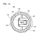
- FIG. 14 shows a fixed operating knob 228 of a first modification.
- components similar to those of the fixed operating knob 28 will be denoted by similar reference characters to the embodiment described above and redundant descriptions thereof will be omitted.
- a plurality of projecting portions 201 is formed on an upper surface of a ring member 180 of the fixed operating knob 228 or, in other words, on an end surface of the ring member 180 positioned on an opposite side to the body 12.
- the projecting portions 201 are arranged at regular intervals along a circumferential direction of the ring member 180.
- the upper ends of the projecting portions 201 are positioned on a same plane as an upper end surface of the tab 150 when the tab 150 is at a position where the tab 150 is locked by the lock member 158.
- An engaging portion 203 that engages with the projecting portions 201 is formed on the tab 150. The engaging portion 203 projects from the tab 150 toward the ring member 180.
- FIG. 15 shows a fixed operating knob 328 of a second modification.
- components similar to those of the fixed operating knob 28 will be denoted by similar reference characters to the embodiment described above and redundant descriptions thereof will be omitted.
- a plurality of projecting portions 301 is formed on an inner surface of the ring member 180 of the fixed operating knob 328.
- the projecting portions 301 are arranged at regular intervals along a circumferential direction of the ring member 180.
- An engaging portion 303 that engages with the projecting portions 301 is formed on the tab 150. The engaging portion 303 projects from the tab 150 toward the ring member 180.
- FIG. 16 shows a longitudinal sectional view of a fixed operating knob 428 of a third modification.
- components similar to those of the fixed operating knob 28 will be denoted by similar reference characters to the embodiment described above and redundant descriptions thereof will be omitted.
- the fixed operating knob 428 comprises a knob body 466, a tab 450, a lock member 458, a ring member 180, and the like.
- FIG. 16 shows a state in which the tab 450 is at a storing position.
- the tab 450 is attached to the knob body 166 via a swinging shaft 154 so as to be capable of swinging.
- the swinging shaft 154 is inserted through a torsion spring 152.
- the torsion spring 152 biases the tab 450 from the storing position toward an operating position.
- the tab 450 comprises a lock member 458.
- the lock member 458 is slidably arranged relative to the tab 450 between a lock position at which the lock member 458 engages with a depressed part 470 of the ring member 180 to lock the tab 450 to the storing position and an unlock position that disengages the locking of the tab 450.
- the lock member 458 is biased to the lock position by a spring 464.
- the lock member 458 comprises an engaging portion 458a that engages with the depressed part 470 of the ring member 180.
- the engaging portion 458a is inclined toward an outer side of the tab 450 along a direction oriented from the storing position toward the operating position.
- the plurality of depressed parts 470 that engages the lock member 458 is formed on an inner surface of the ring member 180.
- the depressed parts 470 are arranged at regular intervals along a circumferential direction of the ring member 180.
- the tab 450 swings from the storing position to the operating position due to the biasing force of the torsion spring 152. At this point, the lock member 458 is moved from the unlock position to the lock position by a biasing force of the spring 464. As the tab 450 is moved from the operating position toward the storing position, the engaging portion 458a of the lock member 458 comes into contact with an upper end (an upper end shown in FIG. 16 ) of the ring member 180. Accordingly, the lock member 458 gradually moves from the lock position to the unlock position. When the tab 450 reaches the storing position, the engaging portion 458a is inserted into the depressed parts 470 of the ring member 180. Accordingly, the tab 450 is locked at the storing position by the lock member 458.
- a similar advantageous effect to the embodiment described above can also be achieved by the fixed operating knob 428.
- the engaging portion 458a of the lock member 458 is inserted into the depressed parts 470 of the ring member 180. Accordingly, the engaging portion 458a engages with projecting portions between adjacent depressed parts 470 and prevents a rotation of the tab 450.
- the embodiment described above adopts a mechanism in which the tabs 50, 150, and 450 are locked by an engagement between the lock members 58, 158, and 458 and the tabs 50, 150, and 450 or the ring member 180.
- the locking mechanism may involve locking the tabs 50, 150, and 450 to the storing position by a magnetic force.
- lock members 58, 158, and 458 need not be biased from the unlock position toward the lock position by the springs 64, 164, and 464.
- a chain saw 10 comprising a fixed operating knob 28 that is a rotation knob and a oil cap 42 is described in the embodiment above.
- the rotation knob described in the present specification can be applied to various power tools such as a hedge cutter or a grass clipper, a hedge trimmer, a push mower, a grass cutter, and a bush cutter.
Abstract
Description
- The present specification discloses a power tool. In particular, the present specification discloses an art for enhancing operability of a rotation knob rotatably arranged on a power tool body and operated by a user.
- Japanese Patent Application Laid-open No.
2006-103301 - With the rotation knob described above, when operating the tab, the tab is constantly biased from the operating position toward the storing position. Therefore, the tab becomes unstable at the operating position and operability of the rotation knob declines.
- An art disclosed in the present application has been made in consideration of the problem described above and an object thereof is to enhance the operability of the rotation knob.
- An art disclosed in the present application is realized in a power tool. This power tool comprises a power tool body and a rotation knob rotatably arranged on the power tool body and operated by a user. The rotation knob comprises a knob body, a tab, a tab spring and a lock mechanism. The knob body is attached rotatably on the power tool body. The tab is attached on the knob body. The tab is supported being capable of swinging between an operating position projecting from the knob body and a storing position stored in one of the knob body and the power tool body. The tab spring biases the tab toward the operating position. The lock mechanism holds the tab at the storing position against the pressure of the tab spring in a case where the tab moves to the storing position.
- With this rotation knob, in a case where the rotation knob is not operated, the tab may be retained at the storing position. When rotatably operating the rotation knob, by releasing locking that comprises the lock mechanism, the tab automatically moves from the storing position to the operating position due to a biasing force of the tab spring. The user may hold the tab and operate the rotation knob. At this point, the tab is maintained at the operating position by the biasing force of the tab spring. The tab is stabilized at the operating position. Consequently, the user may easily hold the tab and operate the rotation knob. Due to the above, according to the configuration described above, operability of the rotation knob may be enhanced.
- For example, the lock mechanism may be configured so that in a case where the tab is at the storing position, the lock mechanism engages the tab to retain the tab at the storing position. Alternatively, the lock mechanism may be configured so that in the case where the tab is at the storing position, a magnetic force in an opposite direction to the biasing force of the tab spring retains the tab at the storing position.
- The lock mechanism may comprise a lock member arranged on one of the knob body and the tab. The lock member may be movably arranged between a lock position engaging with another of the knob body and the tab and an unlock position disengaging the other of the knob body and the tab in a state where the tab is located at the storing position.
- According to this configuration, when the lock member is moved from the lock position to the unlock position in a state where the tab is retained at the storing position, the tab automatically moves from the storing position to the operating position. The user need not perform troublesome operations when moving the tab to the operating position.
- In this case, the lock mechanism may further comprise a lock spring biasing the lock member toward the lock position.
- When the tab swings to the storing position and the lock member is capable of moving to the lock position, a surface of the tab may oppose a surface of one of the knob body or the power tool body with a clearance. The clearance may become gradually larger as a distance from a swinging axis of the tab increases.
- According to this configuration, when swinging the tab from the operating position toward the storing position, the tab may be swung past a position where an engagement by the lock member occurs. As a result, even if a certain amount of deformation occurs on the lock member and the like, the lock member may be reliably engaged with the knob body and the tab.
- The power tool may further comprise a ring member fixed on the power tool body and surrounding the tab and the knob body. In this case, a plurality of projecting portions may be disposed on the ring member along a circumferential direction thereof, on at least one of an end surface located opposite from the power tool body and an inner surface. The tab may comprise an engaging portion that engages with at least one of the plurality of projecting portions when the tab is positioned at the storing position.
- According to this configuration, in a case where the tab is at the storing position, the rotation knob may be prevented from rotating relative to a device.
- According to the art disclosed in the present specification, the tab may be stabilized at the operating position. As a result, the operability of the rotation knob may be enhanced.
-
FIG. 1 shows an external view of a chain saw. -
FIG. 2 shows an external view of a part of the chain saw. -
FIG. 3 shows an enlarged view of an oil cap. -
FIG. 4 shows an exploded perspective view of the oil cap. -
FIG. 5 shows a cross-sectional view of a V-V cross section ofFIG. 3 . -
FIG. 6 shows a cross-sectional view of a state in which a tab is at an operating position. -
FIG. 7 shows an enlarged view of a fixed operating knob. -
FIG. 8 shows a cross-sectional view of a VIII-VIII cross section ofFIG. 7 . -
FIG. 9 shows a cross-sectional view of a IX-IX cross section ofFIG. 7 . -
FIG. 10 shows a state in which a lock member has moved to an unlock position. -
FIG. 11 shows a state in which the tab is at the operating position. -
FIG. 12 shows a state in which the tab is halfway from the operating position to a storing position. -
FIG. 13 shows a state in which the tab is in contact with a knob body at the storing position. -
FIG. 14 shows a fixed operating knob according to a first modification. -
FIG. 15 shows a fixed operating knob according to a second modification. -
FIG. 16 shows a fixed operating knob according to a third modification. - Preferred aspects of below embodiment will be listed.
- (1) The rotation knob described above is favorably used in an oil cap of a chain saw. The chain saw comprises a chain saw body, a guide bar, a saw chain, an oil tank, and the oil cap. The guide bar is attached to the chain saw body so as to be capable of moving reciprocally relative to the chain saw body. The oil tank reserves lubricating oil that is supplied to the saw chain and the guide bar. The oil cap is rotatably arranged on the oil tank and closes an opening of the oil tank.
-
- (2) The rotation knob described above is favorably used in a fixed operating knob that fixes the guide bar to the chain saw body. The fixed operating knob is rotatably arranged on the chain saw body.
-
- (3) A swinging axis of the tab orthogonally intersects a center of rotation of the rotation knob.
-
- (4) When the tab swings from a storing position to an operating position, the tab comes into contact with a knob body and swinging of the tab is thereby stopped.
- An embodiment will now be described with reference to the drawings.
FIG. 1 shows an external view of achain saw 10.FIG. 2 shows an external view of the chain saw 10 in a state in which acover 24 and asaw chain 32 have been removed from abody 12 which will be described later. The chain saw 10 comprises thebody 12, aguide bar 30 attached to thebody 12, and thesaw chain 32. - As shown in
FIGS. 1 and2 , thebody 12 comprises amotor 16, afirst grip 14, asecond grip 18, and asprocket 38. Atrigger switch 20 that activates the chain saw 10 is arranged on thesecond grip 18. Thesprocket 38 is arranged on a side surface of thebody 12 and is rotatably supported by thebody 12. Thesprocket 38 is connected to themotor 16 and is rotatably driven by themotor 16. Themotor 16 is configured so that power is supplied to themotor 16 from abattery 22 in conjunction with an operation performed on thetrigger switch 20. Thebattery 22 is detachably attached to thebody 12. - An oil tank, not shown, is arranged on the
body 12. The oil tank stores lubricating oil to be supplied to thesaw chain 32, thesprocket 38, and the like. Anopening 12a (refer toFIG. 5 ) of the oil tank is closed by anoil cap 42, which will be described in detail later. Theoil cap 42 is rotatably attached to thebody 12. - The
guide bar 30 is attached to thebody 12. Theguide bar 30 is arranged adjacent to thesprocket 38. Theguide bar 30 is supported against thebody 12 by a supportingbolt 34 and a supportingpin 36. The supportingbolt 34 and the supportingpin 36 are fixed to thebody 12 and support theguide bar 30 so that theguide bar 30 is capable of moving reciprocally relative to thebody 12. In other words, theguide bar 30 is arranged capable of approaching/retracting from thesprocket 38. Thesaw chain 32, not shown inFIG. 2 , is provided with tension between thesprocket 38 and theguide bar 30. When an operator operates awheel 26, an adjustingpin 40 that engages with theguide bar 30 moves along a rotating shaft, not shown. Consequently, the operator can cause theguide bar 30 to approach/retract from thesprocket 38 and adjust the tension of thesaw chain 32. - A
cover 24 that covers thesprocket 38 and a fixedoperating knob 28 that is a rotation knob for fixing theguide bar 30 are arranged on a side surface of thebody 12. The fixedoperating knob 28 is rotatably attached to thebody 12. The fixedoperating knob 28 is screwed onto the supportingbolt 34 that projects from a side surface of thebody 12. When the fixedoperating knob 28 is tightened relative to the supportingbolt 34, theguide bar 30 becomes fixed to thebody 12, and when the fixedoperating knob 28 is loosened relative to the supportingbolt 34, theguide bar 30 becomes capable of moving reciprocally relative to thebody 12. Thecover 24 is fixed by the fixedoperating knob 28. Thecover 24 can be detached from thebody 12 by detaching the fixedoperating knob 28 from the supportingbolt 34. - Next, operations of the chain saw 10 will be described. When the operator turns on the
trigger switch 20, themotor 16 that is a power source rotates. Due to a rotation of themotor 16, thesprocket 38 is rotationally driven relative to thebody 12. Consequently, thesaw chain 32 that is a tool rotates along thesprocket 38 and theguide bar 30. - Next, a configuration of the
oil cap 42 will be described.FIG. 3 shows an enlarged view of theoil cap 42.FIG. 4 shows an exploded perspective view of theoil cap 42.FIG. 5 shows a cross-sectional view of a V-V cross section ofFIG. 3 . Theoil cap 42 comprises aknob body 66, atab 50, alock member 58, and the like.FIGS. 3 to 5 show a state in which thetab 50 is at a storing position.FIG. 6 shows a state in which thetab 50 is at an operating position on a same cross section as inFIG. 5 . Theknob body 66 is rotatably attached relative to thebody 12.Washers knob body 66 on a side of theopening 12a of the oil tank. Thewashers knob body 66 and a ring-like cap 74. Theknob body 66 has an opposingsurface 66a that opposes aside surface 50b of thetab 50 on a side of theknob body 66 when thetab 50 is at the storing position, which will be described later, and a contactingsurface 66b that comes into contact with thetab 50 when thetab 50 is at the operating position, which will be described later. - The
tab 50 is attached to theknob body 66 and is capable of swinging. Anopening 50a is formed at a center of swinging of thetab 50. A swinging shaft (axis) 54 is inserted through theopening 50a. The swingingshaft 54 is arranged at a position at which the swingingshaft 54 orthogonally intersects a center axis of rotation of theoil cap 42. The swingingshaft 54 is inserted through atorsion spring 52. Thetorsion spring 52 biases thetab 50 from the storing position toward the operating position. Aclearance 76 is provided between theside surface 50b of thetab 50 on the side of theknob body 66 and the opposingsurface 66a when thetab 50 is at a position where thetab 50 is locked by thelock member 58. Theclearance 76 gradually becomes greater as a distance from the swingingshaft 54 of thetab 50 becomes greater. - The
tab 50 is locked to the storing position by thelock member 58. Thelock member 58 is slidably attached to theknob body 66. Thelock member 58 is slidably arranged relative to theknob body 66 between a lock position that locks thetab 50 to the storing position as shown inFIGS. 3 and5 and an unlock position that disengages the locking of thetab 50 as shown inFIG. 6 . Thelock member 58 is biased to the lock position by aspring 64. Thelock member 58 slides along a fixedguide member 56 of theknob body 66. Thelock member 58 has an engagingportion 60 that engages with an engagingportion 50c of thetab 50 when thetab 50 is at the storing position. An inclined surface 59 (anupper surface 59 inFIG. 5 ) of the engagingportion 60 is inclined toward theknob body 66. - The
tab 50 is locked at the storing position by engaging with the engagingportion 60 of thelock member 58 at the lock position. The operator hooks adepressed part 62 of thelock member 58 with a finger to move thelock member 58 from the lock position to the unlock position shown inFIG. 6 . When thelock member 58 is moved to the unlock position, thetab 50 swings toward the operating position due to a biasing force of thetorsion spring 52. Swinging of thetab 50 is restricted as thetab 50 comes into contact with the contactingsurface 66b of theknob body 66. When the operator releases thelock member 58, thelock member 58 moves from the unlock position to the lock position due to a biasing force of thespring 64. When thetab 50 is at the operating position, thetab 50 projects from theknob body 66. Consequently, the operator can hold thetab 50 and rotationally move theoil cap 42 relative to thebody 12. - When the
tab 50 is pressed from the operating position toward the storing position, thetab 50 swings relative to theknob body 66. As thetab 50 moves from the operating position to the storing position, theinclined surface 59 of thelock member 58 is pressed by the engagingportion 50c of thetab 50 and thelock member 58 is gradually moved toward the unlock position. When thetab 50 moves to the storing position, the contact between theinclined surface 59 of thelock member 58 and the engagingportion 50c is released. In other words, thelock member 58 is released from a pressing force from thetab 50. As a result, thelock member 58 is moved to the lock position by a biasing force of thespring 64. Thetab 50 goes beyond a position at which thetab 50 is locked by the lock member 58 (a position of thetab 50 inFIG. 5 ) and moves until theside surface 50b of thetab 50 comes into contact with the opposingsurface 66a of theknob body 66. When the operator releases the finger from thetab 50, thetab 50 is moved by a biasing force of thetorsion spring 52 to a position at which thetab 50 engages with thelock member 58 as shown inFIG. 5 . Thetab 50 engages with, and is locked by, thelock member 58. - Next, a configuration of the fixed
operating knob 28 will be described.FIG. 7 shows an enlarged view of the fixedoperating knob 28.FIG. 8 shows a cross-sectional view of a VIII-VIII cross section ofFIG. 7 .FIG. 9 shows a cross-sectional view of a IX-IX cross section ofFIG. 7 . The fixedoperating knob 28 comprises aknob body 166, atab 150, alock member 158, aring member 180, anut 184, and the like.FIGS. 7 to 9 show a state in which thetab 150 is at the storing position. Theknob body 166 has an opposingsurface 166a that opposes aside surface 150a of thetab 150 on a side of the knob body when thetab 150 is at the storing position and a contacting surface (not shown) that comes into contact with thetab 150 when thetab 150 is at the operating position, which will be described later. The fixedoperating knob 28 is attached to thebody 12 by screwing thenut 184 into the supportingbolt 34. - The
tab 150 is attached to theknob body 166 via a swinging shaft (axis) 154 and is capable of swinging. The swingingshaft 154 is arranged at a position at which the swingingshaft 154 orthogonally intersects a center axis of rotation of the fixedoperating knob 28 or, in other words, a position at which the swingingshaft 154 orthogonally intersects an axial direction of the supportingbolt 34. The swingingshaft 154 is inserted through atorsion spring 152. Thetorsion spring 152 biases thetab 150 from the storing position toward the operating position. Aclearance 176 is provided between theside surface 150a of thetab 150 on the side of theknob body 166 and the opposingsurface 166a when thetab 150 is at a position where thetab 150 is locked by thelock member 158. Theclearance 176 gradually becomes greater as a distance from the swingingshaft 154 of thetab 150 becomes greater. - The
tab 150 is locked to the storing position by thelock member 158. Thelock member 158 is slidably attached to theknob body 166. Thelock member 158 is slidably arranged between a lock position that locks thetab 150 to the storing position as shown inFIGS. 7 and8 and an unlock position (refer toFIG. 10 ) that disengages the locking of thetab 150. Thelock member 158 is biased to the lock position by aspring 164. Thelock member 158 slides along a fixedguide member 156 of theknob body 166. Thelock member 158 has an engagingportion 160 that engages with an engagingportion 150b of thetab 150 when thetab 150 is at the storing position. An inclined surface 159 (anupper surface 159 inFIG. 8 ) of the engagingportion 160 is inclined toward theknob body 166. -
FIG. 10 shows a state in which thelock member 158 has moved to an unlock position on the VIII-VIII cross section ofFIG. 7 . When thelock member 158 is moved to the unlock position, the engagement between thetab 150 and thelock member 158 is released. As a result, thetab 150 swings toward the operating position due to a biasing force of thetorsion spring 152. Swinging of thetab 150 is restricted as thetab 150 comes into contact with the contacting surface of theknob body 166.FIG. 11 shows a state in which thetab 150 is at the operating position. When thetab 150 is at the operating position, thetab 150 projects from theknob body 166. Consequently, the operator can hold thetab 150 and rotationally move the fixedoperating knob 28 relative to thebody 12. Thelock member 158 is moved from the unlock position to the lock position by a biasing force of thespring 164. - When the
tab 150 is pressed from the operating position toward the storing position, thetab 150 swings relative to theknob body 166. As shown inFIG. 12 , as thetab 150 moves from the operating position to the storing position, theinclined surface 159 of thelock member 158 is pressed by the engagingportion 150b of thetab 150 and thelock member 158 is gradually moved toward the unlock position. When thetab 150 moves to the storing position, the contact between theinclined surface 159 of thelock member 158 and the engagingportion 150b is released. In other words, thelock member 158 is released from a pressing force from thetab 150. As a result, thelock member 158 is moved to the lock position by a biasing force of thespring 164. As shown inFIG. 13 , thetab 150 goes beyond a position at which thetab 150 is locked by the lock member 158 (a position of thetab 150 inFIG. 8 ) and moves until theside surface 150a of thetab 150 comes into contact with the opposingsurface 166a of theknob body 166. When the operator releases thetab 150, thetab 150 is moved by a biasing force of thetorsion spring 152 to a position at which thetab 150 engages with thelock member 158 as shown inFIG. 8 . Thetab 150 engages with, and is locked by, thelock member 158. - With the fixed
operating knob 28 according to the present embodiment, locking of thetab 150 is released by moving thelock member 158 from the lock position to the unlock position. Accordingly, thetab 150 is moved from the storing position to the operating position by the biasing force of thetorsion spring 152.
When thetab 150 is at the operating position, thetab 150 is brought into contact with theknob body 166 by the biasing force of thetorsion spring 152. As a result, thetab 150 stabilizes at the operating position. Accordingly, operability of thetab 150 is enhanced.
Similarly, with theoil cap 42, locking of thetab 50 is released by moving thelock member 58 from the lock position to the unlock position and thetab 50 is moved from the storing position to the operating position. When thetab 50 is at the operating position, thetab 50 is brought into contact with theknob body 66 by the biasing force of thetorsion spring 52. As a result, thetab 50 stabilizes at the operating position. Accordingly, operability of thetab 50 is enhanced. - The
lock member 158 is biased from the unlock position toward the lock position by thespring 164. As thetab 150 swings from the operating position toward the storing position, thetab 150 comes into contact with thelock member 158 and moves thelock member 158 from the lock position to the unlock position. When thetab 150 is moved to the storing position, thelock member 158 is moved from the unlock position to the lock position by a biasing force of thespring 164. As a result, when storing thetab 150 into the storing position, thetab 150 is automatically locked at the storing position without having to operate thelock member 158 and simply by moving thetab 150 from the operating position to the storing position.
Similarly, with theoil cap 42, when thetab 50 swings from the operating position to the storing position, thelock member 58 is moved from the lock position to the unlock position. When thetab 50 is moved to the storing position, thelock member 58 is moved from the unlock position to the lock position by the biasing force of thespring 64. As a result, when storing thetab 50 into the storing position, thetab 50 is automatically locked at the storing position without having to operate thelock member 58 and simply by moving thetab 50 from the operating position to the storing position. - With the fixed
operating knob 28, aclearance 176 is provided between theside surface 150a of thetab 150 and the opposingsurface 166a of theknob body 166 when thetab 150 is at the position where thetab 150 is locked by thelock member 158. In this configuration, when thetab 150 swings from the operating position to the storing position, thetab 150 goes beyond the position at which thetab 150 is locked by thelock member 158 and swings to a position at which thetab 150 comes into contact with the opposingsurface 166a. Accordingly, as thelock member 158 moves from the unlock position to the lock position, a clearance can be formed between the engagingportion 160 of thelock member 158 and the engagingportion 150b of thetab 150. Therefore, the engagingportion 160 and the engagingportion 150b need no longer be fabricated with high precision. - Modifications of the fixed
operating knob 28 according to the embodiment above will now be described with reference to the drawings.
FIG. 14 shows a fixedoperating knob 228 of a first modification. InFIG. 14 and hereinafter, components similar to those of the fixedoperating knob 28 will be denoted by similar reference characters to the embodiment described above and redundant descriptions thereof will be omitted. - A plurality of projecting
portions 201 is formed on an upper surface of aring member 180 of the fixedoperating knob 228 or, in other words, on an end surface of thering member 180 positioned on an opposite side to thebody 12. The projectingportions 201 are arranged at regular intervals along a circumferential direction of thering member 180. The upper ends of the projectingportions 201 are positioned on a same plane as an upper end surface of thetab 150 when thetab 150 is at a position where thetab 150 is locked by thelock member 158. An engagingportion 203 that engages with the projectingportions 201 is formed on thetab 150. The engagingportion 203 projects from thetab 150 toward thering member 180. - With the fixed
operating knob 228, when thetab 150 is at a storing position, an engagement between the projectingportions 201 of thering member 180 and the engagingportion 203 of thetab 150 can prevent thetab 150 from rotating relative to thering member 180. Accordingly, wobbling of theguide bar 30 due to relaxing of a binding force between anut 184 of the fixedoperating knob 228 and the supportingbolt 34 of thebody 12 can be prevented. -
FIG. 15 shows a fixedoperating knob 328 of a second modification. InFIG. 15 and hereinafter, components similar to those of the fixedoperating knob 28 will be denoted by similar reference characters to the embodiment described above and redundant descriptions thereof will be omitted. - A plurality of projecting
portions 301 is formed on an inner surface of thering member 180 of the fixedoperating knob 328. The projectingportions 301 are arranged at regular intervals along a circumferential direction of thering member 180. An engagingportion 303 that engages with the projectingportions 301 is formed on thetab 150. The engagingportion 303 projects from thetab 150 toward thering member 180. - With the fixed
operating knob 328, in the same manner as the fixedoperating knob 228, when thetab 150 is at a storing position, an engagement between the projectingportions 301 of thering member 180 and the engagingportion 303 of thetab 150 can prevent thetab 150 from rotating relative to thering member 180. -
FIG. 16 shows a longitudinal sectional view of a fixedoperating knob 428 of a third modification. InFIG. 15 and hereinafter, components similar to those of the fixedoperating knob 28 will be denoted by similar reference characters to the embodiment described above and redundant descriptions thereof will be omitted. - The fixed
operating knob 428 comprises aknob body 466, atab 450, alock member 458, aring member 180, and the like.FIG. 16 shows a state in which thetab 450 is at a storing position.
Thetab 450 is attached to theknob body 166 via a swingingshaft 154 so as to be capable of swinging. The swingingshaft 154 is inserted through atorsion spring 152. Thetorsion spring 152 biases thetab 450 from the storing position toward an operating position. - The
tab 450 comprises alock member 458. Thelock member 458 is slidably arranged relative to thetab 450 between a lock position at which thelock member 458 engages with adepressed part 470 of thering member 180 to lock thetab 450 to the storing position and an unlock position that disengages the locking of thetab 450. Thelock member 458 is biased to the lock position by aspring 464.
Thelock member 458 comprises an engagingportion 458a that engages with thedepressed part 470 of thering member 180. The engagingportion 458a is inclined toward an outer side of thetab 450 along a direction oriented from the storing position toward the operating position. The plurality ofdepressed parts 470 that engages thelock member 458 is formed on an inner surface of thering member 180. Thedepressed parts 470 are arranged at regular intervals along a circumferential direction of thering member 180. - When the
lock member 458 is moved from the lock position to the unlock position, thetab 450 swings from the storing position to the operating position due to the biasing force of thetorsion spring 152. At this point, thelock member 458 is moved from the unlock position to the lock position by a biasing force of thespring 464. As thetab 450 is moved from the operating position toward the storing position, the engagingportion 458a of thelock member 458 comes into contact with an upper end (an upper end shown inFIG. 16 ) of thering member 180. Accordingly, thelock member 458 gradually moves from the lock position to the unlock position. When thetab 450 reaches the storing position, the engagingportion 458a is inserted into thedepressed parts 470 of thering member 180. Accordingly, thetab 450 is locked at the storing position by thelock member 458. - A similar advantageous effect to the embodiment described above can also be achieved by the fixed
operating knob 428. The engagingportion 458a of thelock member 458 is inserted into thedepressed parts 470 of thering member 180. Accordingly, the engagingportion 458a engages with projecting portions between adjacentdepressed parts 470 and prevents a rotation of thetab 450. - Specific embodiment of the present teachings is described above, but this merely illustrates some representative possibilities for utilizing the teachings and does not restrict the claims thereof. The subject matter set forth in the claims includes variations and modifications of the specific examples set forth above.
- For example, the embodiment described above adopts a mechanism in which the
tabs lock members tabs ring member 180. However, for example, the locking mechanism may involve locking thetabs - In addition, the
lock members springs - A chain saw 10 comprising a fixed
operating knob 28 that is a rotation knob and aoil cap 42 is described in the embodiment above. However, in addition to the chain saw 10, the rotation knob described in the present specification can be applied to various power tools such as a hedge cutter or a grass clipper, a hedge trimmer, a push mower, a grass cutter, and a bush cutter. - The technical elements disclosed in the specification or the drawings may be utilized separately or in all types of combinations, and are not limited to the combinations set forth in the claims at the time of filing of the application. Furthermore, the subject matter disclosed herein may be utilized to simultaneously achieve a plurality of objects or to only achieve one object.
Claims (5)
- A power tool comprising:a power tool body; anda rotation knob rotatably arranged on the power tool body and operated by a user,wherein the rotation knob comprises:a knob body attached rotatably on the power tool body;a tab attached on the knob body and capable of swinging between an operating position projecting from the knob body and a storing position stored in one of the knob body and the power tool body;a tab spring biasing the tab toward the operating position; anda lock mechanism holding the tab at the storing position against the pressure of the tab spring in a case where the tab moves to the storing position.
- The power tool as in claim 1, wherein
the lock mechanism comprises a lock member arranged on one of the knob body and the tab, and
the lock member is movably arranged between a lock position engaging with another of the knob body and the tab and an unlock position disengaging the other of the knob body and the tab in a state where the tab is located at the storing position. - The power tool as in claim 2, wherein
the lock mechanism further comprises a lock spring biasing the lock member toward the lock position. - The power tool as in claim 2 or 3, wherein
when the tab swings to the storing position and the lock member is capable of moving to the lock position, a surface of the tab opposes a surface of one of the knob body or the power tool body with a clearance, and
the clearance becomes gradually larger as a distance from a swinging axis of the tab increases. - The power tool as in any one of claims 1 to 4, further comprising:a ring member fixed on the power tool body and surrounding the tab and the knob body,wherein a plurality of projecting portions is disposed on the ring member along a circumferential direction thereof, on at least one of an end surface located opposite from the power tool body and an inner surface, andthe tab comprises an engaging portion that engages with at least one of the plurality of projecting portions when the tab is positioned at the storing position.
Applications Claiming Priority (2)
| Application Number | Priority Date | Filing Date | Title |
|---|---|---|---|
| JP2009122279A JP5396149B2 (en) | 2009-05-20 | 2009-05-20 | Power tools |
| PCT/JP2010/056243 WO2010134392A1 (en) | 2009-05-20 | 2010-04-06 | Powered tool |
Publications (3)
| Publication Number | Publication Date |
|---|---|
| EP2433754A1 true EP2433754A1 (en) | 2012-03-28 |
| EP2433754A4 EP2433754A4 (en) | 2013-12-18 |
| EP2433754B1 EP2433754B1 (en) | 2016-05-11 |
Family
ID=43126080
Family Applications (1)
| Application Number | Title | Priority Date | Filing Date |
|---|---|---|---|
| EP10777627.0A Active EP2433754B1 (en) | 2009-05-20 | 2010-04-06 | Powered tool |
Country Status (6)
| Country | Link |
|---|---|
| US (1) | US8931575B2 (en) |
| EP (1) | EP2433754B1 (en) |
| JP (1) | JP5396149B2 (en) |
| CN (1) | CN102802877B (en) |
| RU (1) | RU2494856C2 (en) |
| WO (1) | WO2010134392A1 (en) |
Cited By (2)
| Publication number | Priority date | Publication date | Assignee | Title |
|---|---|---|---|---|
| WO2014001065A3 (en) * | 2012-06-28 | 2014-03-20 | Robert Bosch Gmbh | Tool coupling device |
| DE102014004062A1 (en) * | 2013-03-29 | 2015-07-02 | Makita Corporation | Guide rod attachment device for a chain saw |
Families Citing this family (8)
| Publication number | Priority date | Publication date | Assignee | Title |
|---|---|---|---|---|
| JP5314496B2 (en) | 2009-05-20 | 2013-10-16 | 株式会社マキタ | Chainsaw |
| JP5486214B2 (en) * | 2009-05-20 | 2014-05-07 | 株式会社マキタ | Power tools |
| JP5396149B2 (en) | 2009-05-20 | 2014-01-22 | 株式会社マキタ | Power tools |
| WO2012144942A1 (en) * | 2011-04-21 | 2012-10-26 | Husqvarna Ab | A clamping assembly for a chainsaw |
| AU2012316766B2 (en) | 2011-09-29 | 2015-05-28 | Husqvarna Ab | Quick-change blade system |
| CN103009438B (en) * | 2012-12-05 | 2015-07-15 | 南京德朔实业有限公司 | Chain saw |
| DE102013003850A1 (en) * | 2013-03-06 | 2014-09-25 | Andreas Stihl Ag & Co. Kg | Hand-held implement with a tensioning device for a chain |
| US20210405679A1 (en) * | 2020-06-25 | 2021-12-30 | Ivan Ferrer | Aircraft sun visor thumb knob attachment device |
Citations (1)
| Publication number | Priority date | Publication date | Assignee | Title |
|---|---|---|---|---|
| EP1619004A1 (en) * | 2004-07-21 | 2006-01-25 | Electrolux Home Products, Inc. | Rotatable knob with cam-operated locking mechanism for a chain saw tensioning arrangement |
Family Cites Families (62)
| Publication number | Priority date | Publication date | Assignee | Title |
|---|---|---|---|---|
| US1208356A (en) | 1916-01-25 | 1916-12-12 | William J Nesbitt | Feeding-mechanism gearing. |
| US1865764A (en) | 1930-09-26 | 1932-07-05 | Gen Lab Inc | Container stopper |
| US2297378A (en) | 1941-07-31 | 1942-09-29 | Nat Pressure Cooker Co | Pressure control and indicator gauge |
| US2444132A (en) | 1944-04-13 | 1948-06-29 | Mall Tool Company | Chain saw machine |
| US2491543A (en) | 1948-05-07 | 1949-12-20 | Alfonso Joseph | Release nut |
| US2533771A (en) | 1948-07-09 | 1950-12-12 | Pennsylvania Furnace And Iron | Vented closure for milk tank manholes |
| BE626501A (en) | 1961-12-29 | |||
| US3194284A (en) | 1963-06-05 | 1965-07-13 | Charles M Walker | Tension adjusting means for chain saws |
| US3557986A (en) | 1969-02-24 | 1971-01-26 | William T Poole Jr | Pressurizing closure device |
| US3621876A (en) | 1970-01-19 | 1971-11-23 | Robert K Campbell | Self-sealing chalk valve |
| JPS5032516A (en) | 1973-07-25 | 1975-03-29 | ||
| US3967645A (en) | 1974-01-25 | 1976-07-06 | Urocare Products, Inc. | Check valve for urine collection device |
| US3866320A (en) | 1974-03-04 | 1975-02-18 | Textron Inc | Guide bar adjustment for chain saw |
| JPS52131870A (en) | 1976-04-27 | 1977-11-05 | Iony Kk | Stone sorting device for rice pearling factory |
| SU769152A1 (en) * | 1977-01-03 | 1980-10-07 | Предприятие П/Я А-3697 | Rotation speed limiter |
| US4165816A (en) | 1978-04-10 | 1979-08-28 | Dapco Industries | Vent cap |
| JPS55163567A (en) | 1979-06-05 | 1980-12-19 | Kogyo Gijutsuin | Auxiliary device for blind person handwriting learning |
| JPS5652653A (en) | 1979-10-05 | 1981-05-11 | Toyota Motor Corp | Stepless transmission |
| US4271976A (en) | 1979-11-13 | 1981-06-09 | E. Edelmann & Co. | Combination pressure release cooling cap and recovery of coolant |
| US4458711A (en) | 1981-03-02 | 1984-07-10 | Justrite Manufacturing Company | Vent valve |
| JPS58192003A (en) | 1982-04-28 | 1983-11-09 | フアイバ−グラス・カナダ・インコ−ポレ−テツド | Optical fiber transmission cable, reinforcing material and manufacture thereof |
| US4524805A (en) | 1983-07-08 | 1985-06-25 | Hoffman Allan C | Normally closed duckbill valve and method of manufacture |
| JPS60116974A (en) | 1983-11-29 | 1985-06-24 | Toyoda Gosei Co Ltd | Valve-equipped cap |
| JPS6225180A (en) | 1985-07-24 | 1987-02-03 | Shin Etsu Chem Co Ltd | Composition for preventing bill sticking |
| JPH0727122Y2 (en) | 1986-12-17 | 1995-06-21 | 株式会社共立 | Chainsaw saw chain tensioner |
| US4747501A (en) | 1987-07-08 | 1988-05-31 | National Plastics Limited | Container closure method |
| FR2638563B1 (en) * | 1988-10-27 | 1990-12-14 | Telemecanique Electrique | SAFETY DEVICE FOR A SWITCHING APPARATUS MADE BY ASSEMBLING A PLURALITY OF REMOVABLE MODULAR ELEMENTS |
| US4896789A (en) | 1989-02-17 | 1990-01-30 | Tecumseh Products Company | Anti-leak fuel cap liner |
| US4987740A (en) | 1989-04-03 | 1991-01-29 | General Motors Corporation | Assured venting master cylinder diaphragm apparatus and method |
| CN2071109U (en) | 1990-09-11 | 1991-02-13 | 赵文才 | Quick adjustable wrench |
| SE467488B (en) | 1990-12-10 | 1992-07-27 | Sandvik Ab | FACTS FOR CASE |
| DE19523645A1 (en) | 1995-06-29 | 1997-01-02 | Stihl Maschf Andreas | Valve for aerating and ventilating vehicle fuel tank of hand-held work tools |
| FR2743786B1 (en) | 1996-01-23 | 1999-04-16 | Stihl Maschf Andreas | PLUG FOR A FILLING OPENING OF A FUEL TANK |
| JPH10286802A (en) | 1997-02-14 | 1998-10-27 | Kioritz Corp | Saw chain stretching device for chain saw |
| US6092551A (en) | 1998-05-19 | 2000-07-25 | Chesebrough-Pond's Usa Co., Division Of Conopco, Inc. | Duckbill valve |
| US6237228B1 (en) | 1999-07-20 | 2001-05-29 | Andrew Moody | Apparatus for adjusting tightness of a chain saw cutting element |
| US6585005B1 (en) | 1999-08-18 | 2003-07-01 | Red Valve Co., Inc. | Reinforced tide gate valve |
| US6619497B2 (en) | 2001-09-26 | 2003-09-16 | Girard Equipment Co. | Apparatus for venting a container containing fluid |
| US6745914B2 (en) | 2001-11-26 | 2004-06-08 | Toyoda Gosei., Ltd. | Cap device |
| GB0214772D0 (en) * | 2002-06-26 | 2002-08-07 | Black & Decker Inc | Hammer |
| US6795987B2 (en) | 2002-09-17 | 2004-09-28 | Kenneth R. Cornwall | Trap guard device |
| US7185437B2 (en) | 2002-11-15 | 2007-03-06 | Carlton Company | Chainsaw bar tensioning apparatus |
| CN1750993A (en) | 2003-02-19 | 2006-03-22 | 可口可乐公司 | System and method for aseptic filling of packages with liquid products |
| SE0300611D0 (en) | 2003-03-06 | 2003-03-06 | Electrolux Ab | Chain saw tensioning device |
| JP4584143B2 (en) | 2003-05-20 | 2010-11-17 | ハスクバーナ・ゼノア株式会社 | Auto chain tensioner |
| US20050092156A1 (en) * | 2003-10-29 | 2005-05-05 | Credo Technology Corporation | Scroll collar for reciprocating saw |
| DE10353737B4 (en) | 2003-11-17 | 2007-06-28 | Mogatec Moderne Gartentechnik Gmbh | Chain tensioning device for a motor chain saw |
| US6877233B1 (en) | 2004-01-08 | 2005-04-12 | Electrolux Home Products, Inc. | Chain saw adjuster mechanism with locking teeth |
| DE102004025951A1 (en) * | 2004-05-27 | 2005-12-22 | Robert Bosch Gmbh | Hand tool, in particular drill and / or percussion hammer |
| US7107689B2 (en) * | 2004-10-08 | 2006-09-19 | Husqvarna Outdoor Products Inc. | Bar knob with integrated lock |
| JP2006138331A (en) | 2004-11-10 | 2006-06-01 | Keeper Co Ltd | Breather valve seal for liquid tank |
| EP1674207B1 (en) * | 2004-12-23 | 2008-12-10 | BLACK & DECKER INC. | Power tool |
| US7481000B2 (en) | 2005-01-10 | 2009-01-27 | Husqvarna Outdoor Products Inc. | Chainsaw bar adjustment assembly with breakaway adjustment pin |
| US7155832B2 (en) | 2005-03-01 | 2007-01-02 | Husqvarna Outdoor Products Inc. | Chain saw with tool-less chain tensioner and guide bar lock |
| US7743513B1 (en) | 2006-10-31 | 2010-06-29 | Mtd Products Inc | Chainsaw tensioning device |
| CN200977856Y (en) | 2006-11-09 | 2007-11-21 | 马云峰 | Unidirectional conducting oil box cover |
| DE202006019362U1 (en) | 2006-12-22 | 2007-10-11 | Chung Lee, Hsin-Chih, Chungli City | Keyless adjustment mechanism for a chain saw |
| FR2912949B1 (en) | 2007-02-26 | 2009-04-24 | Pellenc Sa | CHAIN SAW HAVING A DEVICE FOR ADJUSTING THE VOLTAGE OF THE CUTTING CHAIN |
| JP5053066B2 (en) | 2007-03-15 | 2012-10-17 | 株式会社リコー | Inner and outer plugs for toner containers |
| US20090241353A1 (en) | 2008-04-01 | 2009-10-01 | Scott William Ericson | Toolless Apparatus for Guide Bar for Chain Saw |
| FR2940603B1 (en) | 2008-12-30 | 2011-01-28 | Seb Sa | PRESSURIZED COOKING APPARATUS PROVIDED WITH AN ASYMMETRICALLY OPERATED LOCKING / UNLOCKING CONTROL MEMBER |
| JP5396149B2 (en) | 2009-05-20 | 2014-01-22 | 株式会社マキタ | Power tools |
-
2009
- 2009-05-20 JP JP2009122279A patent/JP5396149B2/en active Active
-
2010
- 2010-04-06 WO PCT/JP2010/056243 patent/WO2010134392A1/en active Application Filing
- 2010-04-06 CN CN201080032513.0A patent/CN102802877B/en active Active
- 2010-04-06 EP EP10777627.0A patent/EP2433754B1/en active Active
- 2010-04-06 RU RU2011151825/02A patent/RU2494856C2/en active
- 2010-04-06 US US13/320,705 patent/US8931575B2/en active Active
Patent Citations (1)
| Publication number | Priority date | Publication date | Assignee | Title |
|---|---|---|---|---|
| EP1619004A1 (en) * | 2004-07-21 | 2006-01-25 | Electrolux Home Products, Inc. | Rotatable knob with cam-operated locking mechanism for a chain saw tensioning arrangement |
Non-Patent Citations (1)
| Title |
|---|
| See also references of WO2010134392A1 * |
Cited By (4)
| Publication number | Priority date | Publication date | Assignee | Title |
|---|---|---|---|---|
| WO2014001065A3 (en) * | 2012-06-28 | 2014-03-20 | Robert Bosch Gmbh | Tool coupling device |
| DE102014004062A1 (en) * | 2013-03-29 | 2015-07-02 | Makita Corporation | Guide rod attachment device for a chain saw |
| US9676115B2 (en) | 2013-03-29 | 2017-06-13 | Makita Corporation | Guide bar fastening device for chain saw |
| DE102014004062B4 (en) * | 2013-03-29 | 2017-07-13 | Makita Corporation | Guide rod attachment device for a chain saw |
Also Published As
| Publication number | Publication date |
|---|---|
| EP2433754B1 (en) | 2016-05-11 |
| CN102802877B (en) | 2014-11-26 |
| EP2433754A4 (en) | 2013-12-18 |
| WO2010134392A1 (en) | 2010-11-25 |
| US20120061115A1 (en) | 2012-03-15 |
| JP5396149B2 (en) | 2014-01-22 |
| CN102802877A (en) | 2012-11-28 |
| RU2011151825A (en) | 2013-06-27 |
| JP2010269393A (en) | 2010-12-02 |
| RU2494856C2 (en) | 2013-10-10 |
| US8931575B2 (en) | 2015-01-13 |
Similar Documents
| Publication | Publication Date | Title |
|---|---|---|
| EP2433754B1 (en) | Powered tool | |
| EP2433766B1 (en) | Chain saw | |
| AU2003262485B2 (en) | Toolless blade holder for a reciprocating tool | |
| US8784164B2 (en) | Power tool with a shield | |
| EP3296062B1 (en) | Multipurpose tool having accessible tool members | |
| EP2688715B1 (en) | Hand held power tool with locking rotatable handle | |
| US20050092792A1 (en) | Power tool | |
| EP3192620B1 (en) | Miter saw | |
| EP2452781B1 (en) | Staple gun wire guide | |
| US20070022852A1 (en) | Retractor for circular saw lower safety-guard | |
| JP2007152081A (en) | Folding device | |
| WO2014000950A1 (en) | Tool-coupling device | |
| JP2011255449A (en) | Blade mounting device in reciprocating cutting tool | |
| JP2001287201A (en) | Portable power tool | |
| RU2009107893A (en) | CARTRIDGE FOR FASTENING THE WORKING BODY OF THE HAND MACHINE | |
| US20080008523A1 (en) | Retaining Device Of A Tool Cotter For A Percussive Demolition Apparatus | |
| JP4596368B2 (en) | Portable cutting machine | |
| JP4610270B2 (en) | Mower | |
| EP2554313B1 (en) | Lock for power tool | |
| EP3520942B1 (en) | Jigsaw with blade clamping mechanism | |
| JP4450390B2 (en) | Tool holding device for impact tools. | |
| JP6261254B2 (en) | Torque Wrench | |
| JP2014091225A (en) | Chain saw | |
| NZ529752A (en) | Toolless blade holder for a reciprocating tool |
Legal Events
| Date | Code | Title | Description |
|---|---|---|---|
| PUAI | Public reference made under article 153(3) epc to a published international application that has entered the european phase |
Free format text: ORIGINAL CODE: 0009012 |
|
| 17P | Request for examination filed |
Effective date: 20111107 |
|
| AK | Designated contracting states |
Kind code of ref document: A1 Designated state(s): AT BE BG CH CY CZ DE DK EE ES FI FR GB GR HR HU IE IS IT LI LT LU LV MC MK MT NL NO PL PT RO SE SI SK SM TR |
|
| DAX | Request for extension of the european patent (deleted) | ||
| A4 | Supplementary search report drawn up and despatched |
Effective date: 20131114 |
|
| RIC1 | Information provided on ipc code assigned before grant |
Ipc: B25F 5/00 20060101AFI20131108BHEP Ipc: B27B 17/14 20060101ALI20131108BHEP Ipc: B27B 17/00 20060101ALI20131108BHEP |
|
| GRAP | Despatch of communication of intention to grant a patent |
Free format text: ORIGINAL CODE: EPIDOSNIGR1 |
|
| INTG | Intention to grant announced |
Effective date: 20160118 |
|
| GRAS | Grant fee paid |
Free format text: ORIGINAL CODE: EPIDOSNIGR3 |
|
| GRAA | (expected) grant |
Free format text: ORIGINAL CODE: 0009210 |
|
| AK | Designated contracting states |
Kind code of ref document: B1 Designated state(s): AT BE BG CH CY CZ DE DK EE ES FI FR GB GR HR HU IE IS IT LI LT LU LV MC MK MT NL NO PL PT RO SE SI SK SM TR |
|
| REG | Reference to a national code |
Ref country code: GB Ref legal event code: FG4D |
|
| REG | Reference to a national code |
Ref country code: CH Ref legal event code: EP |
|
| REG | Reference to a national code |
Ref country code: AT Ref legal event code: REF Ref document number: 798267 Country of ref document: AT Kind code of ref document: T Effective date: 20160515 |
|
| REG | Reference to a national code |
Ref country code: IE Ref legal event code: FG4D |
|
| REG | Reference to a national code |
Ref country code: DE Ref legal event code: R096 Ref document number: 602010033328 Country of ref document: DE |
|
| REG | Reference to a national code |
Ref country code: LT Ref legal event code: MG4D |
|
| REG | Reference to a national code |
Ref country code: NL Ref legal event code: MP Effective date: 20160511 |
|
| PG25 | Lapsed in a contracting state [announced via postgrant information from national office to epo] |
Ref country code: NL Free format text: LAPSE BECAUSE OF FAILURE TO SUBMIT A TRANSLATION OF THE DESCRIPTION OR TO PAY THE FEE WITHIN THE PRESCRIBED TIME-LIMIT Effective date: 20160511 Ref country code: FI Free format text: LAPSE BECAUSE OF FAILURE TO SUBMIT A TRANSLATION OF THE DESCRIPTION OR TO PAY THE FEE WITHIN THE PRESCRIBED TIME-LIMIT Effective date: 20160511 Ref country code: NO Free format text: LAPSE BECAUSE OF FAILURE TO SUBMIT A TRANSLATION OF THE DESCRIPTION OR TO PAY THE FEE WITHIN THE PRESCRIBED TIME-LIMIT Effective date: 20160811 Ref country code: LT Free format text: LAPSE BECAUSE OF FAILURE TO SUBMIT A TRANSLATION OF THE DESCRIPTION OR TO PAY THE FEE WITHIN THE PRESCRIBED TIME-LIMIT Effective date: 20160511 |
|
| REG | Reference to a national code |
Ref country code: AT Ref legal event code: MK05 Ref document number: 798267 Country of ref document: AT Kind code of ref document: T Effective date: 20160511 |
|
| PG25 | Lapsed in a contracting state [announced via postgrant information from national office to epo] |
Ref country code: PT Free format text: LAPSE BECAUSE OF FAILURE TO SUBMIT A TRANSLATION OF THE DESCRIPTION OR TO PAY THE FEE WITHIN THE PRESCRIBED TIME-LIMIT Effective date: 20160912 Ref country code: HR Free format text: LAPSE BECAUSE OF FAILURE TO SUBMIT A TRANSLATION OF THE DESCRIPTION OR TO PAY THE FEE WITHIN THE PRESCRIBED TIME-LIMIT Effective date: 20160511 Ref country code: ES Free format text: LAPSE BECAUSE OF FAILURE TO SUBMIT A TRANSLATION OF THE DESCRIPTION OR TO PAY THE FEE WITHIN THE PRESCRIBED TIME-LIMIT Effective date: 20160511 Ref country code: GR Free format text: LAPSE BECAUSE OF FAILURE TO SUBMIT A TRANSLATION OF THE DESCRIPTION OR TO PAY THE FEE WITHIN THE PRESCRIBED TIME-LIMIT Effective date: 20160812 Ref country code: SE Free format text: LAPSE BECAUSE OF FAILURE TO SUBMIT A TRANSLATION OF THE DESCRIPTION OR TO PAY THE FEE WITHIN THE PRESCRIBED TIME-LIMIT Effective date: 20160511 Ref country code: LV Free format text: LAPSE BECAUSE OF FAILURE TO SUBMIT A TRANSLATION OF THE DESCRIPTION OR TO PAY THE FEE WITHIN THE PRESCRIBED TIME-LIMIT Effective date: 20160511 |
|
| PG25 | Lapsed in a contracting state [announced via postgrant information from national office to epo] |
Ref country code: IT Free format text: LAPSE BECAUSE OF FAILURE TO SUBMIT A TRANSLATION OF THE DESCRIPTION OR TO PAY THE FEE WITHIN THE PRESCRIBED TIME-LIMIT Effective date: 20160511 |
|
| PG25 | Lapsed in a contracting state [announced via postgrant information from national office to epo] |
Ref country code: EE Free format text: LAPSE BECAUSE OF FAILURE TO SUBMIT A TRANSLATION OF THE DESCRIPTION OR TO PAY THE FEE WITHIN THE PRESCRIBED TIME-LIMIT Effective date: 20160511 Ref country code: DK Free format text: LAPSE BECAUSE OF FAILURE TO SUBMIT A TRANSLATION OF THE DESCRIPTION OR TO PAY THE FEE WITHIN THE PRESCRIBED TIME-LIMIT Effective date: 20160511 Ref country code: SK Free format text: LAPSE BECAUSE OF FAILURE TO SUBMIT A TRANSLATION OF THE DESCRIPTION OR TO PAY THE FEE WITHIN THE PRESCRIBED TIME-LIMIT Effective date: 20160511 Ref country code: CZ Free format text: LAPSE BECAUSE OF FAILURE TO SUBMIT A TRANSLATION OF THE DESCRIPTION OR TO PAY THE FEE WITHIN THE PRESCRIBED TIME-LIMIT Effective date: 20160511 Ref country code: RO Free format text: LAPSE BECAUSE OF FAILURE TO SUBMIT A TRANSLATION OF THE DESCRIPTION OR TO PAY THE FEE WITHIN THE PRESCRIBED TIME-LIMIT Effective date: 20160511 |
|
| REG | Reference to a national code |
Ref country code: DE Ref legal event code: R097 Ref document number: 602010033328 Country of ref document: DE |
|
| PG25 | Lapsed in a contracting state [announced via postgrant information from national office to epo] |
Ref country code: PL Free format text: LAPSE BECAUSE OF FAILURE TO SUBMIT A TRANSLATION OF THE DESCRIPTION OR TO PAY THE FEE WITHIN THE PRESCRIBED TIME-LIMIT Effective date: 20160511 Ref country code: SM Free format text: LAPSE BECAUSE OF FAILURE TO SUBMIT A TRANSLATION OF THE DESCRIPTION OR TO PAY THE FEE WITHIN THE PRESCRIBED TIME-LIMIT Effective date: 20160511 Ref country code: BE Free format text: LAPSE BECAUSE OF FAILURE TO SUBMIT A TRANSLATION OF THE DESCRIPTION OR TO PAY THE FEE WITHIN THE PRESCRIBED TIME-LIMIT Effective date: 20160511 Ref country code: AT Free format text: LAPSE BECAUSE OF FAILURE TO SUBMIT A TRANSLATION OF THE DESCRIPTION OR TO PAY THE FEE WITHIN THE PRESCRIBED TIME-LIMIT Effective date: 20160511 |
|
| PLBE | No opposition filed within time limit |
Free format text: ORIGINAL CODE: 0009261 |
|
| STAA | Information on the status of an ep patent application or granted ep patent |
Free format text: STATUS: NO OPPOSITION FILED WITHIN TIME LIMIT |
|
| 26N | No opposition filed |
Effective date: 20170214 |
|
| REG | Reference to a national code |
Ref country code: FR Ref legal event code: PLFP Year of fee payment: 8 |
|
| PG25 | Lapsed in a contracting state [announced via postgrant information from national office to epo] |
Ref country code: SI Free format text: LAPSE BECAUSE OF FAILURE TO SUBMIT A TRANSLATION OF THE DESCRIPTION OR TO PAY THE FEE WITHIN THE PRESCRIBED TIME-LIMIT Effective date: 20160511 |
|
| PG25 | Lapsed in a contracting state [announced via postgrant information from national office to epo] |
Ref country code: MC Free format text: LAPSE BECAUSE OF FAILURE TO SUBMIT A TRANSLATION OF THE DESCRIPTION OR TO PAY THE FEE WITHIN THE PRESCRIBED TIME-LIMIT Effective date: 20160511 |
|
| REG | Reference to a national code |
Ref country code: CH Ref legal event code: PL |
|
| REG | Reference to a national code |
Ref country code: IE Ref legal event code: MM4A |
|
| PG25 | Lapsed in a contracting state [announced via postgrant information from national office to epo] |
Ref country code: LI Free format text: LAPSE BECAUSE OF NON-PAYMENT OF DUE FEES Effective date: 20170430 Ref country code: LU Free format text: LAPSE BECAUSE OF NON-PAYMENT OF DUE FEES Effective date: 20170406 Ref country code: CH Free format text: LAPSE BECAUSE OF NON-PAYMENT OF DUE FEES Effective date: 20170430 |
|
| REG | Reference to a national code |
Ref country code: FR Ref legal event code: PLFP Year of fee payment: 9 |
|
| PG25 | Lapsed in a contracting state [announced via postgrant information from national office to epo] |
Ref country code: IE Free format text: LAPSE BECAUSE OF NON-PAYMENT OF DUE FEES Effective date: 20170406 |
|
| PG25 | Lapsed in a contracting state [announced via postgrant information from national office to epo] |
Ref country code: MT Free format text: LAPSE BECAUSE OF NON-PAYMENT OF DUE FEES Effective date: 20170406 |
|
| PG25 | Lapsed in a contracting state [announced via postgrant information from national office to epo] |
Ref country code: HU Free format text: LAPSE BECAUSE OF FAILURE TO SUBMIT A TRANSLATION OF THE DESCRIPTION OR TO PAY THE FEE WITHIN THE PRESCRIBED TIME-LIMIT; INVALID AB INITIO Effective date: 20100406 |
|
| PG25 | Lapsed in a contracting state [announced via postgrant information from national office to epo] |
Ref country code: BG Free format text: LAPSE BECAUSE OF FAILURE TO SUBMIT A TRANSLATION OF THE DESCRIPTION OR TO PAY THE FEE WITHIN THE PRESCRIBED TIME-LIMIT Effective date: 20160511 |
|
| PG25 | Lapsed in a contracting state [announced via postgrant information from national office to epo] |
Ref country code: CY Free format text: LAPSE BECAUSE OF NON-PAYMENT OF DUE FEES Effective date: 20160511 |
|
| PG25 | Lapsed in a contracting state [announced via postgrant information from national office to epo] |
Ref country code: MK Free format text: LAPSE BECAUSE OF FAILURE TO SUBMIT A TRANSLATION OF THE DESCRIPTION OR TO PAY THE FEE WITHIN THE PRESCRIBED TIME-LIMIT Effective date: 20160511 |
|
| PG25 | Lapsed in a contracting state [announced via postgrant information from national office to epo] |
Ref country code: TR Free format text: LAPSE BECAUSE OF FAILURE TO SUBMIT A TRANSLATION OF THE DESCRIPTION OR TO PAY THE FEE WITHIN THE PRESCRIBED TIME-LIMIT Effective date: 20160511 |
|
| PG25 | Lapsed in a contracting state [announced via postgrant information from national office to epo] |
Ref country code: IS Free format text: LAPSE BECAUSE OF FAILURE TO SUBMIT A TRANSLATION OF THE DESCRIPTION OR TO PAY THE FEE WITHIN THE PRESCRIBED TIME-LIMIT Effective date: 20160911 |
|
| PGFP | Annual fee paid to national office [announced via postgrant information from national office to epo] |
Ref country code: FR Payment date: 20230309 Year of fee payment: 14 |
|
| PGFP | Annual fee paid to national office [announced via postgrant information from national office to epo] |
Ref country code: GB Payment date: 20230302 Year of fee payment: 14 |
|
| PGFP | Annual fee paid to national office [announced via postgrant information from national office to epo] |
Ref country code: DE Payment date: 20230228 Year of fee payment: 14 |