EP2433332B1 - Diplexersynthese mittels rechts- und linkshändigen phasen-vorschub-/verzögerungsleitungen - Google Patents
Diplexersynthese mittels rechts- und linkshändigen phasen-vorschub-/verzögerungsleitungen Download PDFInfo
- Publication number
- EP2433332B1 EP2433332B1 EP10778170.0A EP10778170A EP2433332B1 EP 2433332 B1 EP2433332 B1 EP 2433332B1 EP 10778170 A EP10778170 A EP 10778170A EP 2433332 B1 EP2433332 B1 EP 2433332B1
- Authority
- EP
- European Patent Office
- Prior art keywords
- handed
- phase
- hybrid
- operating frequency
- coupler
- Prior art date
- Legal status (The legal status is an assumption and is not a legal conclusion. Google has not performed a legal analysis and makes no representation as to the accuracy of the status listed.)
- Active
Links
Images


Classifications
-
- H—ELECTRICITY
- H01—ELECTRIC ELEMENTS
- H01P—WAVEGUIDES; RESONATORS, LINES, OR OTHER DEVICES OF THE WAVEGUIDE TYPE
- H01P1/00—Auxiliary devices
- H01P1/20—Frequency-selective devices, e.g. filters
- H01P1/213—Frequency-selective devices, e.g. filters combining or separating two or more different frequencies
- H01P1/2135—Frequency-selective devices, e.g. filters combining or separating two or more different frequencies using strip line filters
-
- H—ELECTRICITY
- H01—ELECTRIC ELEMENTS
- H01P—WAVEGUIDES; RESONATORS, LINES, OR OTHER DEVICES OF THE WAVEGUIDE TYPE
- H01P1/00—Auxiliary devices
- H01P1/20—Frequency-selective devices, e.g. filters
- H01P1/2005—Electromagnetic photonic bandgaps [EPB], or photonic bandgaps [PBG]
-
- H—ELECTRICITY
- H01—ELECTRIC ELEMENTS
- H01P—WAVEGUIDES; RESONATORS, LINES, OR OTHER DEVICES OF THE WAVEGUIDE TYPE
- H01P5/00—Coupling devices of the waveguide type
- H01P5/12—Coupling devices having more than two ports
- H01P5/16—Conjugate devices, i.e. devices having at least one port decoupled from one other port
Definitions
- This invention pertains generally to a diplexer, and more particularly to diplexer utilizing composite right/left-handed (CRLH) phase advance/delay lines in combination with a hybrid coupler.
- CRLH right/left-handed
- diplexers are essential elements in transceiver modules for the electromagnetic spectrum.
- a diplexer is a form of frequency selective demultiplexer having one input and two outputs.
- One application of a diplexer allows two different devices at different frequencies to share a common communications channel
- Diplexers have a wide range of applications for signal transmission in the electromagnetic spectrum. For decades, studies on diplexers attracted industry attention with the results of numerous researchers reported.
- these diplexers have conventionally comprised two bandpass filters, each of which is responsible for the respective frequencies In dual-band schemes. More recently diplexers have been proposed which comprise waveguide filters. Although low insertion loss and high isolation were obtained from these waveguide filter diplexers, parametrio optimization on the three-port junction connecting the filters and the requisite performance tuning are time- consuming processes. In order to suppress higher-order harmonics of filters, stepped-Impedance resonators (SIRs) were utilized. In response to this arrangement, the spurious harmonic responses were controlled at the expense of design complexity. Even though channel isolation in diplexer design can perhaps be enhanced, it typically requires interconnection of additional circuit elements, such as tapped open stubs, and [lambda]/4 microsthp lines in front of the filters.
- SIRs stepped-Impedance resonators
- US 2002/0140518 A1 discloses a high-frequency diplexer including a coupler that receives a fundamental frequency signal and a harmonic frequency signal.
- the coupler generates a first signal and a second signal, the first signal being substantially ninety degrees out-of-phase with the second signal.
- a phase shifter generates a relative phase offset between the first and the second signals thereby generating a first and a second phase shifted signal.
- a combiner receives the first and second signals and generates a combined signal that is a coherent combination of the fundamental frequency signal and the harmonic frequency signal.
- the present disclosure teaches a diplexer using composite right/left- handed (CRLH) phase-advance/delay lines combined with a coupler.
- Diplexers according to the invention can be implemented using CRLH-based transmission lines with desired phase responses at two arbitrary frequencies of interest through a connected CRLH hybrid coupler which is excited so that signals at designated frequencies are separated to the corresponding output ports of the coupler.
- CRLH composite right/left-handed
- TL are constituted of series-L/shunt-C, series- C/shunt-L, and the series combination of the two, respectively.
- the diplexer apparatus embodiments are configured for operation through a microwave frequency range, with transition frequency ⁇ 0 at or above approximately 100 MHz.
- the present invention teaches novel microwave diplexers utilizing these CRLH elements.
- channel isolation is beneficially achieved from the isolation property of directional couplers.
- the measured insertion loss may be less than 1 dB while isolation between the dual bands may be better than 20 dB. In testing implementations of the invention a high level of agreement was found between simulated and measured response characteristics.
- CRLH transmission structures are described whose phase can be engineered by selecting the constituent circuit parameters. Therefore, suitable diplexers can be constructed with desirable characteristic impedances and phase responses at the frequencies of interest.
- the CRLH delay line utilizing the unique phase-controllable feature of the CRLH phase-advance/delay lines according to the invention contributes to generation of the signal phases needed for diplexing.
- the proposed diplexer is composed of a single-band power divider (e.g., Wilkinson power divider), CRLH phase-advance or delay lines, and a CRLH-based directional coupler.
- the power divider operates as a three-port matched junction, halving signals to the connected CRLH phase-advance or delay lines.
- This CRLH transmission structure is phase manipulated at dual frequencies to excite the subsequent directional coupler such that frequency selection takes place at the output ports of the coupler.
- the first one demonstrates a diplexer with close passbands exemplified at 1.9 GHz and 2.4 GHz, using the (0°, -180°) CRLH delay line with a single-band CRLH 180° hybrid.
- the other diplexer exhibits the diplexing phenomenon which need not be within nearby passbands, and are exemplified at 1 GHz and 2 GHz using the (90°, 90°) CRLH phase-advance line with a dual-band 90° hybrid. It should be appreciated, however, that the present invention can be implemented across a range of frequencies.
- the invention is amenable to being embodied in a number of ways, including but not limited to the following descriptions.
- a diplexer apparatus comprising: a power divider configured for splitting an input signal into a first signal and second signal; a composite right/left-handed (CRLH) phase delay line section comprising a first and a second transmission line segment coupled to the outputs of said power divider, and having elements configured for delaying or advancing the phase of the first signal in relation to the second signal; and a composite right/left-handed (CRLH) hybrid coupler configured for receiving said first signal and said second signal from said CRLH phase delay line section and having a first output port and a second output port, wherein a first operating frequency f 1 received within said input signal is output from said first output port, and a second operating frequency f 2 received within said input signal is output from said second output port and said first operating frequency f 1 and said second operating frequency f 2 are not equal.
- CRLH composite right/left-handed
- the power divider is configured as a three-port junction outputting the first signal and the second signal which are in phase with each other with equal frequency makeup and at substantially equal power.
- the power divider comprises a Wilkinson power divider.
- the phase delay line section is configured for introducing a first phase delay (or advance), at a first operating frequency f 1 , and a second phase delay or advance at a second operating frequency f 2 .
- the CRLH hybrid coupler comprises composite right/left-handed (CRLH) transmission line (TL) material having both right-handed (RH) and left-handed (LH) characteristics.
- the LH contributions of the coupler may be derived from a plurality of lumped elements comprising inductances and capacitances.
- the CRLH phase delay and the CRLH hybrid coupler line may comprise transmission lines and lumped elements comprising inductances and capacitances which are determined in response to the frequencies selected for the first operating frequency f 1 and the second operating frequency f 2 .
- the CRLH hybrid coupler preferably comprises a plurality of ports, including a sum port and a difference port, disposed along the CRLH hybrid and separated by either phase delays ⁇ 1 , or phase advances ⁇ 2 .
- the CRLH hybrid coupler comprises a CRLH hybrid ring. Meanwhile, in at least one other implementation, the CRLH hybrid coupler comprises a quadrature hybrid, said CRLH delay line section provides the same phase advances or phase delays to said first signal and said second signal for said first operating frequency f 1 and said second operating frequency f 2 .
- each transmission line (TL) segment of the CRLH hybrid coupler may arise in response to an anti-parallel relationship between phase and group velocities below a transition frequency ⁇ 0 , within left-handed material (LH) within the CRLH hybrid coupler, and a parallel relationship between phase and group velocities above transition frequency ⁇ 0 within the right-handed material (RH) within the CRLH hybrid coupler.
- the CRLH delay line section and the CRLH hybrid coupler may comprise CRLH TL material having both RH and LH portions, and the diplexer apparatus configured for operation through a microwave frequency range, with transition frequency ⁇ 0 at or above approximately 100 MHz.
- the diplexer apparatus is configured for arbitrary dual-band operation at frequencies f 1 and f 2 , in which f 2 need not be equal to N x f 1 , or is independent of f 1 , in response to utilizing TL segments with designable nonlinear phase responses, and said phase delay line provides a 90° phase-advance to excite the CRLH quadrature hybrid coupler at both the first operating frequency f 1 and the second operating frequency f 2 .
- said hybrid coupler comprises a hybrid ring coupler configured for single band operation having composite right/left-handed (CRLH) transmission line (TL) material with both right-handed (RH) and left- handed (LH) characteristics wherein said single-band operation of said hybrid ring coupler spans a frequency range including both the first operating frequency f 1 and the second operating frequency f 2 .
- a first operating frequency f 1 received within the input signal is output from the flrst output port
- a second operating frequency f 2 received within the input signal is output from the second output port.
- the single band operation of the hybrid ring spans a sufficiently narrow frequency range to include both the first operating frequency f 1 and the second operating frequency f 2 .
- the phrase "sufficiently narrow” in this context being considered with respect to the operating characteristics of the coupler, which although operating off of its center frequency still needs to provide the necessary level of signal output for the application.
- the composite CRLH phase delay line section is configured for providing different phase delays at the first operating frequency f 1 than at the second operating frequency f 2 .
- each transmission line (TL) segment of the CRLH hybrid coupler may arise in response to an anti-parallel relationship between phase and group velocities below a transition frequency ⁇ 0 , within left-handed material (LH) within the CRLH hybrid coupler, and a parallel relationship between phase and group velocities above transition frequency ⁇ 0 within the right-handed material (RH) within the CRLH hybrid coupler.
- the present invention provides a number of beneficial elements as defined by the present claims.
- An element of the invention is a diplexer using composite right/left hand (CRLH) phase-advance/delay lines interoperably coupled to a hybrid coupler.
- CTLH composite right/left hand
- Another element of the invention is a diplexer combining a power divider, to a CRLH delay line section (phase delay or advance), and a coupler.
- Another element of the invention is a diplexer utilizing a single-band hybrid ring coupler for signals that have sufficiently close frequencies (e.g., nearby passbands) to assure proper hybrid ring operation off of its single band center frequency.
- Another element of the invention is a diplexer utilizing a dual-band quadrature hybrid coupler.
- Another element of the invention is a diplexer which can operate at any desired first and second frequencies.
- Another element of the invention is a diplexer configured for operation through a microwave frequency range, with transition frequency ⁇ 0 at or above approximately 100 MHz .
- Another element of the invention is a diplexer utilizing a CRLH hybrid coupler having two input ports and at least two output ports and whose TL segments exhibit either phase delays ⁇ 1 , or phase advances ⁇ 2 .
- Another element of the invention is a diplexer incorporating a CRLH hybrid coupler comprising composite right/left-handed (CRLH) transmission line (TL) material having both right-handed (RH) and left-handed (LH) characteristics.
- CRLH composite right/left-handed
- TL transmission line
- Another element of the invention is a diplexer incorporating a CRLH hybrid coupler having a plurality of lumped elements comprising inductances and capacitances for said LH operations of said CRLH TL.
- a still further element of the invention is a compact diplexer that can be utilized in a wide variety of applications.
- FIG. 1A through FIG. 8 the present invention is embodied in the apparatus generally shown in FIG. 1A through FIG. 8 .
- the apparatus may vary as to configuration and as to details of the parts, and that the method may vary as to the specific steps and sequence, without departing from the basic concepts as disclosed herein.
- elements represented in one embodiment as taught herein are applicable without limitation to other embodiments taught herein, and combinations with those embodiments and what is known in the art.
- FIG. 1A and FIG. 1B illustrate an example embodiment 10 of a diplexer whose operation is based on a ring-hybrid, referred to herein as a ring-hybrid diplexer.
- the specific device comprising a power divider, phase delay line section, and hybrid coupler is shown in its operating modes for a first frequency (1.9 GHz) in FIG. 1A and a second operating frequency (2.4 GHz) in FIG. 1B .
- the ring-hybrid diplexer 10 has an input 12 leading into a single-band Wilkinson power divider 14 having a first side 16, second side 18 and a terminator 20. It should be appreciated that the 100 ⁇ terminator shown on the power divider is shown by way of example and not limitation, as other terminators can be utilized depending on the desired circuit characteristics.
- Two outputs 22, 24 are shown from the power divider 14, into a delay line section 26.
- the first output 22 leads to a first transmission line segment 28 within delay line section 26, while the second output 24 leads to a second transmission line segment 30.
- Interposed along one or more of the transmission line (TL) segments, such as depicted along the second transmission line segment 30, is a composite right/left hand (CRLH) phase delay section 32.
- First and second transmission line segments 28, 30 are coupled to a hybrid 34, shown comprising a single-band CRLH 180° hybrid having a first output port 36 ( ⁇ port) and a second output port 38 ( ⁇ port).
- FIG. 1A illustrates that in response to an operating frequency of 1.9 GHz, the CRLH delay line contributes 0° of phase delay from delay line 32, with the diplexer output generated from the ⁇ (sigma-sum) port 38.
- FIG. 1 B illustrates the same diplexer in response to an operating frequency of 2.4 Ghz, in which the delay line 32 contributes 180° of phase shift, and the output from the hybrid ring is generated from the ⁇ (delta-difference) output port 36.
- the two-way Wilkinson power divider 14 acts as a three-port junction, which provides the subsequently connected CRLH phase-delay line pair with in-phase signals having an equal frequency makeup and a substantially even power split.
- the dual-band CRLH delay line provides for exciting the 180° coupler, preferably the hybrid-ring coupler shown, with in-phase and anti-phase inputs at two respective frequencies.
- Delay line 32 is configured with CRLH transmission structures to provide arbitrary dual-band operation, and is designed to have (0°, -180°) phase responses at a first and second operating frequency.
- the example implementation of embodiment 10 depicts a diplexer designed for a first frequency of 1.9 GHz and a second frequency of 2.4 GHz, and a characteristic impedance of 50 ⁇ .
- the phase progression along two paths of the delay line are identical, which helps signal construction at the ⁇ port 38.
- the anti-phase signals from the delay line cause signals at 2.4 GHz to appear at the ⁇ port 36 as indicated in FIG. 1B . Therefore, the frequency selective mechanism is achieved.
- phase nonlinearity and controllability of the CRLH structures allow arbitrary dual-band operation while keeping the diplexer structure compact.
- At least one embodiment of the invention can be implemented using a single-band 180° hybrid for diplexing nearby passbands in response to a sufficiently narrow frequency split.
- a remarkable advantage of employing a CRLH single-band 180° hybrid is that footprint size can be reduced significantly.
- the single-band hybrid-ring coupler is configured for generating separate signal channels from a radio-frequency input.
- a first and second input port and first and second output port are disposed along a transmission line (TL) ring.
- TL transmission line
- One or more of the TL segments about the ring incorporate one or more CRLH TL.
- three CRLH-TL sections contain lumped components, such as SMT chips or similar small surface mountable devices. Since these sections can provide a 90° phase advance, the remaining transmission line segment needs to provide only 90° phase delay instead of the +270° line section of a conventional ring to reduce size and enhance operating bandwidth compared to a conventional hybrid ring.
- the single-band coupler operates at 2.15 GHz, which is the mid-band of two diplexer frequencies.
- the single-band hybrid comprises three identical CRLH transmission arms with phase-advance response of 90° and a microstrip line with a phase-lag response of -90° at 2.15 GHz.
- the 90° and -90° transmission structures replace the corresponding conventional ⁇ /4 and 3 ⁇ /4 microstrip lines which leads to significant size reductions.
- a miniaturization of 86.2% is achieved compared to the single-band microstrip 180° coupler.
- the CRLH delay line is characterized to provide phase responses of 0° and -180° at frequencies of 1.9 GHz and 2.4 GHz, respectively. These phase responses are implemented as phase differences between two paths into the ring-hybrid module.
- the delay line comprises a CRLH transmission structure in cooperation with a microstrip line.
- a characteristic impedance of 50 ⁇ is considered for both lines, although it should be appreciated that the microstrip impedance can be configured at any desired practical value to suit a given application. It will be understood that the phase lag of the CRLH structure at 1.9 GHz and 2.4 GHz, is 0° and 180°, respectively, relative to the microstrip line.
- the required right-handed microstrip lines in the CRLH transmission structure are relatively long.
- the necessity of the long lines is because the phase delay path in the synthesized CRLH structures is proportional to the rate of phase descending. Therefore, physically long microstrip lines are necessary for a large phase decrease (180°) at two close frequencies. Accordingly, this property is deterministic of overall diplexer dimensions.
- FIG. 2 depicts an actual implementation of the ring-hybrid diplexer configured for operation at 1.9 GHz and 2.4 GHz, which uses a single-band Wilkinson power divider, a CRLH delay line, and a single-band CRLH ring hybrid.
- FIG. 3 depicts simulated and measured insertion loss for the diplexer based on use of a ring-hybrid coupler (hereinafter referred to for simplicity as a ring-hybrid diplexer) as shown in FIG. 1A , FIG. 1B , and FIG. 2 .
- the measured insertion loss is -0.7 dB and -0.6 dB at 1.9 GHz and 2.4 GHz respectively as shown in the graph. It will be noted that channel rejection effectively filters out other unwanted frequencies, while excellent agreement was achieved between the simulation and actual measurements on the device as implemented.
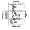
- FIG. 4 depicts simulated and measured input return loss and output isolation for the ring-hybrid diplexer as shown in FIG. 1A , FIG. 1B , and FIG. 2 .
- Return loss was measured at -27 dB and -20 dB for the frequencies of interest, at 1.9 GHz and 2.4 GHz respectively.
- -27 dB and -23 dB are the measured values of isolation provided at 1.9 GHz and 2.4 GHz respectively.
- the measured three-port return losses are not included here due to lack of space, they are matched at all ports as expected. It should be appreciated that the overall device can be further miniaturized in response to using substrates which exhibit high dielectric constants, and/or in response to creating denser circuit layouts.
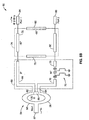
- FIG. 5A and FIG. 5B illustrate an example embodiment 50 of a quadrature-hybrid diplexer comprising a power divider, phase advance section, and dual-band quadrature hybrid.
- the two frequencies ( f 1 , f 2 ) are considered too widely separated for efficient use of the single-band hybrid approach described in the prior section.
- the first frequency f 1 and the second frequency f 2 being diplexed are at 1 GHz as shown in FIG. 5A , and 2 GHz as represented in FIG. 5B .
- a quadrature-hybrid-based diplexer 50 comprising an input 52, leading into a single-band power divider, exemplified as a Wilkinson power divider 54, having a first side 56, second side 58, and terminator 60 (e.g., a 100 ⁇ terminator is shown).
- Two outputs,62, 64 are shown from the power divider 54 to a phase advance section 66.
- the first output 62 leads to a first transmission line segment 68
- the second output 64 leads to a second transmission line segment 70.
- a CRLH phase-advance line 72 is interposed along the length of second transmission line segment 70.
- First and second transmission line segments are input to a dual-band CRLH 90° hybrid 74 having transmission line segments 76, 78, 80, and 82, depicted as comprising ⁇ /4 CRLH sections.
- a first port 84 and second port 86 are shown extending from quadrature hybrid 74.
- the two-way Wilkinson power divider 54 eases the junction design complexity and bisects signals evenly into the subsequent CRLH phase-advance section 66.
- the CRLH phase-advance section 66 is designed to exhibit a 90° phase-advance to excite the dual-band 90° coupler at both of the operating frequencies, which are 1 GHz, 2 GHz in the exemplified implementation to suite the phase responses of the dual-band CRLH 90° coupler. As shown in 5A at 1 GHz, the phase progression along each branch of the 90° coupler is 90° phase-advanced, whereby the constructive signal shows up at second port 86.
- signals at 2 GHz will be generated from the first port 84 when the -90° phase delay is assigned to each branch (76, 78, 80 and 82) of coupler 74 as shown FIG. 5B .
- the set of (90°, -90°) phase responses of the coupler are employed toward enhancing compactness. Therefore, the combination of (90°, 90°) CRLH phase-advance line with the (90°, -90°) quadrature hybrid is able to act as a diplexer at frequencies of interest.
- the CRLH quadrature hybrid is configured for operation at two selected frequencies which can have any desired relationship to one another.
- the implementation of the LH segments of the CRLH-TLs is also preferably in an SMT chip component form, or similar discrete lumped device format. Although, any desired relation can exist between the two frequencies utilized, there are considerations with regard to compactness. Considerations include electrical performance of the chip components at higher frequencies and the required length of microstrip lines, for a given implementation topology, which increases as the frequency separation is decreased given fixed phase responses.
- the dual-band CRLH hybrid is preferably composed of two pairs of CRLH transmission structures, such as having characteristic impedances 50 ⁇ (76, 82) and 50 2 ⁇ ⁇ (78, 80) respectively.
- the phase responses are 90° phase-advanced at 1 GHz and -90° phase-delayed at 2 GHz.
- this quadrature hybrid is compact and capable of arbitrary dual-band operation.
- the CRLH phase-advance line is designed to have phase responses (90°, 90°) at (1 GHz, 2 GHz) in this example. This requirement is realized by pairing a CRLH transmission structure with a microstrip line so that the CRLH transmission structure is phase advanced by 90° at both frequencies.
- the characteristic impedance of 50 ⁇ is used for both lines. Two unit-cell lumped elements are used.
- FIG. 6 depicts an actual implementation of the quadrature-hybrid-based diplexer configured for operation at 1 GHz and 2 GHz, which uses a single-band Wilkinson power divider, a CRLH phase-advance line, and a dual-band CRLH quadrature hybrid.
- FIG. 7 depicts simulated and measured insertion loss for the quadrature-hybrid diplexer shown in FIG. 5A , FIG. 5B , and FIG. 6 .
- the measured insertion loss is -1 dB and -0.9 dB at 1 GHz and 2 GHz respectively as shown in the graph. It will be noted that channel rejection, which filters out unwanted frequencies, is higher than 22 dB, while excellent agreement was achieved between the simulation and actual device measurements.
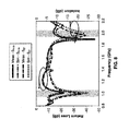
- FIG. 8 depicts simulated and measured input return loss and output isolation of the quadrature-hybrid -based diplexer shown in FIG. 5A , FIG. 5B , and FIG. 6 .
- Return loss was measured at -19 dB and -15 dB, for the frequencies of interest at 1 GHz and 2 GHz respectively.
- isolations values of -22 dB and -20 dB were obtained at 1 GHz and 2 GHz respectively.
- the test results illustrate the beneficial nature of the present invention, wherein diplexer embodiments can be readily implemented while providing return loss matching at each port.
- the input return loss of this diplexer can be improved by employing a dual-band Wilkinson power divider operating at 1 GHz and 2 GHz at the expense of design complexity. It should also be appreciated that the overall size of the device can be further miniaturized if substrates exhibiting high dielectric constants are utilized, and/or in response to the use of more dense circuit layouts.
- the present disclosure provides diplexing methods and apparatus utilizing a power divider, CRLH delay section, and CRLH hybrid coupler, which can be configured for two frequencies which need have no harmonic relationship with one another.
- Inventive teachings can be applied in a variety of apparatus and applications, including microwave signal demultiplexing, and so forth.
Landscapes
- Physics & Mathematics (AREA)
- Electromagnetism (AREA)
- Optics & Photonics (AREA)
- Waveguide Switches, Polarizers, And Phase Shifters (AREA)
- Cable Transmission Systems, Equalization Of Radio And Reduction Of Echo (AREA)
Claims (15)
- Diplexer-Vorrichtung (10, 50), die folgendes umfasst:einen Leistungsteiler (14, 54), der so konfiguriert ist, dass er ein Eingangssignal in ein erstes Signal und ein zweites Signal teilt;einen rechten und linken Phasenverzögerungs-Verbundleitungsabschnitt (26, 66), der ein erstes und ein zweites Übertragungsleitungssegment (28, 30; 68, 70) umfasst, wobei der Leitungsabschnitt mit Ausgängen (22, 24, 62, 64) des genannten Leistungsteilers gekoppelt ist und Elemente aufweist, die für eine Verzögerung oder Voreilung der Phase des genannten ersten Signals im Verhältnis zu dem genannten zweiten Signal konfiguriert sind; undeinen linken und rechten Verbund-Hybridkoppler (34, 74), der so konfiguriert ist, dass er das genannte erste Signal und das genannte zweite Signal von dem genannten Phasenverzögerungs-Verbundleitungsabschnitt empfängt und ein erstes Ausgangstor (36, 84) und ein zweites Ausgangstor (38, 86) aufweist;wobei:eine erste Betriebsfrequenz f 1, die mit den genannten Eingangssignalen empfangen wird, von dem genannten ersten Ausgangstor ausgegeben wird, und wobei eine zweite Betriebsfrequenz f 2, die mit den genannten Eingangssignalen empfangen wird, von dem genannten zweiten Ausgangstor ausgegeben wird; undwobei die genannte erste Betriebsfrequenz f 1 und die genannte zweite Betriebsfrequenz f 2 nicht gleich sind.
- Vorrichtung (10, 50) nach Anspruch 1, wobei der genannte Leistungsteiler (14, 54) als eine Verbindung mit drei Toren konfiguriert ist, welche das genannte erste Signal und das genannte zweite Signal ausgibt, die zueinander phasengleich sind mit gleichem Frequenzverlauf und im Wesentlichen der gleichen Leistung.
- Vorrichtung (10, 50) nach Anspruch 1, wobei der genannte linke und rechte Verbund-Hybridkoppler (34, 74) ein rechtes und linkes Übertragungsleitungsmaterial mit rechten und linken Abschnitten umfasst.
- Vorrichtung (10, 50) nach Anspruch 3, wobei der genannte linke und rechte Verbund-Hybridkoppler (34, 74) eine Mehrzahl von Einzelelementen umfasst, die induktive Widerstände und kapazitive Widerstände in den genannten linken Abschnitten der genannten rechten und linken Verbund-Übertragungsleitung umfassen.
- Vorrichtung (10, 50) nach einem der vorstehenden Ansprüche, wobei der genannte rechte und linke Phasenverzögerungs-Verbundleitungsabschnitt (26, 66) und der genannte rechte und linke Verbund-Hybridkoppler (34, 74) Übertragungsleitungen und Einzelelemente umfassen, die induktive Widerstände und kapazitive Widerstände umfassen, die bestimmt werden als Reaktion auf für die erste Betriebsfrequenz f 1 und die zweite Betriebsfrequenz f 2 ausgewählte Frequenzen.
- Vorrichtung (10) nach einem der vorstehenden Ansprüche, wobei:der genannte Hybridkoppler (34) einen Quadraturkoppler umfasst; undwobei der genannte hybride Quadraturkoppler Pfade für das genannte erste Signal und das genannte zweite Signal umfasst, die in der genannten ersten Betriebsfrequenz f 1 unterschiedlichen Phasenverzögerungen ausgesetzt sind als in der genannten zweiten Betriebsfrequenz f 2.
- Vorrichtung (10) nach Anspruch 1, wobei:der genannte Hybridkoppler (34) einen hybriden Ringkoppler umfasst; undwobei der genannte hybride Ringkoppler eine Mehrzahl von Toren (36, 38) umfasst, mit einem Summentor (36) und einem Differenztor (38), die entlang des genannten hybriden Ringkopplers angeordnet sind und entweder durch Phasenverzögerungen φ1 oder Phasenvoreilungen φ2 getrennt sind.
- Vorrichtung (50) nach Anspruch 1, wobei der genannte rechte und linke Hybridkoppler (74) ein rechtes und linkes Quadraturhybrid umfasst; und
wobei der genannte rechte und linke Phasenverzögerungs-Verbundleitungsabschnitt (26, 66) an das genannte erste Signal und das genannte zweite Signal die gleichen Phasenvoreilungen oder Phasenverzögerungen für die genannte erste Betriebsfrequenz f 1 und die genannte zweite Betriebsfrequenz f 2 bereitstellt. - Vorrichtung (10, 50) nach einem der vorstehenden Ansprüche, wobei:der genannte rechte und linke Phasenverzögerungs-Verbundleitungsabschnitt (26, 66) und der genannte rechte und linke Hybridkoppler (34, 74) ein rechtes und linkes Übertragungsleitungsmaterial sowohl mit rechten als auch mit linken Abschnitten umfassen; unddie rechten und linken Verbundabschnitte der genannten Vorrichtung für einen Betrieb in einem Mikrowellenfrequenzbereich konfiguriert sind, mit einer Übergangsfrequenz ω0 auf oder über etwa 100 MHz.
- Vorrichtung (10, 50) nach einem der vorstehenden Ansprüche, wobei:die Vorrichtung für einen wahlfreien Dualbandbetrieb auf den Frequenzen f 1 und f 2 konfiguriert ist; undwobei f 1 unabhängig ist von f 2 als Reaktion auf die Verwendung von Übertragungsleitungsabschnitten mit gestaltbarem nichtlinearem Phasenverlauf.
- Vorrichtung (10) nach Anspruch 1, wobei:der genannte Hybridkoppler (34) einen hybriden Ringkoppler umfasst;der genannte hybride Ringkoppler für einen Einzelbandbetrieb mit rechtem und linkem Verbund-Übertragungsleitungsmaterial mit rechten und linken Eigenschaften konfiguriert ist; undwobei der genannte Einzelbandbetrieb des genannten hybriden Ringkopplers einen Frequenzbereich umfasst, der sowohl Dualbandbetrieb die erste Betriebsfrequenz f 1 als auch die zweite Betriebsfrequenz f 2 aufweist.
- Vorrichtung (10) nach Anspruch 11, wobei:der genannte rechte und linke Phasenverzögerungs-Verbundleitungsabschnitt (26) so konfiguriert ist, dass er eine erste Phasenverzögerung auf der ersten Betriebsfrequenz f 1 bereitstellt und eine zweite Phasenverzögerung auf der zweiten Betriebsfrequenz f 2, und wobei die erste Phasenverzögerung und die zweite Phasenverzögerung nicht gleich sind.
- Vorrichtung (50) nach Anspruch 1, wobei:der genannte Hybridkoppler (74) einen hybriden Quadraturkoppler (74) umfasst;die genannte Vorrichtung (50) für einen wahlfreien Dualbandbetrieb auf einer ersten Betriebsfrequenz f 1 und einer zweiten Betriebsfrequenz f 2 konfiguriert ist, und wobei f 2 nicht gleich N x f 1 sein muss oder unabhängig ist von f 1 als Reaktion auf den Einsatz von Übertragungsleitungssegmenten mit gestaltbaren nichtlinearen Phasenverläufen; und wobeider genannte Phasenverzögerungs-Leitungsabschnitt (66) eine Phasenvoreilung von 90° vorsieht, um den hybriden Quadraturkoppler (74) sowohl auf der ersten Betriebsfrequenz f 1 zu erregen als auch auf der zweiten Betriebsfrequenz f 2.
- Vorrichtung (10, 50) nach Anspruch 1, wobei Dualfrequenzeigenschaften jedes Übertragungsleitungsabschnitts des genannten rechten und linken Verbund-Hybridkopplers (34, 74) entstehen als Reaktion auf ein antiparalleles Verhältnis zwischen Phasen- und Gruppengeschwindigkeiten unterhalb einer Übergangsfrequenz ω0 in den linken Abschnitten des genannten rechten und linken Verbund-Hybridkopplers und ein paralleles Verhältnis zwischen Phasen- und Gruppengeschwindigkeiten oberhalb der Übergangsfrequenz ω0 in den rechten Abschnitten des genannten rechten und linken Verbund-Hybridkopplers.
- Vorrichtung (10) nach Anspruch 1, wobei:der genannte Hybridkoppler (34) einen hybriden Ringkoppler umfasst; undder genannte Phasenverzögerungs-Leitungsabschnitt (26) so konfiguriert ist, dass er auf der ersten Betriebsfrequenz f 1 eine erste Verzögerung der Voreilung der Phase vorsieht und eine zweite Verzögerung oder Voreilung der Phase auf der zweiten Betriebsfrequenz f 2.
Applications Claiming Priority (2)
| Application Number | Priority Date | Filing Date | Title |
|---|---|---|---|
| US17996309P | 2009-05-20 | 2009-05-20 | |
| PCT/US2010/034903 WO2010135186A2 (en) | 2009-05-20 | 2010-05-14 | Diplexer synthesis using composite right/left-handed phase-advance/delay lines |
Publications (3)
| Publication Number | Publication Date |
|---|---|
| EP2433332A2 EP2433332A2 (de) | 2012-03-28 |
| EP2433332A4 EP2433332A4 (de) | 2013-01-09 |
| EP2433332B1 true EP2433332B1 (de) | 2014-07-09 |
Family
ID=43124201
Family Applications (1)
| Application Number | Title | Priority Date | Filing Date |
|---|---|---|---|
| EP10778170.0A Active EP2433332B1 (de) | 2009-05-20 | 2010-05-14 | Diplexersynthese mittels rechts- und linkshändigen phasen-vorschub-/verzögerungsleitungen |
Country Status (5)
| Country | Link |
|---|---|
| US (1) | US8405470B2 (de) |
| EP (1) | EP2433332B1 (de) |
| KR (1) | KR20120017452A (de) |
| CN (1) | CN102804485B (de) |
| WO (1) | WO2010135186A2 (de) |
Families Citing this family (17)
| Publication number | Priority date | Publication date | Assignee | Title |
|---|---|---|---|---|
| US8072291B2 (en) * | 2008-05-20 | 2011-12-06 | The Regents Of The University Of California | Compact dual-band metamaterial-based hybrid ring coupler |
| CN103414004B (zh) * | 2013-08-20 | 2015-10-28 | 电子科技大学 | 一种基于多层技术的0-dB定向耦合器 |
| US9935670B2 (en) | 2013-09-26 | 2018-04-03 | Qorvo Us, Inc. | Carrier aggregation using multiple antennas |
| US9985682B2 (en) * | 2013-10-24 | 2018-05-29 | Qorvo Us, Inc. | Broadband isolation low-loss ISM/MB-HB tunable diplexer |
| US9899986B2 (en) | 2013-10-24 | 2018-02-20 | Qoro US, Inc. | RF diplexer |
| CN103618125B (zh) * | 2013-11-20 | 2016-05-25 | 中国电子科技集团公司第四十一研究所 | 一种宽带大功率低损耗环形功率分配合成器 |
| JP6539119B2 (ja) * | 2014-06-13 | 2019-07-03 | 住友電気工業株式会社 | 電子装置 |
| US10615945B1 (en) * | 2015-12-05 | 2020-04-07 | L-3 Communications Corp. | Channel combiner supporting simultaneous multi-channel operation |
| CN105811059B (zh) * | 2016-03-30 | 2018-10-23 | 广东工业大学 | 一种高功率分配比三端口微带功分器 |
| CN106025472B (zh) * | 2016-06-28 | 2019-01-25 | 中国人民解放军空军工程大学 | 一种crlh分支线耦合器的结构及其设计方法 |
| CN106450623B (zh) * | 2016-12-05 | 2021-07-23 | 安徽四创电子股份有限公司 | 一种基于环形器的差分对线接口 |
| JP6526360B2 (ja) * | 2017-01-26 | 2019-06-05 | 三菱電機株式会社 | 高周波分波器及びこれを用いた高周波回路 |
| US12087867B2 (en) * | 2019-11-07 | 2024-09-10 | California Institute Of Technology | On-chip diplexed multi-band submillimeter-wave/terahertz sources |
| CN111628256B (zh) * | 2020-06-01 | 2021-10-22 | 中天宽带技术有限公司 | 一种高选择性双通带滤波器 |
| CN111834726B (zh) * | 2020-07-28 | 2022-04-19 | 南京理工大学 | 一种能实现高功分比的宽带滤波功分器 |
| CN113258243B (zh) * | 2021-04-28 | 2022-02-11 | 大连海事大学 | 一种具有平稳输出相位的宽带小型化混合环 |
| CN113964467B (zh) * | 2021-10-25 | 2022-05-17 | 金陵科技学院 | 一种基于三线耦合的平衡-非平衡式同相滤波功分器 |
Family Cites Families (6)
| Publication number | Priority date | Publication date | Assignee | Title |
|---|---|---|---|---|
| JPH06216687A (ja) * | 1993-01-18 | 1994-08-05 | Nippon Telegr & Teleph Corp <Ntt> | 周波数可変方向性結合器 |
| WO2002067367A1 (en) * | 2001-02-20 | 2002-08-29 | Axe, Inc. | High-frequency diplexer |
| US7508283B2 (en) | 2004-03-26 | 2009-03-24 | The Regents Of The University Of California | Composite right/left handed (CRLH) couplers |
| US7482893B2 (en) | 2006-05-18 | 2009-01-27 | The Regents Of The University Of California | Power combiners using meta-material composite right/left hand transmission line at infinite wavelength frequency |
| KR100883529B1 (ko) * | 2006-12-29 | 2009-02-12 | 주식회사 이엠따블유안테나 | 이중대역-crlh 전송 선로를 이용한 전력 분배기 및전력 합성기 |
| KR100930196B1 (ko) * | 2007-08-29 | 2009-12-07 | 한양대학교 산학협력단 | 안테나 급전 회로 및 이를 이용한 안테나 장치 |
-
2010
- 2010-05-14 EP EP10778170.0A patent/EP2433332B1/de active Active
- 2010-05-14 WO PCT/US2010/034903 patent/WO2010135186A2/en not_active Ceased
- 2010-05-14 KR KR1020117030398A patent/KR20120017452A/ko not_active Withdrawn
- 2010-05-14 CN CN201080031693.0A patent/CN102804485B/zh active Active
- 2010-05-14 US US12/780,190 patent/US8405470B2/en active Active
Also Published As
| Publication number | Publication date |
|---|---|
| US8405470B2 (en) | 2013-03-26 |
| CN102804485A (zh) | 2012-11-28 |
| EP2433332A2 (de) | 2012-03-28 |
| US20100295630A1 (en) | 2010-11-25 |
| WO2010135186A8 (en) | 2011-01-27 |
| WO2010135186A2 (en) | 2010-11-25 |
| EP2433332A4 (de) | 2013-01-09 |
| CN102804485B (zh) | 2014-10-08 |
| KR20120017452A (ko) | 2012-02-28 |
| WO2010135186A3 (en) | 2011-03-24 |
Similar Documents
| Publication | Publication Date | Title |
|---|---|---|
| EP2433332B1 (de) | Diplexersynthese mittels rechts- und linkshändigen phasen-vorschub-/verzögerungsleitungen | |
| CN101171747B (zh) | 滤波合成器 | |
| US8761026B1 (en) | Compact microstrip hybrid coupled input multiplexer | |
| Lin et al. | A Compact Filtering 180$^{\circ} $ Hybrid | |
| Zheng et al. | Differential RF phase shifter with harmonic suppression | |
| KR100883529B1 (ko) | 이중대역-crlh 전송 선로를 이용한 전력 분배기 및전력 합성기 | |
| EP2541674A1 (de) | Bandstopp-Filter mit hoher Unterdrückung und Diplexer mit derartigen Filtern | |
| JP2004096399A (ja) | 並列多段型帯域通過フィルタ | |
| Tu et al. | Design of microstrip low-pass–bandpass multiplexers using distributed coupling technique | |
| Tu et al. | Design of microwave microstrip multiband diplexers for system in package | |
| US7948332B2 (en) | N-channel multiplexer | |
| JP4842245B2 (ja) | トリプレクサ回路 | |
| Mezaal et al. | State of art on microstrip resonators, filters, diplexers and triplexers | |
| Velidi et al. | Design of compact microstrip diplexer with high selectivity | |
| Namdar et al. | A Survey on microstrip filters, diplexers, and triplexers state of art between 2018 and 2022 | |
| RU2533691C1 (ru) | Микрополосковый свч диплексор | |
| Lee et al. | Dual band isolation circuits based on CRLH transmission lines for triplexer application | |
| Zhu et al. | Wideband tunable reflection-type phase shifter using high-directivity directional coupler | |
| Chi et al. | Novel diplexer synthesis using the composite right/left-handed phase-advance/delay lines | |
| Cheng et al. | Directional coupler with good restraint outside the passband and its frequency-agile application | |
| Ge et al. | A Dual-Band Balun BPF Using Double-Sided Parallel-Strip Line | |
| Ogbodo | Novel microwave devices based on multi-port filtering networks | |
| Peik et al. | Switched superconductive filter-banks | |
| Kerketta et al. | Dual Channel Diplexer based on Stepped Impedance Filter and Microstrip Open-Loop Resonator | |
| Xu et al. | A Filtering Rat-Race Coupler Based on Coupling-Enhanced Structure |
Legal Events
| Date | Code | Title | Description |
|---|---|---|---|
| PUAI | Public reference made under article 153(3) epc to a published international application that has entered the european phase |
Free format text: ORIGINAL CODE: 0009012 |
|
| 17P | Request for examination filed |
Effective date: 20111219 |
|
| AK | Designated contracting states |
Kind code of ref document: A2 Designated state(s): AL AT BE BG CH CY CZ DE DK EE ES FI FR GB GR HR HU IE IS IT LI LT LU LV MC MK MT NL NO PL PT RO SE SI SK SM TR |
|
| RIN1 | Information on inventor provided before grant (corrected) |
Inventor name: CHI, PEI-LING Inventor name: ITOH, TATSUO |
|
| DAX | Request for extension of the european patent (deleted) | ||
| A4 | Supplementary search report drawn up and despatched |
Effective date: 20121210 |
|
| RIC1 | Information provided on ipc code assigned before grant |
Ipc: H01P 5/16 20060101ALI20121204BHEP Ipc: H01P 5/22 20060101ALI20121204BHEP Ipc: H01P 1/213 20060101AFI20121204BHEP |
|
| RIC1 | Information provided on ipc code assigned before grant |
Ipc: H01P 5/22 20060101ALI20130718BHEP Ipc: H01P 1/213 20060101AFI20130718BHEP Ipc: H01P 1/20 20060101ALI20130718BHEP Ipc: H01P 5/16 20060101ALI20130718BHEP |
|
| GRAP | Despatch of communication of intention to grant a patent |
Free format text: ORIGINAL CODE: EPIDOSNIGR1 |
|
| INTG | Intention to grant announced |
Effective date: 20130926 |
|
| GRAP | Despatch of communication of intention to grant a patent |
Free format text: ORIGINAL CODE: EPIDOSNIGR1 |
|
| INTG | Intention to grant announced |
Effective date: 20140225 |
|
| GRAS | Grant fee paid |
Free format text: ORIGINAL CODE: EPIDOSNIGR3 |
|
| GRAA | (expected) grant |
Free format text: ORIGINAL CODE: 0009210 |
|
| AK | Designated contracting states |
Kind code of ref document: B1 Designated state(s): AL AT BE BG CH CY CZ DE DK EE ES FI FR GB GR HR HU IE IS IT LI LT LU LV MC MK MT NL NO PL PT RO SE SI SK SM TR |
|
| REG | Reference to a national code |
Ref country code: GB Ref legal event code: FG4D |
|
| REG | Reference to a national code |
Ref country code: CH Ref legal event code: EP Ref country code: AT Ref legal event code: REF Ref document number: 676859 Country of ref document: AT Kind code of ref document: T Effective date: 20140715 |
|
| REG | Reference to a national code |
Ref country code: IE Ref legal event code: FG4D |
|
| REG | Reference to a national code |
Ref country code: DE Ref legal event code: R096 Ref document number: 602010017389 Country of ref document: DE Effective date: 20140814 |
|
| REG | Reference to a national code |
Ref country code: AT Ref legal event code: MK05 Ref document number: 676859 Country of ref document: AT Kind code of ref document: T Effective date: 20140709 |
|
| REG | Reference to a national code |
Ref country code: NL Ref legal event code: VDEP Effective date: 20140709 |
|
| REG | Reference to a national code |
Ref country code: LT Ref legal event code: MG4D |
|
| PG25 | Lapsed in a contracting state [announced via postgrant information from national office to epo] |
Ref country code: LT Free format text: LAPSE BECAUSE OF FAILURE TO SUBMIT A TRANSLATION OF THE DESCRIPTION OR TO PAY THE FEE WITHIN THE PRESCRIBED TIME-LIMIT Effective date: 20140709 Ref country code: FI Free format text: LAPSE BECAUSE OF FAILURE TO SUBMIT A TRANSLATION OF THE DESCRIPTION OR TO PAY THE FEE WITHIN THE PRESCRIBED TIME-LIMIT Effective date: 20140709 Ref country code: NO Free format text: LAPSE BECAUSE OF FAILURE TO SUBMIT A TRANSLATION OF THE DESCRIPTION OR TO PAY THE FEE WITHIN THE PRESCRIBED TIME-LIMIT Effective date: 20141009 Ref country code: SE Free format text: LAPSE BECAUSE OF FAILURE TO SUBMIT A TRANSLATION OF THE DESCRIPTION OR TO PAY THE FEE WITHIN THE PRESCRIBED TIME-LIMIT Effective date: 20140709 Ref country code: PT Free format text: LAPSE BECAUSE OF FAILURE TO SUBMIT A TRANSLATION OF THE DESCRIPTION OR TO PAY THE FEE WITHIN THE PRESCRIBED TIME-LIMIT Effective date: 20141110 Ref country code: GR Free format text: LAPSE BECAUSE OF FAILURE TO SUBMIT A TRANSLATION OF THE DESCRIPTION OR TO PAY THE FEE WITHIN THE PRESCRIBED TIME-LIMIT Effective date: 20141010 Ref country code: ES Free format text: LAPSE BECAUSE OF FAILURE TO SUBMIT A TRANSLATION OF THE DESCRIPTION OR TO PAY THE FEE WITHIN THE PRESCRIBED TIME-LIMIT Effective date: 20140709 Ref country code: BG Free format text: LAPSE BECAUSE OF FAILURE TO SUBMIT A TRANSLATION OF THE DESCRIPTION OR TO PAY THE FEE WITHIN THE PRESCRIBED TIME-LIMIT Effective date: 20141009 |
|
| PG25 | Lapsed in a contracting state [announced via postgrant information from national office to epo] |
Ref country code: IS Free format text: LAPSE BECAUSE OF FAILURE TO SUBMIT A TRANSLATION OF THE DESCRIPTION OR TO PAY THE FEE WITHIN THE PRESCRIBED TIME-LIMIT Effective date: 20141109 Ref country code: HR Free format text: LAPSE BECAUSE OF FAILURE TO SUBMIT A TRANSLATION OF THE DESCRIPTION OR TO PAY THE FEE WITHIN THE PRESCRIBED TIME-LIMIT Effective date: 20140709 Ref country code: CY Free format text: LAPSE BECAUSE OF FAILURE TO SUBMIT A TRANSLATION OF THE DESCRIPTION OR TO PAY THE FEE WITHIN THE PRESCRIBED TIME-LIMIT Effective date: 20140709 Ref country code: LV Free format text: LAPSE BECAUSE OF FAILURE TO SUBMIT A TRANSLATION OF THE DESCRIPTION OR TO PAY THE FEE WITHIN THE PRESCRIBED TIME-LIMIT Effective date: 20140709 Ref country code: PL Free format text: LAPSE BECAUSE OF FAILURE TO SUBMIT A TRANSLATION OF THE DESCRIPTION OR TO PAY THE FEE WITHIN THE PRESCRIBED TIME-LIMIT Effective date: 20140709 Ref country code: AT Free format text: LAPSE BECAUSE OF FAILURE TO SUBMIT A TRANSLATION OF THE DESCRIPTION OR TO PAY THE FEE WITHIN THE PRESCRIBED TIME-LIMIT Effective date: 20140709 Ref country code: NL Free format text: LAPSE BECAUSE OF FAILURE TO SUBMIT A TRANSLATION OF THE DESCRIPTION OR TO PAY THE FEE WITHIN THE PRESCRIBED TIME-LIMIT Effective date: 20140709 |
|
| REG | Reference to a national code |
Ref country code: DE Ref legal event code: R097 Ref document number: 602010017389 Country of ref document: DE |
|
| PG25 | Lapsed in a contracting state [announced via postgrant information from national office to epo] |
Ref country code: RO Free format text: LAPSE BECAUSE OF FAILURE TO SUBMIT A TRANSLATION OF THE DESCRIPTION OR TO PAY THE FEE WITHIN THE PRESCRIBED TIME-LIMIT Effective date: 20140709 Ref country code: CZ Free format text: LAPSE BECAUSE OF FAILURE TO SUBMIT A TRANSLATION OF THE DESCRIPTION OR TO PAY THE FEE WITHIN THE PRESCRIBED TIME-LIMIT Effective date: 20140709 Ref country code: IT Free format text: LAPSE BECAUSE OF FAILURE TO SUBMIT A TRANSLATION OF THE DESCRIPTION OR TO PAY THE FEE WITHIN THE PRESCRIBED TIME-LIMIT Effective date: 20140709 Ref country code: SK Free format text: LAPSE BECAUSE OF FAILURE TO SUBMIT A TRANSLATION OF THE DESCRIPTION OR TO PAY THE FEE WITHIN THE PRESCRIBED TIME-LIMIT Effective date: 20140709 Ref country code: EE Free format text: LAPSE BECAUSE OF FAILURE TO SUBMIT A TRANSLATION OF THE DESCRIPTION OR TO PAY THE FEE WITHIN THE PRESCRIBED TIME-LIMIT Effective date: 20140709 Ref country code: DK Free format text: LAPSE BECAUSE OF FAILURE TO SUBMIT A TRANSLATION OF THE DESCRIPTION OR TO PAY THE FEE WITHIN THE PRESCRIBED TIME-LIMIT Effective date: 20140709 |
|
| PLBE | No opposition filed within time limit |
Free format text: ORIGINAL CODE: 0009261 |
|
| STAA | Information on the status of an ep patent application or granted ep patent |
Free format text: STATUS: NO OPPOSITION FILED WITHIN TIME LIMIT |
|
| 26N | No opposition filed |
Effective date: 20150410 |
|
| PG25 | Lapsed in a contracting state [announced via postgrant information from national office to epo] |
Ref country code: SI Free format text: LAPSE BECAUSE OF FAILURE TO SUBMIT A TRANSLATION OF THE DESCRIPTION OR TO PAY THE FEE WITHIN THE PRESCRIBED TIME-LIMIT Effective date: 20140709 |
|
| REG | Reference to a national code |
Ref country code: CH Ref legal event code: PL |
|
| PG25 | Lapsed in a contracting state [announced via postgrant information from national office to epo] |
Ref country code: LU Free format text: LAPSE BECAUSE OF FAILURE TO SUBMIT A TRANSLATION OF THE DESCRIPTION OR TO PAY THE FEE WITHIN THE PRESCRIBED TIME-LIMIT Effective date: 20150514 Ref country code: CH Free format text: LAPSE BECAUSE OF NON-PAYMENT OF DUE FEES Effective date: 20150531 Ref country code: LI Free format text: LAPSE BECAUSE OF NON-PAYMENT OF DUE FEES Effective date: 20150531 Ref country code: MC Free format text: LAPSE BECAUSE OF FAILURE TO SUBMIT A TRANSLATION OF THE DESCRIPTION OR TO PAY THE FEE WITHIN THE PRESCRIBED TIME-LIMIT Effective date: 20140709 |
|
| REG | Reference to a national code |
Ref country code: IE Ref legal event code: MM4A |
|
| PG25 | Lapsed in a contracting state [announced via postgrant information from national office to epo] |
Ref country code: IE Free format text: LAPSE BECAUSE OF NON-PAYMENT OF DUE FEES Effective date: 20150514 |
|
| REG | Reference to a national code |
Ref country code: FR Ref legal event code: PLFP Year of fee payment: 7 |
|
| PG25 | Lapsed in a contracting state [announced via postgrant information from national office to epo] |
Ref country code: BE Free format text: LAPSE BECAUSE OF FAILURE TO SUBMIT A TRANSLATION OF THE DESCRIPTION OR TO PAY THE FEE WITHIN THE PRESCRIBED TIME-LIMIT Effective date: 20140709 |
|
| PG25 | Lapsed in a contracting state [announced via postgrant information from national office to epo] |
Ref country code: MT Free format text: LAPSE BECAUSE OF FAILURE TO SUBMIT A TRANSLATION OF THE DESCRIPTION OR TO PAY THE FEE WITHIN THE PRESCRIBED TIME-LIMIT Effective date: 20140709 |
|
| REG | Reference to a national code |
Ref country code: FR Ref legal event code: PLFP Year of fee payment: 8 |
|
| PG25 | Lapsed in a contracting state [announced via postgrant information from national office to epo] |
Ref country code: HU Free format text: LAPSE BECAUSE OF FAILURE TO SUBMIT A TRANSLATION OF THE DESCRIPTION OR TO PAY THE FEE WITHIN THE PRESCRIBED TIME-LIMIT; INVALID AB INITIO Effective date: 20100514 Ref country code: SM Free format text: LAPSE BECAUSE OF FAILURE TO SUBMIT A TRANSLATION OF THE DESCRIPTION OR TO PAY THE FEE WITHIN THE PRESCRIBED TIME-LIMIT Effective date: 20140709 |
|
| PG25 | Lapsed in a contracting state [announced via postgrant information from national office to epo] |
Ref country code: TR Free format text: LAPSE BECAUSE OF FAILURE TO SUBMIT A TRANSLATION OF THE DESCRIPTION OR TO PAY THE FEE WITHIN THE PRESCRIBED TIME-LIMIT Effective date: 20140709 |
|
| REG | Reference to a national code |
Ref country code: FR Ref legal event code: PLFP Year of fee payment: 9 |
|
| PG25 | Lapsed in a contracting state [announced via postgrant information from national office to epo] |
Ref country code: MK Free format text: LAPSE BECAUSE OF FAILURE TO SUBMIT A TRANSLATION OF THE DESCRIPTION OR TO PAY THE FEE WITHIN THE PRESCRIBED TIME-LIMIT Effective date: 20140709 |
|
| PG25 | Lapsed in a contracting state [announced via postgrant information from national office to epo] |
Ref country code: AL Free format text: LAPSE BECAUSE OF FAILURE TO SUBMIT A TRANSLATION OF THE DESCRIPTION OR TO PAY THE FEE WITHIN THE PRESCRIBED TIME-LIMIT Effective date: 20140709 |
|
| P01 | Opt-out of the competence of the unified patent court (upc) registered |
Effective date: 20230523 |
|
| PGFP | Annual fee paid to national office [announced via postgrant information from national office to epo] |
Ref country code: DE Payment date: 20250529 Year of fee payment: 16 |
|
| PGFP | Annual fee paid to national office [announced via postgrant information from national office to epo] |
Ref country code: GB Payment date: 20250527 Year of fee payment: 16 |
|
| PGFP | Annual fee paid to national office [announced via postgrant information from national office to epo] |
Ref country code: FR Payment date: 20250526 Year of fee payment: 16 |