EP2432011A1 - Dispositif de traitement et/ou de traitement de substrats - Google Patents
Dispositif de traitement et/ou de traitement de substrats Download PDFInfo
- Publication number
- EP2432011A1 EP2432011A1 EP11181301A EP11181301A EP2432011A1 EP 2432011 A1 EP2432011 A1 EP 2432011A1 EP 11181301 A EP11181301 A EP 11181301A EP 11181301 A EP11181301 A EP 11181301A EP 2432011 A1 EP2432011 A1 EP 2432011A1
- Authority
- EP
- European Patent Office
- Prior art keywords
- plane
- handling device
- substrate
- drives
- movement
- Prior art date
- Legal status (The legal status is an assumption and is not a legal conclusion. Google has not performed a legal analysis and makes no representation as to the accuracy of the status listed.)
- Withdrawn
Links
Images






Classifications
-
- H—ELECTRICITY
- H10—SEMICONDUCTOR DEVICES; ELECTRIC SOLID-STATE DEVICES NOT OTHERWISE PROVIDED FOR
- H10P—GENERIC PROCESSES OR APPARATUS FOR THE MANUFACTURE OR TREATMENT OF DEVICES COVERED BY CLASS H10
- H10P72/00—Handling or holding of wafers, substrates or devices during manufacture or treatment thereof
- H10P72/04—Apparatus for manufacture or treatment
- H10P72/0428—Apparatus for mechanical treatment or grinding or cutting
-
- H—ELECTRICITY
- H10—SEMICONDUCTOR DEVICES; ELECTRIC SOLID-STATE DEVICES NOT OTHERWISE PROVIDED FOR
- H10P—GENERIC PROCESSES OR APPARATUS FOR THE MANUFACTURE OR TREATMENT OF DEVICES COVERED BY CLASS H10
- H10P72/00—Handling or holding of wafers, substrates or devices during manufacture or treatment thereof
- H10P72/70—Handling or holding of wafers, substrates or devices during manufacture or treatment thereof for supporting or gripping
- H10P72/76—Handling or holding of wafers, substrates or devices during manufacture or treatment thereof for supporting or gripping using mechanical means, e.g. clamps or pinches
- H10P72/7604—Handling or holding of wafers, substrates or devices during manufacture or treatment thereof for supporting or gripping using mechanical means, e.g. clamps or pinches the wafers being placed on a susceptor, stage or support
- H10P72/7624—Handling or holding of wafers, substrates or devices during manufacture or treatment thereof for supporting or gripping using mechanical means, e.g. clamps or pinches the wafers being placed on a susceptor, stage or support characterised by the mechanical construction of the susceptor, stage or support
-
- H—ELECTRICITY
- H10—SEMICONDUCTOR DEVICES; ELECTRIC SOLID-STATE DEVICES NOT OTHERWISE PROVIDED FOR
- H10P—GENERIC PROCESSES OR APPARATUS FOR THE MANUFACTURE OR TREATMENT OF DEVICES COVERED BY CLASS H10
- H10P72/00—Handling or holding of wafers, substrates or devices during manufacture or treatment thereof
- H10P72/70—Handling or holding of wafers, substrates or devices during manufacture or treatment thereof for supporting or gripping
- H10P72/76—Handling or holding of wafers, substrates or devices during manufacture or treatment thereof for supporting or gripping using mechanical means, e.g. clamps or pinches
- H10P72/7604—Handling or holding of wafers, substrates or devices during manufacture or treatment thereof for supporting or gripping using mechanical means, e.g. clamps or pinches the wafers being placed on a susceptor, stage or support
- H10P72/7626—Handling or holding of wafers, substrates or devices during manufacture or treatment thereof for supporting or gripping using mechanical means, e.g. clamps or pinches the wafers being placed on a susceptor, stage or support characterised by the construction of the shaft
Definitions
- the invention relates to a device for the treatment and / or processing of substrates, in particular of flat substrates, in a closed space.
- the treatment for example, the surface treatment, and / or processing of flat substrates in enclosed spaces known.
- the advantage of a closed space is that conditions can be created in the room that differ from the ambient conditions. For example, pressure, temperature, chemical composition of the gas phase, etc., can be changed in a confined space.
- the enclosed space is a vacuum chamber in which, for example, coatings of glass substrates or wafers can be made at reduced pressure and high temperatures.
- the vacuum chamber has facilities that are to enable the transport of flat substrate from an inlet opening through the vacuum chamber to an outlet opening.
- treatment devices such as coating sources or etching devices are provided.
- the vacuum chamber may additionally contain heating devices, cooling devices, lighting, measuring technology and other components.
- the internal volume of the vacuum chamber would have to be kept as small as possible.
- the inclusion of the treatment devices, transport means, etc. in the vacuum chamber is necessarily associated with an increase in the internal volume of the chamber, which makes it difficult to establish the desired conditions in the chamber.
- the devices located in the chamber must also be adapted to the conditions provided in the vacuum chamber.
- the facilities must Among other things, be vacuum-resistant, chemically resistant and temperature resistant, which on the one hand makes the production of these facilities more expensive and on the other hand excludes the use of a variety of devices or components of these devices that could be used in ambient conditions. For this reason, for example, the use of many conventional drives is excluded.
- the object of the invention is to eliminate the disadvantages of the prior art.
- a device for the treatment and / or processing of substrates in a closed space should be specified, which allows the use of conventional drives.
- the device according to the invention further comprises a second handling device, which has a second plane and at least one drive for shifting the second plane in the direction of the surface normal of the second plane, wherein the second plane of the second handling device of the first plane of the first handling device is opposite.
- the second plane may be rigidly arranged in the direction of the surface normal of the second plane.
- the substrate can be inserted between the two planes, i. H. the first level and the second level are introduced.
- the first level is also referred to below as the main level.
- the second plane of the second handling device opposite the main plane is also referred to as the opposing plane. In the following, generally speaking of a plane, this refers to features that the first plane and / or the second plane can have.
- the movement of a plane in the direction of the surface normal of this plane can take place in a positive as well as in a negative direction.
- the movement is preferably a uniform movement.
- a movement in the direction of the surface normal of this plane is also referred to as transverse movement or stroke movement.
- a movement of the substrate in the plane or parallel to this is referred to as a transport movement.
- the movement of a plane in the direction of its surface normal can be used not only to change the position of a substrate, but also to treat and / or process the substrate, for example by using the force that can be used to move the main plane, to press the substrate against the opposite plane. In this way, for example, a change in shape of the substrate can be achieved.
- a change in shape of the substrate can be achieved.
- One of the advantages of the device according to the invention is the possibility to use conventional drives to effect a lifting movement of a plane within the enclosed space.
- the present invention thus enables both a reduction in the cost of manufacturing a device for treating and / or processing substrates in a confined space and a reduction in the cost of operating such a device.
- the drives used outside the enclosed space are not exposed to the climatic conditions in the enclosed space, so that conventional drives can be used, the materials and surfaces, for example, must not be vacuum, temperature and chemical resistant.
- the use of conventional components for the drives further reduces the cost of manufacturing the device of the invention.
- two or more drives are expediently provided for moving the respective plane of the handling device, wherein each of the drives is arranged outside the closed space.
- the drives of a plane are preferably connected to each other via control devices.
- the drives may be mechanically and / or electrically interconnected, for example. Multiple drives for the movement of a plane allow an exact movement of the plane and the maintenance of the plane within very close tolerances even under difficult conditions in the enclosed space.
- the plane is preferably divided into sub-areas of approximately the same size, each sub-area then being displaced by means of a separate drive. Due to the connection between the drives of a plane, the partial surfaces are largely simultaneously displaced by the same distance, so that an exact movement of the plane is achieved. In one embodiment of the invention, several drives for moving a partial surface can be provided.
- connection between the level of the handling device within the enclosed space and a drive of the handling device outside the enclosed space is preferably realized via a passage in the housing.
- an actuator such as a shaft, axle or rod such as a piston rod is guided, by means of which the drive generated by the drive is transmitted to the plane so that it performs the predetermined movement in the direction of their surface standards, whereby a shift of Level is reached.
- the passages are sealed by means of gaskets to prevent the conditions in the enclosed space from being adjusted to the ambient conditions.
- the movement generated by a drive can also be transmitted to the level of the handling device by means of a plurality of adjusting elements.
- two control elements per drive are provided, wherein the first control element is arranged outside the closed space and the second control element extends into the closed space.
- An area of the second control element forms a moving part of the housing.
- the first actuator can also be a shaft, axle or rod as a piston rod, the end of which acts on the said surface of the second actuator. In this case, the actuator is moved in the direction of the surface normal of the plane. The tightness of the housing is ensured by a diaphragm bellows.
- the diaphragm bellows is typically of tubular cross-section, with one end of this tubular structure being closed by said actuator surface, while the other end is secured to the rigid part of the housing relative to the actuators.
- the diaphragm bellows is thus opened only at one end face. In this opening, the adjusting element is inserted, so that one end of the first actuating element is in contact with said surface of the second actuating element.
- a diaphragm bellows allows complete separation of the sealed space from the environment.
- connection between the plane and each of its drives is expediently designed so that the materials can expand, which can be realized by a functional separation of guide and drive.
- the substrate is preferably a planar substrate, for example a disk-shaped structure such as a glass plate, a sheet, a foil or a composite of several layers, such as a wafer or a solar module.
- a planar substrate for example a disk-shaped structure such as a glass plate, a sheet, a foil or a composite of several layers, such as a wafer or a solar module.
- display disks, architectural glass, solar substrates, semiconductors etc. can be processed, for example coated.
- the planar substrate is expediently located on the plane.
- sheet substrate may also include a substrate that consists of a plurality of spatially separated units that rest on the plane. In particular, instead of a large-area substrate, a plurality of substrates, which are smaller in comparison, can rest on one level.
- treatment and / or processing of substrates is understood to mean in particular the processing, processing, refinement, shape change, temperature control, irradiation and testing of substrates and combinations thereof.
- plane is understood to mean a surface on which the substrate can rest over the entire surface.
- the plane can be the surface of an element. Since the plane according to the invention can be moved in the direction of its surface normal, this element is hereinafter referred to as a lifting element, the term "stroke" is only to describe the property of the element, just to be able to perform a movement of the plane of the element in the direction of the surface normal.
- the surface of the lifting element which forms the plane can have any desired contour. It may be, for example, a triangular, square, rectangular, circular or polygonal surface. Preferably, this surface is the surface of a plate, for example a metal plate.
- a plate for example a metal plate.
- Such a plate may be composed of sub-elements. For example, it can be made up of several segments and / or layers.
- a structure of the plate of several segments facilitates the manufacture of the lifting element, its installation and handling.
- a multi-layer plate construction facilitates the integration of actuators, sensors, tempering devices, and other devices into the plate.
- the surface of the plate, which forms the plane and on which the substrate can rest be provided with a coating which allows a gentle substrate contact.
- the lifting elements may further comprise stiffeners, for example ribs, which stabilize the surface which forms the plane and thus prevent deformations of the surface.
- the lifting element may be equipped with devices that are useful for the treatment and / or processing of the substrate.
- Such devices include, for example, cooling elements, heating elements, actuators, sensors, gas inlets (eg for technical gases), evaporators, devices for coating the substrate (eg sputtering sources), devices for testing the substrate, lighting elements, magnet systems, measuring instruments, Means for transporting the substrate and combinations thereof.
- a device for transporting the substrate can, for example, enable substrate transport in a vertical, horizontal or arbitrary angular position on the plane.
- ball rollers, support rollers, drive rollers, drive shafts, belts, step gear, lifting bars can be integrated into the lifting element.
- a belt conveyor whose upper strand is movable in the plane on which the substrate rests may be provided.
- wheels, rollers or shafts provided for transporting the substrate their axes of rotation should be parallel to the plane in the lifting element and whose radius correspond to the distance between its axis of rotation and the plane, so that the lateral surfaces of the wheels, rollers or shafts in contact with the Bottom of the substrate can get.
- the devices for the treatment / or processing of the substrate can be integrated in the handling devices, in particular in the lifting elements.
- the devices for the treatment and / or processing of the substrate may also be arranged spatially separate from the handling devices in the closed space.
- transport means may be provided, such as belt conveyors, which transport a substrate from the entrance opening of the enclosed space to the main plane and transfer the substrate there to the first handling device, to which the main plane to the level of Surface of the transport device on which the substrate rests, can be raised or lowered.
- a further transport device can be provided, which conveys the substrate from the main plane after the treatment and / or processing of the substrate to an exit opening.
- the handling devices may therefore comprise one or more guides.
- a guide is provided centrally of the plane (hereinafter referred to as a central guide) and at least one further guide spaced from the center of the plane and from the edge of the plane. These further guides are referred to below as peripheral guides.
- the central guide is preferably a fixed bearing.
- a uniform thermal expansion of the plane in all directions can be ensured.
- the amounts of expansion at the edges of the plane are equal, since the extent from the center to the edge of the plane is half the total extent of the plane.
- the fixed bearing prevents all movements of the plane, apart from the movement in the direction of their surface normal. If, in a Cartesian coordinate system, the surface normal is called the z-axis, the plane extends along the x and y coordinates. The fixed bearing thus prevents movements in the x, y direction, but movements in the z direction are permissible.
- the peripheral guides are preferably floating bearings.
- a rotation of the plane is prevented, while the extension of the plane in the longitudinal direction is possible, however.
- the floating bearings prevent the movement only in the x- or y-direction, so that movements of the plane in the z-direction and in the y-direction (when the movement in the x-direction is prevented by the floating bearing) or in the z-direction and in x Direction (when the movement in y-direction is prevented by the floating bearing) are possible.
- movable bearings are provided, they expediently permit a movement of the plane in the same directions, ie. H.
- All movable bearings allow the movement of the plane in the z-direction and in the x-direction or in the z-direction and in the y-direction.
- the floating bearings allow the movement of the plane in the z-direction and in the direction of the longest extent of the plane.
- guide elements are formed, for example, guide rods whose longitudinal axes are orthogonal to the plane. These guide rods are stretched between adjustable guide rollers whose axes of rotation are orthogonal to the longitudinal axes of the guide rods and whose lateral surfaces are in contact with the guide rods.
- the axes of rotation lie in one plane, wherein the axes of rotation of adjacent guide rollers extend at an angle of 120 ° or 90 ° to each other.
- the axes of rotation lie in a plane, the axes of rotation of both guide rollers parallel to each other.
- the guide rollers for the fixed bearing and the sub-bearings are preferably rotatably mounted on bearing blocks, wherein the bearing blocks can in turn be attached to the housing.
- a separate bearing block is provided for each role.
- openings may be formed in the housing through which the guide rods extend. These openings are closed by closures, for example in the form of hoods, which are the part of Guide rods, which protrude through the openings of the housing, enclose. This has the advantage that the volume of the enclosed space increases only slightly.
- the handling device which comprises the opposite plane also has such guides. This is also advantageous in a rigid counter-plane. Although the rigid opposing plane does not perform any movements in the direction of its surface normal, thermal expansion in the opposite plane in the x and / or y direction is possible.
- a closed room is understood here to mean a room that can be completely separated from the surroundings by means of a housing.
- openings may be provided, for example, to bring the substrate in the room can.
- passages are formed in the housing, through which the adjusting elements of the handling device are guided. Openings in the housing must be closable and / or sealed by means of seals so that contact between the space enclosed by the housing and the environment is prevented as much as possible.
- the enclosed space can be designated, for example, as a chamber, vacuum chamber, box, recipient, reactor, test environment, process space, etc.
- the space is terminated by the housing, the sealed and / or sealed openings in the housing such that special conditions can be established in the space. These include changes in the environment pressure conditions such as negative pressure or pressure, the introduction of technical gases and / or chemicals, the application of altered temperatures, magnetic fields, the prevention of the ingress of light or creating special lighting conditions and combinations of these conditions.
- the enclosed space may be connected to the atmosphere, peripheral equipment and / or components as well as to other enclosed spaces, namely preferably by means of valves, locks and / or flaps or directly without a sealing connection.
- the locked room does not have to be stationary. It may, for example, be subject to driving, swiveling and lifting movements.
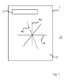
- FIGS. 2a to 2c The operation of the handling equipment is in the FIGS. 2a to 2c shown.
- two handling devices 6, 6 ' (see Fig. 2b ), although according to the invention the device may comprise only one handling device.
- a handling device 6 comprises a lifting element 7, which has a surface 8 which faces the flat substrate 4.
- the surface 8 is the main plane.
- the handling device 6 comprises Drives 9 and adjusting elements 10, which transmit the movement generated by the drives 9 to the lifting element 7.
- 1 bushings 11 are provided in the housing through which the adjusting elements 10 are guided.
- the passages 11 are sealed to prevent contact between the enclosed space 2 and the environment 3. Suitable bushings are, for example, membrane bellows.
- the drives 9 can cause a movement of the lifting element 7 in the direction of the surface normal of the main plane.
- the drives 9 of the handling device 6 are arranged outside the enclosed space in the environment 3, while the lifting elements 7 are arranged with the main plane 8 in the closed space 2.
- the drives can be for example motors, such as servo motors.
- the lifting element 7 may have treatment devices 5 which are integrated in the lifting element 7 and parts of the main plane 8. In the closed space, further treatment devices 5 "may be arranged which are not integrated into the lifting element 7.
- FIGS. 2a to 2c In addition to the first handling device 6, a second handling device 6 '(see Fig. 2b ) intended.
- the structure of this handling device 6 ' corresponds to the structure of the handling device 6.
- the reference numerals, the elements of the second handling device 6' show, which correspond to elements of the first handling device 6, therefore, a stroke has been added.
- the second handling device 6 ' comprises a lifting element 7', which has a surface 8 ', which forms the opposite plane.
- the opposite plane 8 ' is arranged opposite the main plane 8 and runs parallel to this. Between the main plane 8 and the opposite plane 8 'is the substrate. In other words, the main plane 8 faces one surface side of the substrate 4, while the opposite plane 8 'faces the other surface side of the substrate 4.
- the substrate 4 is held by the lifting element 7, the lifting element 7 'or both lifting elements 7, 7'.
- FIG. 2a the main plane 8, the opposing plane 8 'and the planar substrate 4 extend in the vertical direction, which is the position of the substrate 4 in FIG Fig. 1 equivalent.
- Fig. 2b the main plane 8, the opposing plane 8 'and the flat substrate 4 extend in the horizontal, which is the position of the substrate 4 marked in FIG. 4b Fig. 1 equivalent.
- Fig. 2c the main plane 8, the opposing plane 8 'and the flat substrate 4 extend in an angular position relative to the vertical and to the horizontal, which is the position of the substrate 4 in FIG Fig. 1 equivalent.
- Fig. 3 shows a section of an embodiment of the device according to the invention.
- the handling device 6 the lifting element 7 'of the handling device 6' with the opposite plane 8 'and a part of the housing 1, which separates the closed space 2 from the environment 3.
- the lifting element 7 of the handling device 6 is in the embodiment shown a plate-shaped structure having a surface which forms the main plane 8.
- reinforcements 13 are formed, which are to ensure the rigidity of the lifting element 7 and thus the main plane 8.
- the reinforcements comprise a plurality of webs 14 of the same length extending parallel to the surface normal and spaced apart, which extend from the underside of the lifting element 7 to a carrier 15 extending orthogonally to the webs 14.
- Each carrier 15 is connected via an adjusting element 10 with a drive 7.
- the actuator 10 is for example a shaft, axle or rod.
- the longitudinal axis of the actuating element 10 extends orthogonal to the plane 8.
- One end of such an actuating element 10 is fastened to the carrier 15, while the other end is in contact with the drive 9.
- each carrier is connected to a drive 7.
- Such carrier has an additional stiffening effect.
- Each handling device preferably comprises securing elements, in particular a retraction securing device.
- a retraction lock 16 is particularly useful when the marked by arrow A movement of the lifting element 7 coincides with the direction of gravitational force.
- the securing elements prevent movement of the main plane 8 without the action of the drives 9.
- the securing elements are preferably designed so that they do not hinder thermal expansion of the main plane 8 in the x and / or y-direction.
- a retraction fuse 16 At the in Fig. 3 shown embodiment of the device according to the invention is provided at the end of the adjusting element 10 which is fixed to the carrier 15, a retraction fuse 16. It can be a bracket or a backdrop.
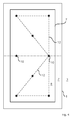
- Fig. 4 shows the arrangement of the adjusting elements 10 of a handling device 6 with respect to the main plane 8. Shown is the plan view of the plane 8 of the lifting element 7.
- the adjusting elements 10, each at their ends in contact with the underside of a lifting element 7 or a carrier 15th are and their Longitudinal axis orthogonal to the plane 8, transmit the movement of the drives 9 to the lifting element 7, whereby the plane 8 is moved in the direction of its surface normal.
- the adjusting elements 10 are uniformly distributed in relation to the main plane 8, so that the force generated by drives 7 can act evenly on the lifting element 7, which causes an exact and uniform movement of the plane 8.
- the position of the adjusting elements 10 in the plane 8 are marked by stars.
- the dashed line shows the control devices 12, which cause a synchronization of the drives 9 and thus the movement of the adjusting elements 10.
- Such an arrangement of the adjusting elements can also be provided for the handling device 6 'with the opposing plane 8'.
- Fig. 5 Contours of the plane 8 are shown, wherein the opposing plane 8 'may also have such contours.
- the plane may have a round, octagonal or polygonal contour.
- the planes 8, 8 ' can each be composed of sub-areas 26 (see FIGS. 5a and 5b ).
- the lifting element 7, 7 'be composed of interconnected segments, which increases the stability and simplifies manufacture and handling of the lifting elements.
- Fig. 6 shows a section of a handling device 6 according to the invention in a schematic representation, wherein the handling device of in Fig. 4 shown, wherein it is additionally shown that the lifting element 7 is a plate-shaped hollow body, wherein in the cavity a treatment device 5a, for example, a tempering device such as cooling or heating, is introduced. Furthermore, the handling device additionally comprises treatment devices 5b, which can effect a transport movement of the substrate 4 on the main plane 8.
- The are disc-shaped, wherein on the lateral surfaces of the discs pads made of plastic, which can come into contact with the underside of the substrate 4. In the main plane 8 openings are formed through which the treatment devices 5b are guided so that they can come into contact with the substrate 4.
- the lifting element 7 'of the second handling device 6' is additionally shown, which forms the opposite plane 8.
- the lifting element 7 ' may be a plate-shaped hollow body, in the cavity of which a treatment device 5 a', for example a tempering device such as cooling or heating, is introduced.
- the arrows A and A ' illustrate a movement of the two planes 8, 8' along their surface normal in the opposite direction.
- the forces of the drives 9, 9 'in the direction of arrow A, A' act on the substrate.
- the two planes 8, 8 ' can be moved independently of one another in the opposite direction to the direction of the arrows A, A'.
- both planes 8, 8 ' can be moved independently of one another in the direction of arrow A, A' or opposite thereto, as long as the movement takes place along the surface normals of the respective planes 8, 8 ', as in FIGS FIGS. 2a to 2c is shown.
- the first actuator 10a is located outside the closed space 2, while the second actuator 10b extends into the closed space 2 and forms a movable part of the housing 1.
- the first adjusting element 10a is, for example, a piston rod whose end acts on the second adjusting element 10b.
- the second control element 10b is moved in the direction of the surface normal of the main plane 8.
- the tightness of the housing 1 is ensured by a diaphragm bellows 17.
- the diaphragm bellows has a substantially tubular cross-section, one end face of this tube-like structure being closed by the second actuating element 10b, while the other end face is fastened to the part of the housing 1 which is rigid in relation to the actuating elements via a flange 19.
- the diaphragm bellows 17 is thus opened only at one end face.
- the first adjusting element 10a is inserted, so that one end of the first adjusting element 10a is in contact with the underside of the second adjusting element 10b.
- a Web 18 is formed, which adjoins the underside of the lifting element 7.
- a membrane bellows typically consists of several membrane pairs.
- the membrane bellows are preferably made of stainless steel. The terms "above” and below "refer only to those in Fig. 8 shown illustration and should only identify the position of the components to each other.
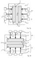
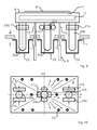
- FIGS. 9 to 12 show an embodiment of a handling device 6, which has guides for the lifting element 7.
- These guides comprise guide rods 20a, 20b which extend from the underside of the lifting element 7 in the orthogonal direction with respect to the plane 8.
- the guide rods 20a, 20b are stretched between guide rollers 21a, 21b whose axes of rotation are orthogonal to the longitudinal axis of the guide rods 20a, 20b and whose lateral surfaces are in contact with the guide rods 20a, 20b.
- hoods 22 are provided which receive part of the guide rods 20a, 20b. The contact points between the hoods 22 and the housing 1 are closed by seals 23.
- the centrally disposed to the plane guide rod 20a together with the bearings 21a is a fixed bearing, which is the central guide.
- the fixed bearing has four guide rollers whose axes of rotation lie in one plane, wherein the axes of rotation of adjacent guide rollers extend at an angle of 90 ° to each other.
- the other two guides with the guide rods 20b and the guide rollers 21b are movable bearings.
- Both movable bearings each have two guide rollers 21b whose axes of rotation lie in one plane, the axes of rotation of both guide rollers 21b extending parallel to one another.
- the movable bearings allow the expansion of the plane 8 in the x direction.
- the guide rollers for the fixed bearing and the sub-bearings are, as for the central guide in the Figures 12a and 12b is rotatably mounted on bearing blocks 23, wherein the bearing blocks are in turn secured to the housing 1.
- Fig. 13 shows an embodiment of a lifting element 7, in which a treatment device 5 is provided in the form of support rollers 25.
- the support rollers 25 allow the transport of the substrate 4 parallel to the plane 8, wherein the axes of rotation of the support rollers 25 are parallel to the surface normal of the plane 8 and the lateral surfaces of the support rollers 25 can come into contact with the substrate.
Landscapes
- Container, Conveyance, Adherence, Positioning, Of Wafer (AREA)
Applications Claiming Priority (1)
| Application Number | Priority Date | Filing Date | Title |
|---|---|---|---|
| DE102010045411A DE102010045411A1 (de) | 2010-09-15 | 2010-09-15 | Vorrichtung zur Behandlung und/oder Bearbeitung von Substraten |
Publications (1)
| Publication Number | Publication Date |
|---|---|
| EP2432011A1 true EP2432011A1 (fr) | 2012-03-21 |
Family
ID=44799634
Family Applications (1)
| Application Number | Title | Priority Date | Filing Date |
|---|---|---|---|
| EP11181301A Withdrawn EP2432011A1 (fr) | 2010-09-15 | 2011-09-14 | Dispositif de traitement et/ou de traitement de substrats |
Country Status (2)
| Country | Link |
|---|---|
| EP (1) | EP2432011A1 (fr) |
| DE (1) | DE102010045411A1 (fr) |
Cited By (1)
| Publication number | Priority date | Publication date | Assignee | Title |
|---|---|---|---|---|
| EP2990201A1 (fr) | 2014-08-29 | 2016-03-02 | Uwe Beier | Dispositif et procede de fabrication d'un substrat composite, qui comprend au moins un premier substrat en forme de bande et un second substrat en forme de bande |
Citations (3)
| Publication number | Priority date | Publication date | Assignee | Title |
|---|---|---|---|---|
| US20050020177A1 (en) * | 2002-02-22 | 2005-01-27 | Lg. Philips Lcd Co., Ltd. | Apparatus and method for manufacturing liquid crystal display devices |
| US20080138936A1 (en) * | 2006-12-06 | 2008-06-12 | Nitto Denko Corporation | Method for laminating substrate and apparatus using the method |
| WO2009063906A1 (fr) * | 2007-11-16 | 2009-05-22 | Ulvac, Inc. | Appareil et procédé de fabrication de substrat de liaison |
Family Cites Families (3)
| Publication number | Priority date | Publication date | Assignee | Title |
|---|---|---|---|---|
| US6380751B2 (en) * | 1992-06-11 | 2002-04-30 | Cascade Microtech, Inc. | Wafer probe station having environment control enclosure |
| DE10048881A1 (de) * | 2000-09-29 | 2002-03-07 | Infineon Technologies Ag | Vorrichtung und Verfahren zum planen Verbinden zweier Wafer für ein Dünnschleifen und ein Trennen eines Produkt-Wafers |
| DE212007000083U1 (de) * | 2006-10-31 | 2009-07-16 | "Nauchnoe I Tekhnologicheskoe Oborudovanie" Limited | Züchtungsmanipulator |
-
2010
- 2010-09-15 DE DE102010045411A patent/DE102010045411A1/de not_active Withdrawn
-
2011
- 2011-09-14 EP EP11181301A patent/EP2432011A1/fr not_active Withdrawn
Patent Citations (3)
| Publication number | Priority date | Publication date | Assignee | Title |
|---|---|---|---|---|
| US20050020177A1 (en) * | 2002-02-22 | 2005-01-27 | Lg. Philips Lcd Co., Ltd. | Apparatus and method for manufacturing liquid crystal display devices |
| US20080138936A1 (en) * | 2006-12-06 | 2008-06-12 | Nitto Denko Corporation | Method for laminating substrate and apparatus using the method |
| WO2009063906A1 (fr) * | 2007-11-16 | 2009-05-22 | Ulvac, Inc. | Appareil et procédé de fabrication de substrat de liaison |
Cited By (2)
| Publication number | Priority date | Publication date | Assignee | Title |
|---|---|---|---|---|
| EP2990201A1 (fr) | 2014-08-29 | 2016-03-02 | Uwe Beier | Dispositif et procede de fabrication d'un substrat composite, qui comprend au moins un premier substrat en forme de bande et un second substrat en forme de bande |
| DE102014112490A1 (de) | 2014-08-29 | 2016-03-03 | Uwe Beier | Vorrichtung und Verfahren zum Herstellen eines Substratverbundes, der zumindest ein erstes bandförmiges Substrat und ein zweites bandförmiges Substrat umfasst |
Also Published As
| Publication number | Publication date |
|---|---|
| DE102010045411A1 (de) | 2012-03-15 |
Similar Documents
| Publication | Publication Date | Title |
|---|---|---|
| EP2315236B1 (fr) | Soupape de transfert à clapets | |
| DE4210110C2 (de) | Halbleitereinrichtung-Herstellungsvorrichtung und Verfahren zum Herstellen einer Halbleitereinrichtung | |
| DE69713065T2 (de) | Ladungsschleusenvorrichtung für ein ionenimplantierungssystem | |
| DE69023633T2 (de) | Kathodenzerstäubungsgerät und kathodenzerstäubungsanlage. | |
| DE102009004493B3 (de) | Vakuumbeschichtungsanlage und Verfahren zum Betrieb einer Vakuumbeschichtungsanlage | |
| EP2422362B1 (fr) | Dispositif de transport à cadre d'étanchéité pouvant subir un fléchissement | |
| DE112013005732B4 (de) | Sputtergerät und Substratbearbeitungsgerät | |
| WO2010115917A1 (fr) | Soupape à dépression et système de chambre à vide | |
| DE102011050324A1 (de) | Substrattransportmodul, Belade- und Entladesystem und Transportverfahren für Substrate in einer Substratbearbeitungsanlage | |
| DE102011101088A1 (de) | Vorrichtung zum Ausrichten eines Substrates und einer Maske | |
| EP2432011A1 (fr) | Dispositif de traitement et/ou de traitement de substrats | |
| DE102010028958B4 (de) | Substratbehandlungsanlage | |
| EP3368705A1 (fr) | Dispositif et procédé de revêtement de substrats de type plats allongés, notamment plaques de verre, dans une installation de revêtement sous vide | |
| CH681015A5 (fr) | ||
| EP2944451B1 (fr) | Machine de formage thermique | |
| DE102011050844A1 (de) | Vorrichtung zur Behandlung und/oder Bearbeitung von Substraten | |
| DE102014106467A1 (de) | Ventilanordnung, Vakuumkammeranordnung und Verfahren zum Abdichten einer Substrat-Transfer-Öffnung. | |
| DE3008325C2 (fr) | ||
| DE10227856A1 (de) | Verfahren und Vorrichtung zum Herstellen eines LCD | |
| DE102012110287B4 (de) | Substratbehandlungsanlage und Verfahren zur Druckminderung | |
| DE102012110052B3 (de) | Batch-Anlage und Verfahren zur Behandlung von Substraten | |
| DE102020204100A1 (de) | Neues Montageverfahren zum Installieren von Bogenmaterial | |
| DE102012000397A1 (de) | Befestigungsmittel in einer Anlage zur Vakuumbehandlung | |
| DE102015113658B3 (de) | Vakuum-Drehdurchführung und Vakuum-Substratbehandlungsanlage | |
| DE102019124484A1 (de) | Ventilanordnung, Vakuumanordnung und Verfahren |
Legal Events
| Date | Code | Title | Description |
|---|---|---|---|
| PUAI | Public reference made under article 153(3) epc to a published international application that has entered the european phase |
Free format text: ORIGINAL CODE: 0009012 |
|
| AK | Designated contracting states |
Kind code of ref document: A1 Designated state(s): AL AT BE BG CH CY CZ DE DK EE ES FI FR GB GR HR HU IE IS IT LI LT LU LV MC MK MT NL NO PL PT RO RS SE SI SK SM TR |
|
| AX | Request for extension of the european patent |
Extension state: BA ME |
|
| 17P | Request for examination filed |
Effective date: 20120329 |
|
| 17Q | First examination report despatched |
Effective date: 20180925 |
|
| STAA | Information on the status of an ep patent application or granted ep patent |
Free format text: STATUS: THE APPLICATION IS DEEMED TO BE WITHDRAWN |
|
| 18D | Application deemed to be withdrawn |
Effective date: 20200103 |