EP2431815A2 - Driving device and image forming apparatus - Google Patents
Driving device and image forming apparatus Download PDFInfo
- Publication number
- EP2431815A2 EP2431815A2 EP11181432A EP11181432A EP2431815A2 EP 2431815 A2 EP2431815 A2 EP 2431815A2 EP 11181432 A EP11181432 A EP 11181432A EP 11181432 A EP11181432 A EP 11181432A EP 2431815 A2 EP2431815 A2 EP 2431815A2
- Authority
- EP
- European Patent Office
- Prior art keywords
- roller
- tension roller
- transfer belt
- rotation
- intermediate transfer
- Prior art date
- Legal status (The legal status is an assumption and is not a legal conclusion. Google has not performed a legal analysis and makes no representation as to the accuracy of the status listed.)
- Withdrawn
Links
Images


Classifications
-
- G—PHYSICS
- G03—PHOTOGRAPHY; CINEMATOGRAPHY; ANALOGOUS TECHNIQUES USING WAVES OTHER THAN OPTICAL WAVES; ELECTROGRAPHY; HOLOGRAPHY
- G03G—ELECTROGRAPHY; ELECTROPHOTOGRAPHY; MAGNETOGRAPHY
- G03G15/00—Apparatus for electrographic processes using a charge pattern
- G03G15/14—Apparatus for electrographic processes using a charge pattern for transferring a pattern to a second base
- G03G15/16—Apparatus for electrographic processes using a charge pattern for transferring a pattern to a second base of a toner pattern, e.g. a powder pattern, e.g. magnetic transfer
- G03G15/1605—Apparatus for electrographic processes using a charge pattern for transferring a pattern to a second base of a toner pattern, e.g. a powder pattern, e.g. magnetic transfer using at least one intermediate support
- G03G15/1615—Apparatus for electrographic processes using a charge pattern for transferring a pattern to a second base of a toner pattern, e.g. a powder pattern, e.g. magnetic transfer using at least one intermediate support relating to the driving mechanism for the intermediate support, e.g. gears, couplings, belt tensioning
-
- G—PHYSICS
- G03—PHOTOGRAPHY; CINEMATOGRAPHY; ANALOGOUS TECHNIQUES USING WAVES OTHER THAN OPTICAL WAVES; ELECTROGRAPHY; HOLOGRAPHY
- G03G—ELECTROGRAPHY; ELECTROPHOTOGRAPHY; MAGNETOGRAPHY
- G03G15/00—Apparatus for electrographic processes using a charge pattern
- G03G15/01—Apparatus for electrographic processes using a charge pattern for producing multicoloured copies
- G03G15/0105—Details of unit
- G03G15/0131—Details of unit for transferring a pattern to a second base
-
- G—PHYSICS
- G03—PHOTOGRAPHY; CINEMATOGRAPHY; ANALOGOUS TECHNIQUES USING WAVES OTHER THAN OPTICAL WAVES; ELECTROGRAPHY; HOLOGRAPHY
- G03G—ELECTROGRAPHY; ELECTROPHOTOGRAPHY; MAGNETOGRAPHY
- G03G15/00—Apparatus for electrographic processes using a charge pattern
- G03G15/01—Apparatus for electrographic processes using a charge pattern for producing multicoloured copies
- G03G15/0142—Structure of complete machines
- G03G15/0178—Structure of complete machines using more than one reusable electrographic recording member, e.g. one for every monocolour image
- G03G15/0189—Structure of complete machines using more than one reusable electrographic recording member, e.g. one for every monocolour image primary transfer to an intermediate transfer belt
Definitions
- the present invention relates to a driving device in which a stretched member (for example, as an endless belt) is stretched around a plurality of rollers and moved by the rollers, and an image forming apparatus using the driving device.
- a stretched member for example, as an endless belt
- the present invention is intended to solve the above described problems, and an object of the present invention to provide a driving device and an image forming apparatus capable of lengthen a lifetime of a stretched member.
- a driving device including a stretched member, and a first rotation member and a second rotation member around which the stretched member is stretched.
- the first rotation member has a first rotation axis
- the second rotation member has a second rotation axis.
- the first rotation member includes a plurality of members arranged in an axial direction of said first rotation axis.
- an image forming unit including the above described driving device.
- FIG. 1 is a schematic view showing a configuration of an image forming apparatus 10 according to the first embodiment of the present invention.
- the image forming apparatus 10 is configured as, for example, an electrophotographic printer of an intermediate transfer type.
- the image forming apparatus 10 includes a medium tray 11 in which recording media (for example, sheets) P are stored.
- a medium feeding unit 12 is provided on a feeding side (i.e., left side in FIG. 1 ) of the medium tray 11.
- the medium feeding unit 12 is configured to feed the recording medium P one by one out of the medium tray 11.
- the medium feeding unit 12 includes a pickup roller 12a pressed against the topmost recording medium P lifted to a predetermined height.
- the medium feeding unit 12 further includes a feeding roller 12b and a retard roller 12c for separately feeding the recording medium P picked up by the pickup roller 12a.
- a medium conveying unit 13 is provided on a downstream side of the medium feeding unit 12 in a conveying direction of the recording medium P.
- the medium conveying unit 13 includes a plurality of conveying roller pairs 13a, 13b and 13c for conveying the recording medium P toward a transfer roller 15 described later.
- An image forming portion 20 includes four toner image forming units 30 (30C, 30M, 30Y and 30K) as developer image forming units, four transfer rollers 14 (14C, 14M, 14Y and 14K), and a transfer roller 15.
- the toner image forming units 30 are arranged in tandem, and respectively form toner images (i.e., developer images).
- the transfer rollers 14 are configured to primarily transfer the toner images to an intermediate transfer belt 41 described later.
- the transfer roller 15 is configured to secondarily transfer the toner image from the intermediate transfer belt 41 to the recording medium P. Therefore, the transfer rollers 14 are also referred to as primary transfer rollers, and the transfer roller 15 are also referred to as a secondary transfer roller.
- the toner image forming units 30 include OPC (Organic Photo Conductor) drums 31 (31C, 31M, 31Y, 31K) as image bearing bodies that bear toner images, charging rollers 32 (32C, 32M, 32Y, 32K) as charging members that negatively charge the surfaces of the OPC drums 31, printing heads 33 (33C, 33M, 33Y, 33K) as exposure units that expose the surfaces of the OPC drums 31 to form latent images, developing rollers 34 (34C, 34M, 34Y, 34K) as developing members that develop the latent images to form toner images, and developer supply units 35 (35C, 35M, 35Y and 35K) that supply toners to the developing rollers 34.
- the printing heads 33 are constituted by, for example, LED (Light Emitting Diode) arrays.
- a transfer belt unit 40 as a driving device includes an intermediate transfer belt 41 (i.e., a stretched member).
- the intermediate transfer belt 41 also functions as a toner (developer) image bearing body.
- the intermediate transfer belt 41 is an endless belt, and is configured to carry the toner image having been primarily transferred by the transfer rollers 14.
- the transfer belt unit 40 further includes a driving roller 42 as a second rotation member, a tension roller 43 as a first rotation member, and a backup roller 44.
- the driving roller 42 is driven by a driving motor 110, and drives the intermediate transfer belt 41 in a belt conveying direction shown by an arrow X corresponding to counterclockwise direction in FIG. 1 .
- the tension roller 43 is provided so as to face the driving roller 42.
- the intermediate transfer belt 41 is stretched (wound) around the driving roller 42, the tension roller 43 and the transfer roller 15.
- the backup roller 44 is provided so as to face the transfer roller 15 via the intermediate transfer belt 41.
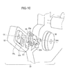
- the transfer belt unit 40 (as the driving unit) includes a correction portion 50 ( FIG. 10 ) at an end of the tension roller 43.
- the correction portion 50 includes an arm 52, springs 53L and 53R, bearings 54L and 54R, a lever 55 and a pulley 56. Detailed description of these parts will be made later.
- a fixing portion 16 is provided on the downstream side of the transfer roller 15 (as the secondary transfer roller).
- the fixing portion 16 is configured to fix the toner image (i.e., the developer image) to the recording medium P by applying heat and pressure.
- the fixing portion 16 includes an upper roller 16a and a lower roller 16b both of which have surface layers made of resilient bodies.
- the upper roller 16a and the lower roller 16b have halogen lamps 16c and 16d (as internal heat sources) therein.
- Ejection roller pairs 17a, 17b and 17c are provided on the downstream side of the fixing portion 16.
- the ejection roller pairs 17a, 17b and 17c eject the recording medium P to the outside of the image forming apparatus 10.
- a stacker portion 18 is provided on an upper part of the image forming apparatus 10 on which the ejected recording medium P is placed.
- the image forming apparatus 10 has a power source 120.
- the power source 120 supplies electric power for entire operation of the image forming apparatus 10.
- the power source 120 applies voltages to the charging rollers 32 (32C, 32M, 32Y, 32K), the developing rollers 34 (34C, 34M, 34Y, 34K), the primary transfer rollers 14 (14C, 14M, 14Y, 14K) and the secondary transfer roller 15.
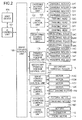
- FIG. 2 is a block diagram showing a control system of the image forming apparatus 10 of the first embodiment.
- An image forming control unit 100 as a control unit includes a microprocessor, ROM, RAM, input-output port, timer and the like.
- the image forming control unit 100 receives image data (print data) and control command from a host device 10A, and performs sequence control of the entire image forming apparatus 10 to thereby perform a printing operation.
- An I/F control unit 101 sends printer information to the host device 10A, analyzes command sent from the host device 10A, and processes data sent from the host device 10A.
- a charge voltage control unit 102 controls application of voltages to the charging rollers 32 to thereby charge the surfaces of OPC drums 31 according to a command from the image forming control unit 100.
- a head control unit 103 controls the printing heads 33 to emit lights to expose the surfaces of the OPC drums 31 according to a command from the image forming control unit 100 so as to form latent images the OPC drums 31.
- a developing voltage control unit 104 controls application of voltages to the developing rollers 34 according to a command from the image forming control unit 100 so as to cause the toner (i.e., developer) to adhere to the latent images formed on the surfaces of the OPC drums 31 by the printing heads 33.
- toner i.e., developer
- a primary transfer voltage control unit 105 controls application of voltages to the (primary) transfer rollers 14 according to a command from the image forming control unit 100 so as to transfer the toner images on the surfaces of the OPC drums 31 to the intermediate transfer belt 41 (as the endless belt or the developer image bearing body).
- a secondary transfer voltage control unit 106 controls application of a voltage to the secondary transfer roller 15 according to a command from the image forming control unit 100 so as to transfer the toner image from the intermediate transfer belt 41 to the recording medium P.
- An image forming driving control unit 107 controls drive motors 112C, 112M, 112Y, 112K for rotating the OPC drums 31, the charging rollers 32, the developing rollers 34 according to a command from the image forming control unit 100.
- a belt driving control unit 108 controls the driving motor 110 according to a command from the image forming control unit 100 so as to rotate the driving roller 42 to move the intermediate transfer belt 41.
- the rotation of the driving roller 42 is transmitted to the tension roller 43 and the backup roller 44 via the intermediate transfer belt 41, and the tension roller 43 and the backup roller 44 also rotate.
- the transfer roller 15 contacting the intermediate transfer belt 41 also rotates.
- a feeding-conveying control unit 109 controls a feeding motor 115 and a conveying motor 116 according to a command from the image forming control unit 100 so as to feed and convey the recording medium P.
- the feeding motor 115 drives the pickup roller 12a, the feeding roller 12b, and the conveying roller pairs 13a and 13b.
- the conveying motor 116 drives the conveying roller pair 13c.
- a fixing control unit 111 controls application of voltages to heaters 16c and 16d of the fixing portion 16 according to a command from the image forming control unit 100 so as to fix the toner image to the recording medium P. More specifically, the fixing control unit 111 receives temperature information from a thermistor 113 for detecting the temperature of the fixing portion 16, and performs ON/OFF control of the heaters 16c and 16d. Further, the fixing control unit 111 controls a fixing motor 114 according to a command from the image forming control unit 100 so as to rotate the upper and lower rollers 16a and 16b after the temperature in the fixing portion 16 reaches to a predetermined temperature. The fixing motor 117 drives the upper roller 16a of the fixing portion 16 and the ejection roller pairs 17a, 17b and 17c.
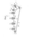
- FIG. 3 is a perspective view showing a basic configuration of the transfer belt unit 40 according to the first embodiment.
- FIG. 4 is a sectional view taken along line IV-IV in FIG. 3 .
- the transfer belt unit 40 is configured so that the intermediate transfer belt 41 is stretched around three rollers: the driving roller 42, the tension roller 43 and the backup roller 43 as described above.
- the driving roller 42 rotates to move the intermediate transfer belt 41e.
- the tension roller 43 has a tension roller shaft 43a whose inclination can be changed as described later.
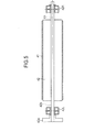
- FIG. 5 shows the driving roller 42.
- the driving roller 42 has a driving roller shaft 42b.
- the driving roller shaft 42b is rotatably supported by bearings 42L and 42R mounted to frames 51L and 51R ( FIG. 3 ) of the transfer belt unit 40.
- a driving gear 42a is fixed to the driving roller shaft 42b.
- a power of the driving motor 110 is transmitted to the driving gear 42a, and the driving roller 42 (with the driving roller shaft 42b and the driving gear 42a) rotates about a rotation axis O1 as a second rotation axis.
- the driving roller 42 is a metal roller made of aluminum covered with a ceramic coating layer.
- the driving roller 42 rotates, the intermediate transfer belt 41 rotates due to a friction between the driving roller 42 and the intermediate transfer belt 41.
- the backup roller 44 is located on a downstream side of the driving roller 42 in the belt conveying direction X.
- the backup roller 44 is made of aluminum, and is rotatably supported by the bearings 45L and 45R mounted to the frames 51L and 51R ( FIG. 3 ).
- the tension roller 43 is located on a downstream side of the backup roller 44 in the belt conveying direction X.
- the tension roller 43 has the tension roller shaft 43a rotatable about a rotation axis 02 as a first rotation axis.
- the tension roller 43 is divided into a plurality of (for example, five) roller parts 43-1, 43-2, 43-3, 43-4 and 43-5 in an axial direction of the tension roller shaft 43a. That is, the tension roller 43 as the first rotation member includes a plurality of roller parts 43-1, 43-2, 43-3, 43-4 and 43-5 as a plurality of divided rollers (or segment rollers) in the axial direction of the rotation axis 02 of the tension roller shaft 43a.
- FIG. 6 is a perspective view showing the roller part 43-1 among the roller parts 43-1 through 43-5 of the tension roller 43 of FIG. 3 .
- the roller parts 43-1 through 43-5 have engaging holes (i.e., center holes) through which the tension roller shaft 43a penetrates.
- roller parts 43-1 through 43-5 are independently rotatable about the tension roller shaft 43a. Further, the roller parts 43-1 through 43-5 are mounted to the tension roller shaft 43a using e-rings 58 so as not to move in the axial direction of the tension roller shaft 43a ( FIGS. 7A, 7B and 7C ).
- FIGS. 7A, 7B and 7C are sectional views taken along line VII-VII in FIG. 3 .
- a pulley 56 as a third rotation member is mounted to an end of the tension roller shaft 43a.
- the pulley 56 has a flange portion 56b as a contact portion (i.e., a belt contact portion) with a surface A that contacts a lateral end (i.e., a widthwise end) of the intermediate transfer belt 41.
- the pulley 56 has a engaging hole 56 through which the tension roller shaft 43a penetrates.
- the pulley 56 is slidable along the tension roller shaft 43a, i.e., movable in the direction of the rotation axis 02.
- the pulley 56 has a surface B opposite to the surface A.
- the surface B of the pulley 56 contacts a lever 55 (as a shaft shifting member).
- the lever 55 is mounted to the frame 51L so as to be rotatable about a rotation axis 03 as a third rotation axis inclined with respect to the rotation axis 02.
- a bearing 54L is provided on the same end of the tension roller shaft 43a as the pulley 56.
- an arm 52 is rotatably mounted to the frame 51L so as to be rotatable about a rotation axis 52a.
- the bearing 54L is mounted in a rail portion 52b formed on the arm 52 so as to be slidable in a longitudinal direction of the rail portion 52b.
- a spring 53L is provided between the bearing 54L and an inner wall of the rail portion 52b of the arm 52.
- the spring 53L is constituted by a compression coil spring, and presses the bearing 54L to apply a tension to the intermediate transfer belt 41.
- a bearing 54R is provided on an end of the tension roller shaft 43a opposite to the pulley 56.
- the bearing 54R is slidably mounted in a rail portion (not shown) formed on the frame 51R.
- a spring 53R ( FIG. 4 ) is provided between the bearing 54R and an inner wall of the rail portion of the frame 51R ( FIG. 2 ).
- the spring 53R is constituted by a compression coil spring, and presses the bearing 54R to apply a tension to the intermediate transfer belt 41.
- a belt regulation roller pair 57 as a belt regulating unit is provided on a downstream side of the tension roller 43 in the belt conveying direction X.
- the belt regulation roller pair 57 includes rollers 57a and 57b provided so as to nip the intermediate transfer belt 41 therebetween. Both ends of the roller 57a are rotatably supported by not shown bearings mounted to the frame 51L and 51R. Similarly, both ends of the roller 57b are rotatably supported by not shown bearings mounted to the frame 51L and 51R.
- the rollers 57a and 57b regulate a trajectory of movement of the intermediate transfer belt 41.
- the transfer rollers 14 (14C, 14M, 14Y, 14K) as first primary transfer members are provided on a downstream side of the belt regulation roller pair 57 in the belt conveying direction X.
- Each of the transfer rollers 14 is rotatably supported by not shown bearings mounted to the frames 51L and 51R.
- the transfer rollers 14 are pressed against the OPC drums 31C, 31M, 31Y and 31K via the intermediate transfer belt 41 by a pressing unit (not shown).
- an e-ring 58 and a spacer 59 are provided between the roller part 43-5 and the bearing 54R. Further, another e-ring 58 is provided between the roller part 43-1 and the bearing 54L.
- the e-rings 58 and the spacer 59 constitute a regulating member that regulates the axial movement of the roller parts 43-1 through 43-5 in the axial direction of the tension roller 43.
- the pulley 56 has the flange portion 56b that contacts the lateral end of the intermediate transfer belt 41 as described above.
- the lever 55 contacts the surface B of the pulley 56 opposite to the intermediate transfer belt 41.
- the lever 55 is mounted to the frame 51L so as to be rotatable about the rotation axis 03 as the third rotation axis.
- the roller parts 43-1, 43-2, 43-3, 43-4 and 43-5 of the tension roller 43 are rotatably supported by the tension roller shaft 43a. Gaps "d" are formed between adjacent roller parts 43-1 through 43-5 in the axial direction of the rotation axis 02 of the tension roller 43 so as to suppress generation of a friction force.
- the gaps "d" are formed by providing ring-shaped boss portions 43b (i.e., abutting portions) on the roller parts 43-1 through 43-5.
- Each boss portion 43b has a smaller diameter than a belt stretching portion 43c (of each tension roller 43) around which the intermediate transfer belt 41 is stretched.
- the boss portions 43b of the respective roller parts 43-1 through 43-4 abut against to-be-abutted portions 43d of the adjacent roller parts 43-2 through 43-5.
- the roller parts 43-1 through 43-5 have the same shapes in order to contribute to reducing manufacturing cost. Therefore, the roller parts 43-1 through 43-5 have the boss portions 43b (i.e., the abutting portions) on the same side, which abut against the to-be-abutted portions 43d of the adjacent roller part.
- this embodiment is not limited to such a configuration.
- each of the roller parts 43-2 and 43-4 has two boss portions 43b on both sides, and each of the roller parts 43-1, 43-3 and 43-5 has two to-be-abutted portions 43d on both sides. With such a configuration, the above described gap "d" can be formed between the adjacent roller parts 43-1 through 43-5, and therefore generation of a friction force can be suppressed.
- the tension roller 43 is supported by engagement of the tension roller shaft 43a and the bearings 54L and 54R.
- the tension roller 43 is prevented from moving toward the bearing 54R by the e-ring 58 and the spacer 59. Further, the tension roller 43 is prevented from moving toward the bearing 54L by the e-ring 58.
- the bearings 54L and 54R have self-aligning function, and are configured to follow the inclination of the tension roller 43.
- FIG. 8 is an enlarged view showing a configuration at the end of the tension roller 43 on the pulley 56 side.
- the rotation axis 02 of the tension roller 43 is inclined downward with respect to the rotation axis O1 of the driving roller 42 as shown in FIG. 7C .
- the lever 55 rotates about the rotation axis 03 in a direction shown by an arrow "a", and presses the pulley 56 in a direction shown by an arrow D2.
- the flange portion 56b (i.e., the contact portion) of the pulley 56 has a tapered portion 56a.
- the tapered portion 56a guides the intermediate transfer belt 41 to its original position.
- FIGS. 9A, 9B and 9C are perspective views showing an operation of the configuration at the end of the tension roller 43.
- FIG. 9B shows a state in which the rotation axis 02 of the tension roller 43 is parallel to the rotation axis O1 of the drive roller 42 as shown in FIG. 7B .
- the intermediate transfer belt 41 moves stably.
- FIG. 9A shows a state in which the rotation axis 02 of the tension roller 43 is inclined upward with respect to the rotation axis 01 of the driving roller 42 as shown in FIG. 7A .
- the lever 55 rotates about the rotation axis 03 ( FIG. 8 ), and contacts the arm 52.
- FIG. 9C shows a state in which the rotation axis 02 of the tension roller 43 is inclined downward with respect to the rotation axis O1 of the driving roller 42 as shown in FIG. 7C .
- the lever 55 rotates about the rotation axis 03 ( FIG. 8 ) to press the pulley 56, so that the intermediate transfer belt 41 and the tension roller 43 are moved toward the bearing 54R.
- FIG. 10 is a perspective view showing the configuration at the end of the tension roller 43 shown in FIGS. 9A through 9C .
- the lever 55 has the rotation axis 03 inclined at a predetermined angle with respect to the rotation axis 02 of the tension roller 43.
- the lever 55 has an elongated hole 55a of substantially oval shape.
- the tension roller shaft 43a (omitted in FIG. 10 ) penetrates the elongated hole 55a, and is rotatably and slidably held in the elongated hole 55a.
- the lever 55 has convex portions 55b facing the pulley 56, and the convex portions 55b are able to contact the pulley 56.
- the above described bearing 54L and the spring 53L are provided in the rail portion 52b of the arm 52.
- the lever 55 has the rotation axis 03 inclined with respect to the rotation axis 02 of the tension roller 43. Therefore, when the left end (i.e., the pulley 56 side) of the tension roller 43 is shifted downward as shown in FIG. 7C , the lever 55 rotates downward and toward the tension roller 43, and presses the pulley 56.
- FIGS. 11A, 11B, 11C and 11D are schematic views for illustrating the skew of the intermediate transfer belt 41 shown in FIG. 4 .
- FIGS. 11A and 11C are plan views schematically showing a trajectory Xt of the intermediate transfer belt 41 together with the driving roller 42 and the tension roller 43.
- FIGS. 11A and 11C Left and right sides are reversed with respect to FIGS. 7A through 7C .
- FIGS. 11B and 11D are side views schematically showing a trajectory Xt of the intermediate transfer belt 41 together with the driving roller 42 and the tension roller 43.
- the intermediate transfer belt 41 is moved (rotated) by the driving roller 42 in the belt conveying direction X. If the driving roller 42, the tension roller 43 an the backup roller 43 are not exactly parallel to one another, the intermediate transfer belt 41 may skew in a direction perpendicular to the belt conveying direction X when the intermediate transfer belt 41 moves.
- the intermediate transfer belt 41 moves along the trajectory Xt shown in FIG. 11A due to tendency of the intermediate transfer belt 41 to move perpendicularly to the axial direction of the tension roller 43.
- the intermediate transfer belt 41 skews in a belt skew direction Y1 perpendicular to the belt conveying direction X.
- the driving roller 43 By one rotation of the driving roller 43, the intermediate transfer belt 41 skews in the belt skew direction Y1 by an amount "m" shown in FIG. 11A .
- a solid line indicates the trajectory Xt above the driving roller 42 and the tension roller 43
- a dashed line indicates the trajectory Xt below the driving roller 42 and the tension roller 43.
- the skew of the intermediate transfer belt 41 is caused by a non-parallelism of the driving roller 42, the tension roller 43 and the backup roller 44, an unevenness of the tension of the intermediate transfer belt 41 (for example, a difference in biasing force between springs 53L and 53R at both ends of the tension roller shaft 43a), a difference in circumferential length between both lateral ends of the intermediate transfer belt 41, a cylindricality of each of the rollers around which the intermediate transfer belt 41 is stretched (i.e., the driving roller 42, the tension roller 43 and the backup roller 44), and the like.
- the image forming control unit 100 of the image forming apparatus receives image data from the host device 10A via the I/F control unit 101, and starts an image forming operation.
- the image forming control unit 100 causes the feeding-conveying control unit 109 to drive the feeding motor 115.
- the pickup roller 12a of the medium feeding unit 12 is driven by the feeding motor 115, and picks up the recording medium P from the medium tray 11.
- the recording medium P picked up by the pickup roller 12a reaches a nip portion between the feeding roller 12b and the retard roller 12c, and is separately fed.
- the recording medium P fed by the medium feeding unit 12 then reaches the medium conveying unit 13, and conveyed by the conveying roller pairs 13a, 13b and 13c to reach the transfer roller 15 as the secondary transfer portion.
- the charging rollers 32 (32C, 32M, 32Y, 32K) are applied with negative voltage (for example, -1000V) by the charge voltage control unit 102, and charge the surfaces of the OPC drums 31 (31C, 31M, 31Y, 31K) to negative potential (for example, -600V).
- the head control unit 103 causes the printing heads 33 (33C, 33M, 33Y, 33K) to expose the surfaces of the OPC drums 31 (31C, 31M, 31Y, 31K) according to the image data sent from the host device 10A so as to form latent images on the OPC drums 31.
- the developing rollers 34 are applied with negative voltage (for example, -200V) by the developing voltage control unit 104, and develop the latent images on the OPC drums 31 (31C, 31M, 31Y, 31K) using the toners supplied by the toner supply units 35 (35C, 35M, 35Y, 35K) so as to form toner images (i.e., visualized images) as developer images.
- the transfer rollers 14 as the primary transfer portions are applied with positive voltage (for example, +1500V) by the primary transfer voltage control unit 105.
- the toner images formed on the OPC drums 31 are transferred to the intermediate transfer belt 41 at the nip portions between the OPC drums 31 and the transfer rollers 14, so that the charged toner image is formed on the intermediate transfer belt 41.
- the backup roller 44 is connected to a frame ground (i.e., grounded).
- the OPC drums 31 of the toner image forming units 30 (30C, 30M, 30Y, 30K) and the intermediate transfer belt 41 are driven in synchronization with each other under control of the image forming control unit 100, and toner images of the respective colors are transferred to the intermediate transfer belt 41.
- the toner image formed on the intermediate transfer belt 41 is carried to the transfer roller 15 as the secondary transfer portion by the intermediate transfer belt 41.
- the transfer roller 15 is applied with positive voltage (for example, +3000V) by the secondary transfer voltage control unit 106.
- the toner image is transferred from the intermediate transfer belt 41 to the recording medium P by electric field formed by the transfer roller 15 and the grounded backup roller 44.
- the recording medium P (to which the toner image has been transferred by the transfer roller 15) is conveyed to the fixing portion 16.
- the fixing portion 16 applies heat and pressure to the recording medium P so as to melt and fix the toner image to the recording medium P. Then, the recording medium P is ejected by the ejection roller pairs 17a, 17b and 17c to the stacker portion 18.
- the tension roller 43 is inclined as shown in FIG. 7C , due to flatness of an installation surface of the image forming apparatus 10, a deflection of the frames 51L and 51R, an assembly error, a dimensional error or the like.
- the tension roller shaft 43a of the tension roller 43 is also inclined, and therefore the lever 55 (with the elongated hole 55a through which the tension roller shaft 43 penetrates) contacts the tension roller shaft 43 at a position E1 on a periphery of the elongated hole 55a.
- the lever 55 is applied with a force in a direction shown by an arrow D1 (i.e., downward) at the position E1. Therefore, the lever 55 rotates in a direction indicated by an arrow "a" about the rotation axis 03 fixed to the frame 51L.
- the pulley 56 is provided between the lever 55 and the tension roller 43 so as to be movable along the tension roller 43a in the axial direction.
- the lever 55 rotates in the direction indicated by the arrow "a"
- the lever 55 contacts the pulley 56 at the position E2.
- the lever 55 applies a force to the pulley 56 in a direction indicated by an arrow D2. Therefore, the pulley 56 slides along the tension roller shaft 43a substantially in the direction indicated by the arrow D2.
- the intermediate transfer belt 41 contacts the flange portion 56b of the pulley 56 at a position E3.
- the intermediate transfer belt 41 is applied with a force in a direction indicated by an arrow D3 at the position E3. Therefore, the intermediate transfer belt 41 is moved toward the bearing 54R side.
- the intermediate transfer belt 41 and the tension roller 43 rotate accompanying the rotation of the driving roller 42. Accordingly, the intermediate transfer belt 41 skews in the belt skew direction Y2 (see FIG. 11C ), and the intermediate transfer belt 41 presses the pulley 56 having the flange 56b contacting the lateral end of the intermediate transfer belt 41 at the positions E3 and E4 as shown in FIG. 8 .
- the intermediate transfer belt 41 presses the pulley 56 with a force F in a direction opposite to the direction D3.
- the pulley 56 slides along the tension roller shaft 43a in the axial direction, i.e., the belt skew direction Y2.
- the lever 55 is pressed in a direction opposite to the direction D2, and the lever 55 rotates in a direction indicated by an arrow b.
- the tension roller shaft 43a is pressed by the elongated hole 55a of the lever 5 to move in a direction (i.e., upward) opposite to the direction D1.
- the arm 52 ( FIG. 3 ) supporting the bearing 54L rotates in a direction indicated by an arrow f about the rotation axis 52a, and the bearing 54L moves toward a position shown in FIG. 7B .
- the intermediate transfer belt 41 stably moves in the state shown in FIG. 7B .
- the intermediate transfer belt 41 stably moves in a state where weights of the intermediate transfer belt 41 and the arm 52, friction forces between the respective parts and the like are balanced.
- rotation axis 02 of the tension roller 43 is substantially parallel to the rotation axis O1 of the driving roller 42. Therefore, if the rotation axis O1 of the driving roller 42 is parallel to the rotation axis of the backup roller 44, the skew of the intermediate transfer belt 41 decreases, and the intermediate transfer belt 41 stably moves in the state shown in FIG. 7B .
- the inclination operation of the tension roller 43 has been described with reference the operation from FIG. 7C to FIG. 7B (i.e., case 1), and the operation from FIG. 7A to FIG. 7B (i.e., case 2). Regardless of the direction in which the tension roller 43 is inclined, the lever 55 causes the tension roller 43 to be inclined so as to correct the skew of the intermediate transfer belt 41.
- the intermediate transfer belt 41 is brought into a state where the intermediate transfer belt 41 stably moves (without skew) due to thrust forces acting on the pulley 56 and the lateral end of the intermediate transfer belt 41 in the belt skew directions Y1 and Y2, once the intermediate transfer belt 41 starts to move.
- the rotation axis 02 of the tension roller 43 and the rotation axis O1 of the driving roller 42 and the rotation axis of the backup roller 44 become substantially parallel, and the skew of the intermediate transfer belt 41 is reduced, with the result that the intermediate transfer belt 41 stably moves without skew.
- the lateral end of the intermediate transfer belt 41 and the pulley 56 can be kept in contact with each other with a small contact force.
- the axial direction of the tension roller 43 (which is the same as the widthwise direction of the intermediate transfer belt 41) will be also referred to as a widthwise direction.
- FIG. 12 is a schematic view showing a state of the inner circumferential surface of the intermediate transfer belt 41 and the outer surface of the tension roller 43 when the tension roller 43 is inclined.
- the tension roller 43 of FIG. 12 is not divided into a plurality of roller parts.
- the tension roller 43 When the tension roller 43 is inclined about a inclination center (i.e., fulcrum) O1a, the tension roller 43 is rotated by contact with the inner circumferential surface of the intermediate transfer belt 41. Since the tension roller 43 has a length extending over a large portion of the width of the intermediate transfer belt 41, a slippage occurs between the outer surface of the tension roller 43 and the inner circumferential surface of the intermediate transfer belt 41.
- FIG. 13 is a schematic view showing a state where a slippage occurs at the widthwise center R2C of the tension roller 43 in such a manner that the outer surface of the tension roller 43 rotates relative to the inner circumferential surface of the intermediate transfer belt 41.
- the tension roller 43 of FIG. 13 is not divided into a plurality of roller parts.
- a width of a roller body (i.e., except the tension roller shaft 43a) of the tension roller 43 is expressed as B.
- the friction force between the outer surface of the driving roller 43 and the inner circumferential surface of the intermediate transfer belt 41 per unit length is expressed as S.
- a stretching force and a friction force applied to the tension roller 43 in the width direction due to the tension of the intermediate transfer belt 41 are both constant.
- a moment generated at the widthwise center R2C of the tension roller 43 is expressed as Mc.
- a moment generated at a center 03a (i.e., right end center 03a) at the right end of the tension roller 43 is expressed as Ms.
- the right end center 03a is an inclination center of the tension roller 43.
- a friction force between the outer surface of the tension roller 43 and the inner circumferential surface of the intermediate transfer belt 41 is expressed as F.
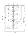
- FIG. 14 is a schematic view showing a state where friction forces are generated at widthwise centers R3-1, R3-2, R3-3, R3-4 and R3-5 of the respective roller parts 43-1, 43-2, 43-3, 43-4 and 43-5 in such a manner that the outer surfaces of the roller parts 43-1 through 43-5 rotate relative to the inner circumferential surface of the intermediate transfer belt 41.
- the tension roller 43 divided into the roller parts 43-1 through 43-5 is inclined about the right end center 03a as was described with reference to FIGS. 12 and 13 .
- the outer surfaces of the roller parts 43-1 through 43-5 rotate without slippage on the inner circumferential surface of the intermediate transfer belt 41 at the widthwise centers of the roller parts 43-1 through 43-5.
- slippages occur between the outer surfaces of the respective roller parts 43-1 through 43-5 and the inner circumferential surface of the intermediate transfer belt 41 in such a manner that the outer surfaces of the roller parts 43-1 through 43-5 rotate about the widthwise centers R3-1 through R3-5.
- a width of the roller body (i.e., the roller parts 43-1 through 43-5) of the tension roller 43 is expressed as B.
- a division number i.e., the number of roller parts
- S A friction force between the outer surface of the driving roller 43 and the inner circumferential surface of the intermediate transfer belt 41 per unit length.
- a stretching force and a friction force applied to the tension roller 43 in the width direction due to the tension of the intermediate transfer belt 41 are both constant.
- Moments generated at the widthwise centers R3-1, R3-2, R3-3, R3-4 and R3-5 of the roller parts 43-1 through 43-5 are expressed as Mc.
- a moment generated by the moments Mc at the right end center 03a (assumed to the inclination center of the tension roller 43) is expressed as Ms. Friction forces between the outer surfaces of the roller parts 43-1 through 43-5 and the inner circumferential surface of the intermediate transfer belt 41 are expressed as F.
- This friction force F is generated at left and right portions each at a distance r from each of the widthwise centers R3-1 through R3-5, assuming that the friction force is evenly distributed in the widthwise direction.
- N the division number (i.e., the number of roller parts of the tension roller 43).
- the moment Ms can be reduced by approximately 36% as compared with when the division number t is 1.
- Table 1 shows the moments Ms for the division numbers 1 to 10 determined based on the equation (7), as compared to 100% for the moment Ms when the division number t is 1. TABLE 1. DIVISION NUMBER t MOMENT Ms (%) 1 100 2 67 3 51 4 42 5 36 6 31 7 28 8 25 9 23 10 21
- FIG. 15 is a graph showing a relationship between the division number t of the tension roller 43 and the ratio of the moment Ms caused by the friction.
- a horizontal axis indicates the division number t.
- a vertical axis indicates a ratio of the moment Ms (for the division numbers 1 to 10) with respect to the moment Ms (100%) for the division number 1.
- a point of inflection of a curve of the ratio of the moment Ms is located in the vicinity of a point where the division number t is 3.3. This means that the effect of the first embodiment is more effectively achieved when the division number t is greater than or equal to 4.
- the effect of the first embodiment is achieved more effectively as the division number (t) increases.
- the width of the each of the roller parts 43-1 through 43-5 of the tension roller 43 is greater than or equal to 30 mm. This is because, if the width of the roller part is less than 30 mm, there is a possibility that a backlash may occur between the tension roller 43 and the tension roller shaft 43a and may increase a load on the tension roller 43.
- the upper limit of the division number t is determined by a maximum sheet size of the recording medium P used in the image forming apparatus 10. For example, if the maximum sheet size of the recording medium P used in the image forming apparatus 10 is A3 size, the width L of the tension roller 43 is determined to be approximately equal to the sheet width of 297 mm plus 40 mm. If the maximum sheet size of the recording medium P used in the image forming apparatus 10 is A4 size, the width L of the tension roller 43 is determined to be approximately equal to the sheet width of 210 mm plus 40 mm.
- the division number t of the tension roller 43 is preferably less than or equal to 10.
- the division number t of the tension roller 43 is preferably less than or equal to 8.
- the division number t of the tension roller 43 is preferably in a range from 4 to 10.
- the division number t of the tension roller 43 is preferably in a range from 4 to 8.
- the tension roller 43 is divided in the axial direction into a plurality of roller parts 43-1 through 43-5, it becomes possible to reduce the load on the tension roller 43 due to the friction between the outer surface of the tension roller 43 and the inner circumferential surface of the intermediate transfer belt 41 during the inclination operation.
- the friction force between the tension roller 43 and the intermediate transfer belt 41 is dispersed, the contact force between the flange portion 56b and the intermediate transfer belt 41 becomes constant. Therefore, when the intermediate transfer belt 41 is guided to a stable position by the flange portion 56b of the pulley 56 (in the case where the intermediate transfer belt 41 skews), it becomes possible to prevent the intermediate transfer belt 41 from being deformed by excessive load to pass over the flange 56b.
- the tension roller 43 is divided in the axial direction into a plurality of the roller parts 43-1 through 43-5, and the roller parts 43-1 through 43-5 are independently rotatable. Therefore, it becomes possible to reduce the friction between the outer surface of the tension roller 43 and the inner circumferential surface of the intermediate transfer belt 41 during the inclination operation. Accordingly, the tension roller 43 can smoothly perform the inclination operation with small load. Thus, the contact force (stress) between the lateral end of the intermediate transfer belt 41 and the pulley 56 can be reduced. As a result, a lifetime of the transfer belt unit 40 can be lengthened.
- FIGS. 16A and 16B are schematic views showing the tension roller 43 according to the first embodiment and a tension roller 43A (as a first rotation member) according to the second embodiment of the present invention both in assembled state.
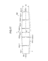
- FIG. 17 shows the tension roller 43A of the second embodiment shown in FIG. 16B .
- the transfer belt unit of the second embodiment is the same as the transfer belt unit 40 of the first embodiment except the tension roller 43 (43A).
- the tension roller 43 (the roller parts 43-1 through 43-5) of the first embodiment has a straight shape. That is, the outer diameter G1 at the center of the tension roller 43 is the same as the outer diameter G1 at the end of the tension roller 43.
- the outer diameter G3 at the center of the tension roller 43A (the roller parts 43A-1 through 43A-5) is larger than the outer diameter G2 at both ends of the tension roller 43A.
- the tension roller 43A of the second embodiment has a crown shape such that the outer diameter G3 at the center of the tension roller 43A is slightly larger than the outer diameter G2 at both end of the tension roller 43A.
- a difference between the outer diameters G2 and G3 at both ends of the tension roller 43 is determined taking into consideration a deflection of the tension roller shaft 43a caused when the tension is applied to the intermediate transfer belt 41 by the springs 53L and 53R.
- the tension roller shaft 43a penetrates through the roller parts 43A-1 through 43A-5 of the tension roller 43A to rotatably support.
- the roller parts 43A-1 through 43A-5 have ring-shaped boss portions 43Ab-1, 43Ab-2, 43Ab-3, 43Ab-4 and 43Ab-5, and form gaps 43Ad between adjacent roller parts 43A-1 through 43A-5.
- the outer diameter G2 at both ends of the tension roller 43A is smaller than the outer diameter G3 at the center of the tension roller 43A as described above.
- the roller parts 43Ab-1 through 43Ab-5 do not interfere with each other, even when the tension roller shaft 43a is deflected by a force as shown by an arrow E. Further, when the deflection of the tension roller shaft 43a occurs, outer surfaces of the roller parts 43Ab-1 through 43Ab-5 on a side opposite to the driving roller 42 (shown by a line F in FIG. 17 ) are aligned substantially straightly as shown in FIG. 16B .
- the tension roller 43 of FIG. 16 has a straight shape and is divided into a plurality of roller parts, as was described in the first embodiment.
- tension roller shaft 43a is deflected due to the tension of the intermediate transfer belt 41 applied by the springs 53L and 53R, there arises a difference between a stretching force T1 (per unit width) at the end of the tension roller 43 and a stretching force T2 (per unit width) at the center of the tension roller 43.
- the tension roller 43 ( FIG. 16A ) is divided into a plurality of roller parts, a bending strength of the tension roller 43 as a whole is relatively low. Therefore, the difference between the stretching forces T1 and T2 becomes relatively large. Depending on the strength of the tension roller shaft 43a and the spring forces of the springs 53L and 53R, large stretching forces may be intensively generated at the ends of the tension roller 43. In such a case, a tensile stress at the lateral end of the intermediate transfer belt 41 in the circumferential direction may increase, and the lifetime of the intermediate transfer belt 41 may be reduced.
- the outer diameter G2 at both ends of the tension roller 43A (the roller parts 43A-1 through 43A-5) is smaller than the outer diameter G3 at the center of the tension roller 43A as described above. Therefore, as shown in FIG. 16B , it becomes possible to reduce a difference between a stretching force T3 (per unit width) at the end of the tension roller 43A and a stretching force T4 (per unit width) at the center of the tension roller 43A.
- the tension roller 43A is divided into a plurality of roller parts, and has a shape such that the outer diameter G3 at the center is larger than the outer diameter G2 at the end. Therefore, the stretching force T3 (per unit width) at the end of the tension roller 43A can be reduced, and a difference between the stretching force T3 at the end of the tension roller 43A and the stretching force T4 at the center of the tension roller 43A can be reduced. Accordingly, the intermediate transfer belt 41 becomes able to smoothly move. Further, since the tensile stress at the lateral ends of the intermediate transfer belt 41 can be reduced, the lifetime of the transfer belt unit 40 can be lengthened.
- the belt driving device is used as the transfer belt unit 40 employed in the electrophotographic printer.
- the belt driving deice of the present invention can be employed in other image forming apparatuses such as a copier, a facsimile machine or the like that form an image on the recording medium using electrophotography.
- the belt driving device is employed in the image forming apparatus 10 of the intermediate transfer type that forms a developer image on the intermediate transfer belt 41 and transfers the developer image to the recording medium P.
- the belt driving device of the present invention can be applicable to a direct transfer type image forming apparatus that forms a developer image on the OPC drum 31, and directly transfer the developer image from the OPC drum to the recording medium P.
- the belt driving device is used as the transfer belt unit 40 employed in the electrophotographic image forming apparatus.
- the belt driving deice of the present invention can also be employed in a fixing unit and a medium conveying device using an endless belt.
- the belt driving device of the present invention can be used for other purposes than the electrophotographic image forming apparatus as long as an endless belt (i.e., a stretched member) is used.
- the endless belt (more specifically, the intermediate transfer belt) has been described as an example of a stretched member.
- stretched members such as an ended (i.e., non-endless) belt, an endless sheet, an ended sheet or the like.
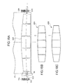
- FIG. 18A shows a tension roller 43B according to a modification of the second embodiment.
- the tension roller 43A of the second embodiment (see FIGS. 16B and 17 ) has the crown shape
- the tension roller 43B of this modification ( FIG. 18 ) has a tapered shape, and the outer diameter gradually increases from each end toward the center of the tension roller 43B in such a manner that a difference between diameters at opposing ends of adjacent roller parts is minimized.
- FIG. 18B schematically shows the crown shape of the tension roller 43A of the second embodiment ( FIGS. 16B and 17 ), and FIG. 18C schematically shows the tapered shape of the tension roller 43B of the modification ( FIG. 18A ).
- the tension roller 43A of the second embodiment has the crown shape whose outer periphery has a continuous smooth curve C along the axial direction.
- the tension roller 43B of the modification has a tapered shape whose outer periphery includes a plurality of straight tapers T. If the tension roller 43B includes odd number of roller parts, the center roller part has a cylindrical shape.
- tension roller 43 in the first and second embodiments can also be applied to the backup roller 44 and/or the driving roller 42.
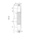
- FIG. 19 shows a modification in which the feature ( FIGS. 16B and 17 ) of the second embodiment is applied to the driving roller 42.
- the driving roller 42A shown in FIG. 19 is divided into a plurality of roller parts. More specifically, the driving roller 42A is divided into a roller part 40c at the center of the driving roller 42, and roller parts 40d on both sides of the roller part 40c.
- the roller part 40c is fixed to a driving roller shaft 42b, and has a circumferential surface of high friction.
- the roller parts 40d are rotatably supported by the driving roller shaft 42b, and each roller part 40d has a tapered shape such that the outer diameter increases toward the roller part 40c.
- FIGS. 20A and 20B are enlarged views showing modifications of configurations at the end portion of the tension roller 43.
- a reinforcing member 41a can be provided at the lateral end of the intermediate transfer belt 41.
- a guide member 41b can be provided on the inner circumferential surface at the lateral end of the intermediate transfer belt 41.
- the pulley 56 is provided with a groove 56c engaging the guide member 41b.
Abstract
Description
- The present invention relates to a driving device in which a stretched member (for example, as an endless belt) is stretched around a plurality of rollers and moved by the rollers, and an image forming apparatus using the driving device.
- There has been proposed a technology for preventing the skew of the endless belt (Japanese Laid-open Patent Publication No.
2006-162659 - However, although the prior art is capable of preventing the skew of the endless belt, a lengthening of a lifetime of the endless belt (i.e., the stretched member) is not sufficiently achieved.
- The present invention is intended to solve the above described problems, and an object of the present invention to provide a driving device and an image forming apparatus capable of lengthen a lifetime of a stretched member.
- According to an aspect of the present invention, there is provided a driving device including a stretched member, and a first rotation member and a second rotation member around which the stretched member is stretched. The first rotation member has a first rotation axis, and the second rotation member has a second rotation axis. The first rotation member includes a plurality of members arranged in an axial direction of said first rotation axis.
- With such a configuration, a lifetime and reliability of the stretched member can be enhanced.
- According to another aspect of the present invention, there is provided an image forming unit including the above described driving device.
- Further scope of applicability of the present invention will become apparent from the detailed description given hereinafter. However, it should be understood that the detailed description and specific embodiments, while indicating preferred embodiments of the invention, are given by way of illustration only, since various changes and modifications within the spirit and scope of the invention will become apparent to those skilled in the art from this detailed description.
- In the attached drawings:
-
FIG. 1 is a schematic sectional view showing a configuration of an image forming apparatus according to the first embodiment of the present invention; -
FIG. 2 is a block diagram showing a control system of the image forming apparatus according to the first embodiment; -
FIG. 3 is a perspective view showing a transfer belt unit according to the first embodiment; -
FIG. 4 is a sectional view of the transfer belt unit taken along line IV-IV inFIG. 3 ; -
FIG. 5 is a sectional view showing a driving roller according to the first embodiment; -
FIG. 6 is a perspective view showing a roller part of a tension roller according to the first embodiment; -
FIGS. 7A, 7B and 7C are sectional views of the tension roller taken along line VII-VII inFIG. 4 ; -
FIG. 8 is an enlarged view showing a configuration at an end of the tension roller according to the first embodiment; -
FIGS. 9A, 9B and 9C are schematic views showing an operation of the configuration at the end of the tension roller according to the first embodiment; -
FIG. 10 is an exploded perspective view showing the configuration at the end of the tension roller according to the first embodiment; -
FIGS. 11A, 11B, 11C and 11D are schematic views for illustrating a skew of an intermediate transfer belt; -
FIG. 12 is a schematic view showing an inclination operation of a tension roller; -
FIG. 13 is a schematic view showing the inclination operation of the tension roller; -
FIG. 14 is a schematic view showing the inclination operation of the tension roller according to the first embodiment; -
FIG. 15 is a graph showing a relationship between a division number of the tension roller and a moment ratio; -
FIGS. 16A and 16B are plan views showing a tension roller according to the second embodiment of the present invention; -
FIG. 17 is a plan view showing the tension roller according to the second embodiment; -
FIG. 18A is a plan view showing a modification of the tension roller of the second embodiment; -
FIG. 18B is a schematic view showing a shape of the tension roller ofFIG. 17 ; -
FIG. 18C is a schematic view showing a shape of the tension roller ofFIG. 18A ; -
FIG. 19 is a plan view showing a modification of the driving roller to the second embodiment, and -
FIGS. 20A and 20B are enlarged views showing a modification of a configuration at the end of the tension roller of the second embodiment. - Hereinafter, embodiments of the present invention will be described with reference to drawings.
-
FIG. 1 is a schematic view showing a configuration of animage forming apparatus 10 according to the first embodiment of the present invention. - The
image forming apparatus 10 is configured as, for example, an electrophotographic printer of an intermediate transfer type. Theimage forming apparatus 10 includes amedium tray 11 in which recording media (for example, sheets) P are stored. Amedium feeding unit 12 is provided on a feeding side (i.e., left side inFIG. 1 ) of themedium tray 11. Themedium feeding unit 12 is configured to feed the recording medium P one by one out of themedium tray 11. Themedium feeding unit 12 includes apickup roller 12a pressed against the topmost recording medium P lifted to a predetermined height. Themedium feeding unit 12 further includes afeeding roller 12b and aretard roller 12c for separately feeding the recording medium P picked up by thepickup roller 12a. Amedium conveying unit 13 is provided on a downstream side of themedium feeding unit 12 in a conveying direction of the recording medium P. Themedium conveying unit 13 includes a plurality of conveyingroller pairs transfer roller 15 described later. - An
image forming portion 20 includes four toner image forming units 30 (30C, 30M, 30Y and 30K) as developer image forming units, four transfer rollers 14 (14C, 14M, 14Y and 14K), and atransfer roller 15. The tonerimage forming units 30 are arranged in tandem, and respectively form toner images (i.e., developer images). The transfer rollers 14 are configured to primarily transfer the toner images to anintermediate transfer belt 41 described later. Thetransfer roller 15 is configured to secondarily transfer the toner image from theintermediate transfer belt 41 to the recording medium P. Therefore, the transfer rollers 14 are also referred to as primary transfer rollers, and thetransfer roller 15 are also referred to as a secondary transfer roller. - The toner
image forming units 30 include OPC (Organic Photo Conductor) drums 31 (31C, 31M, 31Y, 31K) as image bearing bodies that bear toner images, charging rollers 32 (32C, 32M, 32Y, 32K) as charging members that negatively charge the surfaces of theOPC drums 31, printing heads 33 (33C, 33M, 33Y, 33K) as exposure units that expose the surfaces of theOPC drums 31 to form latent images, developing rollers 34 (34C, 34M, 34Y, 34K) as developing members that develop the latent images to form toner images, and developer supply units 35 (35C, 35M, 35Y and 35K) that supply toners to the developingrollers 34. Theprinting heads 33 are constituted by, for example, LED (Light Emitting Diode) arrays. - A
transfer belt unit 40 as a driving device (i.e., a belt driving device) includes an intermediate transfer belt 41 (i.e., a stretched member). Theintermediate transfer belt 41 also functions as a toner (developer) image bearing body. Theintermediate transfer belt 41 is an endless belt, and is configured to carry the toner image having been primarily transferred by the transfer rollers 14. Thetransfer belt unit 40 further includes a drivingroller 42 as a second rotation member, atension roller 43 as a first rotation member, and abackup roller 44. The drivingroller 42 is driven by a drivingmotor 110, and drives theintermediate transfer belt 41 in a belt conveying direction shown by an arrow X corresponding to counterclockwise direction inFIG. 1 . Thetension roller 43 is provided so as to face the drivingroller 42. Theintermediate transfer belt 41 is stretched (wound) around the drivingroller 42, thetension roller 43 and thetransfer roller 15. Thebackup roller 44 is provided so as to face thetransfer roller 15 via theintermediate transfer belt 41. - The transfer belt unit 40 (as the driving unit) includes a correction portion 50 (
FIG. 10 ) at an end of thetension roller 43. Thecorrection portion 50 includes anarm 52, springs 53L and 53R,bearings lever 55 and apulley 56. Detailed description of these parts will be made later. - A fixing
portion 16 is provided on the downstream side of the transfer roller 15 (as the secondary transfer roller). The fixingportion 16 is configured to fix the toner image (i.e., the developer image) to the recording medium P by applying heat and pressure. The fixingportion 16 includes anupper roller 16a and alower roller 16b both of which have surface layers made of resilient bodies. Theupper roller 16a and thelower roller 16b havehalogen lamps - Ejection roller pairs 17a, 17b and 17c are provided on the downstream side of the fixing
portion 16. Theejection roller pairs image forming apparatus 10. Astacker portion 18 is provided on an upper part of theimage forming apparatus 10 on which the ejected recording medium P is placed. - The
image forming apparatus 10 has apower source 120. Thepower source 120 supplies electric power for entire operation of theimage forming apparatus 10. In particular, thepower source 120 applies voltages to the charging rollers 32 (32C, 32M, 32Y, 32K), the developing rollers 34 (34C, 34M, 34Y, 34K), the primary transfer rollers 14 (14C, 14M, 14Y, 14K) and thesecondary transfer roller 15. -
FIG. 2 is a block diagram showing a control system of theimage forming apparatus 10 of the first embodiment. - An image forming
control unit 100 as a control unit includes a microprocessor, ROM, RAM, input-output port, timer and the like. The image formingcontrol unit 100 receives image data (print data) and control command from ahost device 10A, and performs sequence control of the entireimage forming apparatus 10 to thereby perform a printing operation. - An I/
F control unit 101 sends printer information to thehost device 10A, analyzes command sent from thehost device 10A, and processes data sent from thehost device 10A. - A charge
voltage control unit 102 controls application of voltages to the chargingrollers 32 to thereby charge the surfaces of OPC drums 31 according to a command from the image formingcontrol unit 100. - A
head control unit 103 controls the printing heads 33 to emit lights to expose the surfaces of the OPC drums 31 according to a command from the image formingcontrol unit 100 so as to form latent images the OPC drums 31. - A developing
voltage control unit 104 controls application of voltages to the developingrollers 34 according to a command from the image formingcontrol unit 100 so as to cause the toner (i.e., developer) to adhere to the latent images formed on the surfaces of the OPC drums 31 by the printing heads 33. - A primary transfer
voltage control unit 105 controls application of voltages to the (primary) transfer rollers 14 according to a command from the image formingcontrol unit 100 so as to transfer the toner images on the surfaces of the OPC drums 31 to the intermediate transfer belt 41 (as the endless belt or the developer image bearing body). - A secondary transfer
voltage control unit 106 controls application of a voltage to thesecondary transfer roller 15 according to a command from the image formingcontrol unit 100 so as to transfer the toner image from theintermediate transfer belt 41 to the recording medium P. - An image forming driving
control unit 107 controls drivemotors rollers 32, the developingrollers 34 according to a command from the image formingcontrol unit 100. - A belt driving
control unit 108 controls the drivingmotor 110 according to a command from the image formingcontrol unit 100 so as to rotate the drivingroller 42 to move theintermediate transfer belt 41. The rotation of the drivingroller 42 is transmitted to thetension roller 43 and thebackup roller 44 via theintermediate transfer belt 41, and thetension roller 43 and thebackup roller 44 also rotate. Thetransfer roller 15 contacting theintermediate transfer belt 41 also rotates. - A feeding-conveying
control unit 109 controls a feedingmotor 115 and a conveyingmotor 116 according to a command from the image formingcontrol unit 100 so as to feed and convey the recording medium P. In this regard, the feedingmotor 115 drives thepickup roller 12a, the feedingroller 12b, and the conveyingroller pairs motor 116 drives the conveyingroller pair 13c. - A fixing
control unit 111 controls application of voltages toheaters portion 16 according to a command from the image formingcontrol unit 100 so as to fix the toner image to the recording medium P. More specifically, the fixingcontrol unit 111 receives temperature information from athermistor 113 for detecting the temperature of the fixingportion 16, and performs ON/OFF control of theheaters control unit 111 controls a fixingmotor 114 according to a command from the image formingcontrol unit 100 so as to rotate the upper andlower rollers portion 16 reaches to a predetermined temperature. The fixing motor 117 drives theupper roller 16a of the fixingportion 16 and theejection roller pairs -
FIG. 3 is a perspective view showing a basic configuration of thetransfer belt unit 40 according to the first embodiment.FIG. 4 is a sectional view taken along line IV-IV inFIG. 3 . - The
transfer belt unit 40 is configured so that theintermediate transfer belt 41 is stretched around three rollers: the drivingroller 42, thetension roller 43 and thebackup roller 43 as described above. The drivingroller 42 rotates to move the intermediate transfer belt 41e. Thetension roller 43 has atension roller shaft 43a whose inclination can be changed as described later. -
FIG. 5 shows the drivingroller 42. As shown inFIG. 5 , the drivingroller 42 has a drivingroller shaft 42b. The drivingroller shaft 42b is rotatably supported bybearings frames FIG. 3 ) of thetransfer belt unit 40. Adriving gear 42a is fixed to the drivingroller shaft 42b. A power of the drivingmotor 110 is transmitted to thedriving gear 42a, and the driving roller 42 (with the drivingroller shaft 42b and thedriving gear 42a) rotates about a rotation axis O1 as a second rotation axis. - Further, the driving
roller 42 is a metal roller made of aluminum covered with a ceramic coating layer. When the drivingroller 42 rotates, theintermediate transfer belt 41 rotates due to a friction between the drivingroller 42 and theintermediate transfer belt 41. - As shown in
FIG. 4 , thebackup roller 44 is located on a downstream side of the drivingroller 42 in the belt conveying direction X. Thebackup roller 44 is made of aluminum, and is rotatably supported by thebearings frames FIG. 3 ). - The
tension roller 43 is located on a downstream side of thebackup roller 44 in the belt conveying direction X. Thetension roller 43 has thetension roller shaft 43a rotatable about arotation axis 02 as a first rotation axis. As shown inFIG. 3 , thetension roller 43 is divided into a plurality of (for example, five) roller parts 43-1, 43-2, 43-3, 43-4 and 43-5 in an axial direction of thetension roller shaft 43a. That is, thetension roller 43 as the first rotation member includes a plurality of roller parts 43-1, 43-2, 43-3, 43-4 and 43-5 as a plurality of divided rollers (or segment rollers) in the axial direction of therotation axis 02 of thetension roller shaft 43a. -
FIG. 6 is a perspective view showing the roller part 43-1 among the roller parts 43-1 through 43-5 of thetension roller 43 ofFIG. 3 . The roller parts 43-1 through 43-5 have engaging holes (i.e., center holes) through which thetension roller shaft 43a penetrates. - Therefore, the roller parts 43-1 through 43-5 are independently rotatable about the
tension roller shaft 43a. Further, the roller parts 43-1 through 43-5 are mounted to thetension roller shaft 43a using e-rings 58 so as not to move in the axial direction of thetension roller shaft 43a (FIGS. 7A, 7B and 7C ). -
FIGS. 7A, 7B and 7C are sectional views taken along line VII-VII inFIG. 3 . - As shown in
FIG. 7A , apulley 56 as a third rotation member is mounted to an end of thetension roller shaft 43a. Thepulley 56 has aflange portion 56b as a contact portion (i.e., a belt contact portion) with a surface A that contacts a lateral end (i.e., a widthwise end) of theintermediate transfer belt 41. Thepulley 56 has a engaginghole 56 through which thetension roller shaft 43a penetrates. Thepulley 56 is slidable along thetension roller shaft 43a, i.e., movable in the direction of therotation axis 02. Thepulley 56 has a surface B opposite to the surface A. The surface B of thepulley 56 contacts a lever 55 (as a shaft shifting member). Thelever 55 is mounted to theframe 51L so as to be rotatable about arotation axis 03 as a third rotation axis inclined with respect to therotation axis 02. - A
bearing 54L is provided on the same end of thetension roller shaft 43a as thepulley 56. As shown inFIG. 3 , anarm 52 is rotatably mounted to theframe 51L so as to be rotatable about arotation axis 52a. The bearing 54L is mounted in arail portion 52b formed on thearm 52 so as to be slidable in a longitudinal direction of therail portion 52b. - A
spring 53L is provided between the bearing 54L and an inner wall of therail portion 52b of thearm 52. Thespring 53L is constituted by a compression coil spring, and presses the bearing 54L to apply a tension to theintermediate transfer belt 41. - A
bearing 54R is provided on an end of thetension roller shaft 43a opposite to thepulley 56. The bearing 54R is slidably mounted in a rail portion (not shown) formed on theframe 51R. Aspring 53R (FIG. 4 ) is provided between the bearing 54R and an inner wall of the rail portion of theframe 51R (FIG. 2 ). Thespring 53R is constituted by a compression coil spring, and presses the bearing 54R to apply a tension to theintermediate transfer belt 41. - As shown in
FIG. 4 , a beltregulation roller pair 57 as a belt regulating unit is provided on a downstream side of thetension roller 43 in the belt conveying direction X. The beltregulation roller pair 57 includesrollers intermediate transfer belt 41 therebetween. Both ends of theroller 57a are rotatably supported by not shown bearings mounted to theframe roller 57b are rotatably supported by not shown bearings mounted to theframe rollers intermediate transfer belt 41. - The transfer rollers 14 (14C, 14M, 14Y, 14K) as first primary transfer members are provided on a downstream side of the belt
regulation roller pair 57 in the belt conveying direction X. Each of the transfer rollers 14 is rotatably supported by not shown bearings mounted to theframes intermediate transfer belt 41 by a pressing unit (not shown). - As shown in
FIG. 7A , an e-ring 58 and aspacer 59 are provided between the roller part 43-5 and thebearing 54R. Further, another e-ring 58 is provided between the roller part 43-1 and thebearing 54L. The e-rings 58 and thespacer 59 constitute a regulating member that regulates the axial movement of the roller parts 43-1 through 43-5 in the axial direction of thetension roller 43. Thepulley 56 has theflange portion 56b that contacts the lateral end of theintermediate transfer belt 41 as described above. Thelever 55 contacts the surface B of thepulley 56 opposite to theintermediate transfer belt 41. Thelever 55 is mounted to theframe 51L so as to be rotatable about therotation axis 03 as the third rotation axis. - The roller parts 43-1, 43-2, 43-3, 43-4 and 43-5 of the
tension roller 43 are rotatably supported by thetension roller shaft 43a. Gaps "d" are formed between adjacent roller parts 43-1 through 43-5 in the axial direction of therotation axis 02 of thetension roller 43 so as to suppress generation of a friction force. - As shown in
FIG. 7B , the gaps "d" are formed by providing ring-shapedboss portions 43b (i.e., abutting portions) on the roller parts 43-1 through 43-5. Eachboss portion 43b has a smaller diameter than abelt stretching portion 43c (of each tension roller 43) around which theintermediate transfer belt 41 is stretched. Theboss portions 43b of the respective roller parts 43-1 through 43-4 abut against to-be-abutted portions 43d of the adjacent roller parts 43-2 through 43-5. - In this embodiment, the roller parts 43-1 through 43-5 have the same shapes in order to contribute to reducing manufacturing cost. Therefore, the roller parts 43-1 through 43-5 have the
boss portions 43b (i.e., the abutting portions) on the same side, which abut against the to-be-abutted portions 43d of the adjacent roller part. However, this embodiment is not limited to such a configuration. For example, it is also possible that each of the roller parts 43-2 and 43-4 has twoboss portions 43b on both sides, and each of the roller parts 43-1, 43-3 and 43-5 has two to-be-abutted portions 43d on both sides. With such a configuration, the above described gap "d" can be formed between the adjacent roller parts 43-1 through 43-5, and therefore generation of a friction force can be suppressed. - The
tension roller 43 is supported by engagement of thetension roller shaft 43a and thebearings tension roller 43 is prevented from moving toward thebearing 54R by the e-ring 58 and thespacer 59. Further, thetension roller 43 is prevented from moving toward thebearing 54L by the e-ring 58. Thebearings tension roller 43. - In a state shown in
FIG. 7B , therotation axis 02 of thetension roller 43 is parallel to the rotation axis O1 of thedrive roller 42. In this state, theintermediate transfer belt 41 moves stably. - In a state shown in
FIG. 7A , therotation axis 02 of thetension roller 43 is inclined upward with respect to therotation axis 01 of thedrive roller 42. In this state, thelever 55 rotates about therotation axis 03, and reaches the vicinity of thebearing 54L. - In a state shown in
FIG. 7C , therotation axis 02 of thetension roller 43 is inclined downward with respect to the rotation axis O1 of thedrive roller 42. In this state, thelever 55 rotates about therotation axis 03 to press thepulley 56, and reaches a position closer to thebearing 54R. -
FIG. 8 is an enlarged view showing a configuration at the end of thetension roller 43 on thepulley 56 side. InFIG. 8 , therotation axis 02 of thetension roller 43 is inclined downward with respect to the rotation axis O1 of the drivingroller 42 as shown inFIG. 7C . According to the inclination of thetension roller 43, thelever 55 rotates about therotation axis 03 in a direction shown by an arrow "a", and presses thepulley 56 in a direction shown by an arrow D2. - The
flange portion 56b (i.e., the contact portion) of thepulley 56 has a taperedportion 56a. When theintermediate transfer belt 41 is going to pass over theflange 56b, the taperedportion 56a guides theintermediate transfer belt 41 to its original position. -
FIGS. 9A, 9B and 9C are perspective views showing an operation of the configuration at the end of thetension roller 43. -
FIG. 9B shows a state in which therotation axis 02 of thetension roller 43 is parallel to the rotation axis O1 of thedrive roller 42 as shown inFIG. 7B . In this state, theintermediate transfer belt 41 moves stably. -
FIG. 9A shows a state in which therotation axis 02 of thetension roller 43 is inclined upward with respect to therotation axis 01 of the drivingroller 42 as shown inFIG. 7A . In this state, thelever 55 rotates about the rotation axis 03 (FIG. 8 ), and contacts thearm 52. -
FIG. 9C shows a state in which therotation axis 02 of thetension roller 43 is inclined downward with respect to the rotation axis O1 of the drivingroller 42 as shown inFIG. 7C . In this state, thelever 55 rotates about the rotation axis 03 (FIG. 8 ) to press thepulley 56, so that theintermediate transfer belt 41 and thetension roller 43 are moved toward thebearing 54R. -
FIG. 10 is a perspective view showing the configuration at the end of thetension roller 43 shown inFIGS. 9A through 9C . - The
lever 55 has therotation axis 03 inclined at a predetermined angle with respect to therotation axis 02 of thetension roller 43. Thelever 55 has anelongated hole 55a of substantially oval shape. Thetension roller shaft 43a (omitted inFIG. 10 ) penetrates theelongated hole 55a, and is rotatably and slidably held in theelongated hole 55a. Thelever 55 hasconvex portions 55b facing thepulley 56, and theconvex portions 55b are able to contact thepulley 56. The above described bearing 54L and thespring 53L are provided in therail portion 52b of thearm 52. - The
lever 55 has therotation axis 03 inclined with respect to therotation axis 02 of thetension roller 43. Therefore, when the left end (i.e., thepulley 56 side) of thetension roller 43 is shifted downward as shown inFIG. 7C , thelever 55 rotates downward and toward thetension roller 43, and presses thepulley 56. - When the left end (i.e., the
pulley 56 side) of thetension roller 43 is shifted upward as shown inFIG. 7A , thelever 55 rotates upward and away from thetension roller 43. -
FIGS. 11A, 11B, 11C and 11D are schematic views for illustrating the skew of theintermediate transfer belt 41 shown inFIG. 4 .FIGS. 11A and 11C are plan views schematically showing a trajectory Xt of theintermediate transfer belt 41 together with the drivingroller 42 and thetension roller 43. InFIGS. 11A and 11C , Left and right sides are reversed with respect toFIGS. 7A through 7C .FIGS. 11B and 11D are side views schematically showing a trajectory Xt of theintermediate transfer belt 41 together with the drivingroller 42 and thetension roller 43. - The
intermediate transfer belt 41 is moved (rotated) by the drivingroller 42 in the belt conveying direction X. If the drivingroller 42, thetension roller 43 an thebackup roller 43 are not exactly parallel to one another, theintermediate transfer belt 41 may skew in a direction perpendicular to the belt conveying direction X when theintermediate transfer belt 41 moves. - For example, when the right end (i.e., the
pulley 56 side) of thetension roller 43 shifts upward as shown inFIGS. 11A and 11B , theintermediate transfer belt 41 moves along the trajectory Xt shown inFIG. 11A due to tendency of theintermediate transfer belt 41 to move perpendicularly to the axial direction of thetension roller 43. As a result, theintermediate transfer belt 41 skews in a belt skew direction Y1 perpendicular to the belt conveying direction X. By one rotation of the drivingroller 43, theintermediate transfer belt 41 skews in the belt skew direction Y1 by an amount "m" shown inFIG. 11A . InFIG. 11A , a solid line indicates the trajectory Xt above the drivingroller 42 and thetension roller 43, and a dashed line indicates the trajectory Xt below the drivingroller 42 and thetension roller 43. - In contrast, when the right end (i.e., the
pulley 56 side) of thetension roller 43 shifts downward as shown inFIGS. 11C and 11D , theintermediate transfer belt 41 skews in a belt skew direction Y2 as shown inFIG. 11C . - The skew of the
intermediate transfer belt 41 is caused by a non-parallelism of the drivingroller 42, thetension roller 43 and thebackup roller 44, an unevenness of the tension of the intermediate transfer belt 41 (for example, a difference in biasing force betweensprings tension roller shaft 43a), a difference in circumferential length between both lateral ends of theintermediate transfer belt 41, a cylindricality of each of the rollers around which theintermediate transfer belt 41 is stretched (i.e., the drivingroller 42, thetension roller 43 and the backup roller 44), and the like. - An entire operation of the
image forming apparatus 10 will be described with reference toFIGS. 1 and2 . - In
FIG. 1 , the image formingcontrol unit 100 of the image forming apparatus receives image data from thehost device 10A via the I/F control unit 101, and starts an image forming operation. The image formingcontrol unit 100 causes the feeding-conveyingcontrol unit 109 to drive the feedingmotor 115. Thepickup roller 12a of themedium feeding unit 12 is driven by the feedingmotor 115, and picks up the recording medium P from themedium tray 11. The recording medium P picked up by thepickup roller 12a reaches a nip portion between the feedingroller 12b and theretard roller 12c, and is separately fed. - The recording medium P fed by the
medium feeding unit 12 then reaches themedium conveying unit 13, and conveyed by the conveyingroller pairs transfer roller 15 as the secondary transfer portion. - The charging rollers 32 (32C, 32M, 32Y, 32K) are applied with negative voltage (for example, -1000V) by the charge
voltage control unit 102, and charge the surfaces of the OPC drums 31 (31C, 31M, 31Y, 31K) to negative potential (for example, -600V). Thehead control unit 103 causes the printing heads 33 (33C, 33M, 33Y, 33K) to expose the surfaces of the OPC drums 31 (31C, 31M, 31Y, 31K) according to the image data sent from thehost device 10A so as to form latent images on the OPC drums 31. - The developing rollers 34 (34C, 34M, 34Y, 34K) are applied with negative voltage (for example, -200V) by the developing
voltage control unit 104, and develop the latent images on the OPC drums 31 (31C, 31M, 31Y, 31K) using the toners supplied by the toner supply units 35 (35C, 35M, 35Y, 35K) so as to form toner images (i.e., visualized images) as developer images. The transfer rollers 14 (14C, 14M, 14Y, 14K) as the primary transfer portions are applied with positive voltage (for example, +1500V) by the primary transfervoltage control unit 105. The toner images formed on the OPC drums 31 (31C, 31M, 31Y, 31K) are transferred to theintermediate transfer belt 41 at the nip portions between the OPC drums 31 and the transfer rollers 14, so that the charged toner image is formed on theintermediate transfer belt 41. In this regard, thebackup roller 44 is connected to a frame ground (i.e., grounded). - The OPC drums 31 of the toner image forming units 30 (30C, 30M, 30Y, 30K) and the
intermediate transfer belt 41 are driven in synchronization with each other under control of the image formingcontrol unit 100, and toner images of the respective colors are transferred to theintermediate transfer belt 41. The toner image formed on theintermediate transfer belt 41 is carried to thetransfer roller 15 as the secondary transfer portion by theintermediate transfer belt 41. Thetransfer roller 15 is applied with positive voltage (for example, +3000V) by the secondary transfervoltage control unit 106. The toner image is transferred from theintermediate transfer belt 41 to the recording medium P by electric field formed by thetransfer roller 15 and the groundedbackup roller 44. - The recording medium P (to which the toner image has been transferred by the transfer roller 15) is conveyed to the fixing
portion 16. The fixingportion 16 applies heat and pressure to the recording medium P so as to melt and fix the toner image to the recording medium P. Then, the recording medium P is ejected by theejection roller pairs stacker portion 18. - An operation of the
transfer belt unit 40 according to the first embodiment will be described with reference toFIGS. 7A through 10 . - There is a case where the
tension roller 43 is inclined as shown inFIG. 7C , due to flatness of an installation surface of theimage forming apparatus 10, a deflection of theframes FIG. 8 , thetension roller shaft 43a of thetension roller 43 is also inclined, and therefore the lever 55 (with theelongated hole 55a through which thetension roller shaft 43 penetrates) contacts thetension roller shaft 43 at a position E1 on a periphery of theelongated hole 55a. Thelever 55 is applied with a force in a direction shown by an arrow D1 (i.e., downward) at the position E1. Therefore, thelever 55 rotates in a direction indicated by an arrow "a" about therotation axis 03 fixed to theframe 51L. - The
pulley 56 is provided between thelever 55 and thetension roller 43 so as to be movable along thetension roller 43a in the axial direction. When thelever 55 rotates in the direction indicated by the arrow "a", thelever 55 contacts thepulley 56 at the position E2. As thelever 55 contacts thepulley 56, thelever 55 applies a force to thepulley 56 in a direction indicated by an arrow D2. Therefore, thepulley 56 slides along thetension roller shaft 43a substantially in the direction indicated by the arrow D2. - The
intermediate transfer belt 41 contacts theflange portion 56b of thepulley 56 at a position E3. When thepulley 56 moves along thetension roller shaft 43a, theintermediate transfer belt 41 is applied with a force in a direction indicated by an arrow D3 at the position E3. Therefore, theintermediate transfer belt 41 is moved toward the bearing 54R side. - In this state, when the driving
motor 110 starts rotating the drivingroller 42, theintermediate transfer belt 41 and thetension roller 43 rotate accompanying the rotation of the drivingroller 42. Accordingly, theintermediate transfer belt 41 skews in the belt skew direction Y2 (seeFIG. 11C ), and theintermediate transfer belt 41 presses thepulley 56 having theflange 56b contacting the lateral end of theintermediate transfer belt 41 at the positions E3 and E4 as shown inFIG. 8 . Theintermediate transfer belt 41 presses thepulley 56 with a force F in a direction opposite to the direction D3. - As a result, the
pulley 56 slides along thetension roller shaft 43a in the axial direction, i.e., the belt skew direction Y2. As thepulley 56 slides along the belt skew direction Y2, thelever 55 is pressed in a direction opposite to the direction D2, and thelever 55 rotates in a direction indicated by an arrow b. As thelever 55 rotates, thetension roller shaft 43a is pressed by theelongated hole 55a of thelever 5 to move in a direction (i.e., upward) opposite to the direction D1. - In this state, the arm 52 (
FIG. 3 ) supporting the bearing 54L rotates in a direction indicated by an arrow f about therotation axis 52a, and the bearing 54L moves toward a position shown inFIG. 7B . Theoretically, theintermediate transfer belt 41 stably moves in the state shown inFIG. 7B . Practically, theintermediate transfer belt 41 stably moves in a state where weights of theintermediate transfer belt 41 and thearm 52, friction forces between the respective parts and the like are balanced. - In the state shown in
FIG. 7B ,rotation axis 02 of thetension roller 43 is substantially parallel to the rotation axis O1 of the drivingroller 42. Therefore, if the rotation axis O1 of the drivingroller 42 is parallel to the rotation axis of thebackup roller 44, the skew of theintermediate transfer belt 41 decreases, and theintermediate transfer belt 41 stably moves in the state shown inFIG. 7B . - In contrast, when the
tension roller 43 is inclined as shown inFIG. 7A , theintermediate transfer belt 41 skews in a direction indicated by a belt skew direction Y1, and thepulley 56 moves in the belt skew direction Y1. Thelever 55 rotates downward about therotation axis 03, and theconvex portions 55b press thepulley 56 downward, so that thepulley 56 moves toward the position shown inFIG. 7B . Theintermediate transfer belt 41 stably moves in this state. - The inclination operation of the
tension roller 43 has been described with reference the operation fromFIG. 7C to FIG. 7B (i.e., case 1), and the operation fromFIG. 7A to FIG. 7B (i.e., case 2). Regardless of the direction in which thetension roller 43 is inclined, thelever 55 causes thetension roller 43 to be inclined so as to correct the skew of theintermediate transfer belt 41. - For example, even if the
intermediate transfer belt 41 and thetension roller 43 are not correctly mounted to predetermined positions in an assembling process of thetransfer belt unit 30, theintermediate transfer belt 41 is brought into a state where theintermediate transfer belt 41 stably moves (without skew) due to thrust forces acting on thepulley 56 and the lateral end of theintermediate transfer belt 41 in the belt skew directions Y1 and Y2, once theintermediate transfer belt 41 starts to move. - As described above, the
rotation axis 02 of thetension roller 43 and the rotation axis O1 of the drivingroller 42 and the rotation axis of thebackup roller 44 become substantially parallel, and the skew of theintermediate transfer belt 41 is reduced, with the result that theintermediate transfer belt 41 stably moves without skew. In this state, the lateral end of theintermediate transfer belt 41 and thepulley 56 can be kept in contact with each other with a small contact force. - Next, a description will be made of a friction force (load) between the inner circumferential surface of the
intermediate transfer belt 41 and the outer surface of thetension roller 43 during the inclination operation of thetension roller 43 with reference toFIGS. 12 ,13 and14 . - Hereinafter, the axial direction of the tension roller 43 (which is the same as the widthwise direction of the intermediate transfer belt 41) will be also referred to as a widthwise direction.
-
FIG. 12 is a schematic view showing a state of the inner circumferential surface of theintermediate transfer belt 41 and the outer surface of thetension roller 43 when thetension roller 43 is inclined. Thetension roller 43 ofFIG. 12 is not divided into a plurality of roller parts. - When the
tension roller 43 is inclined about a inclination center (i.e., fulcrum) O1a, thetension roller 43 is rotated by contact with the inner circumferential surface of theintermediate transfer belt 41. Since thetension roller 43 has a length extending over a large portion of the width of theintermediate transfer belt 41, a slippage occurs between the outer surface of thetension roller 43 and the inner circumferential surface of theintermediate transfer belt 41. - In this state, there is a difference in slippage amount between a position closer to the inclination center O1a and a position farther from the inclination center O1a. When a widthwise center R2C of the tension roller 43 (i.e., a center in the axial direction of the tension roller 43) rotates along a trajectory R2 about the inclination center O1a, the outer surface of the
tension roller 43 and the inner circumferential surface of theintermediate transfer belt 41 rotate relative to each other about the widthwise center R2C to form slippage portions 60 (on the assumption that no slippage occurs at the widthwise center R2C). - That is, a friction force is generated between the inner circumferential surface of the
intermediate transfer belt 41 and the outer surface of thetension roller 43. In such a case, the inclination operation of thetension roller 43 is not smoothly performed, and the skew correction (having been described with reference toFIGS. 7A through 9C ) is not satisfactorily performed. -
FIG. 13 is a schematic view showing a state where a slippage occurs at the widthwise center R2C of thetension roller 43 in such a manner that the outer surface of thetension roller 43 rotates relative to the inner circumferential surface of theintermediate transfer belt 41. Thetension roller 43 ofFIG. 13 is not divided into a plurality of roller parts. - In
FIG. 13 , a width of a roller body (i.e., except thetension roller shaft 43a) of thetension roller 43 is expressed as B. The friction force between the outer surface of the drivingroller 43 and the inner circumferential surface of theintermediate transfer belt 41 per unit length is expressed as S. Here, it is assumed that a stretching force and a friction force applied to thetension roller 43 in the width direction due to the tension of theintermediate transfer belt 41 are both constant. A moment generated at the widthwise center R2C of thetension roller 43 is expressed as Mc. A moment generated at a center 03a (i.e., right end center 03a) at the right end of thetension roller 43 is expressed as Ms. Here, it is assumed that the right end center 03a is an inclination center of thetension roller 43. A friction force between the outer surface of thetension roller 43 and the inner circumferential surface of theintermediate transfer belt 41 is expressed as F. - The friction force generated equally at both left and right portions of the
tension roller 43 is expressed as follows:
- This friction force F is generated at left and right portions each at a distance r=B/4 from the widthwise center R2C of the
tension roller 43, assuming that the friction force is evenly distributed in the widthwise direction. The moment Mc is expressed as follows:
- A distance r from the widthwise center R2C to the right end center 03a is set to 2/L (i.e., r = L/2). Using the distance r, the moment Ms about the right end center O3a is expressed as follows:

- Next, description will be made of the friction force between the inner circumferential surface of the
intermediate transfer belt 41 and the outer surface of thetension roller 43 according to the first embodiment, i.e., thetension roller 43 which is evenly divided in five roller parts. -
FIG. 14 is a schematic view showing a state where friction forces are generated at widthwise centers R3-1, R3-2, R3-3, R3-4 and R3-5 of the respective roller parts 43-1, 43-2, 43-3, 43-4 and 43-5 in such a manner that the outer surfaces of the roller parts 43-1 through 43-5 rotate relative to the inner circumferential surface of theintermediate transfer belt 41. - The
tension roller 43 divided into the roller parts 43-1 through 43-5 is inclined about the right end center 03a as was described with reference toFIGS. 12 and13 . Here, it is assumed that the outer surfaces of the roller parts 43-1 through 43-5 rotate without slippage on the inner circumferential surface of theintermediate transfer belt 41 at the widthwise centers of the roller parts 43-1 through 43-5. In this case, slippages occur between the outer surfaces of the respective roller parts 43-1 through 43-5 and the inner circumferential surface of theintermediate transfer belt 41 in such a manner that the outer surfaces of the roller parts 43-1 through 43-5 rotate about the widthwise centers R3-1 through R3-5. - In
FIG. 14 , a width of the roller body (i.e., the roller parts 43-1 through 43-5) of thetension roller 43 is expressed as B. A division number (i.e., the number of roller parts) is expressed as t. A friction force between the outer surface of the drivingroller 43 and the inner circumferential surface of theintermediate transfer belt 41 per unit length is expressed as S. Here, it is assumed that a stretching force and a friction force applied to thetension roller 43 in the width direction due to the tension of theintermediate transfer belt 41 are both constant. Moments generated at the widthwise centers R3-1, R3-2, R3-3, R3-4 and R3-5 of the roller parts 43-1 through 43-5 are expressed as Mc. A moment generated by the moments Mc at the right end center 03a (assumed to the inclination center of the tension roller 43) is expressed as Ms. Friction forces between the outer surfaces of the roller parts 43-1 through 43-5 and the inner circumferential surface of theintermediate transfer belt 41 are expressed as F. - The friction force generated equally at both left and right portions of each of the roller parts 43-1 through 43-5 is expressed as follows:

- This friction force F is generated at left and right portions each at a distance r from each of the widthwise centers R3-1 through R3-5, assuming that the friction force is evenly distributed in the widthwise direction.
- The distance r, and the moment Mc generated at the distance r are expressed as follows:

- The moment Ms about the right end center 03a of the
tension roller 43 will be determined as follows. Here, N represents the division number (i.e., the number of roller parts of the tension roller 43). - A distance rn from the right end center 03a (i.e., a center of the moment Ms) to each of the widthwise centers R3-1 through R3-5 (i.e., centers of the moments Mc) is expressed as follows:

- Then, the following equations are obtained:


- Here, the above described equation (5) is substituted into the equation (f), and the following equation is obtained:

- Therefore, the following equations are obtained:


- When the division number t = 1 is substituted into the equation (7), the following equation is obtained:

- This is the same equation as the above described equation (3).
- When the division number t = 5 is substituted into the equation (7), the following equation is obtained:


- Therefore, when the division number t is 5, the moment Ms can be reduced by approximately 36% as compared with when the division number t is 1.
- Table 1 shows the moments Ms for the
division numbers 1 to 10 determined based on the equation (7), as compared to 100% for the moment Ms when the division number t is 1.TABLE 1. DIVISION NUMBER t MOMENT Ms (%) 1 100 2 67 3 51 4 42 5 36 6 31 7 28 8 25 9 23 10 21 -
FIG. 15 is a graph showing a relationship between the division number t of thetension roller 43 and the ratio of the moment Ms caused by the friction. - In
FIG. 15 , a horizontal axis indicates the division number t. A vertical axis indicates a ratio of the moment Ms (for thedivision numbers 1 to 10) with respect to the moment Ms (100%) for thedivision number 1. - According to
FIG. 15 , a point of inflection of a curve of the ratio of the moment Ms is located in the vicinity of a point where the division number t is 3.3. This means that the effect of the first embodiment is more effectively achieved when the division number t is greater than or equal to 4. - Theoretically, the effect of the first embodiment is achieved more effectively as the division number (t) increases. However, in practice, it is preferable that the width of the each of the roller parts 43-1 through 43-5 of the
tension roller 43 is greater than or equal to 30 mm. This is because, if the width of the roller part is less than 30 mm, there is a possibility that a backlash may occur between thetension roller 43 and thetension roller shaft 43a and may increase a load on thetension roller 43. - The upper limit of the division number t is determined by a maximum sheet size of the recording medium P used in the
image forming apparatus 10. For example, if the maximum sheet size of the recording medium P used in theimage forming apparatus 10 is A3 size, the width L of thetension roller 43 is determined to be approximately equal to the sheet width of 297 mm plus 40 mm. If the maximum sheet size of the recording medium P used in theimage forming apparatus 10 is A4 size, the width L of thetension roller 43 is determined to be approximately equal to the sheet width of 210 mm plus 40 mm. - That is, when the
image forming apparatus 10 is configured to use the recording medium P of up to A3 size, the division number t of thetension roller 43 is preferably less than or equal to 10. When theimage forming apparatus 10 is configured to use the recording medium P of up to A4 size, the division number t of thetension roller 43 is preferably less than or equal to 8. - As a result, when the
image forming apparatus 10 is configured to use the recording medium P of up to A3 size, the division number t of thetension roller 43 is preferably in a range from 4 to 10. When theimage forming apparatus 10 is configured to use the recording medium P of up to A4 size, the division number t of thetension roller 43 is preferably in a range from 4 to 8. - As described above, as the
tension roller 43 is divided in the axial direction into a plurality of roller parts 43-1 through 43-5, it becomes possible to reduce the load on thetension roller 43 due to the friction between the outer surface of thetension roller 43 and the inner circumferential surface of theintermediate transfer belt 41 during the inclination operation. - To be more specific, since the friction force between the
tension roller 43 and theintermediate transfer belt 41 is dispersed, the contact force between theflange portion 56b and theintermediate transfer belt 41 becomes constant. Therefore, when theintermediate transfer belt 41 is guided to a stable position by theflange portion 56b of the pulley 56 (in the case where theintermediate transfer belt 41 skews), it becomes possible to prevent theintermediate transfer belt 41 from being deformed by excessive load to pass over theflange 56b. - The above description has been made on the assumption that the slippage between the
tension roller 43 and theintermediate transfer belt 41 does not occur at the widthwise center R2C of thetension roller 43. However, a portion where the slippage does not occur can be located on any other position on therotation axis 02 of thetension roller 43. - According to the
transfer belt unit 40, thetension roller 43 is divided in the axial direction into a plurality of the roller parts 43-1 through 43-5, and the roller parts 43-1 through 43-5 are independently rotatable. Therefore, it becomes possible to reduce the friction between the outer surface of thetension roller 43 and the inner circumferential surface of theintermediate transfer belt 41 during the inclination operation. Accordingly, thetension roller 43 can smoothly perform the inclination operation with small load. Thus, the contact force (stress) between the lateral end of theintermediate transfer belt 41 and thepulley 56 can be reduced. As a result, a lifetime of thetransfer belt unit 40 can be lengthened. -
FIGS. 16A and 16B are schematic views showing thetension roller 43 according to the first embodiment and atension roller 43A (as a first rotation member) according to the second embodiment of the present invention both in assembled state.FIG. 17 shows thetension roller 43A of the second embodiment shown inFIG. 16B . - The transfer belt unit of the second embodiment is the same as the
transfer belt unit 40 of the first embodiment except the tension roller 43 (43A). - As shown in
FIG. 16A , the tension roller 43 (the roller parts 43-1 through 43-5) of the first embodiment has a straight shape. That is, the outer diameter G1 at the center of thetension roller 43 is the same as the outer diameter G1 at the end of thetension roller 43. In contrast, in the second embodiment, as shown inFIG. 16B , the outer diameter G3 at the center of thetension roller 43A (theroller parts 43A-1 through 43A-5) is larger than the outer diameter G2 at both ends of thetension roller 43A. - More specifically, the
tension roller 43A of the second embodiment has a crown shape such that the outer diameter G3 at the center of thetension roller 43A is slightly larger than the outer diameter G2 at both end of thetension roller 43A. - A difference between the outer diameters G2 and G3 at both ends of the
tension roller 43 is determined taking into consideration a deflection of thetension roller shaft 43a caused when the tension is applied to theintermediate transfer belt 41 by thesprings - As shown in
FIG. 17 , thetension roller shaft 43a penetrates through theroller parts 43A-1 through 43A-5 of thetension roller 43A to rotatably support. theroller parts 43A-1 through 43A-5. Theroller parts 43A-1 through 43A-5 have ring-shaped boss portions 43Ab-1, 43Ab-2, 43Ab-3, 43Ab-4 and 43Ab-5, and form gaps 43Ad betweenadjacent roller parts 43A-1 through 43A-5. The outer diameter G2 at both ends of thetension roller 43A is smaller than the outer diameter G3 at the center of thetension roller 43A as described above. With the provision of the gaps 43Ad, the roller parts 43Ab-1 through 43Ab-5 do not interfere with each other, even when thetension roller shaft 43a is deflected by a force as shown by an arrow E. Further, when the deflection of thetension roller shaft 43a occurs, outer surfaces of the roller parts 43Ab-1 through 43Ab-5 on a side opposite to the driving roller 42 (shown by a line F inFIG. 17 ) are aligned substantially straightly as shown inFIG. 16B . - Operations of the
image forming apparatus 10 and thetransfer belt unit 40 of the second embodiment are the same as those of the first embodiment. - An operation of the
tension roller 43A of the second embodiment will be described. Thetension roller 43 ofFIG. 16 has a straight shape and is divided into a plurality of roller parts, as was described in the first embodiment. In this case, whentension roller shaft 43a is deflected due to the tension of theintermediate transfer belt 41 applied by thesprings tension roller 43 and a stretching force T2 (per unit width) at the center of thetension roller 43. - Since the tension roller 43 (
FIG. 16A ) is divided into a plurality of roller parts, a bending strength of thetension roller 43 as a whole is relatively low. Therefore, the difference between the stretching forces T1 and T2 becomes relatively large. Depending on the strength of thetension roller shaft 43a and the spring forces of thesprings tension roller 43. In such a case, a tensile stress at the lateral end of theintermediate transfer belt 41 in the circumferential direction may increase, and the lifetime of theintermediate transfer belt 41 may be reduced. - As a countermeasure, it is possible to enhance a rigidity of the
tension roller shaft 43a by, for example, increasing the outer diameter of thetension roller shaft 43a or using a hollow shaft. However, in such a case, a weight of thetension roller shaft 43a may increase, or a manufacturing cost may increase. - In contrast, according to the second embodiment, the outer diameter G2 at both ends of the
tension roller 43A (theroller parts 43A-1 through 43A-5) is smaller than the outer diameter G3 at the center of thetension roller 43A as described above. Therefore, as shown inFIG. 16B , it becomes possible to reduce a difference between a stretching force T3 (per unit width) at the end of thetension roller 43A and a stretching force T4 (per unit width) at the center of thetension roller 43A. - According to the second embodiment, the
tension roller 43A is divided into a plurality of roller parts, and has a shape such that the outer diameter G3 at the center is larger than the outer diameter G2 at the end. Therefore, the stretching force T3 (per unit width) at the end of thetension roller 43A can be reduced, and a difference between the stretching force T3 at the end of thetension roller 43A and the stretching force T4 at the center of thetension roller 43A can be reduced. Accordingly, theintermediate transfer belt 41 becomes able to smoothly move. Further, since the tensile stress at the lateral ends of theintermediate transfer belt 41 can be reduced, the lifetime of thetransfer belt unit 40 can be lengthened. - Following modifications can be made to the above described embodiments.
- In the first and second embodiments, it is described that the belt driving device is used as the
transfer belt unit 40 employed in the electrophotographic printer. However, the belt driving deice of the present invention can be employed in other image forming apparatuses such as a copier, a facsimile machine or the like that form an image on the recording medium using electrophotography. - In the first and second embodiments, it is described that the belt driving device is employed in the
image forming apparatus 10 of the intermediate transfer type that forms a developer image on theintermediate transfer belt 41 and transfers the developer image to the recording medium P. However, the belt driving device of the present invention can be applicable to a direct transfer type image forming apparatus that forms a developer image on theOPC drum 31, and directly transfer the developer image from the OPC drum to the recording medium P. - In the first and second embodiments, it is described that the belt driving device is used as the
transfer belt unit 40 employed in the electrophotographic image forming apparatus. However, the belt driving deice of the present invention can also be employed in a fixing unit and a medium conveying device using an endless belt. Further, the belt driving device of the present invention can be used for other purposes than the electrophotographic image forming apparatus as long as an endless belt (i.e., a stretched member) is used. - In the first and second embodiment, the endless belt (more specifically, the intermediate transfer belt) has been described as an example of a stretched member. However, it is also possible to use other stretched members such as an ended (i.e., non-endless) belt, an endless sheet, an ended sheet or the like.
-
FIG. 18A shows atension roller 43B according to a modification of the second embodiment. Although thetension roller 43A of the second embodiment (seeFIGS. 16B and17 ) has the crown shape, thetension roller 43B of this modification (FIG. 18 ) has a tapered shape, and the outer diameter gradually increases from each end toward the center of thetension roller 43B in such a manner that a difference between diameters at opposing ends of adjacent roller parts is minimized. - For comparison,
FIG. 18B schematically shows the crown shape of thetension roller 43A of the second embodiment (FIGS. 16B and17 ), andFIG. 18C schematically shows the tapered shape of thetension roller 43B of the modification (FIG. 18A ). As shown inFIG. 18B , thetension roller 43A of the second embodiment has the crown shape whose outer periphery has a continuous smooth curve C along the axial direction. As shown inFIG. 18C , thetension roller 43B of the modification has a tapered shape whose outer periphery includes a plurality of straight tapers T. If thetension roller 43B includes odd number of roller parts, the center roller part has a cylindrical shape. Using thetension roller 43B having the tapered shape as shown inFIGS. 18A and 18C , the same advantages as in the second embodiment can be achieved. - Moreover, the features of the
tension roller 43 in the first and second embodiments can also be applied to thebackup roller 44 and/or the drivingroller 42. - For example,
FIG. 19 shows a modification in which the feature (FIGS. 16B and17 ) of the second embodiment is applied to the drivingroller 42. - The driving
roller 42A shown inFIG. 19 is divided into a plurality of roller parts. More specifically, the drivingroller 42A is divided into a roller part 40c at the center of the drivingroller 42, and roller parts 40d on both sides of the roller part 40c. The roller part 40c is fixed to a drivingroller shaft 42b, and has a circumferential surface of high friction. The roller parts 40d are rotatably supported by the drivingroller shaft 42b, and each roller part 40d has a tapered shape such that the outer diameter increases toward the roller part 40c. With such a modification, the advantages described in the second embodiment can be achieved. -
FIGS. 20A and 20B are enlarged views showing modifications of configurations at the end portion of thetension roller 43. As shown inFIG. 20A , a reinforcingmember 41a can be provided at the lateral end of theintermediate transfer belt 41. Further, as shown inFIG. 20B , aguide member 41b can be provided on the inner circumferential surface at the lateral end of theintermediate transfer belt 41. In this case, thepulley 56 is provided with agroove 56c engaging theguide member 41b. With such modifications, the advantages described in the first and second embodiments can be achieved. - While the preferred embodiments of the present invention have been illustrated in detail, it should be apparent that modifications and improvements may be made to the invention without departing from the scope of the invention as described in the following claims.
Claims (15)
- A driving device (40) comprising:a stretched member (41), anda first rotation member (43) and a second rotation member (42) around which said stretched member (41) is stretched, said first rotation member (43) having a first rotation axis (02), said second rotation member (42) having a second rotation axis (01),wherein said first rotation member (43) includes a plurality of members (43-1 to 43-5) arranged in an axial direction of said first rotation axis (02).
- The driving device (40) according to claim 1, wherein the number of said plurality of members (43-1 to 43-5) of said first rotation member (43) which are arranged in said axial direction of said first rotation axis (02) is in a range from 4 to 10.
- The driving device (40) according to claim 1 or 2, wherein a gap (d) is formed between adjacent members of said plurality of members (43-1 to 43-5) of said first rotation member (43).
- The driving device (40) according to any one of claims 1 to 3, wherein at least one of said plurality of members (43-1 to 43-5) of said first rotation member (43) includes:a stretching portion (43c) around which said stretched member (41) is stretched, andat least one abutting portion (43b) protruding from said stretching portion (43c) in said axial direction of said first rotation axis (02).
- The driving device (40) according to claim 4, wherein said abutting portion (43b) has an outer diameter smaller than an outer diameter of said stretching portion (43c).
- The driving device (40) according to any one of claims 1 to 5, wherein said first rotation member (43) has a shape such that an outer diameter (G3) at a center of said first rotation member (43) is larger than an outer diameter (G2) of each end of said first rotation member (43).
- The driving device (40) according to any one of claims 1 to 5, wherein said first rotation member (43) has a tapered shape such that an outer diameter (G) of said first rotation member (43) decreases from a center to both ends.
- The driving device (40) according to any one of claims 1 to 7, wherein at least one end of said first rotation axis (02) of said first rotation member (43) is shifted in accordance with a movement of said stretched member (41) in said axial direction of said first rotation axis (02).
- The driving device (40) according to any one of claims 1 to 8, further comprising a shaft shifting member (55) provided at least one end of said first rotation member (43),
wherein said shaft shifting member (55) configured to shift at least one end of said first rotation axis (02) of said first rotation member (43) in accordance with a movement of said stretched member (41) in said axial direction of said first rotation axis (02). - The driving device (40) according to claim 9, wherein said shaft shifting member (55) has a third rotation axis (03) inclined with respect to said first rotation axis (02) of said first rotation member (43), and rotates about said third rotation axis (03) so as to shift said first rotation axis (02) of said first rotation member (43).
- The driving device (40) according to claim 9 or 10, further comprising a third rotation member (56) provided between said shaft shifting member (55) and said first rotation member (43), said third rotation member (56) having a contact portion (56b) contacting said stretched member (41),
wherein said third rotation member (56) moves in said axial direction of said first rotation axis (02) of said first rotation member (43) causing said contact portion (56b) to contact said stretched member (41) in accordance with rotation of said shaft shifting member (55). - The driving device (40) according to any one of claims 1 to 11, wherein said second rotation member (42) includes a driving roller (42) for driving said stretched member (41).
- The driving device (40) according to claim 11 or 12, wherein said third rotation member (56) includes a pulley (56) having a flange (56b), and said flange (56b) has a tapered portion (56a).
- The driving device (40) according to any one of claims 1 to 13, wherein said stretched member (41) includes an endless belt (41).
- An image forming apparatus (10) comprising:said belt driving device (40) according to any one of claims 1 to 14 ;an image forming portion (20) that forms a developer image, anda fixing portion (16) that fixes said developer image to a medium (P).
Applications Claiming Priority (1)
| Application Number | Priority Date | Filing Date | Title |
|---|---|---|---|
| JP2010208806A JP5312417B2 (en) | 2010-09-17 | 2010-09-17 | Belt drive device and image forming apparatus having the same |
Publications (2)
| Publication Number | Publication Date |
|---|---|
| EP2431815A2 true EP2431815A2 (en) | 2012-03-21 |
| EP2431815A3 EP2431815A3 (en) | 2013-08-21 |
Family
ID=44936164
Family Applications (1)
| Application Number | Title | Priority Date | Filing Date |
|---|---|---|---|
| EP11181432.3A Withdrawn EP2431815A3 (en) | 2010-09-17 | 2011-09-15 | Driving device and image forming apparatus |
Country Status (4)
| Country | Link |
|---|---|
| US (1) | US9014603B2 (en) |
| EP (1) | EP2431815A3 (en) |
| JP (1) | JP5312417B2 (en) |
| CN (1) | CN102411291B (en) |
Families Citing this family (7)
| Publication number | Priority date | Publication date | Assignee | Title |
|---|---|---|---|---|
| JP5915575B2 (en) | 2013-03-25 | 2016-05-11 | ブラザー工業株式会社 | Image forming apparatus |
| JP2014232229A (en) * | 2013-05-29 | 2014-12-11 | 株式会社沖データ | Fixing device and image forming apparatus |
| JP5923462B2 (en) * | 2013-06-20 | 2016-05-24 | 京セラドキュメントソリューションズ株式会社 | Fixing apparatus and image forming apparatus |
| JP2016004236A (en) * | 2014-06-19 | 2016-01-12 | シャープ株式会社 | Belt drive device and image forming apparatus |
| JP6178767B2 (en) * | 2014-08-29 | 2017-08-09 | 京セラドキュメントソリューションズ株式会社 | Image forming apparatus |
| JP6522478B2 (en) * | 2015-10-01 | 2019-05-29 | 株式会社沖データ | Belt unit, transfer unit and image forming apparatus |
| US10809949B2 (en) | 2018-01-26 | 2020-10-20 | Datamax-O'neil Corporation | Removably couplable printer and verifier assembly |
Citations (1)
| Publication number | Priority date | Publication date | Assignee | Title |
|---|---|---|---|---|
| JP2006162659A (en) | 2004-12-02 | 2006-06-22 | Oki Data Corp | Belt driving device and image forming apparatus with same |
Family Cites Families (15)
| Publication number | Priority date | Publication date | Assignee | Title |
|---|---|---|---|---|
| US4397538A (en) * | 1981-09-03 | 1983-08-09 | Xerox Corporation | Belt alignment system |
| JPH0798563B2 (en) * | 1989-01-23 | 1995-10-25 | オークラ輸送機株式会社 | Belt conveyor |
| JP3509212B2 (en) * | 1994-08-12 | 2004-03-22 | 富士ゼロックス株式会社 | Image forming device |
| JPH0880268A (en) * | 1994-09-13 | 1996-03-26 | Toto Ltd | Lighting equipment for bathtub |
| JPH08282009A (en) * | 1995-04-10 | 1996-10-29 | Canon Inc | Image forming device |
| JPH09297469A (en) * | 1996-05-07 | 1997-11-18 | Matsushita Electric Ind Co Ltd | Image forming device |
| JPH10194419A (en) * | 1997-01-09 | 1998-07-28 | Bando Chem Ind Ltd | Belt drive device |
| KR100234296B1 (en) * | 1997-12-11 | 1999-12-15 | 윤종용 | Photosensitive belt steering apparatus for printer |
| JP4245891B2 (en) * | 2002-10-07 | 2009-04-02 | 株式会社リコー | Belt carrier and image forming apparatus |
| JP4087677B2 (en) * | 2002-10-07 | 2008-05-21 | 株式会社金陽社 | Belt device and printing machine |
| JP2007008677A (en) | 2005-06-30 | 2007-01-18 | Kyocera Mita Corp | Belt conveyance device in image forming device |
| JP4794281B2 (en) * | 2005-11-16 | 2011-10-19 | 株式会社沖データ | Belt drive device and image forming apparatus having the same |
| JP4808115B2 (en) * | 2006-09-15 | 2011-11-02 | 株式会社沖データ | Belt device and image forming apparatus |
| JP2008129494A (en) * | 2006-11-24 | 2008-06-05 | Oki Data Corp | Belt conveyance device and image forming apparatus |
| JP4816677B2 (en) * | 2008-04-25 | 2011-11-16 | ブラザー工業株式会社 | Belt unit and image forming apparatus |
-
2010
- 2010-09-17 JP JP2010208806A patent/JP5312417B2/en active Active
-
2011
- 2011-09-15 US US13/233,047 patent/US9014603B2/en active Active
- 2011-09-15 EP EP11181432.3A patent/EP2431815A3/en not_active Withdrawn
- 2011-09-16 CN CN201110275271.4A patent/CN102411291B/en active Active
Patent Citations (1)
| Publication number | Priority date | Publication date | Assignee | Title |
|---|---|---|---|---|
| JP2006162659A (en) | 2004-12-02 | 2006-06-22 | Oki Data Corp | Belt driving device and image forming apparatus with same |
Also Published As
| Publication number | Publication date |
|---|---|
| US9014603B2 (en) | 2015-04-21 |
| US20120070201A1 (en) | 2012-03-22 |
| EP2431815A3 (en) | 2013-08-21 |
| JP2012063655A (en) | 2012-03-29 |
| CN102411291A (en) | 2012-04-11 |
| JP5312417B2 (en) | 2013-10-09 |
| CN102411291B (en) | 2016-02-24 |
Similar Documents
| Publication | Publication Date | Title |
|---|---|---|
| EP2431815A2 (en) | Driving device and image forming apparatus | |
| RU2440593C2 (en) | Device for supplying belt element and image forming apparatus fitted with said device | |
| US9042779B2 (en) | Transfer belt device and image forming apparatus including the same | |
| EP2749961B1 (en) | Belt tracking system, roller assembly, and image forming apparatus including same | |
| JP5235399B2 (en) | Image forming apparatus | |
| US6871036B2 (en) | Belt driving apparatus and image forming apparatus using the same | |
| JP2001209294A (en) | Image forming device | |
| US9091967B2 (en) | Image forming apparatus | |
| US8326181B2 (en) | Image forming apparatus having driving roller for automatic steering of intermediate image transfer belt | |
| JP2002002999A (en) | Belt carrying device and image forming device using this | |
| US7400853B2 (en) | Transfer device and image forming apparatus | |
| JP5266776B2 (en) | Belt misalignment correction apparatus, belt apparatus, and image forming apparatus | |
| US10747153B2 (en) | Belt-type transport device, fixing device, and image forming apparatus | |
| US20210341037A1 (en) | Intermediate transfer belt structure to maintain axial distance between driving roller and backup roller | |
| JP4449922B2 (en) | Fixing device | |
| JP4628727B2 (en) | Process cartridge and image forming apparatus | |
| JP5660101B2 (en) | Belt device and image forming apparatus | |
| US11524854B2 (en) | Belt conveyance device and image forming apparatus | |
| US11934115B2 (en) | Transport device | |
| US20230418189A1 (en) | Image forming apparatus | |
| JPH11310348A (en) | Sheet carrying device, and image forming device equipped with the same | |
| JP5170333B2 (en) | Transfer device and image forming apparatus having the same | |
| US20240134302A1 (en) | Pressing device and image forming apparatus | |
| JP2014211514A (en) | Image forming apparatus | |
| JP5979484B2 (en) | Belt control device, roller unit, and image forming apparatus |
Legal Events
| Date | Code | Title | Description |
|---|---|---|---|
| PUAI | Public reference made under article 153(3) epc to a published international application that has entered the european phase |
Free format text: ORIGINAL CODE: 0009012 |
|
| AK | Designated contracting states |
Kind code of ref document: A2 Designated state(s): AL AT BE BG CH CY CZ DE DK EE ES FI FR GB GR HR HU IE IS IT LI LT LU LV MC MK MT NL NO PL PT RO RS SE SI SK SM TR |
|
| AX | Request for extension of the european patent |
Extension state: BA ME |
|
| RIC1 | Information provided on ipc code assigned before grant |
Ipc: G03G 15/00 20060101AFI20130415BHEP Ipc: G03G 15/16 20060101ALI20130415BHEP Ipc: G03G 15/01 20060101ALI20130415BHEP |
|
| PUAL | Search report despatched |
Free format text: ORIGINAL CODE: 0009013 |
|
| AK | Designated contracting states |
Kind code of ref document: A3 Designated state(s): AL AT BE BG CH CY CZ DE DK EE ES FI FR GB GR HR HU IE IS IT LI LT LU LV MC MK MT NL NO PL PT RO RS SE SI SK SM TR |
|
| AX | Request for extension of the european patent |
Extension state: BA ME |
|
| RIC1 | Information provided on ipc code assigned before grant |
Ipc: G03G 15/00 20060101AFI20130717BHEP Ipc: G03G 15/01 20060101ALI20130717BHEP Ipc: G03G 15/16 20060101ALI20130717BHEP |
|
| 17P | Request for examination filed |
Effective date: 20140221 |
|
| RBV | Designated contracting states (corrected) |
Designated state(s): AL AT BE BG CH CY CZ DE DK EE ES FI FR GB GR HR HU IE IS IT LI LT LU LV MC MK MT NL NO PL PT RO RS SE SI SK SM TR |
|
| 17Q | First examination report despatched |
Effective date: 20171109 |
|
| STAA | Information on the status of an ep patent application or granted ep patent |
Free format text: STATUS: THE APPLICATION HAS BEEN WITHDRAWN |
|
| 18W | Application withdrawn |
Effective date: 20180223 |