EP2431241A1 - Actuator device with emergency stop function - Google Patents
Actuator device with emergency stop function Download PDFInfo
- Publication number
- EP2431241A1 EP2431241A1 EP11007342A EP11007342A EP2431241A1 EP 2431241 A1 EP2431241 A1 EP 2431241A1 EP 11007342 A EP11007342 A EP 11007342A EP 11007342 A EP11007342 A EP 11007342A EP 2431241 A1 EP2431241 A1 EP 2431241A1
- Authority
- EP
- European Patent Office
- Prior art keywords
- actuator
- notausvorrichtung
- emergency
- foot pedal
- actuator device
- Prior art date
- Legal status (The legal status is an assumption and is not a legal conclusion. Google has not performed a legal analysis and makes no representation as to the accuracy of the status listed.)
- Granted
Links
Images
Classifications
-
- B—PERFORMING OPERATIONS; TRANSPORTING
- B60—VEHICLES IN GENERAL
- B60T—VEHICLE BRAKE CONTROL SYSTEMS OR PARTS THEREOF; BRAKE CONTROL SYSTEMS OR PARTS THEREOF, IN GENERAL; ARRANGEMENT OF BRAKING ELEMENTS ON VEHICLES IN GENERAL; PORTABLE DEVICES FOR PREVENTING UNWANTED MOVEMENT OF VEHICLES; VEHICLE MODIFICATIONS TO FACILITATE COOLING OF BRAKES
- B60T7/00—Brake-action initiating means
- B60T7/12—Brake-action initiating means for automatic initiation; for initiation not subject to will of driver or passenger
- B60T7/16—Brake-action initiating means for automatic initiation; for initiation not subject to will of driver or passenger operated by remote control, i.e. initiating means not mounted on vehicle
-
- B—PERFORMING OPERATIONS; TRANSPORTING
- B60—VEHICLES IN GENERAL
- B60T—VEHICLE BRAKE CONTROL SYSTEMS OR PARTS THEREOF; BRAKE CONTROL SYSTEMS OR PARTS THEREOF, IN GENERAL; ARRANGEMENT OF BRAKING ELEMENTS ON VEHICLES IN GENERAL; PORTABLE DEVICES FOR PREVENTING UNWANTED MOVEMENT OF VEHICLES; VEHICLE MODIFICATIONS TO FACILITATE COOLING OF BRAKES
- B60T17/00—Component parts, details, or accessories of power brake systems not covered by groups B60T8/00, B60T13/00 or B60T15/00, or presenting other characteristic features
- B60T17/18—Safety devices; Monitoring
- B60T17/22—Devices for monitoring or checking brake systems; Signal devices
- B60T17/221—Procedure or apparatus for checking or keeping in a correct functioning condition of brake systems
- B60T17/222—Procedure or apparatus for checking or keeping in a correct functioning condition of brake systems by filling or bleeding of hydraulic systems
- B60T17/223—Devices for pressurising brake systems acting on pedal
-
- B—PERFORMING OPERATIONS; TRANSPORTING
- B60—VEHICLES IN GENERAL
- B60T—VEHICLE BRAKE CONTROL SYSTEMS OR PARTS THEREOF; BRAKE CONTROL SYSTEMS OR PARTS THEREOF, IN GENERAL; ARRANGEMENT OF BRAKING ELEMENTS ON VEHICLES IN GENERAL; PORTABLE DEVICES FOR PREVENTING UNWANTED MOVEMENT OF VEHICLES; VEHICLE MODIFICATIONS TO FACILITATE COOLING OF BRAKES
- B60T7/00—Brake-action initiating means
- B60T7/02—Brake-action initiating means for personal initiation
- B60T7/04—Brake-action initiating means for personal initiation foot actuated
- B60T7/06—Disposition of pedal
-
- G—PHYSICS
- G01—MEASURING; TESTING
- G01L—MEASURING FORCE, STRESS, TORQUE, WORK, MECHANICAL POWER, MECHANICAL EFFICIENCY, OR FLUID PRESSURE
- G01L5/00—Apparatus for, or methods of, measuring force, work, mechanical power, or torque, specially adapted for specific purposes
- G01L5/22—Apparatus for, or methods of, measuring force, work, mechanical power, or torque, specially adapted for specific purposes for measuring the force applied to control members, e.g. control members of vehicles, triggers
- G01L5/225—Apparatus for, or methods of, measuring force, work, mechanical power, or torque, specially adapted for specific purposes for measuring the force applied to control members, e.g. control members of vehicles, triggers to foot actuated controls, e.g. brake pedals
-
- G—PHYSICS
- G01—MEASURING; TESTING
- G01M—TESTING STATIC OR DYNAMIC BALANCE OF MACHINES OR STRUCTURES; TESTING OF STRUCTURES OR APPARATUS, NOT OTHERWISE PROVIDED FOR
- G01M17/00—Testing of vehicles
- G01M17/007—Wheeled or endless-tracked vehicles
- G01M17/0072—Wheeled or endless-tracked vehicles the wheels of the vehicle co-operating with rotatable rolls
- G01M17/0074—Details, e.g. roller construction, vehicle restraining devices
-
- G—PHYSICS
- G05—CONTROLLING; REGULATING
- G05G—CONTROL DEVICES OR SYSTEMS INSOFAR AS CHARACTERISED BY MECHANICAL FEATURES ONLY
- G05G1/00—Controlling members, e.g. knobs or handles; Assemblies or arrangements thereof; Indicating position of controlling members
- G05G1/30—Controlling members actuated by foot
- G05G1/48—Non-slip pedal treads; Pedal extensions or attachments characterised by mechanical features only
- G05G1/487—Pedal extensions
-
- G—PHYSICS
- G05—CONTROLLING; REGULATING
- G05G—CONTROL DEVICES OR SYSTEMS INSOFAR AS CHARACTERISED BY MECHANICAL FEATURES ONLY
- G05G1/00—Controlling members, e.g. knobs or handles; Assemblies or arrangements thereof; Indicating position of controlling members
- G05G1/54—Controlling members specially adapted for actuation by auxiliary operating members or extensions; Operating members or extensions therefor (pedal extensions)
Definitions
- the invention relates to an actuator device for actuating at least one foot pedal, such as a brake, gas or clutch pedal, a motor vehicle according to the preamble of claim 1.
- the actuator has for this purpose at least one actuating element which is for recurring loading of the foot pedal by means of an actuator between a Beeaufschlagungswolf and a release order is displaced.
- the actuator device has an emergency stop device by means of which the at least one foot pedal can be displaced into an emergency display, in which it is to be held in a predefined emergency.
- the Notausvorraum is adjustably mounted on the actuator between an active position and a passive position.
- An emergency can for example be given by the fact that during use of the actuator device, the supply voltage drops or fails completely, so that the actuator device is no longer or not sufficiently precisely controlled.
- the emergency exhibition may be formed by the admission position, as in the case of a brake or clutch pedal, or by the release position, as in the case of an accelerator pedal.
- Such actuator devices are required, for example, to perform functional or endurance tests of the foot pedals of a motor vehicle, such as gas, clutch and brake pedals, or to drive the vehicle automatically or semi-automatically.
- the actuator device carries out recurrent sequences of motion for acting on the at least one foot pedal, which largely correspond to the actual actuation of the foot pedals in the expected use of the vehicle.
- DE 100 12 757 A1 describes an emergency device in which an emergency stop actuator is carried along with the actual actuator.
- the emergency stop actuator is thereby biased by a spring and held by a triggering device in a passive position.
- the triggering device is opened by means of an electromagnet and the emergency stop actuator is thereby pressed by means of the spring against the brake pedal.
- EP 0236518 A1 describes a device for automatic movement of a motor vehicle operating part. This has a held on a toggle actuator end, the trajectory is chosen so that it follows approximately the pedal movement of the operated foot pedal.
- such actuator devices are used not only for a specific, but for various tests. Depending on the type of test, it may be necessary or desirable that during use of the actuator device, no operation of the foot pedal by means of the emergency stop device may occur. In such a case, in the known actuator devices, the emergency stop device or at least parts thereof must be removed, which can cause a relatively high loss of time and labor between tests.
- the object of the invention is to avoid the disadvantages mentioned in a generic actuator device and to enable a simple change between the operation of the actuator with and without emergency shutdown.
- an actuator device having the features of claim 1.
- the Notausvor therapies generates a surmountable by the actuator bias on the actuator through which the foot pedal is displaced without support of the actuator by means of Notausvorcardi in the emergency exhibition, while in the passive position, a shift of the foot pedal is prevented in the emergency exhibition by means of Notausvorraum ,
- the actuator device can be operated by simply shifting the position of the emergency stop device, if necessary, with or without emergency stop function. Conversion measures to the actuator device are not required here.
- the Notausvorraum to a spring device which is displaceable by means of a handle between the active position and the passive position.
- the Notaustician the actuator is displaced in a particularly comfortable manner and thereby switched on and off.
- the spring device is held on an adjustable bearing device and in the active position has a bias that presses the bearing device in a first storage position. In this way it is ensured that the Notausvoroplasty can be kept stable in the active position.
- the storage device is formed by an adjustable by means of the handle knee lever, whereby the variable mounting of Notausvoriques can be achieved with relatively simple and therefore cost-effective design measures.
- the bearing device has a slide which can be displaced between the active position and the passive position and to which the spring device is held. As a result, a particularly stable displaceable mounting of Notausvorraum is possible.
- the spring device on a gas spring, whereby despite relatively small space requirement by the spring means relatively large actuating forces can be delivered to the relevant actuator or directly to the relevant pedal to spend this in the emergency exhibition.
- the actuating element is biased by the Notausvorraum in the Beauftschungsdian.
- the actuating element is biased by the Notausvorraum in the release position.
- an accelerator pedal on which the relevant actuating element has failed be brought directly or with the interposition of the actuating element in the release position, which corresponds to the emergency exhibition in this case.
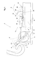
- Fig. 1 shows an actuator 2, which serves to act on at least one foot pedal 4 of a motor vehicle, such as in the course of an endurance test or for automated operation of the motor vehicle.
- the actuator device 2 has an actuating element 6 for each foot pedal 4 to be actuated, which by means of an actuator 8 between a Beaufschlagungswolf shown by solid lines and a dot-dash line Lines shown release position is reciprocable.
- the actuator device may alternatively or additionally have at least one actuating element 6, for example for actuating a brake pedal or accelerator pedal.
- actuating element 6 presses this with a pressure force D1 against the foot pedal 4 and holds it in this depressed position, which corresponds in the case of the clutch pedal a separate position of the respective clutch.
- a brake pedal corresponds to the depressed position of a brake position and in the case of an accelerator pedal a gas supply.
- the actuating element 6 is pivoted by the actuator 8 about an axis A into the release position shown in FIG. 6'.
- the starting position according to 4 'of the foot pedal 4 corresponds in the case of the clutch pedal a coupled position of the respective clutch. In the case of the brake pedal brake in question is released in this position and terminated in the case of the accelerator pedal of the power drive.
- the actuator 2 additionally comprises an emergency stop device 10, by means of which the foot pedal 4, as shown, can be acted upon via the actuating element 6.
- the Notausvoriques has for this purpose a spring means 12, which is formed by way of example by a gas spring. This presses on a side facing away from the foot pedal 4 against the actuating element 6 and biases it in such a way that it exerts sufficient pressure force D1 on the foot pedal 4 even without the assistance of the actuator 8, in order to shift it into the depressed position.
- the depressed position corresponds to an emergency exhibition of the foot pedal 4, which is to be taken in an emergency, such as failure of a control signal or a supply voltage, for example, in the case of the clutch pedal to disconnect the clutch or decelerate the vehicle in the case of the brake pedal.
- the actuator 8 In normal operation, the actuator 8 must thus generate sufficient torque to move the actuator 6 against the bias of the spring means 12 in the release position according to 6 '.
- the accelerator pedal corresponds to the emergency exhibition of the foot pedal 4 in contrast to the clutch or brake pedal the non-depressed position according to 4 '.
- a corresponding Notausvorraum 10 ' as shown by dotted line, at a respect to the axis A of the foot pedal 4 acting on parts of the actuating element 6 remote arm 14 attack.
- the actuating element 6 can be biased away from the foot pedal 4 by the pressurization of the alternative emergency stop device 10 '.
- the actuator 8 must overcome the bias of Notausvortechnisch 10 when the actuator 6 is to be moved from the release position according to 6 'in the illustrated Beaufschlagungswolf.
- the Notausvorraum 10 has a bearing device 16, on which the spring device 12 is held.
- This bearing device 16 has a base 18 on which a toggle lever 20 is held.
- the toggle lever 20 is connected to a first arm 22 with a carriage 24 on which the spring device 12 is held and which is displaceable along a guide 25 provided on the base 18.
- a second arm 26 of the toggle lever 20 is connected to a fixed bearing 28 and has a handle 30.
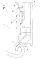
- the toggle lever 20 By actuating the handle 30 along the direction B, the toggle lever 20 from the first storage position to a second storage position according to Fig. 2 be spent, at the same time the carriage 24 is moved along the guide 25 in a position in which he has such a large distance relative to the actuating element 6, that this can no longer be acted upon by the spring means 12.
- the Notausvorraum 10 is thus in a passive position, in which no action on the foot pedal 4, such as brake or clutch pedal, by force of the Notausvorraum can be done.
- Notausvoriques 10 'according to Fig. 1 be spaced from the actuator 6 in order to disable them on an accelerator pedal can.
Landscapes
- Engineering & Computer Science (AREA)
- Physics & Mathematics (AREA)
- General Physics & Mathematics (AREA)
- Transportation (AREA)
- Mechanical Engineering (AREA)
- Automation & Control Theory (AREA)
- Mechanical Control Devices (AREA)
Abstract
Description
Die Erfindung betrifft eine Aktuatorvorrichtung zur Betätigung wenigstens eines Fußpedals, wie eines Brems-, Gas- oder Kupplungspedals, eines Kraftfahrzeugs nach dem Oberbegriff des Anspruchs 1. Die Aktuatorvorrichtung weist hierzu wenigstens ein Betätigungselement auf, das zur wiederkehrenden Beaufschlagung des Fußpedals mittels eines Stellantriebes zwischen einer Beaufschlagungsstellung und einer Freigabestellung verlagerbar ist. Zudem weist die Aktuatorvorrichtung eine Notausvorrichtung auf, mittels der das wenigstens eine Fußpedal in eine Notausstellung verlagerbar ist, in der es bei einem vordefinierten Notfall gehalten werden soll. Dabei ist die Notausvorrichtung an der Aktuatorvorrichtung zwischen einer Aktivstellung und einer Passivstellung verstellbar gelagert. Ein Notfall kann beispielsweise dadurch gegeben sein, dass während der Verwendung der Aktuatorvorrichtung die Versorgungsspannung abfällt oder vollständig ausfällt, so dass die Aktuatorvorrichtung nicht mehr oder nicht ausreichend genau steuerbar ist. Abhängig von der Art des betreffenden Fußpedals kann die Notausstellung dabei, wie beispielsweise bei einem Brems- oder Kupplungspedal durch die Beaufschlagungsstellung, oder wie im Falle eines Gaspedals durch die Freigabestellung gebildet sein.The invention relates to an actuator device for actuating at least one foot pedal, such as a brake, gas or clutch pedal, a motor vehicle according to the preamble of claim 1. The actuator has for this purpose at least one actuating element which is for recurring loading of the foot pedal by means of an actuator between a Beeaufschlagungsstellung and a release order is displaced. In addition, the actuator device has an emergency stop device by means of which the at least one foot pedal can be displaced into an emergency display, in which it is to be held in a predefined emergency. In this case, the Notausvorrichtung is adjustably mounted on the actuator between an active position and a passive position. An emergency can for example be given by the fact that during use of the actuator device, the supply voltage drops or fails completely, so that the actuator device is no longer or not sufficiently precisely controlled. Depending on the type of foot pedal concerned, the emergency exhibition may be formed by the admission position, as in the case of a brake or clutch pedal, or by the release position, as in the case of an accelerator pedal.
Derartige Aktuatorvorrichtungen werden benötigt, um beispielsweise Funktions- oder Dauertests der Fußpedale eines Kraftfahrzeuges, wie Gas-, Kupplungs- und Bremspedal durchzuführen oder das Fahrzeug automatisiert beziehungsweise teilautomatisiert zu fahren. Hierbei führt die Aktuatorvorrichtung wiederkehrende Bewegungsabläufe zur Beaufschlagung des wenigstens einen Fußpedals aus, die der tatsächlichen Betätigung der Fußpedale bei dem zu erwartenden Gebrauch des Fahrzeuges weitestgehend entsprechen.Such actuator devices are required, for example, to perform functional or endurance tests of the foot pedals of a motor vehicle, such as gas, clutch and brake pedals, or to drive the vehicle automatically or semi-automatically. In this case, the actuator device carries out recurrent sequences of motion for acting on the at least one foot pedal, which largely correspond to the actual actuation of the foot pedals in the expected use of the vehicle.
In
In der Regel werden derartige Aktuatorvorrichtungen nicht nur für einen bestimmten, sondern für verschiedene Tests verwendet. Je nach Art des Tests kann es dabei notwendig oder erwünscht sein, dass es während der Verwendung der Aktuatorvorrichtung zu keiner Betätigung des Fußpedals mittels der Notausvorrichtung kommen kann. In einem solchen Fall muss bei den bekannten Aktuatorvorrichtungen die Notausvorrichtung oder wenigstens Teile davon ausgebaut werden, was einen relativ hohen Zeitverlust und Arbeitsaufwand zwischen zwei Tests verursachen kann.As a rule, such actuator devices are used not only for a specific, but for various tests. Depending on the type of test, it may be necessary or desirable that during use of the actuator device, no operation of the foot pedal by means of the emergency stop device may occur. In such a case, in the known actuator devices, the emergency stop device or at least parts thereof must be removed, which can cause a relatively high loss of time and labor between tests.
Die Aufgabe der Erfindung ist es, bei einer gattungsgemäßen Aktuatorvorrichtung die genannten Nachteile zu vermeiden und einen einfachen Wechsel zwischen dem Betrieb der Aktuatorvorrichtung mit und ohne Notausfunktion zu ermöglichen.The object of the invention is to avoid the disadvantages mentioned in a generic actuator device and to enable a simple change between the operation of the actuator with and without emergency shutdown.
Diese Aufgabe wird durch eine Aktuatorvorrichtung mit den Merkmalen des Anspruchs 1 gelöst. In der Aktivstellung erzeugt die Notausvorrichtung dabei eine vom Stellantrieb überwindbare Vorspannung an dem Betätigungselement, durch die das Fußpedal auch ohne Unterstützung des Stellantriebes mittels der Notausvorrichtung in die Notausstellung verlagerbar ist, während in der Passivstellung eine Verlagerung des Fußpedals in die Notausstellung mittels der Notausvorrichtung unterbunden ist. Hierdurch kann die Aktuatorvorrichtung durch bloße Positionsverlagerung der Notausvorrichtung bedarfsweise mit oder ohne Notausfunktion betrieben werden. Umbaumaßnahmen an der Aktuatorvorrichtung sind hierbei nicht erforderlich.This object is achieved by an actuator device having the features of claim 1. In the active position, the Notausvorrichtung generates a surmountable by the actuator bias on the actuator through which the foot pedal is displaced without support of the actuator by means of Notausvorrichtung in the emergency exhibition, while in the passive position, a shift of the foot pedal is prevented in the emergency exhibition by means of Notausvorrichtung , As a result, the actuator device can be operated by simply shifting the position of the emergency stop device, if necessary, with or without emergency stop function. Conversion measures to the actuator device are not required here.
In einer besonders vorteilhaften Ausführungsform weist die Notausvorrichtung eine Federeinrichtung auf, die mittels einer Handhabe zwischen der Aktivstellung und der Passivstellung verlagerbar ist. Hierdurch ist die Notausfunktion der Aktuatorvorrichtung in besonders komfortabler Weise verlagerbar und dadurch zu- und abschaltbar.In a particularly advantageous embodiment, the Notausvorrichtung to a spring device which is displaceable by means of a handle between the active position and the passive position. As a result, the Notausfunktion the actuator is displaced in a particularly comfortable manner and thereby switched on and off.
Dabei ist es günstig, wenn die Federeinrichtung an einer verstellbaren Lagervorrichtung gehalten ist und in der Aktivstellung eine Vorspannung aufweist, die die Lagervorrichtung in eine erste Lagerposition drückt. Auf diese Weise wird sichergestellt, dass die Notausvorrichtung stabil in der Aktivstellung gehalten werden kann.It is advantageous if the spring device is held on an adjustable bearing device and in the active position has a bias that presses the bearing device in a first storage position. In this way it is ensured that the Notausvorrichtung can be kept stable in the active position.
Vorteilhafterweise ist die Lagervorrichtung durch einen mittels der Handhabe verstellbaren Kniehebel gebildet, wodurch die veränderbare Lagerung der Notausvorrichtung mit relativ einfachen und dadurch kostengünstigen konstruktiven Maßnahmen erzielt werden kann.Advantageously, the storage device is formed by an adjustable by means of the handle knee lever, whereby the variable mounting of Notausvorrichtung can be achieved with relatively simple and therefore cost-effective design measures.
Zudem ist es günstig, wenn die Lagervorrichtung einen zwischen der Aktivstellung und der Passivstellung verschiebbaren Schlitten aufweist, an dem die Federeinrichtung gehalten ist. Hierdurch wird eine besonders stabile verschiebbare Lagerung der Notausvorrichtung ermöglicht.Moreover, it is favorable if the bearing device has a slide which can be displaced between the active position and the passive position and to which the spring device is held. As a result, a particularly stable displaceable mounting of Notausvorrichtung is possible.
Vorteilhafterweise weist die Federeinrichtung eine Gasdruckfeder auf, wodurch trotz relativ geringem Platzbedarf seitens der Federeinrichtung relativ große Stellkräfte auf das betreffende Betätigungselement oder direkt auf das betreffende Pedal abgegeben werden können, um dieses in die Notausstellung zu verbringen.Advantageously, the spring device on a gas spring, whereby despite relatively small space requirement by the spring means relatively large actuating forces can be delivered to the relevant actuator or directly to the relevant pedal to spend this in the emergency exhibition.
Ferner ist es günstig, wenn das Betätigungselement durch die Notausvorrichtung in die Beaufschlagungsstellung vorgespannt ist. Hierdurch kann beispielsweise ein Brems- oder Kupplungspedal, an dem das betreffende Betätigungselement ausgefallen ist, direkt oder unter Zwischenlage des Betätigungselementes in die Beaufschlagungsstellung verbracht werden, die der Notausstellung entspricht.Further, it is advantageous if the actuating element is biased by the Notausvorrichtung in the Beaufschlagungsstellung. As a result, for example, a brake or clutch pedal on which the relevant actuator has failed to be spent directly or with the interposition of the actuating element in the Beaufschlagungsstellung that corresponds to the emergency exhibition.
Alternativ hierzu ist es günstig, wenn das Betätigungselement durch die Notausvorrichtung in die Freigabestellung vorgespannt ist. Hierdurch kann beispielsweise ein Gaspedal, an dem das betreffende Betätigungselement ausgefallen ist, direkt oder unter Zwischenlage des Betätigungselementes in die Freigabestellung verbracht werden, die in diesem Fall der Notausstellung entspricht.Alternatively, it is advantageous if the actuating element is biased by the Notausvorrichtung in the release position. As a result, for example, an accelerator pedal on which the relevant actuating element has failed, be brought directly or with the interposition of the actuating element in the release position, which corresponds to the emergency exhibition in this case.
In den Figuren ist eine beispielhafte Ausführungsform der Erfindung dargestellt. Es zeigen:
- Figur 1
- eine Ansicht einer erfindungsgemäßen Aktuatorvorrichtung mit einer Notausvorrichtung in Aktivstellung und
Figur 2- eine Ansicht der Aktuatorvorrichtung mit der Notausvorrichtung in Passivstellung.
- FIG. 1
- a view of an actuator according to the invention with a Notausvorrichtung in the active position and
- FIG. 2
- a view of the actuator with the Notausvorrichtung in passive position.
In der in
Soll sich das Fußpedal 4 dagegen in eine unbetätigte Ausgangsstellung gemäß 4' zurück verstellen können, so wird das Betätigungselement 6 durch den Stellantrieb 8 um eine Achse A herum in die durch strichpunktierte Linien dargestellte Freigabestellung gemäß 6' verschwenkt. Die Ausgangsstellung gemäß 4' des Fußpedals 4 entspricht dabei im Falle des Kupplungspedals einer gekuppelten Stellung der betreffenden Kupplung. Im Falle des Bremspedals wird die betreffende Bremse in dieser Stellung freigegeben und im Falle des Gaspedals der Kraftantrieb beendet.If, on the other hand, the
Wie aus
Die gedrückte Stellung entspricht dabei einer Notausstellung des Fußpedals 4, die in einem Notfall, wie beispielsweise bei Ausfall eines Steuerungssignals oder einer Versorgungsspannung, eingenommen werden soll, um beispielsweise im Falle des Kupplungspedals die Kupplung zu trennen oder im Falle des Bremspedals das Fahrzeug abzubremsen.The depressed position corresponds to an emergency exhibition of the
Im normalen Betrieb muss der Stellantrieb 8 somit ein ausreichendes Drehmoment erzeugen, um das Betätigungselement 6 entgegen der Vorspannung durch die Federeinrichtung 12 in die Freigabestellung gemäß 6' zu verlagern.In normal operation, the
Im Falle des Gaspedals entspricht die Notausstellung des Fußpedals 4 im Gegensatz zum Kupplungs- oder Bremspedal der nicht gedrückten Stellung gemäß 4'. Um im Notfall auch diese Notausstellung des Fußpedals 4 gewährleisten zu können, kann eine entsprechende Notausvorrichtung 10', wie durch strichpunktierte Linie dargestellt, an einem bezüglich der Achse A von dem das Fußpedal 4 beaufschlagenden Teile des Betätigungselementes 6 abgewandten Arm 14 angreifen. Hierdurch kann das Betätigungselement 6 durch die Druckbeaufschlagung der alternativen Notausvorrichtung 10' von dem Fußpedal 4 weg vorgespannt werden. In diesem Fall muss der Stellantrieb 8 die Vorspannung der Notausvorrichtung 10 überwinden, wenn das Betätigungselement 6 von der Freigabestellung gemäß 6' in die dargestellte Beaufschlagungsstellung verbracht werden soll.In the case of the accelerator pedal corresponds to the emergency exhibition of the
Wie aus
In der in
Mittels Betätigung der Handhabe 30 entlang Richtung B kann der Kniehebel 20 aus der ersten Lagerposition in eine zweite Lagerposition gemäß
In gleicher Weise kann auch eine auf den abgewandten Arm 14 einwirkende Notausvorrichtung 10' gemäß
Claims (8)
mit wenigstens einem Betätigungselement (6), das zur Beaufschlagung des Fußpedals (4) mittels eines Stellantriebes (8) zwischen einer Beaufschlagungsstellung und einer Freigabestellung verlagerbar ist und
mit einer Notausvorrichtung (10) mittels der das Fußpedal (4) in eine Notausstellung verbringbar ist,
wobei die Notausvorrichtung (10) an der Aktuatorvorrichtung (2) zwischen einer Aktivstellung und einer Passivstellung verstellbar gelagert ist,
dadurch gekennzeichnet, dass die Notausvorrichtung (10) in der Aktivstellung eine vom Stellantrieb (8) überwindbare Vorspannung an dem Betätigungselement (6) erzeugt, durch die das Fußpedal (4) mittels der Notausvorrichtung (10) in die Notausstellung verlagerbar ist,
und in der Passivstellung eine Verlagerung des Fußpedals (4) in die Notausstellung mittels der Notausvorrichtung (10) unterbunden ist.Actuator device (2) for actuating at least one foot pedal (4) of a motor vehicle
with at least one actuating element (6), which is displaceable to act on the foot pedal (4) by means of an actuator (8) between a Beaufschlagungsstellung and a release position, and
with an emergency stop device (10) by means of which the foot pedal (4) can be brought into an emergency exhibition,
wherein the emergency stop device (10) is adjustably mounted on the actuator device (2) between an active position and a passive position,
characterized in that the Notausvorrichtung (10) generated in the active position by the actuator (8) surmountable bias on the actuating element (6) through which the foot pedal (4) by means of the Notausvorrichtung (10) is displaced into the emergency exhibition,
and in the passive position, a displacement of the foot pedal (4) is prevented in the emergency exhibition by the Notausvorrichtung (10).
Applications Claiming Priority (1)
| Application Number | Priority Date | Filing Date | Title |
|---|---|---|---|
| DE201010045786 DE102010045786B4 (en) | 2010-09-17 | 2010-09-17 | Actuator device with emergency stop function |
Publications (2)
| Publication Number | Publication Date |
|---|---|
| EP2431241A1 true EP2431241A1 (en) | 2012-03-21 |
| EP2431241B1 EP2431241B1 (en) | 2013-05-01 |
Family
ID=44582008
Family Applications (1)
| Application Number | Title | Priority Date | Filing Date |
|---|---|---|---|
| EP20110007342 Not-in-force EP2431241B1 (en) | 2010-09-17 | 2011-09-09 | Actuator device with emergency stop function |
Country Status (2)
| Country | Link |
|---|---|
| EP (1) | EP2431241B1 (en) |
| DE (1) | DE102010045786B4 (en) |
Cited By (7)
| Publication number | Priority date | Publication date | Assignee | Title |
|---|---|---|---|---|
| CN104236894A (en) * | 2014-10-11 | 2014-12-24 | 安徽合力股份有限公司 | Vehicle-mounted test device for detecting reliability of forklift pedal mechanism |
| CN104340189A (en) * | 2013-08-04 | 2015-02-11 | 金亚静 | Remote-control auxiliary brake for car |
| CN105738124A (en) * | 2014-02-13 | 2016-07-06 | 重庆建设摩托车股份有限公司 | Motorcycle recoil starting lever assembly pedaling rod rotation endurance test device and test method |
| EP3199413A1 (en) | 2016-01-27 | 2017-08-02 | Kurt Stähle | Actuator device |
| CN112595522A (en) * | 2020-11-11 | 2021-04-02 | 中汽研汽车检验中心(天津)有限公司 | Accelerator test auxiliary device |
| CN112857818A (en) * | 2019-11-12 | 2021-05-28 | 广州汽车集团股份有限公司 | Accelerator pedal control device and method |
| CN112951029A (en) * | 2021-01-22 | 2021-06-11 | 武汉木仓科技股份有限公司 | Pedal operation detection device of driving training robot and vehicle |
Families Citing this family (1)
| Publication number | Priority date | Publication date | Assignee | Title |
|---|---|---|---|---|
| CN109596362A (en) * | 2018-12-08 | 2019-04-09 | 哈尔滨东安汽车动力股份有限公司 | A kind of novel analog vehicle gear shift operating condition noise test mechanism |
Citations (7)
| Publication number | Priority date | Publication date | Assignee | Title |
|---|---|---|---|---|
| US3662593A (en) * | 1970-11-23 | 1972-05-16 | Gen Motors Corp | Test apparatus for depressing vehicle brake and accelerator pedals |
| FR2507556A1 (en) * | 1981-06-11 | 1982-12-17 | Garcia Andre | Radio controlled brake actuator for driving tuition car - uses double acting hydraulic cylinder connected to brake pedal to stop vehicle in response to remote radio signal |
| EP0236518A1 (en) | 1986-03-08 | 1987-09-16 | Carl Schenck Ag | Apparatus and process for the automatic operation of operating devices of motor vehicles |
| DE4240756A1 (en) | 1991-12-07 | 1993-06-09 | Horiba Ltd., Kyoto, Jp | Robot for operating motor vehicle on chassis dynamometer - controls robotic body by placing operating device in safety position when hardware or software fault occurs |
| US5821718A (en) * | 1996-05-07 | 1998-10-13 | Chrysler Corporation | Robotic system for automated durability road (ADR) facility |
| DE10012757A1 (en) | 2000-03-16 | 2001-09-20 | Volkswagen Ag | Safeguarding device for actuator of setting device, has clamping unit with contact surface loaded on the operational organ through the actuator of setting device |
| FR2893550A3 (en) * | 2005-11-24 | 2007-05-25 | Renault Sas | Accelerator pedal actuator for motor vehicle, has support element for forming physical support on accelerator pedal, where actuator is associated to automatic fire detection system and emergency stop |
-
2010
- 2010-09-17 DE DE201010045786 patent/DE102010045786B4/en not_active Expired - Fee Related
-
2011
- 2011-09-09 EP EP20110007342 patent/EP2431241B1/en not_active Not-in-force
Patent Citations (7)
| Publication number | Priority date | Publication date | Assignee | Title |
|---|---|---|---|---|
| US3662593A (en) * | 1970-11-23 | 1972-05-16 | Gen Motors Corp | Test apparatus for depressing vehicle brake and accelerator pedals |
| FR2507556A1 (en) * | 1981-06-11 | 1982-12-17 | Garcia Andre | Radio controlled brake actuator for driving tuition car - uses double acting hydraulic cylinder connected to brake pedal to stop vehicle in response to remote radio signal |
| EP0236518A1 (en) | 1986-03-08 | 1987-09-16 | Carl Schenck Ag | Apparatus and process for the automatic operation of operating devices of motor vehicles |
| DE4240756A1 (en) | 1991-12-07 | 1993-06-09 | Horiba Ltd., Kyoto, Jp | Robot for operating motor vehicle on chassis dynamometer - controls robotic body by placing operating device in safety position when hardware or software fault occurs |
| US5821718A (en) * | 1996-05-07 | 1998-10-13 | Chrysler Corporation | Robotic system for automated durability road (ADR) facility |
| DE10012757A1 (en) | 2000-03-16 | 2001-09-20 | Volkswagen Ag | Safeguarding device for actuator of setting device, has clamping unit with contact surface loaded on the operational organ through the actuator of setting device |
| FR2893550A3 (en) * | 2005-11-24 | 2007-05-25 | Renault Sas | Accelerator pedal actuator for motor vehicle, has support element for forming physical support on accelerator pedal, where actuator is associated to automatic fire detection system and emergency stop |
Cited By (11)
| Publication number | Priority date | Publication date | Assignee | Title |
|---|---|---|---|---|
| CN104340189A (en) * | 2013-08-04 | 2015-02-11 | 金亚静 | Remote-control auxiliary brake for car |
| CN105738124A (en) * | 2014-02-13 | 2016-07-06 | 重庆建设摩托车股份有限公司 | Motorcycle recoil starting lever assembly pedaling rod rotation endurance test device and test method |
| CN104236894A (en) * | 2014-10-11 | 2014-12-24 | 安徽合力股份有限公司 | Vehicle-mounted test device for detecting reliability of forklift pedal mechanism |
| EP3199413A1 (en) | 2016-01-27 | 2017-08-02 | Kurt Stähle | Actuator device |
| US10401894B2 (en) | 2016-01-27 | 2019-09-03 | Kurt Staehle | Actuator device |
| CN112857818A (en) * | 2019-11-12 | 2021-05-28 | 广州汽车集团股份有限公司 | Accelerator pedal control device and method |
| CN112857818B (en) * | 2019-11-12 | 2023-05-30 | 广州汽车集团股份有限公司 | Accelerator pedal control device and method |
| CN112595522A (en) * | 2020-11-11 | 2021-04-02 | 中汽研汽车检验中心(天津)有限公司 | Accelerator test auxiliary device |
| CN112595522B (en) * | 2020-11-11 | 2022-11-01 | 中汽研汽车检验中心(天津)有限公司 | Accelerator test auxiliary device |
| CN112951029A (en) * | 2021-01-22 | 2021-06-11 | 武汉木仓科技股份有限公司 | Pedal operation detection device of driving training robot and vehicle |
| CN112951029B (en) * | 2021-01-22 | 2023-05-05 | 武汉木仓科技股份有限公司 | Pedal operation detection device of driving training robot and vehicle |
Also Published As
| Publication number | Publication date |
|---|---|
| DE102010045786B4 (en) | 2013-03-14 |
| EP2431241B1 (en) | 2013-05-01 |
| DE102010045786A1 (en) | 2012-03-22 |
Similar Documents
| Publication | Publication Date | Title |
|---|---|---|
| EP2431241B1 (en) | Actuator device with emergency stop function | |
| EP3213168B1 (en) | Device for simulating a force on an actuation element of a vehicle, preferably a pedal simulator | |
| DE102010037955A1 (en) | Electronic switching device for a vehicle | |
| DE102019101646A1 (en) | Pedal emulator for a vehicle | |
| DE102008015874A1 (en) | Actuator with haptic emulation | |
| EP1997700A2 (en) | Actuation device for a braking system | |
| DE102011052504B4 (en) | Accelerator pedal for vehicle | |
| DE102010026956A1 (en) | pedal arrangement | |
| EP1531100B1 (en) | Electric parking brake actuator for vehicle | |
| EP1646575B1 (en) | Cable brake | |
| DE202015106673U1 (en) | Bayable component | |
| DE102012207940A1 (en) | INTERCHANGEABLE STEERING COLUMN WITH TILTING SPRING | |
| EP2359984A1 (en) | Stepping gear for a tensioning and/or spreading tool and tensioning and/or spreading tool | |
| DE102007058110B4 (en) | switch | |
| WO2017137033A2 (en) | Hysteresis element for generating a defined friction force and apparatus for simulating a force applied to an operating element of a vehicle | |
| DE102010029199A1 (en) | Acceleration pedal for motor vehicle, has controllable electromagnetic actuator cooperating with return spring, such that restoring force of acceleration pedal is altered, where position of pedal is changed by corresponding operating force | |
| WO2015165449A1 (en) | Device for simulating a force on an actuation element of a vehicle, preferably a pedal simulator | |
| DE102022107979A1 (en) | Switch control arrangement | |
| WO2005075852A2 (en) | Actuator, especially for a chassis | |
| DE102011106051A1 (en) | Control element e.g. push-button, has plunger driven by actuator and impressing movement during contacting control surface, and force-transferring bistable element arranged between plunger and control surface | |
| DE102019007170A1 (en) | Accelerator pedal unit | |
| DE102008054626A1 (en) | Driving pedal module for controlling engine performance of motor vehicle, has pedal element supported over pre-determined angle range tilted at clevis mounting | |
| DE102014005012B4 (en) | System for a pedal | |
| EP3301068A1 (en) | Industrial truck with an operating lever and a method of operating such an industrial truck | |
| EP2353949A2 (en) | Activation device for a parking brake |
Legal Events
| Date | Code | Title | Description |
|---|---|---|---|
| PUAI | Public reference made under article 153(3) epc to a published international application that has entered the european phase |
Free format text: ORIGINAL CODE: 0009012 |
|
| AK | Designated contracting states |
Kind code of ref document: A1 Designated state(s): AL AT BE BG CH CY CZ DE DK EE ES FI FR GB GR HR HU IE IS IT LI LT LU LV MC MK MT NL NO PL PT RO RS SE SI SK SM TR |
|
| AX | Request for extension of the european patent |
Extension state: BA ME |
|
| 17P | Request for examination filed |
Effective date: 20120921 |
|
| RIC1 | Information provided on ipc code assigned before grant |
Ipc: G05G 1/487 20080401ALI20121004BHEP Ipc: B60T 7/06 20060101ALI20121004BHEP Ipc: G01M 17/007 20060101ALI20121004BHEP Ipc: B60T 7/12 20060101ALI20121004BHEP Ipc: B60T 17/22 20060101ALI20121004BHEP Ipc: G05G 1/54 20080401ALI20121004BHEP Ipc: B60T 7/04 20060101ALI20121004BHEP Ipc: B60T 7/02 20060101AFI20121004BHEP Ipc: G01M 13/02 20060101ALI20121004BHEP Ipc: B60T 7/16 20060101ALI20121004BHEP |
|
| GRAP | Despatch of communication of intention to grant a patent |
Free format text: ORIGINAL CODE: EPIDOSNIGR1 |
|
| GRAS | Grant fee paid |
Free format text: ORIGINAL CODE: EPIDOSNIGR3 |
|
| GRAA | (expected) grant |
Free format text: ORIGINAL CODE: 0009210 |
|
| AK | Designated contracting states |
Kind code of ref document: B1 Designated state(s): AL AT BE BG CH CY CZ DE DK EE ES FI FR GB GR HR HU IE IS IT LI LT LU LV MC MK MT NL NO PL PT RO RS SE SI SK SM TR |
|
| REG | Reference to a national code |
Ref country code: GB Ref legal event code: FG4D Free format text: NOT ENGLISH |
|
| REG | Reference to a national code |
Ref country code: AT Ref legal event code: REF Ref document number: 609711 Country of ref document: AT Kind code of ref document: T Effective date: 20130515 Ref country code: CH Ref legal event code: EP |
|
| REG | Reference to a national code |
Ref country code: IE Ref legal event code: FG4D Free format text: LANGUAGE OF EP DOCUMENT: GERMAN |
|
| REG | Reference to a national code |
Ref country code: DE Ref legal event code: R096 Ref document number: 502011000670 Country of ref document: DE Effective date: 20130627 |
|
| REG | Reference to a national code |
Ref country code: NL Ref legal event code: VDEP Effective date: 20130501 |
|
| REG | Reference to a national code |
Ref country code: LT Ref legal event code: MG4D |
|
| PG25 | Lapsed in a contracting state [announced via postgrant information from national office to epo] |
Ref country code: FI Free format text: LAPSE BECAUSE OF FAILURE TO SUBMIT A TRANSLATION OF THE DESCRIPTION OR TO PAY THE FEE WITHIN THE PRESCRIBED TIME-LIMIT Effective date: 20130501 Ref country code: GR Free format text: LAPSE BECAUSE OF FAILURE TO SUBMIT A TRANSLATION OF THE DESCRIPTION OR TO PAY THE FEE WITHIN THE PRESCRIBED TIME-LIMIT Effective date: 20130802 Ref country code: SE Free format text: LAPSE BECAUSE OF FAILURE TO SUBMIT A TRANSLATION OF THE DESCRIPTION OR TO PAY THE FEE WITHIN THE PRESCRIBED TIME-LIMIT Effective date: 20130501 Ref country code: PT Free format text: LAPSE BECAUSE OF FAILURE TO SUBMIT A TRANSLATION OF THE DESCRIPTION OR TO PAY THE FEE WITHIN THE PRESCRIBED TIME-LIMIT Effective date: 20130902 Ref country code: SI Free format text: LAPSE BECAUSE OF FAILURE TO SUBMIT A TRANSLATION OF THE DESCRIPTION OR TO PAY THE FEE WITHIN THE PRESCRIBED TIME-LIMIT Effective date: 20130501 Ref country code: LT Free format text: LAPSE BECAUSE OF FAILURE TO SUBMIT A TRANSLATION OF THE DESCRIPTION OR TO PAY THE FEE WITHIN THE PRESCRIBED TIME-LIMIT Effective date: 20130501 Ref country code: ES Free format text: LAPSE BECAUSE OF FAILURE TO SUBMIT A TRANSLATION OF THE DESCRIPTION OR TO PAY THE FEE WITHIN THE PRESCRIBED TIME-LIMIT Effective date: 20130812 Ref country code: IS Free format text: LAPSE BECAUSE OF FAILURE TO SUBMIT A TRANSLATION OF THE DESCRIPTION OR TO PAY THE FEE WITHIN THE PRESCRIBED TIME-LIMIT Effective date: 20130901 Ref country code: NO Free format text: LAPSE BECAUSE OF FAILURE TO SUBMIT A TRANSLATION OF THE DESCRIPTION OR TO PAY THE FEE WITHIN THE PRESCRIBED TIME-LIMIT Effective date: 20130801 |
|
| PG25 | Lapsed in a contracting state [announced via postgrant information from national office to epo] |
Ref country code: CY Free format text: LAPSE BECAUSE OF FAILURE TO SUBMIT A TRANSLATION OF THE DESCRIPTION OR TO PAY THE FEE WITHIN THE PRESCRIBED TIME-LIMIT Effective date: 20130501 Ref country code: HR Free format text: LAPSE BECAUSE OF FAILURE TO SUBMIT A TRANSLATION OF THE DESCRIPTION OR TO PAY THE FEE WITHIN THE PRESCRIBED TIME-LIMIT Effective date: 20130501 Ref country code: BG Free format text: LAPSE BECAUSE OF FAILURE TO SUBMIT A TRANSLATION OF THE DESCRIPTION OR TO PAY THE FEE WITHIN THE PRESCRIBED TIME-LIMIT Effective date: 20130801 Ref country code: RS Free format text: LAPSE BECAUSE OF FAILURE TO SUBMIT A TRANSLATION OF THE DESCRIPTION OR TO PAY THE FEE WITHIN THE PRESCRIBED TIME-LIMIT Effective date: 20130501 Ref country code: PL Free format text: LAPSE BECAUSE OF FAILURE TO SUBMIT A TRANSLATION OF THE DESCRIPTION OR TO PAY THE FEE WITHIN THE PRESCRIBED TIME-LIMIT Effective date: 20130501 |
|
| PG25 | Lapsed in a contracting state [announced via postgrant information from national office to epo] |
Ref country code: LV Free format text: LAPSE BECAUSE OF FAILURE TO SUBMIT A TRANSLATION OF THE DESCRIPTION OR TO PAY THE FEE WITHIN THE PRESCRIBED TIME-LIMIT Effective date: 20130501 |
|
| PG25 | Lapsed in a contracting state [announced via postgrant information from national office to epo] |
Ref country code: CZ Free format text: LAPSE BECAUSE OF FAILURE TO SUBMIT A TRANSLATION OF THE DESCRIPTION OR TO PAY THE FEE WITHIN THE PRESCRIBED TIME-LIMIT Effective date: 20130501 Ref country code: DK Free format text: LAPSE BECAUSE OF FAILURE TO SUBMIT A TRANSLATION OF THE DESCRIPTION OR TO PAY THE FEE WITHIN THE PRESCRIBED TIME-LIMIT Effective date: 20130501 Ref country code: SK Free format text: LAPSE BECAUSE OF FAILURE TO SUBMIT A TRANSLATION OF THE DESCRIPTION OR TO PAY THE FEE WITHIN THE PRESCRIBED TIME-LIMIT Effective date: 20130501 Ref country code: EE Free format text: LAPSE BECAUSE OF FAILURE TO SUBMIT A TRANSLATION OF THE DESCRIPTION OR TO PAY THE FEE WITHIN THE PRESCRIBED TIME-LIMIT Effective date: 20130501 |
|
| PG25 | Lapsed in a contracting state [announced via postgrant information from national office to epo] |
Ref country code: NL Free format text: LAPSE BECAUSE OF FAILURE TO SUBMIT A TRANSLATION OF THE DESCRIPTION OR TO PAY THE FEE WITHIN THE PRESCRIBED TIME-LIMIT Effective date: 20130501 Ref country code: RO Free format text: LAPSE BECAUSE OF FAILURE TO SUBMIT A TRANSLATION OF THE DESCRIPTION OR TO PAY THE FEE WITHIN THE PRESCRIBED TIME-LIMIT Effective date: 20130501 Ref country code: IT Free format text: LAPSE BECAUSE OF FAILURE TO SUBMIT A TRANSLATION OF THE DESCRIPTION OR TO PAY THE FEE WITHIN THE PRESCRIBED TIME-LIMIT Effective date: 20130501 |
|
| PLBE | No opposition filed within time limit |
Free format text: ORIGINAL CODE: 0009261 |
|
| STAA | Information on the status of an ep patent application or granted ep patent |
Free format text: STATUS: NO OPPOSITION FILED WITHIN TIME LIMIT |
|
| BERE | Be: lapsed |
Owner name: STAHLE, KURT Effective date: 20130930 |
|
| 26N | No opposition filed |
Effective date: 20140204 |
|
| PG25 | Lapsed in a contracting state [announced via postgrant information from national office to epo] |
Ref country code: MC Free format text: LAPSE BECAUSE OF FAILURE TO SUBMIT A TRANSLATION OF THE DESCRIPTION OR TO PAY THE FEE WITHIN THE PRESCRIBED TIME-LIMIT Effective date: 20130501 |
|
| REG | Reference to a national code |
Ref country code: DE Ref legal event code: R097 Ref document number: 502011000670 Country of ref document: DE Effective date: 20140204 |
|
| REG | Reference to a national code |
Ref country code: FR Ref legal event code: ST Effective date: 20140530 |
|
| REG | Reference to a national code |
Ref country code: IE Ref legal event code: MM4A |
|
| PG25 | Lapsed in a contracting state [announced via postgrant information from national office to epo] |
Ref country code: BE Free format text: LAPSE BECAUSE OF NON-PAYMENT OF DUE FEES Effective date: 20130930 Ref country code: IE Free format text: LAPSE BECAUSE OF NON-PAYMENT OF DUE FEES Effective date: 20130909 |
|
| PG25 | Lapsed in a contracting state [announced via postgrant information from national office to epo] |
Ref country code: FR Free format text: LAPSE BECAUSE OF NON-PAYMENT OF DUE FEES Effective date: 20130930 |
|
| REG | Reference to a national code |
Ref country code: CH Ref legal event code: PL |
|
| PG25 | Lapsed in a contracting state [announced via postgrant information from national office to epo] |
Ref country code: SM Free format text: LAPSE BECAUSE OF FAILURE TO SUBMIT A TRANSLATION OF THE DESCRIPTION OR TO PAY THE FEE WITHIN THE PRESCRIBED TIME-LIMIT Effective date: 20130501 |
|
| PG25 | Lapsed in a contracting state [announced via postgrant information from national office to epo] |
Ref country code: TR Free format text: LAPSE BECAUSE OF FAILURE TO SUBMIT A TRANSLATION OF THE DESCRIPTION OR TO PAY THE FEE WITHIN THE PRESCRIBED TIME-LIMIT Effective date: 20130501 Ref country code: MT Free format text: LAPSE BECAUSE OF FAILURE TO SUBMIT A TRANSLATION OF THE DESCRIPTION OR TO PAY THE FEE WITHIN THE PRESCRIBED TIME-LIMIT Effective date: 20130501 |
|
| PG25 | Lapsed in a contracting state [announced via postgrant information from national office to epo] |
Ref country code: CH Free format text: LAPSE BECAUSE OF NON-PAYMENT OF DUE FEES Effective date: 20140930 Ref country code: HU Free format text: LAPSE BECAUSE OF FAILURE TO SUBMIT A TRANSLATION OF THE DESCRIPTION OR TO PAY THE FEE WITHIN THE PRESCRIBED TIME-LIMIT; INVALID AB INITIO Effective date: 20110909 Ref country code: LI Free format text: LAPSE BECAUSE OF NON-PAYMENT OF DUE FEES Effective date: 20140930 Ref country code: MK Free format text: LAPSE BECAUSE OF FAILURE TO SUBMIT A TRANSLATION OF THE DESCRIPTION OR TO PAY THE FEE WITHIN THE PRESCRIBED TIME-LIMIT Effective date: 20130501 Ref country code: LU Free format text: LAPSE BECAUSE OF NON-PAYMENT OF DUE FEES Effective date: 20130909 |
|
| GBPC | Gb: european patent ceased through non-payment of renewal fee |
Effective date: 20150909 |
|
| PG25 | Lapsed in a contracting state [announced via postgrant information from national office to epo] |
Ref country code: GB Free format text: LAPSE BECAUSE OF NON-PAYMENT OF DUE FEES Effective date: 20150909 |
|
| PGFP | Annual fee paid to national office [announced via postgrant information from national office to epo] |
Ref country code: DE Payment date: 20160709 Year of fee payment: 6 |
|
| REG | Reference to a national code |
Ref country code: AT Ref legal event code: MM01 Ref document number: 609711 Country of ref document: AT Kind code of ref document: T Effective date: 20160909 |
|
| PG25 | Lapsed in a contracting state [announced via postgrant information from national office to epo] |
Ref country code: AT Free format text: LAPSE BECAUSE OF NON-PAYMENT OF DUE FEES Effective date: 20160909 |
|
| REG | Reference to a national code |
Ref country code: DE Ref legal event code: R119 Ref document number: 502011000670 Country of ref document: DE |
|
| PG25 | Lapsed in a contracting state [announced via postgrant information from national office to epo] |
Ref country code: DE Free format text: LAPSE BECAUSE OF NON-PAYMENT OF DUE FEES Effective date: 20180404 |
|
| PG25 | Lapsed in a contracting state [announced via postgrant information from national office to epo] |
Ref country code: AL Free format text: LAPSE BECAUSE OF FAILURE TO SUBMIT A TRANSLATION OF THE DESCRIPTION OR TO PAY THE FEE WITHIN THE PRESCRIBED TIME-LIMIT Effective date: 20130501 |
|
| RIC2 | Information provided on ipc code assigned after grant |
Ipc: G05G 1/487 20080401ALI20121004BHEP Ipc: G05G 1/54 20080401ALI20121004BHEP Ipc: B60T 7/06 20060101ALI20121004BHEP Ipc: B60T 7/16 20060101ALI20121004BHEP Ipc: B60T 17/22 20060101ALI20121004BHEP Ipc: B60T 7/12 20060101ALI20121004BHEP Ipc: G01M 17/007 20060101ALI20121004BHEP Ipc: G01M 13/02 20190101ALI20121004BHEP Ipc: B60T 7/04 20060101ALI20121004BHEP Ipc: B60T 7/02 20060101AFI20121004BHEP |