EP2431058B1 - Aseptic sterilisation unit for clean room - Google Patents
Aseptic sterilisation unit for clean room Download PDFInfo
- Publication number
- EP2431058B1 EP2431058B1 EP11181565.0A EP11181565A EP2431058B1 EP 2431058 B1 EP2431058 B1 EP 2431058B1 EP 11181565 A EP11181565 A EP 11181565A EP 2431058 B1 EP2431058 B1 EP 2431058B1
- Authority
- EP
- European Patent Office
- Prior art keywords
- isolator
- room
- supplying
- isolator room
- sterilization agent
- Prior art date
- Legal status (The legal status is an assumption and is not a legal conclusion. Google has not performed a legal analysis and makes no representation as to the accuracy of the status listed.)
- Active
Links
- 238000004659 sterilization and disinfection Methods 0.000 title claims description 41
- 239000003206 sterilizing agent Substances 0.000 claims description 86
- 230000001954 sterilising effect Effects 0.000 claims description 44
- 239000004033 plastic Substances 0.000 claims description 41
- 229920003023 plastic Polymers 0.000 claims description 41
- 239000003795 chemical substances by application Substances 0.000 claims description 26
- 238000007664 blowing Methods 0.000 claims description 22
- 238000000071 blow moulding Methods 0.000 claims description 20
- 238000000034 method Methods 0.000 claims description 9
- 239000012212 insulator Substances 0.000 claims description 6
- 239000007788 liquid Substances 0.000 claims description 5
- 238000004140 cleaning Methods 0.000 claims description 3
- 238000011109 contamination Methods 0.000 claims description 3
- 238000002347 injection Methods 0.000 claims description 2
- 239000007924 injection Substances 0.000 claims description 2
- 239000000463 material Substances 0.000 claims 3
- 230000035515 penetration Effects 0.000 claims 1
- 230000032258 transport Effects 0.000 description 8
- 239000000443 aerosol Substances 0.000 description 7
- 239000007789 gas Substances 0.000 description 6
- 239000000243 solution Substances 0.000 description 5
- MHAJPDPJQMAIIY-UHFFFAOYSA-N Hydrogen peroxide Chemical compound OO MHAJPDPJQMAIIY-UHFFFAOYSA-N 0.000 description 4
- KFSLWBXXFJQRDL-UHFFFAOYSA-N Peracetic acid Chemical compound CC(=O)OO KFSLWBXXFJQRDL-UHFFFAOYSA-N 0.000 description 4
- 230000036512 infertility Effects 0.000 description 4
- 239000003595 mist Substances 0.000 description 4
- 230000005855 radiation Effects 0.000 description 4
- 239000000645 desinfectant Substances 0.000 description 3
- 238000009826 distribution Methods 0.000 description 3
- 239000000126 substance Substances 0.000 description 3
- 230000000844 anti-bacterial effect Effects 0.000 description 2
- 238000000889 atomisation Methods 0.000 description 2
- 244000052616 bacterial pathogen Species 0.000 description 2
- 238000005429 filling process Methods 0.000 description 2
- 230000000855 fungicidal effect Effects 0.000 description 2
- 238000010438 heat treatment Methods 0.000 description 2
- 238000007789 sealing Methods 0.000 description 2
- 230000003330 sporicidal effect Effects 0.000 description 2
- 230000003253 viricidal effect Effects 0.000 description 2
- 238000005406 washing Methods 0.000 description 2
- XLYOFNOQVPJJNP-UHFFFAOYSA-N water Substances O XLYOFNOQVPJJNP-UHFFFAOYSA-N 0.000 description 2
- CBENFWSGALASAD-UHFFFAOYSA-N Ozone Chemical compound [O-][O+]=O CBENFWSGALASAD-UHFFFAOYSA-N 0.000 description 1
- 238000005299 abrasion Methods 0.000 description 1
- 150000001298 alcohols Chemical class 0.000 description 1
- 239000007864 aqueous solution Substances 0.000 description 1
- 230000004888 barrier function Effects 0.000 description 1
- 238000001035 drying Methods 0.000 description 1
- 230000009969 flowable effect Effects 0.000 description 1
- QWPPOHNGKGFGJK-UHFFFAOYSA-N hypochlorous acid Chemical compound ClO QWPPOHNGKGFGJK-UHFFFAOYSA-N 0.000 description 1
- 230000007774 longterm Effects 0.000 description 1
- 238000004519 manufacturing process Methods 0.000 description 1
- 238000004806 packaging method and process Methods 0.000 description 1
- 150000002978 peroxides Chemical class 0.000 description 1
- 238000009827 uniform distribution Methods 0.000 description 1
Images


Classifications
-
- A—HUMAN NECESSITIES
- A61—MEDICAL OR VETERINARY SCIENCE; HYGIENE
- A61L—METHODS OR APPARATUS FOR STERILISING MATERIALS OR OBJECTS IN GENERAL; DISINFECTION, STERILISATION OR DEODORISATION OF AIR; CHEMICAL ASPECTS OF BANDAGES, DRESSINGS, ABSORBENT PADS OR SURGICAL ARTICLES; MATERIALS FOR BANDAGES, DRESSINGS, ABSORBENT PADS OR SURGICAL ARTICLES
- A61L2/00—Methods or apparatus for disinfecting or sterilising materials or objects other than foodstuffs or contact lenses; Accessories therefor
- A61L2/16—Methods or apparatus for disinfecting or sterilising materials or objects other than foodstuffs or contact lenses; Accessories therefor using chemical substances
- A61L2/22—Phase substances, e.g. smokes, aerosols or sprayed or atomised substances
-
- A—HUMAN NECESSITIES
- A61—MEDICAL OR VETERINARY SCIENCE; HYGIENE
- A61L—METHODS OR APPARATUS FOR STERILISING MATERIALS OR OBJECTS IN GENERAL; DISINFECTION, STERILISATION OR DEODORISATION OF AIR; CHEMICAL ASPECTS OF BANDAGES, DRESSINGS, ABSORBENT PADS OR SURGICAL ARTICLES; MATERIALS FOR BANDAGES, DRESSINGS, ABSORBENT PADS OR SURGICAL ARTICLES
- A61L2/00—Methods or apparatus for disinfecting or sterilising materials or objects other than foodstuffs or contact lenses; Accessories therefor
- A61L2/16—Methods or apparatus for disinfecting or sterilising materials or objects other than foodstuffs or contact lenses; Accessories therefor using chemical substances
- A61L2/18—Liquid substances or solutions comprising solids or dissolved gases
-
- B—PERFORMING OPERATIONS; TRANSPORTING
- B29—WORKING OF PLASTICS; WORKING OF SUBSTANCES IN A PLASTIC STATE IN GENERAL
- B29C—SHAPING OR JOINING OF PLASTICS; SHAPING OF MATERIAL IN A PLASTIC STATE, NOT OTHERWISE PROVIDED FOR; AFTER-TREATMENT OF THE SHAPED PRODUCTS, e.g. REPAIRING
- B29C49/00—Blow-moulding, i.e. blowing a preform or parison to a desired shape within a mould; Apparatus therefor
- B29C49/42—Component parts, details or accessories; Auxiliary operations
- B29C49/46—Component parts, details or accessories; Auxiliary operations characterised by using particular environment or blow fluids other than air
-
- A—HUMAN NECESSITIES
- A61—MEDICAL OR VETERINARY SCIENCE; HYGIENE
- A61L—METHODS OR APPARATUS FOR STERILISING MATERIALS OR OBJECTS IN GENERAL; DISINFECTION, STERILISATION OR DEODORISATION OF AIR; CHEMICAL ASPECTS OF BANDAGES, DRESSINGS, ABSORBENT PADS OR SURGICAL ARTICLES; MATERIALS FOR BANDAGES, DRESSINGS, ABSORBENT PADS OR SURGICAL ARTICLES
- A61L2202/00—Aspects relating to methods or apparatus for disinfecting or sterilising materials or objects
- A61L2202/20—Targets to be treated
- A61L2202/23—Containers, e.g. vials, bottles, syringes, mail
-
- B—PERFORMING OPERATIONS; TRANSPORTING
- B29—WORKING OF PLASTICS; WORKING OF SUBSTANCES IN A PLASTIC STATE IN GENERAL
- B29C—SHAPING OR JOINING OF PLASTICS; SHAPING OF MATERIAL IN A PLASTIC STATE, NOT OTHERWISE PROVIDED FOR; AFTER-TREATMENT OF THE SHAPED PRODUCTS, e.g. REPAIRING
- B29C49/00—Blow-moulding, i.e. blowing a preform or parison to a desired shape within a mould; Apparatus therefor
- B29C49/42—Component parts, details or accessories; Auxiliary operations
- B29C49/46—Component parts, details or accessories; Auxiliary operations characterised by using particular environment or blow fluids other than air
- B29C2049/4673—Environments
- B29C2049/4679—Sterile gas to surround or flush parts of the blow-moulding apparatus, e.g. blowing means, preforms or parisons
-
- B—PERFORMING OPERATIONS; TRANSPORTING
- B29—WORKING OF PLASTICS; WORKING OF SUBSTANCES IN A PLASTIC STATE IN GENERAL
- B29C—SHAPING OR JOINING OF PLASTICS; SHAPING OF MATERIAL IN A PLASTIC STATE, NOT OTHERWISE PROVIDED FOR; AFTER-TREATMENT OF THE SHAPED PRODUCTS, e.g. REPAIRING
- B29C49/00—Blow-moulding, i.e. blowing a preform or parison to a desired shape within a mould; Apparatus therefor
- B29C49/42—Component parts, details or accessories; Auxiliary operations
- B29C49/46—Component parts, details or accessories; Auxiliary operations characterised by using particular environment or blow fluids other than air
- B29C2049/4673—Environments
- B29C2049/4697—Clean room
Definitions
- DE 20 2009 010 813 U1 discloses a device for sterilizing objects, in particular packaging, containers and / or machine parts, which has at least one processing space for arranging at least one of the objects, the processing space is at least limited by an immobile wall area and a moving wall area, at least one feed device for feeding in a flowable one Disinfectant, a preferably gaseous disinfectant and particularly preferably hydrogen peroxide, in the processing space and comprising at least one transport device for transporting the object, the object being able to be transported at least temporarily within the processing space.
- the device for supplying the sterilizing agent into the isolator room is preferably designed so that, during the movement of the device or the movable carrier, the sterilizing agent is applied approximately evenly to those parts within the isolator room (clean room) which are arranged to be movable relative to the device.
- At least one device for feeding the sterilizing agent into the isolator space has a plurality of nozzles.
- These nozzles make it possible, on the one hand, to introduce the sterilization medium into the isolator chamber in a preferred direction and thus to ensure that even areas of the isolator chamber that are relatively difficult to access are exposed to the sterilization medium.
- These nozzles also make it possible to finely distribute liquid sterilizing agents and their solutions in the interior of the isolator space and to form an aerosol or mist. This remains stable for a longer period of time, whereby an extremely even distribution of these fine aerosol droplets is achieved during a movement of the movable carrier due to the air turbulence occurring in the interior of the clean room. This ensures that the sterilizing agent is applied evenly to the parts to be sterilized. It is also possible to make the nozzles pivotable or rotatable in order to give the emerging sterilizing agent a different preferred flow direction.
- the devices for supplying the sterilizing agent to the isolator space are arranged in a fixed position. These are preferably arranged in such a way that, during a complete movement cycle, all parts of the device located inside the clean room pass the devices for supplying the sterilizing agent to the isolator room at a small distance and so these parts can be directly exposed to the sterilizing agent.
- the devices for supplying the sterilizing agent can be arranged on a stationary carrier or, for example, also on a stationary boundary wall of the isolator space.
- the stationary parts of the isolator space are often only insufficiently exposed to the sterilizing agent.
- the already described fine distribution of the sterilizing agent as a mist in the interior of the isolator space and a subsequent swirling of this mist does not necessarily ensure a sufficiently uniform distribution.
- Sufficient sterilization of the inaccessible areas could be achieved, for example, by occasional separate sterilization. Since this is very time consuming and a standstill of the entire system requires facilities that also ensure adequate sterilization of the stationary parts.
- At least some of the devices for supplying the sterilizing agent to the isolator space are therefore movably arranged. If these movably arranged devices for supplying the sterilizing agent to the isolator room are, for example, on or on the movable carrier (e.g. the blower wheel), they pass through the entire stationary part of the isolator room delimitation during a movement cycle and can apply sterilizing agents to this.
- These devices for supplying the sterilizing agent to the isolator chamber are also preferably designed as nozzles. Said devices for supplying the sterilizing agent are advantageously arranged in such a way that they apply the sterilizing agent at least along the full height of the isolator space.
- the movably arranged devices for feeding the sterilizing agent into the isolator space are therefore connected to a rotary distributor which is suitable for feeding the sterilizing agent to the devices.
- a continuous, sufficient supply of the devices for supplying the sterilizing agent to the isolator chamber with sterilizing agent is thus ensured in a simple manner.
- the device has a central reservoir for the sterilizing agent.
- Both the movable and the stationary devices for feeding the sterilizing agent into the isolator chamber can be supplied with the sterilizing agent from this reservoir.
- the supply to the movable devices is preferably carried out by means of a rotary distributor.
- the movable support of the device is preferably an approximately circular device.
- the movable carrier is therefore a blowing wheel with at least one blowing station, which is at least partially arranged in the interior of the isolator space.
- This embodiment as an approximately circular blowing wheel simplifies the geometry of the isolator space and at the same time reduces areas in the interior of the isolator space that are difficult to access for the sterilizing agent are.
- the isolator space advantageously has an annular or toroidal shape, the blowing stations being at least partially transported within the isolator space.
- the isolator space has inlets for compressed air which are suitable for enabling high-pressure cleaning of the isolator space. It is also possible through these inlets to generate a slight overpressure inside the isolator space, which prevents unsterile gas from diffusing into the interior of the isolator space and thus contaminating it.
- Another essential aspect of the invention is a method according to claim 10 for the sterilization of an isolator space of a device for treating plastic containers with at least one movable carrier, which is arranged in an isolator space to which a sterilization agent is supplied and wherein the isolator space is at least in two parts and a first delimitation (delimitation device) of the isolator space does not move during a movement of the movable support, whereas a second delimitation (delimitation device) of the insulator space is connected to the device in such a way that it follows this movement during a movement of the mobile support.
- a first delimitation (delimitation device) of the isolator space does not move during a movement of the movable support
- a second delimitation (delimitation device) of the insulator space is connected to the device in such a way that it follows this movement during a movement of the mobile support.
- This method makes it possible, in a very simple and efficient manner, to apply sterilizing agent to the interior of an isolator room.
- a cycle of movement of the movable carrier almost all can thus be compared to the feed device relatively movable parts are acted upon with the sterilizing agent.
- Said relative movement is advantageously brought about by a movement of a carrier on which the device for treating plastic containers (for example one or more blow molding stations) is arranged.
- the sterilizing agent into the interior of the isolator chamber in a heated state.
- H 2 O 2 peroxyacetic acid or other sterilizing agents or their aqueous solutions can be converted into the gas phase before being introduced into the isolator space.
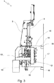
- Fig. 1 shows a blow molding station 1 according to the prior art for reshaping plastic preforms into plastic containers.
- a plurality of such blowing stations 1 is arranged on a rotatable blowing wheel (not shown).
- the reference number 3 in Fig. 1 shows a drive device 3 which is used to actuate the stretching rod 4, ie to move it the stretching rod 4 is used in the stretching direction 5.
- the reference numeral 6 relates to a carrier 6 on which the stretching rod arrangement 4 is arranged.
- the blowing station has two side parts 20, 21 (cf. Fig. 2 ) and a bottom part 22, which together form a cavity in which plastic preforms can be expanded into plastic containers.
- Fig. 2 shows a schematic plan view of a blow molding machine 7 with a feed device 9, a discharge device 8, a plurality of blow stations 1 and an isolator room 10, in which a sterilizing agent can be fed by means of suitable devices 12, 13.
- the movable carrier 2 of the blow molding machine 7 on which the blow stations 1 are arranged is designed as a circular blow wheel 2.
- Exemplary positions in Figure 2 A movable 12 and a stationary 13 device for supplying the sterilizing agent are shown in each case.
- all movable elements (such as for example the blowing stations 1) pass the stationary device 13 for supplying the sterilizing agent and can be exposed to the sterilizing agent.
- the movable device 12 for supplying the sterilizing agent can act on the stationary, radially outer part 15 of the isolator space 9 with the sterilizing agent during one revolution.
- Said device 12 for supplying the sterilizing agent is arranged between two blowing stations 1.
- Fig. 3 shows a schematic representation of a blowing station 1, which is partially located in the interior of an isolator room 9, with the isolator room 9 being able to be fed to the isolator room 9 by means of a movable device 12 (arrows P1).
- the isolator space 9 is closed on three sides by delimitations 16 which follow the movements of the blower wheel 2.
- delimitations 16 which follow the movements of the blower wheel 2.
- they In relation to the stationary delimitation 17 of the isolator space 9, they are moveable by means of seals 18, but are mounted in a gas-tight manner.
- the stretching rod 4 is shielded from the isolator space 9 by means of a seal (for example a bellows) in order to, when the stretching rod 4 is lowered from the unsterile area into the interior of the plastic preform and thus into the sterile area (namely the interior of the isolator space 9), to maintain the sterility of the isolator chamber 9.
- the at least one device 12, 13 for supplying the sterilizing agent is preferably located in the spaces between blowing stations 1.
- the sterilizing agent can be fed to this device 12, 13 via a pipeline system 19. Dosing or throttling devices are optionally located in the line system.
- the degree of atomization can also be specified via nozzles (not shown), so that it is possible to generate a fine aerosol of the sterilizing agent, which remains in the gas phase for a long time without completely settling out.
- nozzles not shown
- other substances such as a washing solution into the isolator room via the device 12, 13 for supplying the sterilizing agent.
- the use of several different sterilizing agents e.g. bactericidal, sporocidal, fungicidal and virucidal sterilizing agents or combinations thereof) is thus possible.
- Fig. 4 shows a schematic representation of a blowing station 1, which is partially located in the interior of an isolator room 9, with the isolator room 9 being able to be fed to the isolator room 9 by means of a stationary device 13 (arrows P2).
- a stationary device 13 As in Figure 3 the isolator space 9 is shown closed on three sides by boundaries 16 which follow the movements of the blower wheel 2.
- a stationary device 13 for supplying the sterilizing agent is arranged in the area of the stationary delimitation 17 of the isolator space 9. The sterilizing agent can be supplied to this via a pipeline system (not shown).
- the stationary delimitation 17 is mounted gas-tight by means of at least one seal 18 in such a way that the blower wheel 2 can move without major energy losses.
- the sterilizing agent can exit the stationary device 13 via outlet openings and be applied directly to the moving parts in the interior of the isolator space 9 that are moved past the blower wheel 2 during rotation.
- the stationary outlet openings can also be nozzles which make it possible to specify the direction in which the sterilizing agent is sprayed.
- the degree of atomization can also be specified via the type or setting of the nozzles. It is also possible to make the nozzles pivotable or rotatable in order to give the emerging sterilizing agent a different preferred flow direction.
Description
Die Erfindung betrifft eine Vorrichtung zum Behandeln von Kunststoffbehältnissen, wobei die Vorrichtung mindestens einen beweglichen Träger aufweist, welcher in einen Isolatorraum angeordnet ist, zu dem ein Sterilisationsmittel zuführbar ist. Außerdem betrifft die Erfindung ein Verfahren zur Sterilisierung eines Isolatorraumes einer Vorrichtung zum Behandeln von Kunststoffbehältnissen mit mindestens einen beweglichen Träger, welcher in einen Isolatorraum angeordnet ist, zu dem ein Sterilisationsmittel zugeführt wird.The invention relates to a device for treating plastic containers, the device having at least one movable carrier which is arranged in an isolator space to which a sterilizing agent can be fed. The invention also relates to a method for sterilizing an isolator space of a device for treating plastic containers with at least one movable carrier which is arranged in an isolator space to which a sterilizing agent is supplied.
Vorrichtungen zum Behandeln von Kunststoffbehältnissen sind aus dem Stand der Technik seit langem bekannt. Ein Beispiel für eine derartige Vorrichtung sind Blasmaschinen zum Umformen von Kunststoffvorformlingen zu Kunststoffbehältnissen. Andere derartige Vorrichtungen sind beispielsweise Ofen (z. B. Mikrowellenöfen) zum Erwärmen von Behältnissen oder Transportsterne für den Transport der Kunststoffbehältnisse. Üblicherweise weisen solche Vorrichtungen mindestens einen beweglichen Träger auf, an dem Einrichtungen zum Aufnehmen der Kunststoffbehältnisse angeordnet sind. Blasmaschinen weisen beispielsweise in der Regel eine Vielzahl von beweglichen Blasformen auf, welche jeweils einen Hohlraum ausbilden, innerhalb dessen die Kunststoffvorformlinge zu Behältnissen umformbar sind und innerhalb derer Vorformlinge aus Kunststoff (Kunststoffvorformlinge) zu Kunststoffbehältnissen expandiert werden. Derartige Blasmaschinen sind üblicherweise rotierende, etwa kreisförmige Anlagen. Dabei nehmen sie Kunststoffvorformlinge an einer bestimmten Position auf und formen während der Rotation und des Überschreitens eines bestimmten Sektors aus diesen die Kunststoffbehältnisse, die wiederum an einer bestimmten Position abgeführt werden.Devices for treating plastic containers have long been known from the prior art. An example of such a device are blow molding machines for reshaping plastic preforms into plastic containers. Other such devices are, for example, ovens (e.g. microwave ovens) for heating containers or transport stars for transporting the plastic containers. Such devices usually have at least one movable carrier on which devices for receiving the plastic containers are arranged. Blow molding machines usually have, for example, a large number of movable blow molds, each of which forms a cavity within which the plastic preforms can be formed into containers and within which plastic preforms (plastic preforms) are expanded into plastic containers. Such blow molding machines are usually rotating, approximately circular systems. In doing so, they pick up plastic preforms at a specific position and shape them as they rotate and when a specific one is exceeded Sector from these the plastic containers, which in turn are discharged at a certain position.
Die
Die
An derartige Blasmaschinen aber auch andere Vorrichtungen zum Behandeln von Kunststoffbehältnissen werden stetig höhere Ansprüche in Bezug auf den Durchsatz und Qualität der produzierten bzw. behandelten Gebinde gestellt. Insbesondere die Hygiene und damit die Keimfreiheit der Gebinde ist in dem Bereich der Abfüllung von Lebensmitteln gefragt. Durch die Sterilisation der verhältnismäßig kleinen Kunststoffvorformlinge und die anschließende sterile (aseptische) Behandlung dieser Kunststoffvorformlinge über den Blasprozess zu dem gewünschten Gebinde bis zum Abfüllvorgang ist es möglich, den Gesamtprozess nicht nur zu beschleunigen, sondern auch die Menge an eingesetztem Sterilisationsmittel zu reduzieren, da lediglich die Oberfläche der gegenüber den fertigen Gebinden deutlich kleineren Vorformlinge sterilisiert werden muss. Damit kann jedoch nicht nur die Menge an Sterilisationsmittel reduziert werden, sondern auch der Prozess deutlich vereinfacht werden. So kann beispielsweise bei der Verwendung von verdampfbaren Sterilisationsmittellösungen (wie z. B. Alkoholen, Chlorwasser, Hypochlorige Säure, Ozon-Lösung, Wasserstoffperoxid, Peroxyessigsäure und anderen) überschüssiges Sterilisationsmittel leicht wieder entfernt werden. Spätestens bei der Erhitzung der Vorformlinge für den Blasprozess entweichen auch die letzten Reste des Sterilisationsmittels, wobei selbstverständlich bei Peroxyden die entsprechenden Sicherheitsaspekte berücksichtigt werden müssen. Eine spätere aufwändige Reinigung und Trocknung der fertigen Gebinde vor dem Abfüllvorgang ist nicht notwendig. Somit ist es trotz des zusätzlichen Aufwandes zur Gewährleistung der Sterilität während des gesamten Produktionsprozesses möglich, die Effizienz deutlich zu steigern.Such blow molding machines, but also other devices for treating plastic containers, are subject to ever higher demands with regard to the throughput and quality of the containers produced or treated. In particular, hygiene and thus the sterility of the containers is in demand in the area of filling foodstuffs. Through the sterilization of the relatively small plastic preforms and the subsequent sterile (aseptic) treatment of these plastic preforms via the blow molding process to the desired container up to the filling process, it is not only possible to accelerate the entire process, but also to reduce the amount of sterilizing agent used, since only the surface of the preforms, which are much smaller than the finished containers, has to be sterilized. However, this can not only reduce the amount of sterilizing agent can be reduced, but also the process can be significantly simplified. For example, when using vaporizable sterilant solutions (such as alcohols, chlorinated water, hypochlorous acid, ozone solution, hydrogen peroxide, peroxyacetic acid and others), excess sterilant can easily be removed again. At the latest when the preforms are heated for the blow molding process, the last remnants of the sterilizing agent also escape, although the relevant safety aspects must of course be taken into account with peroxides. A later time-consuming cleaning and drying of the finished container before the filling process is not necessary. Thus, despite the additional effort to ensure sterility during the entire production process, it is possible to increase the efficiency significantly.
Wichtig für eine hohe Effizienz ist, dass nur ein möglichst geringer Teil der Vorrichtungen zum Behandeln von Behältnissen die aseptischen Bedingungen ausweist. Da das Aufrechterhalten dieser sterilen Bedingungen recht kostenintensiv ist, hat es sich als vorteilhaft erwiesen, lediglich den Bereich der Vorrichtungen zum Behandeln von Behältnissen steril zu halten, in denen sich die sterilen Vorformlinge oder Gebinde befinden. Eine derartige Vorrichtung ist beispielsweise in
In
Die Verwendung von Gasen oder Aerosolen zur Sterilisation von Reinräumen bietet jedoch entscheidende Vorteile gegenüber einer Sterilisation mittels Strahlung. So ist es insbesondere bei der Verwendung von Sterilisationsgasen durch deren großes Diffusionsvermögen möglich, auch in Bereiche vorzudringen, die für Strahlungsquellen unzugänglich sind. Beispielsweise sind bei der Verwendung von UV-Lampen zur Sterilisation bestimmte Bereiche der Blasstation länger dem von diesen Lampen abgestrahlten Licht ausgesetzt als andere Bereiche. Dies beruht unter anderem auf der Form der einzelnen Blasstationen, die zumindest zeitweise einen Schatten in bestimmte Bereiche werfen. In diesen Bereichen ist es unter Umständen möglich, dass sich Keime ablagern, vermehren und zu Kontaminationen führen.However, the use of gases or aerosols for the sterilization of clean rooms offers decisive advantages over sterilization by means of radiation. Especially when using sterilization gases, their high diffusivity makes it possible to penetrate into areas that are inaccessible to radiation sources. For example, when using UV lamps for sterilization, certain areas of the blowing station are exposed to the light emitted by these lamps for longer than other areas. This is based, among other things, on the shape of the individual blowing stations, which at least temporarily cast a shadow in certain areas. In these areas it is possible that germs deposit, multiply and lead to contamination.
Aufgabe der Erfindung ist es daher eine Vorrichtung zum Behandeln von Kunststoffbehältnissen, wobei die Vorrichtung mindestens einen beweglichen Träger aufweist, welcher in einen Isolatorraum angeordnet ist, zu dem ein Sterilisationsmittel zuführbar ist, bereit zu stellen, wobei der Isolatorraum aus beweglichen und unbeweglichen Elementen besteht und die Vorrichtung Einrichtungen zum Zuführen eines Sterilisationsmittels in den Isolatorraum aufweist, die jeweils zu diesen Einrichtungen relativbewegliche Teile innerhalb des Isolatorraums durch die Beaufschlagung mit einem Sterilisationsmittel sterilisieren.The object of the invention is therefore to provide a device for treating plastic containers, the device having at least one movable carrier which is arranged in an isolator space to which a sterilizing agent can be supplied, the isolator space consisting of movable and immovable elements and the device has devices for supplying a sterilizing agent into the isolator space, which in each case sterilize parts within the isolator chamber that are movable relative to these devices by the application of a sterilizing agent.
Diese Aufgabe wird erfindungsgemäß durch eine Vorrichtung nach Anspruch 1 gelöst.This object is achieved according to the invention by a device according to
Eine erfindungsgemäße Vorrichtung zum Behandeln von Kunststoffbehältnissen weist mindestens einen beweglichen Träger auf, welcher in einen Isolatorraum angeordnet ist, zu dem ein Sterilisationsmittel zuführbar ist, wobei der Isolatorraum mindestens zweiteilig ausgebildet ist und eine erste Begrenzung des Isolatorraums während einer Bewegung des beweglichen Trägers positionsfest ist, wohingegen eine zweite Begrenzung des Isolatorraums mit der Vorrichtung bzw. der Blasstation derart verbunden ist, so dass sie dazu geeignet ist, während einer Bewegung des beweglichen Trägers dieser Bewegung zu folgen, wobei die Vorrichtung mindestens eine Einrichtung zum Zuführen des Sterilisationsmittels in den Isolatorraum aufweist, welche dazu geeignet ist, die zu dieser Einrichtung relativbeweglichen innerhalb des Isolatorraums befindlichen Teile der Vorrichtung mit dem Sterilisationsmittel zu beaufschlagen.A device according to the invention for treating plastic containers has at least one movable carrier which is arranged in an isolator space to which a sterilizing agent can be fed, the isolator chamber being at least two-part and a first delimitation of the isolator chamber being fixed in position during a movement of the movable carrier, whereas a second delimitation of the isolator space is connected to the device or the blowing station in such a way that it is suitable for following this movement during a movement of the movable carrier, the device having at least one device for supplying the sterilizing agent into the isolator space, which is suitable for applying the sterilizing agent to the parts of the device that are relatively movable with respect to this device within the isolator space.
Dadurch ist es möglich, das Sterilisationsmittel als Gas oder feinen Nebel (Aerosol) auf die zu desinfizierenden Bereiche der Vorrichtung bzw. der Blasmaschine zu leiten. Es besteht die Möglichkeit, das Sterilisationsmittel auch erwärmt in das Innere des Isolatorraums einzuleiten. Die Einrichtung zum Zuführen des Sterilisationsmittels in den Isolatorraum ist dabei vorzugsweise so ausgebildet, dass sie während der Bewegung der Vorrichtung bzw. des beweglichen Trägers diejenigen Teile innerhalb des Isolatorraums (Reinraums) in etwa gleichmäßig mit Sterilisationsmittel beaufschlagt, die relativbeweglich zu der Einrichtung angeordnet sind. So werden beispielsweise bei einem Blasrad während eines Umlaufs alle in dem Isolatorraum befindlichen Teile des Blasrades an einer stationären Einrichtung zum Zuführen des Sterilisationsmittels in den Isolatorraum vorbeigeführt und mit dem Sterilisationsmittel beaufschlagt. Ebenso ist es möglich, die Einrichtung zum Zuführen des Sterilisationsmittels in dem Isolatorraum beweglich auf dem beweglichen Träger, beispielsweise dem Blasrad anzuordnen, um die feststehenden Teile des Isolatorraums während der Bewegung, beispielsweise eines Umlaufes des Blasrades, mit dem Sterilisationsmittel zu beaufschlagen. Erfindungsgemäß ist eine Vielzahl von Einrichtungen zum Zuführen des Sterilisationsmittels in den Isolatorraum vorgesehen, wobei diese unabhängig voneinander sowohl stationär als auch beweglich gegenüber der mindestens einen Einrichtung zum Aufnehmen der Kunststoffbehältnisse (z. B. einer Blasstation) angeordnet sein können.This makes it possible to direct the sterilizing agent as a gas or fine mist (aerosol) onto the areas of the device or the blow molding machine to be disinfected. There is the possibility of introducing the sterilizing agent into the interior of the isolator chamber in a heated state. The device for supplying the sterilizing agent into the isolator room is preferably designed so that, during the movement of the device or the movable carrier, the sterilizing agent is applied approximately evenly to those parts within the isolator room (clean room) which are arranged to be movable relative to the device. For example, in the case of a blower wheel, all parts of the blower wheel located in the isolator space are guided past a stationary device for supplying the sterilizing agent into the isolator chamber during one revolution and the sterilizing agent is applied to them. It is also possible to arrange the device for supplying the sterilizing agent in the isolator space on the movable support, for example the blowing wheel, in order to move the stationary parts of the isolator space during the movement, For example, one revolution of the blower wheel to apply the sterilizing agent. According to the invention, a plurality of devices for feeding the sterilizing agent into the isolator space is provided, whereby these can be arranged independently of one another both stationary and movable opposite the at least one device for receiving the plastic containers (e.g. a blowing station).
Zur Entfernung von Resten des Sterilisationsmittels nach einem Sterilisationsvorgang im Inneren des Isolatorraums, die evtl. in die produzierten, transportierten oder behandelten Kunststoffbehältnisse gelangen könnten, ist es möglich auch andere Substanzen wie beispielsweise eine Waschlösung über die Einrichtung zum Zuführen des Sterilisationsmittels in den Isolatorraum einzubringen. Ebenso ist beispielsweise die sequenzielle Verwendung von mehreren verschiedenen Sterilisationsmitteln (z. B. bakterizide, sporozide, fungizide und viruzide Sterilisationsmittel oder Kombinationen davon) möglich.To remove residues of the sterilizing agent after a sterilization process inside the isolator room, which could possibly get into the produced, transported or treated plastic containers, it is also possible to introduce other substances such as a washing solution into the isolator room via the device for supplying the sterilizing agent. Likewise, for example, the sequential use of several different sterilizing agents (e.g. bactericidal, sporocidal, fungicidal and virucidal sterilizing agents or combinations thereof) is possible.
Bei der erfindungsgemäßen Vorrichtung handelt es sich insbesondere um eine Blasmaschine. Bei der erfindungsgemäßen Vorrichtung könnte es sich jedoch auch um eine Heizeinrichtung handeln, welche Kunststoffvorformlinge erwärmt oder aber um eine Befüllungseinrichtung zum Befüllen von Behältnissen. Daneben wäre die Erfindung auch für Transporteinrichtungen anwendbar, welche Kunststoffbehältnisse wie Kunststoffvorformlinge oder Kunststoffflaschen transportieren. Allgemein ist die Erfindung bei solchen Anlagen anwendbar, welche bewegliche und insbesondere drehende Teilen sowie einen Reinraum aufweisen.The device according to the invention is in particular a blow molding machine. The device according to the invention could, however, also be a heating device which heats plastic preforms or a filling device for filling containers. In addition, the invention could also be used for transport devices which transport plastic containers such as plastic preforms or plastic bottles. In general, the invention can be used in systems which have movable and, in particular, rotating parts and a clean room.
Erfindungsgemäß weist mindestens eine Einrichtung zum Zuführen des Sterilisationsmittels in den Isolatorraum eine Vielzahl von Düsen auf. Durch diese Düsen ist es einerseits möglich, das Sterilisationsmedium in einer Vorzugsrichtung in den Isolatorraum einzubringen und somit zu gewährleisten, dass auch verhältnismäßig schlecht zugängliche Bereiche des Isolatorraums mit dem Sterilisationsmedium beaufschlagt werden. Außerdem ist es durch diese Düsen möglich, flüssige Sterilisationsmittel und deren Lösungen fein im Inneren des Isolatorraums zu verteilen und ein Aerosol oder Nebel auszubilden. Dieses bleibt längere Zeit stabil, wodurch während einer Bewegung des beweglichen Trägers durch die bei der Bewegung entstehenden Luftverwirbelungen im Inneren des Reinraumes eine äußerst gleichmäßige Verteilung dieser feinen Aerosoltropfen erreicht wird. Damit wird eine gleichmäßige Beaufschlagung der zu sterilisierenden Teile mit dem Sterilisationsmittel gewährleistet. Es ist auch möglich, die Düsen schwenkbar oder drehbar auszuführen, um dem austretenden Sterilisationsmittel eine veränderte bevorzugte Strömungsrichtung zu geben.According to the invention, at least one device for feeding the sterilizing agent into the isolator space has a plurality of nozzles. These nozzles make it possible, on the one hand, to introduce the sterilization medium into the isolator chamber in a preferred direction and thus to ensure that even areas of the isolator chamber that are relatively difficult to access are exposed to the sterilization medium. These nozzles also make it possible to finely distribute liquid sterilizing agents and their solutions in the interior of the isolator space and to form an aerosol or mist. This remains stable for a longer period of time, whereby an extremely even distribution of these fine aerosol droplets is achieved during a movement of the movable carrier due to the air turbulence occurring in the interior of the clean room. This ensures that the sterilizing agent is applied evenly to the parts to be sterilized. It is also possible to make the nozzles pivotable or rotatable in order to give the emerging sterilizing agent a different preferred flow direction.
In einer weiteren bevorzugten Ausführungsform der Vorrichtung sind der bewegliche Teil der Begrenzung des Isolatorraums (Isolatorraumbegrenzung) und der stationäre Teil der Begrenzung des Isolatorraums mittels einer zwischen diesen Begrenzungen angeordneten Dichtung gegenüber der Umgebung derart abgeschlossen, so dass eine Bewegung dieser Begrenzungen gegenüber einander möglich ist, ein Eindringen von Kontaminationen jedoch ausgeschlossen ist. Prinzipiell kann jeder geeignete Dichtungstyp zur Abgrenzung des Isolatorrauminneren gegenüber der unsterilen Umgebung bei gleichzeitiger beweglicher Lagerung des beweglichen Teils der Isolatorraumbegrenzung gegenüber dem stationären Teil der Isolatorraumbegrenzung verwendet werden. Aufgrund der großen Dichtungsfläche und der ständigen Bewegung, die potentiell Abrieb und damit erhöhten Verschleiß der Dichtungselemente verursacht, sind Dichtungen bevorzugt, die ein Sperrmedium verwenden. Vorzugsweise finden sogenannte Wasserschlösser Anwendung.In a further preferred embodiment of the device, the movable part of the delimitation of the isolator space (isolator space delimitation) and the stationary part of the delimitation of the insulator space are closed off from the environment by means of a seal arranged between these delimitations, so that movement of these delimitations with respect to one another is possible, however, the ingress of contamination is excluded. In principle, any suitable type of seal can be used to delimit the interior of the isolator chamber from the non-sterile environment while at the same time moving the movable part of the isolator chamber delimitation against the stationary part of the isolator chamber delimitation. Due to the large sealing surface and the constant movement, which potentially causes abrasion and thus increased wear of the sealing elements, seals that use a barrier medium are preferred. So-called water locks are preferably used.
Zum möglichst effizienten Sterilisieren der in dem Innereren des Reinraums befindlichen Teile der Vorrichtung haben sich positionsfeste Einrichtungen zum Zuführen des Sterilisationsmittels zu dem Isolatorraum als besonders geeignet erwiesen. Daher sind erfindungsgemäß mindestens einige der Einrichtungen zum Zuführen des Sterilisationsmittels zu dem Isolatorraum positionsfest angeordnet. Diese sind bevorzugt derart angeordnet, dass während eines vollständigen Bewegungszykluses alle im Inneren des Reinraums befindlichen Teile der Vorrichtung die Einrichtungen zum Zuführen des Sterilisationsmittels zu dem Isolatorraum in geringem Abstand passieren und so diese Teile direkt mit dem Sterilisationsmittel beaufschlagt werden können. Die Einrichtungen zum Zuführen des Sterilisationsmittels können dabei an einem stationären Träger angeordnet sein oder etwa auch an einer stationären Begrenzungswand des Isolatorraums.For the most efficient possible sterilization of the parts of the device located in the interior of the clean room, fixed-position devices for supplying the sterilizing agent to the isolator room have proven to be particularly suitable. Therefore, according to the invention, at least some of the devices for supplying the sterilizing agent to the isolator space are arranged in a fixed position. These are preferably arranged in such a way that, during a complete movement cycle, all parts of the device located inside the clean room pass the devices for supplying the sterilizing agent to the isolator room at a small distance and so these parts can be directly exposed to the sterilizing agent. The devices for supplying the sterilizing agent can be arranged on a stationary carrier or, for example, also on a stationary boundary wall of the isolator space.
Nur mit einer einzelnen stationären Einrichtung zum Zuführen des Sterilisationsmittels zu dem Isolatorraum ergibt sich jedoch die Problematik, dass die stationären Teile des Isolatorraums oft nur unzureichend mit dem Sterilisationsmittel beaufschlagt werden. In besonders aufwändig ausgebildeten Ausführungsformen von Vorrichtungen zum Behandeln von Kunststoffbehältnissen ist auch durch das bereits beschriebene feine Verteilen des Sterilisationsmittels als Nebel im Inneren des Isolatorraums und eine anschließende Verwirbelung dieses Nebels nicht unbedingt eine ausreichend gleichmäßige Verteilung gewährleistet. Eine ausreichende Sterilisierung der unzugänglichen Bereiche könnte beispielsweise durch gelegentliche separate Sterilisierung erreicht werden. Da dies sehr zeitaufwändig ist und einen Stillstand der gesamten Anlage erfordert, sind Einrichtungen vorteilhaft, die auch eine ausreichende Sterilisierung der stationären Teile gewährleisten.With only a single stationary device for supplying the sterilizing agent to the isolator space, however, the problem arises that the stationary parts of the isolator space are often only insufficiently exposed to the sterilizing agent. In particularly complex embodiments of devices for treating plastic containers, the already described fine distribution of the sterilizing agent as a mist in the interior of the isolator space and a subsequent swirling of this mist does not necessarily ensure a sufficiently uniform distribution. Sufficient sterilization of the inaccessible areas could be achieved, for example, by occasional separate sterilization. Since this is very time consuming and a standstill of the entire system requires facilities that also ensure adequate sterilization of the stationary parts.
In einer bevorzugten Ausführungsform der Vorrichtung sind daher mindestens einige der Einrichtungen zum Zuführen des Sterilisationsmittels zu dem Isolatorraum beweglich angeordnet. Befinden sich diese beweglich angeordneten Einrichtungen zum Zuführen des Sterilisationsmittels zu dem Isolatorraum beispielsweise an oder auf dem beweglichen Träger (z. B. dem Blasrad), passieren sie während eines Bewegungszykluses den gesamten stationären Teil der Isolatorraumbegrenzung und können diesen mit Sterilisationsmitteln beaufschlagen. Bevorzugt sind auch diese Einrichtungen zum Zuführen des Sterilisationsmittels zu dem Isolatorraum als Düsen ausgeführt. Vorteilhaft sind die besagten Einrichtungen zum Zuführen des Sterilisationsmittels derart angeordnet, dass sie das Sterilisationsmittel wenigstens entlang der vollständigen Höhe des Isolatorraums aufbringen.In a preferred embodiment of the device, at least some of the devices for supplying the sterilizing agent to the isolator space are therefore movably arranged. If these movably arranged devices for supplying the sterilizing agent to the isolator room are, for example, on or on the movable carrier (e.g. the blower wheel), they pass through the entire stationary part of the isolator room delimitation during a movement cycle and can apply sterilizing agents to this. These devices for supplying the sterilizing agent to the isolator chamber are also preferably designed as nozzles. Said devices for supplying the sterilizing agent are advantageously arranged in such a way that they apply the sterilizing agent at least along the full height of the isolator space.
Bei einer derartigen Ausführung ergibt sich jedoch die Problematik der kontinuierlichen Zuführung des Sterilisationsmittels zu den beweglichen Einrichtungen zum Zuführen des Sterilisationsmittels zu dem Isolatorraum. Erfindungsgemäß sind daher die beweglich angeordneten Einrichtungen zum Zuführen des Sterilisationsmittels in den Isolatorraum mit einem Drehverteiler in Verbindung, welcher dazu geeignet ist, das Sterilisationsmittel zu den Einrichtungen zuzuführen. Somit ist auf einfache Weise eine kontinuierliche ausreichende Versorgung der Einrichtungen zum Zuführen des Sterilisationsmittels in den Isolatorraum mit Sterilisationsmedium gewährleistet.In such an embodiment, however, the problem arises of the continuous supply of the sterilizing agent to the movable devices for supplying the sterilizing agent to the isolator space. According to the invention, the movably arranged devices for feeding the sterilizing agent into the isolator space are therefore connected to a rotary distributor which is suitable for feeding the sterilizing agent to the devices. A continuous, sufficient supply of the devices for supplying the sterilizing agent to the isolator chamber with sterilizing agent is thus ensured in a simple manner.
In einer weiteren bevorzugten Ausführungsform der Vorrichtung weist die Vorrichtung ein zentrales Reservoir für das Sterilisationsmittel auf. Aus diesem Reservoir können sowohl die beweglichen als auch die stationären Einrichtungen zum Zuführen des Sterilisationsmittels in den Isolatorraum mit dem Sterilisationsmittel versorgt werden. Die Zuführung zu den beweglichen Einrichtungen erfolgt wie bereits erwähnt bevorzugt mittels eines Drehverteilers.In a further preferred embodiment of the device, the device has a central reservoir for the sterilizing agent. Both the movable and the stationary devices for feeding the sterilizing agent into the isolator chamber can be supplied with the sterilizing agent from this reservoir. As already mentioned, the supply to the movable devices is preferably carried out by means of a rotary distributor.
Bevorzugt handelt es sich bei dem beweglichen Träger der Vorrichtung um eine annähernd kreisrunde Vorrichtung. In einer bevorzugten Ausführungsform der Vorrichtung ist daher der bewegliche Träger ein Blasrad mit mindestens einer Blasstation, welches zumindest teilweise im Inneren des Isolatorraums angeordnet ist. Diese Ausführungsform als annähernd kreisrundes Blasrad vereinfacht die Geometrie des Isolatorraums und reduziert gleichzeitig Bereiche im Inneren des Isolatorraums, die für das Sterilisationsmittel schwer zugänglich sind. Vorteilhaft weist der Isolatorraum eine ring- oder torusförmige Gestalt auf, wobei die Blasstationen zumindest teilweise innerhalb des Isolatorraums transportiert werden.The movable support of the device is preferably an approximately circular device. In a preferred embodiment of the device, the movable carrier is therefore a blowing wheel with at least one blowing station, which is at least partially arranged in the interior of the isolator space. This embodiment as an approximately circular blowing wheel simplifies the geometry of the isolator space and at the same time reduces areas in the interior of the isolator space that are difficult to access for the sterilizing agent are. The isolator space advantageously has an annular or toroidal shape, the blowing stations being at least partially transported within the isolator space.
Wie bereits beschrieben handelt es sich bei den Sterilisationsmitteln bevorzugt um leicht verteilbare Substanzen. In einer bevorzugten Ausführungsform liegt das Sterilisationsmittel zum Zeitpunkt des Einspritzens in den Isolatorraum gasförmig oder flüssig vor. Sowohl gasförmig als auch flüssig (bevorzugt als feinverteiltes Aerosol) ist das Sterilisationsmittel leicht verteilbar. Insbesondere während einer Bewegung des Trägers, an dem die einzelnen Einrichtungen zum Behandeln von Kunststoffbehältnissen angeordnet sind, kann es daher durch die entstehenden Luftverwirbelungen fein verteilt werden. Dadurch ist eine ausreichende Beaufschlagung mit dem Sterilisationsmittel auch für die Bereiche im Inneren des Isolatorraums gewährleistet, die bei einer Einspritzung des Sterilisationsmittels nur schwer direkt zugänglich sind.As already described, the sterilizing agents are preferably easily distributable substances. In a preferred embodiment, the sterilizing agent is in gaseous or liquid form at the time of injection into the isolator space. The sterilizing agent is easy to distribute in both gaseous and liquid form (preferably as a finely divided aerosol). In particular, during a movement of the carrier on which the individual devices for treating plastic containers are arranged, it can therefore be finely distributed by the air turbulence that occurs. This also ensures that the sterilization agent is sufficiently applied to the areas in the interior of the isolator chamber which are difficult to access directly when the sterilization agent is injected.
Zur weiteren Verteilung des Sterilisationsmittels im Inneren des Isolatorraums der Vorrichtung ist es in bestimmten Fällen notwendig, für zusätzliche Luftbewegungen zu sorgen. Daher weist in einer weiteren bevorzugten Ausführungsform der Isolatorraum Eingänge für Druckluft auf, die dazu geeignet sind, eine Hochdruckreinigung des Isolatorraums zu ermöglichen. Ebenso ist es durch diese Eingänge möglich, im Inneren des Isolatorraums einen leichten Überdruck zu erzeugen, der verhindert, dass unsteriles Gas in das Innere des Isolatorraums diffundiert und dieses so kontaminiert.For further distribution of the sterilizing agent in the interior of the isolator space of the device, it is necessary in certain cases to ensure additional air movements. Therefore, in a further preferred embodiment, the isolator space has inlets for compressed air which are suitable for enabling high-pressure cleaning of the isolator space. It is also possible through these inlets to generate a slight overpressure inside the isolator space, which prevents unsterile gas from diffusing into the interior of the isolator space and thus contaminating it.
Ein weiterer wesentlicher Aspekt der Erfindung ist ein Verfahren gemäß Anspruch 10 zur Sterilisierung eines Isolatorraumes einer Vorrichtung zum Behandeln von Kunststoffbehältnissen mit mindestens einen beweglichen Träger, welcher in einen Isolatorraum angeordnet ist, zu dem ein Sterilisationsmittel zugeführt wird und wobei der Isolatorraum mindestens zweiteilig ausgebildet ist und eine erste Begrenzung (Begrenzungseinrichtung) des Isolatorraums sich während einer Bewegung des beweglichen Trägers nicht bewegt, wohingegen eine zweite Begrenzung (Begrenzungseinrichtung) des Isolatorraums mit der Vorrichtung derart verbunden ist, dass sie während einer Bewegung des beweglichen Trägers dieser Bewegung folgt.Another essential aspect of the invention is a method according to claim 10 for the sterilization of an isolator space of a device for treating plastic containers with at least one movable carrier, which is arranged in an isolator space to which a sterilization agent is supplied and wherein the isolator space is at least in two parts and a first delimitation (delimitation device) of the isolator space does not move during a movement of the movable support, whereas a second delimitation (delimitation device) of the insulator space is connected to the device in such a way that it follows this movement during a movement of the mobile support.
Durch dieses Verfahren ist es auf sehr einfache und effiziente Weise möglich, das Innere eines Isolatorraums mit Sterilisationsmittel zu beaufschlagen. Während eines Bewegungszykluses des beweglichen Trägers können so nahezu alle gegenüber der Zuführeinrichtung relativbeweglichen Teile mit dem Sterilisationsmittel beaufschlagt werden. Vorteilhaft wird die besagte Relativbewegung durch eine Bewegung eines Trägers bewirkt, an dem die Vorrichtung zum Behandeln von Kunststoffbehältnissen (z. B. eine oder mehrere Blasstationen) angeordnet ist. Ebenso besteht die Möglichkeit, das Sterilisationsmittel auch erhitzt in das Innere des Isolatorraums einzuleiten. Beispielsweise können H2O2, Peroxyessigsäure oder andere Sterilisationsmittel oder deren wässrige Lösungen vor der Einleitung in den Isolatorraum in die Gasphase überführt werden.This method makes it possible, in a very simple and efficient manner, to apply sterilizing agent to the interior of an isolator room. During a cycle of movement of the movable carrier, almost all can thus be compared to the feed device relatively movable parts are acted upon with the sterilizing agent. Said relative movement is advantageously brought about by a movement of a carrier on which the device for treating plastic containers (for example one or more blow molding stations) is arranged. There is also the possibility of introducing the sterilizing agent into the interior of the isolator chamber in a heated state. For example, H 2 O 2 , peroxyacetic acid or other sterilizing agents or their aqueous solutions can be converted into the gas phase before being introduced into the isolator space.
Weitere Vorteile, Ziele und Eigenschaften vorliegender Erfindung werden anhand nachfolgender Beschreibung anliegender Zeichnung erläutert, in welcher beispielhaft eine erfindungsgemäße Vorrichtung am Beispiel einer Blasmaschine mit wenigstens einer Blasstation zum Umformen von Kunststoffvorformlingen zu Kunststoffbehältnissen dargestellt ist, wobei die Blasstation an einem beweglichen Träger angeordnet ist und die Blasmaschine einen Isolatorraum aufweist, zu dem ein Sterilisationsmittel zuführbar ist.Further advantages, goals and properties of the present invention are explained with reference to the following description of the attached drawing, in which an example of a device according to the invention is shown using the example of a blow molding machine with at least one blow station for reshaping plastic preforms into plastic containers, the blow station being arranged on a movable carrier and the The blow molding machine has an isolator chamber to which a sterilizing agent can be fed.
Es zeigen:
- Fig. 1
- eine Blasstation nach dem Stand der Technik,
- Fig. 2
- eine schematische Aufsicht auf eine Blasmaschine mit einer Zuführeinrichtung, einer Abführeinrichtung und einem Isolatorraum, in den mittels geeigneter Einrichtungen ein Sterilisationsmittel zuführbar ist;
- Fig. 3
- eine schematische Darstellung einer Blasstation, die sich teilweise im Inneren eines Isolatorraums befindet, wobei dem Isolatorraum mittels einer beweglichen Einrichtung Sterilisationsmittel zuführbar ist; und
- Fig. 4:
- eine schematische Darstellung einer Blasstation, die sich teilweise im Inneren eines Isolatorraums befindet, wobei dem Isolatorraum mittels einer stationären Einrichtung Sterilisationsmittel zuführbar ist.
- Fig. 1
- a state-of-the-art blow station,
- Fig. 2
- a schematic plan view of a blow molding machine with a feed device, a discharge device and an isolator space, in which a sterilizing agent can be fed by means of suitable devices;
- Fig. 3
- a schematic representation of a blowing station, which is partially located in the interior of an isolator room, wherein the isolator room can be supplied by means of a movable device sterilizing agent; and
- Fig. 4:
- a schematic representation of a blowing station, which is partially located in the interior of an isolator room, wherein the isolator room can be supplied by means of a stationary device sterilization agent.
Über ein Rohrleitungssystem 19 kann dieser Einrichtung 12, 13 das Sterilisationsmittel zugeführt werden. Optional befinden sich Dosier- oder Drosseleinrichtungen im Leitungssystem.The sterilizing agent can be fed to this
Über Austrittsöffnungen kann das Sterilisationsmittel aus der Einrichtung 12, 13 austreten und ins Innere des Isolatorraums 9 bzw. auch an die Innenoberflächen der Begrenzungen 16, 17 gelangen. Über die Form und Ausrichtung der Austrittsöffnungen kann die Richtung vorgegeben werden, in der das Sterilisationsmittel abgegeben wird.The sterilizing agent can emerge from the
Ebenso kann über (nicht gezeigte) Düsen auch der Grad der Zerstäubung vorgegeben werden, so dass es möglich ist, ein feines Aerosol des Sterilisationsmittels zu erzeugen, welches längere Zeit in der Gasphase verbleibt, ohne sich vollständig abzusetzen. Um nach einem Sterilisationsvorgang zu vermeiden, dass Reste des Aerosols verbleiben und evtl. in das Innere der produzierten Kunststoffbehältnisse gelangen, ist es möglich, auch andere Substanzen wie beispielsweise eine Waschlösung über die Einrichtung 12, 13 zum Zuführen des Sterilisationsmittels in den Isolatorraum einzubringen. Auch die Verwendung von mehreren verschiedenen Sterilisationsmitteln (z. B. bakterizide, sporozide, fungizide und viruzide Sterilisationsmittel oder Kombinationen davon) ist somit möglich.The degree of atomization can also be specified via nozzles (not shown), so that it is possible to generate a fine aerosol of the sterilizing agent, which remains in the gas phase for a long time without completely settling out. In order to avoid residues of the aerosol remaining after a sterilization process and possibly getting into the interior of the plastic containers produced, it is also possible to introduce other substances such as a washing solution into the isolator room via the
Die Anmelderin behält sich vor, sämtliche in den Anmeldungsunterlagen offenbarten Merkmale als erfindungswesentlich zu beanspruchen, sofern diese einzeln oder in Kombination gegenüber dem Stand der Technik neu sind.The applicant reserves the right to claim all features disclosed in the application documents as essential to the invention, provided that they are new to the state of the art, individually or in combination.
- 11
- BlasstationBlow station
- 22
- Träger / BlasradCarrier / blowing wheel
- 33
- AntriebseinrichtungDrive device
- 44th
- ReckstangeHorizontal bar
- 55
- DehnungsrichtungStretch direction
- 66th
- Trägercarrier
- 77th
- Vorrichtung zum Behandeln von Kunststoffbehältnissen (z. B. Blasmaschine)Device for treating plastic containers (e.g. blow molding machine)
- 88th
- AbführeinrichtungDischarge device
- 99
- ZuführeinrichtungFeeding device
- 1010
- IsolatorraumIsolator room
- 1212th
- bewegliche Einrichtung zum Zuführen des SterilisationsmittelsMovable device for supplying the sterilizing agent
- 1313th
- stationäre Einrichtung zum Zuführen des Sterilisationsmittelsstationary device for supplying the sterilizing agent
- 1414th
- radial innenliegender Teils des Isolatorraumsradially inner part of the isolator space
- 1515th
- radial außenliegender Teil des Isolatorraumsradially outer part of the isolator space
- 1616
- bewegliche Begrenzungenmovable limits
- 1717th
- stationäre Begrenzungstationary limitation
- 1818th
- Dichtungpoetry
- 1919th
- RohrleitungssystemPiping system
- 2020th
- erstes Seitenteilfirst side part
- 2121st
- zweites Seitenteilsecond side part
- 2222nd
- BodenteilBottom part
Claims (11)
- An apparatus (7) for the treatment of plastics material containers, wherein the apparatus (7) has at least one movable support (2) which is arranged in an isolator room (10) to which a sterilization agent is capable of being supplied, wherein the isolator room (10) is constructed in at least two parts and a first boundary (15) of the isolator room (10) is fixed in position during a movement of the movable support (2), whereas a second boundary (14) of the isolator room (10) is connected to the apparatus (7) in such a way that it is suitable, during a movement of the movable support (2), for following this movement, wherein the apparatus (7) has at least one device (12, 13) for supplying the sterilization agent into the isolator room (10), which device (12, 13) is suitable for acting with the sterilization agent upon the parts of the apparatus (7) movable relative to this device (12, 13) and situated inside the isolator room (10),
wherein the at least one device (12) for supplying the sterilization agent to the isolator room (10) is connected to a rotary distributor,
and wherein
the device (12, 13) for supplying the sterilization agent into the isolator room (10) has a plurality of nozzles,
characterized in that
at least one of the devices for supplying the sterilization agent to the isolator room (10) is arranged fixed in their position and at least one of the devices (12) for supplying the sterilization agent to the isolator room (10) is arranged in a movable manner. - An apparatus (7) according to claim 1,
characterized in that
the device (12) being arranged movably to the isolator room (10) for supplying the sterilization agent into the isolator room (10) has a plurality of nozzles. - An apparatus (7) according to one of the preceding claims,
characterized in that
the movable part of the boundary (14) of the isolator room (10) and the stationary part of the boundary (15) of the isolator room (10) are closed off from the environment by means of a seal (18) arranged between these boundaries, in such a way that a movement of these boundaries (14, 15) with respect to each other is possible, but penetration by contamination is eliminated. - An apparatus (7) according to any one of the preceding claims,
characterized in that
at least some of the devices (12) for supplying the sterilization agent to the isolator room (10) are arranged in a movable manner. - An apparatus (7) according to any one of the preceding claims,
characterized in that
the movably arranged devices (12) for supplying the sterilization agent into the isolator room (10) are connected to a rotary distributor which is suitable for supplying the sterilization agent to the devices (12). - An apparatus (7) according to any one of the preceding claims,
characterized in that
the apparatus (7) has a central reservoir for the sterilization agent. - An apparatus (7) according to any one of the preceding claims,
characterized in that
the movable support (2) is a blowing wheel (2) with at least one blowing station (1), which is arranged at least in part in the interior of the isolator room (10). - An apparatus (7) according to any one of the preceding claims,
characterized in that
the devices (12, 13) for supplying the sterilization agent into the isolator room (10) are suitable for gaseous or liquid supply of the sterilization agent into the isolator room. - An apparatus (7) according to any one of the preceding claims,
characterized in that
the isolator room (10) has inlets for compressed air, which are suitable for permitting a high-pressure cleaning of the isolator room (10). - A method of sterilizing an insulator room (10) of an apparatus (7) for the treatment of plastics material containers, with at least one movable support (2) which is arranged in an insulator room (10) to which a sterilization agent is supplied, wherein the isolator room (10) is designed in at least two parts and a first boundary (15) of the isolator room (10) does not move during a movement of the apparatus (7), whereas a second boundary (14) of the isolator room (10) is connected to the apparatus (7) in such a way that during a movement of the apparatus (7) it follows this movement, wherein at least one device (12, 13) is provided for supplying the sterilization agent into the isolator room (10), by which the parts of the blow moulding machine (7) movable relative to this device (12, 13) and present inside the isolator room (10) are acted upon with the sterilization agent, wherein the sterilization agent is supplied to the isolator room (10) with at least one device (12) for supplying the sterilization agent, which device is connected to a rotary distributor,
wherein
the device (12, 13) for supplying the sterilization agent into the isolator room (10) has a plurality of nozzles,
characterized in that
at least one of the devices for supplying the sterilization agent to the isolator room (10) is arranged fixed in their position and at least one of the devices (12) for supplying the sterilization agent to the isolator room (10) is arranged in a movable manner. - A method of sterilizing an insulator room (10) of an apparatus (7) for the treatment of plastics material containers according to claim 10,
characterized in that
the sterilizing agent is supplied to the isolator room (10) in gaseous or liquid form at the time of injection into the isolator room (10).
Applications Claiming Priority (1)
| Application Number | Priority Date | Filing Date | Title |
|---|---|---|---|
| DE102010045832.5A DE102010045832B4 (en) | 2010-09-20 | 2010-09-20 | Aseptic sterilization unit for clean rooms on a blowing wheel |
Publications (2)
| Publication Number | Publication Date |
|---|---|
| EP2431058A1 EP2431058A1 (en) | 2012-03-21 |
| EP2431058B1 true EP2431058B1 (en) | 2021-05-12 |
Family
ID=44674497
Family Applications (1)
| Application Number | Title | Priority Date | Filing Date |
|---|---|---|---|
| EP11181565.0A Active EP2431058B1 (en) | 2010-09-20 | 2011-09-16 | Aseptic sterilisation unit for clean room |
Country Status (4)
| Country | Link |
|---|---|
| US (1) | US8920745B2 (en) |
| EP (1) | EP2431058B1 (en) |
| CN (1) | CN102407600B (en) |
| DE (1) | DE102010045832B4 (en) |
Families Citing this family (12)
| Publication number | Priority date | Publication date | Assignee | Title |
|---|---|---|---|---|
| DE102010022130A1 (en) | 2010-05-20 | 2011-11-24 | Krones Ag | Device for forming plastic preforms with sterile space |
| DE102011013118A1 (en) * | 2011-03-04 | 2012-09-06 | Krones Aktiengesellschaft | Blowing machine with sterile room and media supply in the sterile room |
| DE102011013121A1 (en) * | 2011-03-04 | 2012-09-20 | Krones Aktiengesellschaft | Blow molding machine with sterile room and heating |
| DE102011102090B4 (en) | 2011-05-19 | 2018-02-08 | Khs Corpoplast Gmbh | Method for cleaning and / or disinfecting a device for producing containers filled with a liquid product and apparatus |
| DE102012206636A1 (en) * | 2012-04-23 | 2013-10-24 | Krones Ag | Device for producing and filling a product container with plastic liner |
| DE102012106308A1 (en) * | 2012-07-13 | 2014-05-22 | Krones Ag | Sterile heating device for plastic preforms |
| DE102012106310A1 (en) | 2012-07-13 | 2014-05-22 | Krones Ag | Device for heating plastic preforms with sterile space |
| DE102012107811B4 (en) * | 2012-08-24 | 2024-02-22 | Krones Aktiengesellschaft | Heating device and a device and a method for heating plastic preforms in a clean room |
| FR3020007B1 (en) * | 2014-04-17 | 2016-05-20 | Sidel Participations | INSTALLATION FOR THE PRODUCTION OF CONTAINERS COMPRISING A DEVICE FOR DISINFECTING A TRANSFER WHEEL |
| EP3827964B1 (en) * | 2016-09-28 | 2023-08-23 | Dai Nippon Printing Co., Ltd. | Aseptic blow molding machine and aseptic blow molding method |
| DE102017115824A1 (en) * | 2017-07-13 | 2019-01-17 | Krones Ag | Device and method for sterilizing a surface of a container treatment plant |
| CN115230123B (en) * | 2022-05-24 | 2023-11-17 | 江苏新美星包装机械股份有限公司 | Blow molding machine with sterile environment and sterile method thereof |
Family Cites Families (8)
| Publication number | Priority date | Publication date | Assignee | Title |
|---|---|---|---|---|
| US5671591A (en) * | 1995-05-01 | 1997-09-30 | Ashland, Inc. | Integrated container moulding and filling facility |
| FR2766121B1 (en) * | 1997-07-18 | 1999-09-17 | Sidel Sa | PROCESS FOR THE MANUFACTURE OF STERILE CONTAINERS, AND INSTALLATION FOR THE IMPLEMENTATION |
| DE102007017938C5 (en) | 2007-04-13 | 2017-09-21 | Khs Gmbh | Container manufacturing apparatus and mold production method |
| DE102008038141A1 (en) | 2008-08-18 | 2010-02-25 | Krones Ag | Device for forming plastic preforms with sterile space |
| ATE539871T1 (en) * | 2009-04-28 | 2012-01-15 | Gea Procomac Spa | DEVICE FOR PRODUCING CONTAINERS FROM PREFORMS |
| DE202009010813U1 (en) | 2009-08-12 | 2009-12-24 | Krones Ag | Radiation treatment in the annular channel |
| DE102010013132A1 (en) * | 2010-03-26 | 2011-09-29 | Krones Ag | Apparatus for treating containers with height-adjustable isolator |
| DE102010022130A1 (en) * | 2010-05-20 | 2011-11-24 | Krones Ag | Device for forming plastic preforms with sterile space |
-
2010
- 2010-09-20 DE DE102010045832.5A patent/DE102010045832B4/en active Active
-
2011
- 2011-09-16 EP EP11181565.0A patent/EP2431058B1/en active Active
- 2011-09-19 US US13/236,623 patent/US8920745B2/en active Active
- 2011-09-19 CN CN201110278593.4A patent/CN102407600B/en active Active
Non-Patent Citations (1)
| Title |
|---|
| None * |
Also Published As
| Publication number | Publication date |
|---|---|
| CN102407600B (en) | 2015-05-13 |
| DE102010045832B4 (en) | 2023-10-19 |
| CN102407600A (en) | 2012-04-11 |
| US8920745B2 (en) | 2014-12-30 |
| EP2431058A1 (en) | 2012-03-21 |
| DE102010045832A1 (en) | 2012-03-22 |
| US20120070340A1 (en) | 2012-03-22 |
Similar Documents
| Publication | Publication Date | Title |
|---|---|---|
| EP2431058B1 (en) | Aseptic sterilisation unit for clean room | |
| EP2371397B1 (en) | Device for sterilising containers | |
| EP2138298B1 (en) | Device and method for manufacturing plastic containers | |
| EP2161202B1 (en) | Electron beam sterilisation for containers | |
| EP2146838B1 (en) | Apparatus for the production of receptacles, and method for the production of molded articles | |
| EP2491955B1 (en) | Method and device for sterilising containers | |
| EP2604410B1 (en) | Device for for reforming plastic blanks, beverage filling system and method | |
| EP2594495B1 (en) | Apparatus, system and method with internally gripping holding element for container sterilization by means of electron beams | |
| EP2595790B1 (en) | Method and device for sterilizing preforms | |
| EP2594493B1 (en) | Device for internal and external sterilisation of preforms by means of charge carrier rays and corresponding method and handling system | |
| WO2010020529A2 (en) | Apparatus for shaping plastic preforms, comprising a sterile chamber | |
| EP2746029B1 (en) | Method and device for sterilising containers | |
| EP2420258B1 (en) | Device for handling packaging | |
| EP2796269B1 (en) | Device and method for the sterilisation of the outside of plastic preforms | |
| EP2687478A1 (en) | Method and device for treating container closures | |
| EP2818302A1 (en) | Method and device for forming plastic preforms into plastic containers | |
| DE202013008055U1 (en) | Device for forming plastic preforms with clean room | |
| EP3036079A1 (en) | Device and method for producing sterile containers | |
| DE102020132324A1 (en) | Device and method for sterilizing plastic preforms | |
| EP3036080B1 (en) | Device and method for producing sterile containers | |
| EP3036082A1 (en) | Method and device for blow-molding containers which are sterile at least in some areas | |
| WO2019121723A1 (en) | Device for treating containers | |
| DE102015105994A1 (en) | Device for producing containers with discharge of plastic preforms | |
| EP4296034A1 (en) | System and method for operating a system for producing filled plastic containers from sterile plastic preforms |
Legal Events
| Date | Code | Title | Description |
|---|---|---|---|
| PUAI | Public reference made under article 153(3) epc to a published international application that has entered the european phase |
Free format text: ORIGINAL CODE: 0009012 |
|
| AK | Designated contracting states |
Kind code of ref document: A1 Designated state(s): AL AT BE BG CH CY CZ DE DK EE ES FI FR GB GR HR HU IE IS IT LI LT LU LV MC MK MT NL NO PL PT RO RS SE SI SK SM TR |
|
| AX | Request for extension of the european patent |
Extension state: BA ME |
|
| 17P | Request for examination filed |
Effective date: 20120912 |
|
| 17Q | First examination report despatched |
Effective date: 20151104 |
|
| GRAP | Despatch of communication of intention to grant a patent |
Free format text: ORIGINAL CODE: EPIDOSNIGR1 |
|
| INTG | Intention to grant announced |
Effective date: 20160624 |
|
| GRAJ | Information related to disapproval of communication of intention to grant by the applicant or resumption of examination proceedings by the epo deleted |
Free format text: ORIGINAL CODE: EPIDOSDIGR1 |
|
| STAA | Information on the status of an ep patent application or granted ep patent |
Free format text: STATUS: EXAMINATION IS IN PROGRESS |
|
| INTC | Intention to grant announced (deleted) | ||
| GRAP | Despatch of communication of intention to grant a patent |
Free format text: ORIGINAL CODE: EPIDOSNIGR1 |
|
| STAA | Information on the status of an ep patent application or granted ep patent |
Free format text: STATUS: GRANT OF PATENT IS INTENDED |
|
| INTG | Intention to grant announced |
Effective date: 20171123 |
|
| GRAS | Grant fee paid |
Free format text: ORIGINAL CODE: EPIDOSNIGR3 |
|
| GRAJ | Information related to disapproval of communication of intention to grant by the applicant or resumption of examination proceedings by the epo deleted |
Free format text: ORIGINAL CODE: EPIDOSDIGR1 |
|
| GRAL | Information related to payment of fee for publishing/printing deleted |
Free format text: ORIGINAL CODE: EPIDOSDIGR3 |
|
| STAA | Information on the status of an ep patent application or granted ep patent |
Free format text: STATUS: EXAMINATION IS IN PROGRESS |
|
| INTC | Intention to grant announced (deleted) | ||
| RIN1 | Information on inventor provided before grant (corrected) |
Inventor name: VOTH, KLAUS |
|
| GRAP | Despatch of communication of intention to grant a patent |
Free format text: ORIGINAL CODE: EPIDOSNIGR1 |
|
| STAA | Information on the status of an ep patent application or granted ep patent |
Free format text: STATUS: GRANT OF PATENT IS INTENDED |
|
| INTG | Intention to grant announced |
Effective date: 20201027 |
|
| GRAS | Grant fee paid |
Free format text: ORIGINAL CODE: EPIDOSNIGR3 |
|
| GRAA | (expected) grant |
Free format text: ORIGINAL CODE: 0009210 |
|
| STAA | Information on the status of an ep patent application or granted ep patent |
Free format text: STATUS: THE PATENT HAS BEEN GRANTED |
|
| AK | Designated contracting states |
Kind code of ref document: B1 Designated state(s): AL AT BE BG CH CY CZ DE DK EE ES FI FR GB GR HR HU IE IS IT LI LT LU LV MC MK MT NL NO PL PT RO RS SE SI SK SM TR |
|
| REG | Reference to a national code |
Ref country code: GB Ref legal event code: FG4D Free format text: NOT ENGLISH |
|
| REG | Reference to a national code |
Ref country code: CH Ref legal event code: EP |
|
| REG | Reference to a national code |
Ref country code: DE Ref legal event code: R096 Ref document number: 502011017138 Country of ref document: DE |
|
| REG | Reference to a national code |
Ref country code: IE Ref legal event code: FG4D Free format text: LANGUAGE OF EP DOCUMENT: GERMAN |
|
| REG | Reference to a national code |
Ref country code: AT Ref legal event code: REF Ref document number: 1391740 Country of ref document: AT Kind code of ref document: T Effective date: 20210615 |
|
| REG | Reference to a national code |
Ref country code: LT Ref legal event code: MG9D |
|
| REG | Reference to a national code |
Ref country code: NL Ref legal event code: MP Effective date: 20210512 |
|
| PG25 | Lapsed in a contracting state [announced via postgrant information from national office to epo] |
Ref country code: FI Free format text: LAPSE BECAUSE OF FAILURE TO SUBMIT A TRANSLATION OF THE DESCRIPTION OR TO PAY THE FEE WITHIN THE PRESCRIBED TIME-LIMIT Effective date: 20210512 Ref country code: LT Free format text: LAPSE BECAUSE OF FAILURE TO SUBMIT A TRANSLATION OF THE DESCRIPTION OR TO PAY THE FEE WITHIN THE PRESCRIBED TIME-LIMIT Effective date: 20210512 Ref country code: BG Free format text: LAPSE BECAUSE OF FAILURE TO SUBMIT A TRANSLATION OF THE DESCRIPTION OR TO PAY THE FEE WITHIN THE PRESCRIBED TIME-LIMIT Effective date: 20210812 Ref country code: HR Free format text: LAPSE BECAUSE OF FAILURE TO SUBMIT A TRANSLATION OF THE DESCRIPTION OR TO PAY THE FEE WITHIN THE PRESCRIBED TIME-LIMIT Effective date: 20210512 |
|
| PG25 | Lapsed in a contracting state [announced via postgrant information from national office to epo] |
Ref country code: PL Free format text: LAPSE BECAUSE OF FAILURE TO SUBMIT A TRANSLATION OF THE DESCRIPTION OR TO PAY THE FEE WITHIN THE PRESCRIBED TIME-LIMIT Effective date: 20210512 Ref country code: PT Free format text: LAPSE BECAUSE OF FAILURE TO SUBMIT A TRANSLATION OF THE DESCRIPTION OR TO PAY THE FEE WITHIN THE PRESCRIBED TIME-LIMIT Effective date: 20210913 Ref country code: NO Free format text: LAPSE BECAUSE OF FAILURE TO SUBMIT A TRANSLATION OF THE DESCRIPTION OR TO PAY THE FEE WITHIN THE PRESCRIBED TIME-LIMIT Effective date: 20210812 Ref country code: ES Free format text: LAPSE BECAUSE OF FAILURE TO SUBMIT A TRANSLATION OF THE DESCRIPTION OR TO PAY THE FEE WITHIN THE PRESCRIBED TIME-LIMIT Effective date: 20210512 Ref country code: GR Free format text: LAPSE BECAUSE OF FAILURE TO SUBMIT A TRANSLATION OF THE DESCRIPTION OR TO PAY THE FEE WITHIN THE PRESCRIBED TIME-LIMIT Effective date: 20210813 Ref country code: LV Free format text: LAPSE BECAUSE OF FAILURE TO SUBMIT A TRANSLATION OF THE DESCRIPTION OR TO PAY THE FEE WITHIN THE PRESCRIBED TIME-LIMIT Effective date: 20210512 Ref country code: IS Free format text: LAPSE BECAUSE OF FAILURE TO SUBMIT A TRANSLATION OF THE DESCRIPTION OR TO PAY THE FEE WITHIN THE PRESCRIBED TIME-LIMIT Effective date: 20210912 Ref country code: RS Free format text: LAPSE BECAUSE OF FAILURE TO SUBMIT A TRANSLATION OF THE DESCRIPTION OR TO PAY THE FEE WITHIN THE PRESCRIBED TIME-LIMIT Effective date: 20210512 Ref country code: SE Free format text: LAPSE BECAUSE OF FAILURE TO SUBMIT A TRANSLATION OF THE DESCRIPTION OR TO PAY THE FEE WITHIN THE PRESCRIBED TIME-LIMIT Effective date: 20210512 |
|
| PG25 | Lapsed in a contracting state [announced via postgrant information from national office to epo] |
Ref country code: NL Free format text: LAPSE BECAUSE OF FAILURE TO SUBMIT A TRANSLATION OF THE DESCRIPTION OR TO PAY THE FEE WITHIN THE PRESCRIBED TIME-LIMIT Effective date: 20210512 |
|
| PG25 | Lapsed in a contracting state [announced via postgrant information from national office to epo] |
Ref country code: RO Free format text: LAPSE BECAUSE OF FAILURE TO SUBMIT A TRANSLATION OF THE DESCRIPTION OR TO PAY THE FEE WITHIN THE PRESCRIBED TIME-LIMIT Effective date: 20210512 Ref country code: CZ Free format text: LAPSE BECAUSE OF FAILURE TO SUBMIT A TRANSLATION OF THE DESCRIPTION OR TO PAY THE FEE WITHIN THE PRESCRIBED TIME-LIMIT Effective date: 20210512 Ref country code: DK Free format text: LAPSE BECAUSE OF FAILURE TO SUBMIT A TRANSLATION OF THE DESCRIPTION OR TO PAY THE FEE WITHIN THE PRESCRIBED TIME-LIMIT Effective date: 20210512 Ref country code: EE Free format text: LAPSE BECAUSE OF FAILURE TO SUBMIT A TRANSLATION OF THE DESCRIPTION OR TO PAY THE FEE WITHIN THE PRESCRIBED TIME-LIMIT Effective date: 20210512 Ref country code: SK Free format text: LAPSE BECAUSE OF FAILURE TO SUBMIT A TRANSLATION OF THE DESCRIPTION OR TO PAY THE FEE WITHIN THE PRESCRIBED TIME-LIMIT Effective date: 20210512 Ref country code: SM Free format text: LAPSE BECAUSE OF FAILURE TO SUBMIT A TRANSLATION OF THE DESCRIPTION OR TO PAY THE FEE WITHIN THE PRESCRIBED TIME-LIMIT Effective date: 20210512 |
|
| REG | Reference to a national code |
Ref country code: DE Ref legal event code: R097 Ref document number: 502011017138 Country of ref document: DE |
|
| PLBE | No opposition filed within time limit |
Free format text: ORIGINAL CODE: 0009261 |
|
| STAA | Information on the status of an ep patent application or granted ep patent |
Free format text: STATUS: NO OPPOSITION FILED WITHIN TIME LIMIT |
|
| 26N | No opposition filed |
Effective date: 20220215 |
|
| REG | Reference to a national code |
Ref country code: CH Ref legal event code: PL |
|
| REG | Reference to a national code |
Ref country code: BE Ref legal event code: MM Effective date: 20210930 |
|
| GBPC | Gb: european patent ceased through non-payment of renewal fee |
Effective date: 20210916 |
|
| PG25 | Lapsed in a contracting state [announced via postgrant information from national office to epo] |
Ref country code: IS Free format text: LAPSE BECAUSE OF FAILURE TO SUBMIT A TRANSLATION OF THE DESCRIPTION OR TO PAY THE FEE WITHIN THE PRESCRIBED TIME-LIMIT Effective date: 20210912 Ref country code: MC Free format text: LAPSE BECAUSE OF FAILURE TO SUBMIT A TRANSLATION OF THE DESCRIPTION OR TO PAY THE FEE WITHIN THE PRESCRIBED TIME-LIMIT Effective date: 20210512 Ref country code: AL Free format text: LAPSE BECAUSE OF FAILURE TO SUBMIT A TRANSLATION OF THE DESCRIPTION OR TO PAY THE FEE WITHIN THE PRESCRIBED TIME-LIMIT Effective date: 20210512 |
|
| PG25 | Lapsed in a contracting state [announced via postgrant information from national office to epo] |
Ref country code: LU Free format text: LAPSE BECAUSE OF NON-PAYMENT OF DUE FEES Effective date: 20210916 Ref country code: IE Free format text: LAPSE BECAUSE OF NON-PAYMENT OF DUE FEES Effective date: 20210916 Ref country code: GB Free format text: LAPSE BECAUSE OF NON-PAYMENT OF DUE FEES Effective date: 20210916 Ref country code: BE Free format text: LAPSE BECAUSE OF NON-PAYMENT OF DUE FEES Effective date: 20210930 |
|
| PG25 | Lapsed in a contracting state [announced via postgrant information from national office to epo] |
Ref country code: LI Free format text: LAPSE BECAUSE OF NON-PAYMENT OF DUE FEES Effective date: 20210930 Ref country code: CH Free format text: LAPSE BECAUSE OF NON-PAYMENT OF DUE FEES Effective date: 20210930 |
|
| REG | Reference to a national code |
Ref country code: AT Ref legal event code: MM01 Ref document number: 1391740 Country of ref document: AT Kind code of ref document: T Effective date: 20210916 |
|
| PG25 | Lapsed in a contracting state [announced via postgrant information from national office to epo] |
Ref country code: AT Free format text: LAPSE BECAUSE OF NON-PAYMENT OF DUE FEES Effective date: 20210916 |
|
| PG25 | Lapsed in a contracting state [announced via postgrant information from national office to epo] |
Ref country code: HU Free format text: LAPSE BECAUSE OF FAILURE TO SUBMIT A TRANSLATION OF THE DESCRIPTION OR TO PAY THE FEE WITHIN THE PRESCRIBED TIME-LIMIT; INVALID AB INITIO Effective date: 20110916 Ref country code: CY Free format text: LAPSE BECAUSE OF FAILURE TO SUBMIT A TRANSLATION OF THE DESCRIPTION OR TO PAY THE FEE WITHIN THE PRESCRIBED TIME-LIMIT Effective date: 20210512 |
|
| P01 | Opt-out of the competence of the unified patent court (upc) registered |
Effective date: 20230523 |
|
| PGFP | Annual fee paid to national office [announced via postgrant information from national office to epo] |
Ref country code: IT Payment date: 20230810 Year of fee payment: 13 |
|
| PGFP | Annual fee paid to national office [announced via postgrant information from national office to epo] |
Ref country code: FR Payment date: 20230808 Year of fee payment: 13 Ref country code: DE Payment date: 20230802 Year of fee payment: 13 |