EP2430968A2 - Wasserführendes Haushaltsgerät, insbesondere Geschirrspülmaschinen - Google Patents
Wasserführendes Haushaltsgerät, insbesondere Geschirrspülmaschinen Download PDFInfo
- Publication number
- EP2430968A2 EP2430968A2 EP11179160A EP11179160A EP2430968A2 EP 2430968 A2 EP2430968 A2 EP 2430968A2 EP 11179160 A EP11179160 A EP 11179160A EP 11179160 A EP11179160 A EP 11179160A EP 2430968 A2 EP2430968 A2 EP 2430968A2
- Authority
- EP
- European Patent Office
- Prior art keywords
- water
- conducting
- appliance according
- connecting piece
- household appliance
- Prior art date
- Legal status (The legal status is an assumption and is not a legal conclusion. Google has not performed a legal analysis and makes no representation as to the accuracy of the status listed.)
- Granted
Links
Images

Classifications
-
- A—HUMAN NECESSITIES
- A47—FURNITURE; DOMESTIC ARTICLES OR APPLIANCES; COFFEE MILLS; SPICE MILLS; SUCTION CLEANERS IN GENERAL
- A47L—DOMESTIC WASHING OR CLEANING; SUCTION CLEANERS IN GENERAL
- A47L15/00—Washing or rinsing machines for crockery or tableware
- A47L15/42—Details
- A47L15/4214—Water supply, recirculation or discharge arrangements; Devices therefor
- A47L15/4225—Arrangements or adaption of recirculation or discharge pumps
-
- A—HUMAN NECESSITIES
- A47—FURNITURE; DOMESTIC ARTICLES OR APPLIANCES; COFFEE MILLS; SPICE MILLS; SUCTION CLEANERS IN GENERAL
- A47L—DOMESTIC WASHING OR CLEANING; SUCTION CLEANERS IN GENERAL
- A47L15/00—Washing or rinsing machines for crockery or tableware
- A47L15/42—Details
- A47L15/4214—Water supply, recirculation or discharge arrangements; Devices therefor
- A47L15/4219—Water recirculation
-
- A—HUMAN NECESSITIES
- A47—FURNITURE; DOMESTIC ARTICLES OR APPLIANCES; COFFEE MILLS; SPICE MILLS; SUCTION CLEANERS IN GENERAL
- A47L—DOMESTIC WASHING OR CLEANING; SUCTION CLEANERS IN GENERAL
- A47L15/00—Washing or rinsing machines for crockery or tableware
- A47L15/42—Details
- A47L15/4246—Details of the tub
-
- F—MECHANICAL ENGINEERING; LIGHTING; HEATING; WEAPONS; BLASTING
- F16—ENGINEERING ELEMENTS AND UNITS; GENERAL MEASURES FOR PRODUCING AND MAINTAINING EFFECTIVE FUNCTIONING OF MACHINES OR INSTALLATIONS; THERMAL INSULATION IN GENERAL
- F16L—PIPES; JOINTS OR FITTINGS FOR PIPES; SUPPORTS FOR PIPES, CABLES OR PROTECTIVE TUBING; MEANS FOR THERMAL INSULATION IN GENERAL
- F16L27/00—Adjustable joints; Joints allowing movement
- F16L27/10—Adjustable joints; Joints allowing movement comprising a flexible connection only
- F16L27/113—Adjustable joints; Joints allowing movement comprising a flexible connection only the ends of the pipe being interconnected by a rigid sleeve
Definitions
- the invention relates to a water-conducting household appliance, in particular a dishwasher, with two liquid-conducting components, wherein a liquid-conducting component has a molded connecting piece, which is liquid-tightly connected to the other liquid-conducting component by a joining movement in the axial direction of the connecting piece.
- Water-conducting household appliances such as dishwashers, have in the bottom region of the washing compartment to a sump, to which a circulating pump is connected. In the rinsing operation, the rinsing liquid collected in the sump is sucked by the circulation pump and directed to sprayers of the dishwasher. Between the pump pot and the circulation pump a noise decoupling is provided. This prevents transmission of operational vibrations starting from the circulation pump on the washing.
- a seal made of a thermoplastic elastomer may be integrally formed on a circulating pump, which serves as a connecting piece for establishing a connection with a further liquid-conducting component, such. B. serves a line section. To produce a liquid-tight connection, however, the installation of an ear clamp or wire clamp is required, which increases the assembly costs.
- a vibration damper which is designed to be rigid in the axial direction for performing the joining movement and is designed to be deformable about an axis of rotation for receiving torsional oscillations between the two components.
- the vibration damper may be assigned to the connecting piece and be designed as a vibration damping portion of the connecting piece.
- the vibration damper is designed so stiff that an assembly by a joining movement of the two components is possible, ie there is no or only a slight deformation during assembly.
- the vibration damper is designed so stiff that at least the frictional forces can be transmitted overcoming forces when the two components are connected together and the frictional forces in the connection area must be overcome.
- the vibration damper may comprise portions which are less rigid and deform during the joining movement in the axial direction, such as elastic sealing portions.
- the vibration damper is e.g. formed elastically yielding in the circumferential direction, whereby torsional vibrations can be damped and thus the transmission of torsional vibrations from one to the other component.
- the axis of rotation extends in the axial direction.
- the axial direction extends in the direction of flow through the connecting piece and in the case of a connecting piece with a circular cross section, the axis of rotation is the axis of symmetry of the connecting piece.
- the vibration damper is stiffer in the axial direction than in the direction of the axis of rotation, which extends around the axial direction. So a mounting with very low deformations is possible. However, it is also possible that the vibration damper is less rigid in the axial direction than around the axis of rotation, if e.g. a transmission of torsional vibrations can be prevented by a relatively stiff about the axis of rotation vibration damper.
- the vibration damper may preferably be arranged between a connection section provided at the free end of the connecting piece and the housing of the liquid-conducting component.
- the connecting piece is brought with its front-side connecting portion in plug-in connection with the connecting piece of an adjacent component.
- the vibration damper can in contrast in the form of material weaknesses directly at the transition between the connection piece and the component housing.
- the vibration damper may be at least one axial rib. This can bridge a clearance between the connecting portion of the connecting piece and the component housing.
- the connecting portion of the connecting piece is rigidly supported on the housing via the at least one axial rib.
- the connecting piece thus forms a total in the axial direction rigid abutment, whereby adjacent components can be easily safely connected in plug connection with the connecting piece.
- the axial rib can be made sufficiently narrow with low material thickness.
- sufficient stiffening is advantageously provided in the axial direction, but a sufficient torsional capability is retained for receiving the tangential vibrations.
- the axial ribs can also be arranged spirally, arcuately or cranked so that not only tangential vibrations but also axial vibrations can be absorbed.
- the connecting portion of the connecting piece may be spaced from the component housing at least over a free space.
- the free space can preferably be bridged liquid-tight by means of a sealing element.
- the sealing element may therefore extend radially inside the vibration damper and be in fluid-tight connection with an inner peripheral portion of an opening of the component housing.
- the vibration damper of the connection piece can be formed radially outside this housing opening on the housing.
- the sealing element can be supported on a support ring. This can be formed for reasons of stability, in particular at the connecting portion of the connecting piece.
- the sealing element may extend to the end-side connecting portion of the connecting piece.
- the sealing element on the one hand because bridge above mentioned space between the connecting piece and the housing.
- the sealing element can additionally ensure a liquid-tight plug connection with the adjacent liquid-conducting component.
- the sealing element may have a radially inwardly retracted annular collar. This can serve a movement stop for a connecting piece of an adjacent component.
- the annular collar of the sealing element may be supported by a step, at which the connecting portion of the connecting piece merges into the above-mentioned supporting ring for supporting the sealing element.
- the sealing element may be arranged on the connecting portion of the connecting piece inside the connecting piece, while it is arranged in the vibration damper radially outside of the support ring.
- the sealing element may be guided by recesses which are incorporated in the gradation between the connecting portion and the support ring.
- the connecting piece of the liquid-conducting component and the sealing element is made of plastic.
- the soft component has a Shore hardness in the range of 50 to 70, while the hard component has a correspondingly higher Shore hardness.
- the axial rib extends in the radial direction with a length which is greater than the length in which the axial rib extends in the circumferential direction.
- the axial rib is viewed in the radial direction, significantly longer than wider. This ensures that axial ribs are provided which are stiff in the axial direction, that is, in the flow direction through the connecting piece and / or in the mounting direction of the connecting piece, for example, to perform a corresponding assembly movement without the aid of other tools and on the other hand, the axial ribs in position are to absorb torsional vibrations in the circumferential direction.
- the housing is designed as a pump pot of a dishwasher, wherein the dishwasher can be designed in particular as a household dishwasher, so that in particular in household appliances, such as dishwashers, which are placed in the living area, the noise emission is reduced.
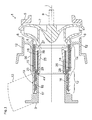
- FIG. 1 is a section of a circulating pump 1 shown as an exemplary embodiment of a water-conducting household appliance, a dishwasher in a sectional view, which is arranged downstream of a pump pot 3 of a dishwasher.
- the circulation pump 1 conveys rinsing liquid from the sump 3 to spray devices within a washing container of the dishwasher.
- the circulation pump 1 a housing 5, in which an impeller 7 is arranged rotatably about a rotation axis I.
- the impeller 7 is drivingly connected via a dashed lines indicated drive shaft 9 with an electric motor, not shown.
- an impeller chamber 4 is provided with an inlet opening 11.
- the inlet opening 11 is formed by an annular collar, which is integrally formed rotationally symmetrical to the axis of rotation I of the impeller 7 on the housing 5.
- the impeller chamber 5 passes through a radially open annular gap 6 in a circumferential flow chamber 12, which in turn opens into a pressure-side outlet 13 of the circulation pump 1, which in the Fig. 1 is shown in dashed lines.
- the circulation pump 1 has a connection piece 19 on the inlet side.
- the connecting piece 19 is in the axial direction in a connecting portion 12, in accordance with the Fig. 1 an outlet port 17 of the pump pot 3 is inserted, and divided into a designed as a vibration damping portion vibration damper 14.
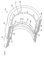
- the vibration damping portion has two opposing axial ribs 20, which connect the connecting portion 12 of the connecting piece 19 with the housing 5. The two axial ribs 20 thus bridge according to the Fig. 3 a clearance a between the connecting portion 12 and the pump housing 5.
- the connecting portion 12 of the connecting piece 19 via a hollow cylindrical sealing element 15 is liquid-tightly connected to the pump housing 5.
- the sealing element 15 according to the Fig. 1 formed on an inner peripheral wall of the annular collar 11.
- the sealing element 15 is formed in contrast to the connecting piece 19 made of an elastically flexible plastic soft component.
- the outlet nozzle 17 of the pumping pot 3 is pressed into an inner circumferential surface of the sealing element 15.
- the plastic soft component used for the production of the sealing element 15 has only a limited inherent rigidity, which is a disadvantage for a liquid-tight connection to the connecting piece 17 mounting technology. To increase the inherent rigidity, therefore, the sealing element 15 is manufactured together with the connecting piece 17 in the two-component injection molding as a structural unit.
- the connecting portion 12 of the connecting piece 17 is at a gradation 23 in a smaller diameter support ring 25 via.
- the smaller diameter support ring 25 protrudes according to the Fig. 1 in the axial direction with its front side contactless in a rotationally symmetrical suction port 27 of the impeller 7 a.
- the sealing element 15 has an inner sealing ring 16 and an outer sealing ring 18.
- the inner sealing ring 16 of the sealing member 15 is press-fitted at the connecting portion 12 of the reinforcing member 19 between the inner circumference thereof and an outer periphery of the exhaust nozzle 17.
- the outer sealing ring 18 of the sealing element 15 is disposed on the downstream support ring 25 between its outer periphery and the inner peripheral wall of the annular collar 11.
- the sealing rings 16, 18 of the sealing element 15 are integrally formed.
- the sealing rings 16, 18 are for this purpose via connecting webs 29 in conjunction, as shown in the Fig. 1 or in the Fig. 2 are shown.
- the connecting webs 29 extend through corresponding recesses 31, which according to the Fig. 3 are provided in an annular shoulder 33 of the gradation 23.
- the one-piece sealing element 15 is thus provided both on the inner circumference of the connecting portion 12 and on the outer circumference of the downstream support ring 25 of the connecting piece 19.
- the sealing element 15 is arranged between the annular collar 11 of the pump housing 1 and the smaller-diameter support ring 25 of the connecting piece 19 with suitable elasticity in order to reduce the transmission of torsional vibrations.
- the sealing element 15 according to the Fig. 1 and 2 double-walled formed with an integrally formed on the annular collar 11 outer wall 35 and an integrally formed on the smaller diameter support ring 25 inner wall 37.
- radial webs 39 are arranged between the inner and outer walls 35, 37 of the sealing element, which divide the annular gap between the inner and outer walls 35, 37 in the circumferential direction.
- the annular shoulder 33 at the step 23 of the connecting piece 19 forms during the assembly of the outlet nozzle 17 in the axial direction of a movement stop.
- the end face of the outlet nozzle 17 is not directly on the made of the hard component annular shoulder 33 of the reinforcing element 19, but with the interposition of a circumferential annular rib 41, which is drawn from the sealing nozzle 15 radially inwardly.
- the connecting piece 17 of the pump pot 3 is pressed into the sealing element 15 in the axial direction.
- the connecting piece 19 is rigidly supported on the pump housing 1 in the axial direction. This is formed the connecting piece 19 in the region of its gradation 23 with the two diametrically opposed axial ribs 20 outside of the annular collar 11 on the pump housing 5. Since the connecting portion 12 of the connecting piece 19 is connected to the pump housing 1 only via the two narrow axial ribs 20, the elastic resilience of the sealing stub 15 required for vibration damping is not unduly impaired in the tangential direction.
Landscapes
- Engineering & Computer Science (AREA)
- Water Supply & Treatment (AREA)
- Structures Of Non-Positive Displacement Pumps (AREA)
- Vibration Dampers (AREA)
Abstract
Description
- Die Erfindung betrifft ein wasserführendes Haushaltsgerät, insbesondere eine Geschirrspülmaschine, mit zwei flüssigkeitsführenden Bauteilen, wobei ein flüssigkeitsführendes Bauteil einen angeformten Anschlussstutzen aufweist, der mit dem anderen flüssigkeitsführenden Bauteil durch eine Fügebewegung in Axialrichtung des Anschlussstutzens flüssigkeitsdicht verbunden ist.
- Wasserführende Haushaltsgeräte, wie z. B. Geschirrspülmaschinen, weisen im Bodenbereich des Spülbehälters einen Pumpentopf auf, an dem eine Umwälzpumpe angeschlossen ist. Im Spülbetrieb wird die im Pumpentopf gesammelte Spülflüssigkeit von der Umwälzpumpe angesaugt und zu Sprüheinrichtungen der Geschirrspülmaschine geleitet. Zwischen dem Pumpentopf und der Umwälzpumpe ist eine Geräuschentkopplung vorgesehen. Diese verhindert eine Übertragung von betriebsbedingten Schwingungen ausgehend von der Umwälzpumpe auf den Spülbehälter. Dabei kann zur Geräuschentkopplung eine Dichtung aus einem thermoplastischen Elastomer an eine Umwälzpumpe angeformt sein, die als Anschlussstutzen zur Herstellung einer Verbindung mit einem weitern flüssigkeitsführenden Bauteil, wie z. B. einem Leitungsabschnitt dient. Zur Herstellung einer flüssigkeitsdichten Verbindung ist jedoch die Montage einer Ohrklemme oder Drahtschelle erforderlich, was den Montageaufwand erhöht.
- Es ist daher Aufgabe der Erfindung, ein wasserführendes Haushaltsgerät, insbesondere eine Geschirrspülmaschine bereitzustellen, bei der der Montageaufwand reduziert ist.
- Erfindungsgemäß ist ein Schwingungsdämpfer vorgesehen, der in Axialrichtung steif zur Durchführung der Fügebewegung ausgebildet ist und um eine Drehachse zur Aufnahme von Torsionsschwingungen zwischen den beiden Bauteilen verformbar ausgebildet ist. Der Schwingungsdämpfer kann dem Anschlussstutzen zugeordnet sein und als Schwingungsdämpfungsabschnitt des Anschlussstutzens ausgebildet sein. Der Schwingungsdämpfer ist derart steif ausgebildet, dass eine Montage durch eine Fügebewegung der beiden Bauteile möglich ist, d.h. es erfolgt keine oder lediglich eine geringfügige Verformung während der Montage. Somit ist der Schwingungsdämpfer derart steif ausgebildet, dass mindestens die Reibungskräfte überwindende Kräfte übertragen werden können, wenn die beiden Bauteile miteinander verbunden werden und die Reibungskräfte im Verbindungsbereich überwunden werden müssen. Es können auch Fehlerfälle bei der Montage berücksichtigt werden, z.B. wenn keine Gleitmittel verwendet werden oder bei einem maschinellen Fügen zu hohe Kräfte aufgebracht werden, in dem der Schwingungsdämpfer entsprechend steif ausgebildet wird. Ferner kann der Schwingungsdämpfer Abschnitte aufweisen, die weniger steif ausgebildet sind und sich während der Fügebewegung in Axialrichtung verformen, wie z.B. elastische Dichtungsabschnitte.
- Der Schwingungsdämpfer ist z.B. in Umfangsrichtung elastisch nachgiebig ausgebildet, wodurch Torsionsschwingungen gedämpft werden können und damit die Übertragung von Torsionsschwingungen von einem auf das andere Bauteil. Hierzu ist vorzugsweise vorgesehen, dass die Drehachse sich in Axialrichtung erstreckt. Dabei erstreckt sich die Axialrichtung in Durchflussrichtung durch den Anschlussstutzen und im Fall eines Anschlussstutzens mit kreisförmigem Querschnitt ist die Drehachse die Symmetrieachse des Anschlussstutzens. Auf diese Weise kann nicht nur das gummielastische Dichtelement zur flüssigkeitsdichten Verbindung zwischen angrenzenden flüssigkeitsführenden Bauteilen Motorschwingungen aufnehmen, sondern zusätzlich auch der Anschlussstutzen zumindest eines der beiden flüssigkeitsführenden Bauteile.
- Vorzugsweise ist vorgesehen, dass der Schwingungsdämpfer in Axialrichtung steifer ausgebildet ist als in Richtung der Drehachse, die sich um die Axialrichtung erstreckt. So wird eine Montage mit besonders geringen Verformungen möglich. Es ist aber auch möglich, dass der Schwingungsdämpfer in Axialrichtung weniger steif ist als um die Drehachse, wenn z.B. eine Übertragung von Torsionsschwingungen durch ein um die Drehachse relativ steifen Schwingungsdämpfer unterbunden werden kann.
- Der Schwingungsdämpfer kann vorzugsweise zwischen einem am freien Ende des Anschlussstutzens vorgesehenen Verbindungsabschnitt und dem Gehäuse des flüssigkeitsführenden Bauteils angeordnet sein. Im Montagevorgang wird der Anschlussstutzen mit seinem stirnseitigen Verbindungsabschnitt in Steckverbindung mit dem Anschlussstutzen eines angrenzenden Bauteils gebracht. Der Schwingungsdämpfer kann demgegenüber in Form von Materialschwächungen unmittelbar am Übergang zwischen dem Anschlussstutzen und dem Bauteil-Gehäuse vorgesehen werden. In einer Ausführungsform kann der Schwingungsdämpfer zumindest eine Axialrippe sein. Diese kann einen Freiraum zwischen dem Verbindungsabschnitt des Anschlussstutzens und dem Bauteil-Gehäuse überbrücken.
- Vorzugsweise ist der Verbindungsabschnitt des Anschlussstutzens über die zumindest eine Axialrippe steif am Gehäuse abgestützt. Der Anschlussstutzen bildet somit insgesamt ein in Axialrichtung starres Widerlager, wodurch angrenzende Bauteile ohne weiteres betriebssicher in Steckverbindung mit dem Anschlussstutzen gebracht werden können.
- Bevorzugt kann die Axialrippe ausreichend schmal mit geringer Materialstärke gefertigt werden. Dadurch ist vorteilhaft in Axialrichtung eine ausreichende Versteifung bereitgestellt, jedoch bleibt zur Aufnahme der Tangentialschwingungen eine ausreichende Torsionsfähigkeit erhalten. Als Varianten können die Axialrippen auch spiralförmig, bogenförmig oder gekröpft angeordnet werden, so dass nicht nur Tangentialschwingungen, sondern auch zusätzlich Axialschwingungen aufgenommen werden können.
- Wie oben erwähnt, kann der Verbindungsabschnitt des Anschlussstutzen zumindest über einen Freiraum vom Bauteil-Gehäuse beabstandet sein. Der Freiraum kann bevorzugt mittels eines Dichtelementes flüssigkeitsdicht überbrückt werden. Das Dichtelement kann daher radial innerhalb des Schwingungsdämpfers verlaufen und in flüssigkeitsdichter Verbindung mit einem Innenumfangsabschnitt einer Öffnung des Bauteil-Gehäuses sein. Dabei kann der Schwingungsdämpfer des Anschlussstutzens radial außerhalb dieser Gehäuse-Öffnung am Gehäuse angeformt sein.
- Bei der oben angegebenen Anordnung ist eine ausreichende Stabilität des sich zwischen dem Verbindungsabschnitt des Anschlussstutzens und dem Bauteil-Gehäuse erstreckenden Dichtelementes von Bedeutung. Hierzu kann sich das Dichtelement an einem Stützring abstützen. Dieser kann aus Stabilitätsgründen insbesondere am Verbindungsabschnitt des Anschlussstutzens angeformt sein.
- Bevorzugt kann sich das Dichtelement bis zum stirnseitigen Verbindungsabschnitt des Anschlussstutzens erstrecken. Auf diese Weise kann das Dichtelement einerseits denn oben erwähnten Freiraum zwischen dem Anschlussstutzen und dem Gehäuse überbrücken. Andererseits kann das Dichtelement zusätzlich auch eine flüssigkeitsdichte Steckverbindung mit dem angrenzenden flüssigkeitsführenden Bauteil gewährleisten.
- Zur weiteren Schwingungsdämpfung insbesondere von Axialschwingungen kann das Dichtelement einen radial nach innen eingezogenen Ringbund aufweisen. Dieser kann einem Bewegungsanschlag für einen Anschlussstutzen eines angrenzenden Bauteils dienen. Der Ringbund des Dichtelementes kann einer Abstufung abgestützt sein, an der der Verbindungsabschnitt des Anschlussstutzens in den oben erwähnten Stützring zur Abstützung des Dichtelementes übergeht.
- Das Dichtelement kann am Verbindungsabschnitt des Anschlussstutzens innenseitig im Anschlussstutzen angeordnet sein, während es im Schwingungsdämpfer radial außerhalb des Stützringes angeordnet ist. Dabei kann das Dichtelement durch Aussparungen geführt sein, die in der Abstufung zwischen dem Verbindungsabschnitt und dem Stützring eingearbeitet sind.
- Bevorzugt ist der Anschlussstutzen des flüssigkeitsführenden Bauteils sowie das Dichtelement aus Kunststoff gefertigt. Bevorzugt ist hierbei die Anwendung einer Zweikomponenten-Spritzgusstechnik, bei der der Anschlussstutzen aus einer Kunststoff-Hartkomponente und das Dichtelement aus einer Kunststoff-Weichkomponente gebildet ist. Die Weich-Komponente weist dabei eine Shore-Härte im Bereich von 50 bis 70 auf, während die Hartkomponente eine entsprechend größere Shore-Härte aufweist.
- Vorzugsweise ist vorgesehen, dass die Axialrippe sich in radialer Richtung mit einer Länge erstreckt, die größer als die Länge ist, in die sich die Axialrippe in Umfangsrichtung erstreckt. Somit ist die Axialrippe in radialer Richtung betrachtet, deutlich länger als breiter ausgebildet. Hierdurch wird erreicht, dass Axialrippen bereitgestellt werden, die in Axialrichtung, das heißt, in Durchflussrichtung durch den Anschlussstutzen und/oder in Montagerichtung des Anschlussstutzens steif sind, um beispielsweise eine entsprechende Montagebewegung ohne Zuhilfenahme weiterer Werkzeuge ausführen zu können und andererseits die Axialrippen in der Lage sind, Torsionsschwingungen in Umfangsrichtung aufzunehmen.
- Schließlich ist vorzugsweise vorgesehen, dass das Gehäuse als Pumpentopf einer Geschirrspülmaschine ausgebildet ist, wobei die Geschirrspülmaschine insbesondere als Haushalts-Geschirrspülmaschine ausgebildet sein kann, so dass insbesondere bei Haushaltsgeräten, wie Geschirrspülmaschinen, die im Wohnbereich aufgestellt werden, die Geräuschemission reduziert sind.
- Nachfolgend ist ein Ausführungsbeispiel der Erfindung anhand der beigefügten Figuren beschrieben.
- Es zeigen:
- Fig. 1
- in einer Schnittdarstellung eine in einer Geschirrspülmaschine eingebaute Umwälzpumpe;
- Fig. 2
- das mit einer Kunststoff-Weichkomponente hergestellte Dichtelement der Umwälzpumpe in Alleinstellung; und
- Fig. 3
- der aus einer Kunststoff-Hartkomponente hergestellte Anschlussstutzen der Umwälzpumpe.
- In der
Fig. 1 ist als Ausführungsbeispiel für ein wasserführendes Haushaltsgerät eine Geschirrspülmaschine in einer Schnittdarstellung ein Ausschnitt aus einer Umwälzpumpe 1 gezeigt, die stromab eines Pumpentopfes 3 einer Geschirrspülmaschine angeordnet ist. Die Umwälzpumpe 1 fördert Spülflüssigkeit ausgehend vom Pumpentopf 3 zu Sprüheinrichtungen innerhalb eines Spülbehälters der Geschirrspülmaschine. Hierzu weist die Umwälzpumpe 1 ein Gehäuse 5 auf, in dem ein Laufrad 7 um eine Drehachse I drehbar angeordnet ist. Das Laufrad 7 ist über eine gestrichelt angedeutete Antriebswelle 9 mit einem nicht gezeigten Elektromotor trieblich verbunden. - Im Gehäuse 5 der Umwälzpumpe 1 ist eine Laufradkammer 4 mit einer Einlassöffnung 11 vorgesehen. Die Einlassöffnung 11 ist durch einen Ringkragen ausgebildet, der rotationssymmetrisch zur Drehachse I des Laufrades 7 am Gehäuse 5 angeformt ist. Die Laufradkammer 5 geht über einen radial offenen Ringspalt 6 in eine umfangsseitige Strömungskammer 12 über, die wiederum in einen druckseitigen Auslassstutzen 13 der Umwälzpumpe 1 einmündet, der in der
Fig. 1 gestrichelt dargestellt ist. - Die Umwälzpumpe 1 weist einlassseitig einen Anschlussstutzen 19 auf. Der Anschlussstutzen 19 ist in Axialrichtung in einen Verbindungsabschnitt 12, in den gemäß der
Fig. 1 ein Auslassstutzen 17 des Pumpentopfes 3 eingesetzt ist, und in einen als Schwingungsdämpfungsabschnitt ausgebildeten Schwingungsdämpfer 14 unterteilt. Der Schwingungsdämpfungsabschnitt weist zwei einander gegenüberliegende Axialrippen 20 auf, die den Verbindungsabschnitt 12 des Anschlussstutzens 19 mit dem Gehäuse 5 verbinden. Die beiden Axialrippen 20 überbrücken somit gemäß derFig. 3 einen Freiraum a zwischen dem Verbindungsabschnitt 12 und dem Pumpengehäuse 5. - Außerdem ist der Verbindungsabschnitt 12 des Anschlussstutzens 19 über ein hohlzylindrisches Dichtelement 15 flüssigkeitsdicht mit dem Pumpengehäuse 5 verbunden. Hierzu ist das Dichtelement 15 gemäß der
Fig. 1 an einer Innenumfangswand des Ringkragens 11 angeformt. Das Dichtungselement 15 ist im Unterschied zum Anschlussstutzen 19 aus einer elastisch nachgiebigen Kunststoff-Weichkomponente gebildet. An einem stromaufwärtigen Ende des Dichtelements 15 ist der Auslassstutzen 17 des Pumpentopfes 3 in eine Innenmantelfläche des Dichtelements 15 eingepresst. - Die zur Herstellung des Dichtelements 15 verwendete Kunststoff-Weichkomponente weist nur eine eingeschränkte Eigensteifigkeit auf, was für eine flüssigkeitsdichte Anbindung an den Anschlussstutzen 17 montagetechnisch von Nachteil ist. Zur Steigerung der Eigensteifigkeit ist daher das Dichtelement 15 zusammen mit dem Anschlussstutzen 17 in der Zwei-Komponenten-Spritzgusstechnik als eine Baueinheit hergestellt.
- Wie aus der
Fig. 1 in Verbindung mit derFig. 3 hervorgeht, geht der Verbindungsabschnitt 12 des Anschlussstutzens 17 an einer Abstufung 23 in einen durchmesserkleineren Stützring 25 über. Der durchmesserkleinere Stützring 25 ragt gemäß derFig. 1 in Axialrichtung mit seiner Stirnseite berührungsfrei in eine rotationssymmetrische Ansaugöffnung 27 des Laufrades 7 ein. - Wie aus der
Fig. 1 weiter hervorgeht, weist das Dichtelement 15 einen innenliegenden Dichtring 16 und einen außenliegenden Dichtring 18 auf. Der innenliegende Dichtring 16 des Dichtelements 15 ist am Verbindungsabschnitt 12 des Verstärkungselements 19 zwischen dessen Innenumfang und einem Außenumfang des Auslassstutzens 17 eingepresst. Demgegenüber ist der außenliegende Dichtring 18 des Dichtelements 15 am stromabwärtigen Stützring 25 zwischen dessen Außenumfang und der Innenumfangswand des Ringkragens 11 angeordnet. - Die Dichtringe 16, 18 des Dichtelements 15 sind einstückig ausgebildet. Die Dichtungsringe 16, 18 sind hierzu über Verbindungsstege 29 in Verbindung, wie sie in der
Fig. 1 oder in derFig. 2 gezeigt sind. Die Verbindungsstege 29 erstrecken sich durch entsprechende Aussparungen 31, die gemäß derFig. 3 in einer Ringschulter 33 der Abstufung 23 vorgesehen sind. Das einteilig gebildete Dichtelement 15 ist somit sowohl am Innenumfang des Verbindungsabschnittes 12 als auch am Außenumfang des stromabwärtigen Stützringes 25 des Anschlussstutzens 19 vorgesehen. - Das Dichtelement 15 ist zwischen dem Ringkragen 11 des Pumpengehäuses 1 und dem durchmesserkleineren Stützring 25 des Anschlussstutzens 19 mit geeigneter Elastizität angeordnet, um die Übertragung von Torsionsschwingungen zu reduzieren. Zur Einstellung der Elastizität speziell am Stützring 25 ist das Dichtelement 15 gemäß den
Fig. 1 und2 doppelwandig mit einer am Ringkragen 11 angeformten Außenwand 35 sowie einer am durchmesserkleineren Stützring 25 angeformten Innenwand 37 ausgebildet. Für eine ausreichende Steifigkeit in der Radialrichtung sind zwischen den Innen- und Außenwänden 35, 37 des Dichtelement 15 Radialstege 39 angeordnet, die den Ringspalt zwischen den Innen- und Außenwänden 35, 37 in der Umfangsrichtung unterteilen. - Die Ringschulter 33 an der Abstufung 23 des Anschlussstutzens 19 bildet bei der Montage des Auslassstutzens 17 in der Axialrichtung einen Bewegungsanschlag. Dabei liegt die Stirnseite des Auslassstutzens 17 nicht unmittelbar auf der aus der Hartkomponente gefertigten Ringschulter 33 des Verstärkungselementes 19, sondern unter Zwischenschaltung eines umlaufenden Ringsteges 41, der vom Dichtungsstutzen 15 radial nach innen eingezogen ist.
- Beim Zusammenbau wird der Anschlussstutzen 17 des Pumpentopfes 3 in Axialrichtung in das Dichtelement 15 eingepresst. Um den Einpressvorgang zu vereinfachen, ist der Anschlussstutzen 19 in Axialrichtung steif am Pumpengehäuse 1 abgestützt. Hierzu ist der Anschlussstutzen 19 im Bereich seiner Abstufung 23 mit den beiden diametral gegenüberliegenden Axialrippen 20 außerhalb des Ringkragens 11 am Pumpengehäuse 5 angeformt. Da der Verbindungsabschnitt 12 des Anschlussstutzens 19 nur über die beiden schmalen Axialrippen 20 am Pumpengehäuse 1 angebunden ist, wird die zur Schwingungsdämpfung erforderliche elastische Nachgiebigkeit des Dichtungsstutzens 15 in der Tangentialrichtung nicht übermäßig beeinträchtigt.
-
- 1
- Umwälzpumpe
- 3
- Pumpentopf
- 5
- Gehäuse
- 7
- Laufrad
- 9
- Antriebswelle
- 11
- Pumpeneinlass
- 12
- Verbindungsabschnitt
- 13
- Druckstutzen
- 14
- Schwingungsdämpfer
- 15
- Dichtelement
- 16
- innerer Dichtring
- 17
- Anschlussstutzen
- 18
- äußerer Dichtring
- 19
- Verstärkungselement
- 20
- Axialrippen
- 23
- Abstufung
- 25
- Stützring
- 27
- Einlassöffnung
- 29
- Verbindungsstege
- 31
- Aussparungen
- 33
- Ringschulter
- 35
- Außenwand
- 37
- Innenwand
- 39
- Ringspalt
- 41
- Ringsteg
- I
- Drehachse
- a
- Freiraum
Claims (17)
- Wasserführendes Haushaltsgerät, insbesondere Geschirrspülmaschine, mit zwei flüssigkeitsführenden Bauteilen (1, 3), wobei ein flüssigkeitsführendes Bauteil (1) einen angeformten Anschlussstutzen (17) aufweist, der mit dem anderen flüssigkeitsführenen Bauteil (3) durch eine Fügebewegung in Axialrichtung (I) des Anschlussstutzens (17) flüssigkeitsdicht verbunden ist, dadurch gekennzeichnet, dass ein Schwingungsdämpfer (14) vorgesehen ist, der in Axialrichtung (I) steif zur Durchführung der Fügebewegung ausgebildet ist und zur Aufnahme von Torsionsschwingungen zwischen den beiden flüssigkeitsführenden Bauteilen (1, 3) um eine Drehachse verformbar ist.
- Wasserführendes Haushaltsgerät nach Anspruch 1, dadurch gekennzeichnet, dass die Drehachse sich in Axialrichtung (I) erstreckt.
- Wasserführendes Haushaltsgerät nach Anspruch 2, dadurch gekennzeichnet, dass der Schwingungsdämpfer (14) in Axialrichtung (I) steifer ausgebildet ist als in Richtung der Drehachse, die sich um die Axialrichtung (I) erstreckt.
- Wasserführendes Haushaltsgerät nach Anspruch 1, 2 oder 3, dadurch gekennzeichnet, dass das flüssigkeitsführende Bauteil (1) in Axialrichtung (I) hintereinander angeordnet einen den Anschlußstutzen (17) zugeordneten Verbindungsabschnitt (12) zum Verbinden mit dem anderen flüssigkeitsführenden Bauteil (3), den Schwingungsdämpfer (14) und ein Gehäuse (5) umfasst.
- Wasserführendes Haushaltsgerät nach Anspruch 4, dadurch gekennzeichnet, dass der Schwingungsdämpfer (14) zumindest eine sich in Axialrichtung (I) erstreckende Axialrippe (20) ist, die einen Freiraum (a) zwischen dem Verbindungsabschnitt (12) und dem Gehäuse (5) des flüssigkeitsführenden Bauteils (1) überbrückt.
- Wasserführendes Haushaltsgerät nach Anspruch 4 oder 5, dadurch gekennzeichnet, dass ein Dichtelement (15) zwischen dem Verbindungsabschnitt (12) des Anschlussstutzens (17) und dem Gehäuse (5) des flüssigkeitsführenden Bauteils (1) angeordnet ist.
- Wasserführendes Haushaltsgerät nach Anspruch 6, dadurch gekennzeichnet, dass das Dichtelement (15) radial innerhalb des Schwingungsdämpfers (14) des Anschlussstutzens (17) angeordnet ist.
- Wasserführendes Haushaltsgerät nach Anspruch 6 oder 7, dadurch gekennzeichnet, dass das Dichtelement (15) eine fluiddichte Verbindung mit einer Innenumfangsfläche einer Öffnung (11) des Gehäuses (5) bildet.
- Wasserführendes Haushaltsgerät nach Anspruch 6, 7 oder 8, dadurch gekennzeichnet, dass der Schwingungsdämpfer (14) radial außerhalb der Gehäuseöffnung (11) am Gehäuse (5) angeformt ist.
- Wasserführendes Haushaltsgerät nach einem der Ansprüche 6 bis 9, dadurch gekennzeichnet, dass das Dichtelement (15) sich zwischen dem Verbindungsabschnitt (12) des Anschlussstutzens (17) und dem Gehäuse (5) erstreckt, insbesondere bis zum Verbindungsabschnitt (12) des Anschlussstutzens (17) erstreckt.
- Wasserführendes Haushaltsgerät nach einem der Ansprüche 6 bis 10, dadurch gekennzeichnet, dass das Dichtelement (15) an einem Stützring (25) abgestützt ist.
- Wasserführendes Haushaltsgerät nach Anspruch 11, dadurch gekennzeichnet, dass der Stützring (25) am Verbindungsabschnitt (12) des Anschlussstutzens (17) angeformt ist.
- Wasserführendes Haushaltsgerät nach einem der Ansprüche 6 bis 11, dadurch gekennzeichnet, dass das Dichtelement (15) einen Ringbund (41) zur Ausbildung eines Bewegungsanschlags für den Anschlussstutzen (17) des angrenzenden flüssigkeitsführenden Bauteils (3) aufweist.
- Wasserführendes Haushaltsgerät nach Anspruch 12 oder 13, dadurch gekennzeichnet, dass das Dichtelement (15) am Verbindungsabschnitt (12) des Anschlussstutzens (17) innenseitig im Anschlussstutzen (17) angeordnet ist.
- Wasserführendes Haushaltsgerät nach einem der vorhergehenden Ansprüche, dadurch gekennzeichnet, dass der Anschlussstutzen (17) aus einer Kunststoff-Hartkomponente und/oder das Dichtelement (15) aus einer Kunststoff-Weichkomponente gebildet ist, wobei insbesondere die Kunststoff-Weichkomponente eine Shore-Härte im Bereich von 50 bis 70 aufweist und die Kunststoff-Hartkomponente eine Shore-Härte von mehr als 70 aufweist.
- Wasserführendes Haushaltsgerät nach einem der Ansprüche 5 bis 15, dadurch gekennzeichnet, dass die Axialrippe (20) sich in radialer Richtung mit einer Länge erstreckt, die größer als die Länge ist, in die sich die Axialrippe (20) in Umfangsrichtung erstreckt.
- Wasserführendes Haushaltsgerät nach einem der Ansprüche 4 bis 16, dadurch gekennzeichnet, dass das Gehäuse (5) als Pumpentopf einer Geschirrspülmaschine ausgebildet ist.
Priority Applications (1)
| Application Number | Priority Date | Filing Date | Title |
|---|---|---|---|
| PL11179160T PL2430968T3 (pl) | 2010-09-14 | 2011-08-29 | Prowadzące wodę urządzenie gospodarstwa domowego, zwłaszcza zmywarki do naczyń |
Applications Claiming Priority (1)
| Application Number | Priority Date | Filing Date | Title |
|---|---|---|---|
| DE102010040691A DE102010040691A1 (de) | 2010-09-14 | 2010-09-14 | Wasserführendes Haushaltsgerät, insbesondere Geschirrspülmaschinen |
Publications (3)
| Publication Number | Publication Date |
|---|---|
| EP2430968A2 true EP2430968A2 (de) | 2012-03-21 |
| EP2430968A3 EP2430968A3 (de) | 2018-01-03 |
| EP2430968B1 EP2430968B1 (de) | 2019-07-17 |
Family
ID=44936157
Family Applications (1)
| Application Number | Title | Priority Date | Filing Date |
|---|---|---|---|
| EP11179160.4A Active EP2430968B1 (de) | 2010-09-14 | 2011-08-29 | Wasserführendes Haushaltsgerät, insbesondere Geschirrspülmaschinen |
Country Status (3)
| Country | Link |
|---|---|
| EP (1) | EP2430968B1 (de) |
| DE (1) | DE102010040691A1 (de) |
| PL (1) | PL2430968T3 (de) |
Cited By (2)
| Publication number | Priority date | Publication date | Assignee | Title |
|---|---|---|---|---|
| US10064537B2 (en) | 2014-11-24 | 2018-09-04 | Whirlpool Corporation | Dishwasher drain assemblies having overmolded volutes |
| EP4130489A1 (de) | 2021-08-03 | 2023-02-08 | Bleckmann GmbH & Co. KG | Druckhülse für eine flüssigkeitspumpe und pumpe mit der druckhülse |
Family Cites Families (5)
| Publication number | Priority date | Publication date | Assignee | Title |
|---|---|---|---|---|
| JPH0420319A (ja) * | 1990-05-14 | 1992-01-23 | Matsushita Electric Ind Co Ltd | 食器洗い機 |
| KR100457597B1 (ko) * | 2003-01-06 | 2004-11-17 | 엘지전자 주식회사 | 식기세척기의 필터장치 |
| EP1681007B1 (de) * | 2005-01-17 | 2008-04-02 | Askoll Holding S.r.l. | Kupplungsmanschette für die hydraulische Verbindung einer elektrischen Pumpe mit dem Laugenbehälter einer Waschmaschine |
| EP1974086B1 (de) * | 2005-12-30 | 2009-03-11 | Arcelik Anonim Sirketi | Waschvorrichtung |
| US8297660B2 (en) * | 2007-07-07 | 2012-10-30 | Electrolux Home Products Corporation N.V. | Water-conducting household appliance |
-
2010
- 2010-09-14 DE DE102010040691A patent/DE102010040691A1/de not_active Withdrawn
-
2011
- 2011-08-29 EP EP11179160.4A patent/EP2430968B1/de active Active
- 2011-08-29 PL PL11179160T patent/PL2430968T3/pl unknown
Non-Patent Citations (1)
| Title |
|---|
| None |
Cited By (4)
| Publication number | Priority date | Publication date | Assignee | Title |
|---|---|---|---|---|
| US10064537B2 (en) | 2014-11-24 | 2018-09-04 | Whirlpool Corporation | Dishwasher drain assemblies having overmolded volutes |
| US10799084B2 (en) | 2014-11-24 | 2020-10-13 | Whirlpool Corporation | Dishwasher drain assemblies having overmolded volutes |
| EP4130489A1 (de) | 2021-08-03 | 2023-02-08 | Bleckmann GmbH & Co. KG | Druckhülse für eine flüssigkeitspumpe und pumpe mit der druckhülse |
| WO2023012218A1 (en) | 2021-08-03 | 2023-02-09 | Bleckmann Gmbh & Co. Kg | Pressure bushing for a fluid pump and a pump including the pressure bushing |
Also Published As
| Publication number | Publication date |
|---|---|
| DE102010040691A1 (de) | 2012-03-15 |
| EP2430968A3 (de) | 2018-01-03 |
| PL2430968T3 (pl) | 2020-03-31 |
| EP2430968B1 (de) | 2019-07-17 |
Similar Documents
| Publication | Publication Date | Title |
|---|---|---|
| DE19758249C2 (de) | Pumpenanschlussvorrichtung | |
| EP1777416B1 (de) | Pumpe mit integriertem Motor | |
| WO2010066540A1 (de) | Flügelrad für einen ventilator | |
| EP2191138A1 (de) | Pumpenrotor für eine spaltrohrpumpe | |
| EP2510861B1 (de) | Motoranordnung für ein elektromotorisch angetriebenes Haushaltsgerät | |
| EP2162044B1 (de) | Wasserführendes haushaltsgerät | |
| EP2430968B1 (de) | Wasserführendes Haushaltsgerät, insbesondere Geschirrspülmaschinen | |
| EP2017479A2 (de) | Befestigung eins Radiallagers im Spalttopf | |
| EP2546525B1 (de) | Kreiselpumpe mit Spiralgehäuse | |
| EP1126180A2 (de) | Pumpenlaufrad für eine in Geschirrspülmaschinen einsetzbare Umwälzpumpe | |
| EP3414460B1 (de) | Wäschepflegegerät mit einem dichtelement | |
| DE102005036818B4 (de) | Pumpengehäuse, Pumpe und wasserführendes Haushaltsgerät | |
| DE602005005778T2 (de) | Kupplungsmanschette für die hydraulische Verbindung einer elektrischen Pumpe mit dem Laugenbehälter einer Waschmaschine | |
| EP3312429B1 (de) | Umwälzpumpe für eine geschirrspülmaschine | |
| EP2233744B1 (de) | Kreiselmotorpumpe | |
| EP0854307B1 (de) | Abdichtvorrichtung zwischen einem Laufrad und einem Gehäuse einer Pumpe mit einer Gleitringdichtung | |
| WO2014095102A1 (de) | Wasserführendes haushaltsgerät mit einer spaltrohrpumpe | |
| DE102013220689A1 (de) | Wasserführendes Haushaltsgerät | |
| WO2010006364A1 (en) | A sealing member for providing sealing between components of a rotary machine | |
| DE102008055613A1 (de) | Kreiselmotorpumpe | |
| EP3513055B1 (de) | Filtergehäuse aus kunststoff und filtersystem | |
| DE102004013034B4 (de) | Vorrichtung zum Anschluss einer Umwälzpumpe an einen Sammeltopf eines Haushaltgerätes wie einer Geschirrspüllmaschine | |
| DE29712762U1 (de) | Eingangsfilter für eine Flüssigkeitspumpe, insbesondere für Waschmaschinen | |
| DE102011011256A1 (de) | Wischwasserführende Lagerung für den Wischarm einer Scheibenwischeranordnung | |
| DE202009008204U1 (de) | Spaltrohrmotor für Kreiselpumpen |
Legal Events
| Date | Code | Title | Description |
|---|---|---|---|
| PUAI | Public reference made under article 153(3) epc to a published international application that has entered the european phase |
Free format text: ORIGINAL CODE: 0009012 |
|
| AK | Designated contracting states |
Kind code of ref document: A2 Designated state(s): AL AT BE BG CH CY CZ DE DK EE ES FI FR GB GR HR HU IE IS IT LI LT LU LV MC MK MT NL NO PL PT RO RS SE SI SK SM TR |
|
| AX | Request for extension of the european patent |
Extension state: BA ME |
|
| RAP1 | Party data changed (applicant data changed or rights of an application transferred) |
Owner name: BSH HAUSGERAETE GMBH |
|
| PUAL | Search report despatched |
Free format text: ORIGINAL CODE: 0009013 |
|
| AK | Designated contracting states |
Kind code of ref document: A3 Designated state(s): AL AT BE BG CH CY CZ DE DK EE ES FI FR GB GR HR HU IE IS IT LI LT LU LV MC MK MT NL NO PL PT RO RS SE SI SK SM TR |
|
| AX | Request for extension of the european patent |
Extension state: BA ME |
|
| RIC1 | Information provided on ipc code assigned before grant |
Ipc: A47L 15/42 20060101AFI20171129BHEP |
|
| STAA | Information on the status of an ep patent application or granted ep patent |
Free format text: STATUS: REQUEST FOR EXAMINATION WAS MADE |
|
| 17P | Request for examination filed |
Effective date: 20180703 |
|
| RBV | Designated contracting states (corrected) |
Designated state(s): AL AT BE BG CH CY CZ DE DK EE ES FI FR GB GR HR HU IE IS IT LI LT LU LV MC MK MT NL NO PL PT RO RS SE SI SK SM TR |
|
| GRAP | Despatch of communication of intention to grant a patent |
Free format text: ORIGINAL CODE: EPIDOSNIGR1 |
|
| STAA | Information on the status of an ep patent application or granted ep patent |
Free format text: STATUS: GRANT OF PATENT IS INTENDED |
|
| INTG | Intention to grant announced |
Effective date: 20190227 |
|
| GRAS | Grant fee paid |
Free format text: ORIGINAL CODE: EPIDOSNIGR3 |
|
| GRAA | (expected) grant |
Free format text: ORIGINAL CODE: 0009210 |
|
| STAA | Information on the status of an ep patent application or granted ep patent |
Free format text: STATUS: THE PATENT HAS BEEN GRANTED |
|
| AK | Designated contracting states |
Kind code of ref document: B1 Designated state(s): AL AT BE BG CH CY CZ DE DK EE ES FI FR GB GR HR HU IE IS IT LI LT LU LV MC MK MT NL NO PL PT RO RS SE SI SK SM TR |
|
| REG | Reference to a national code |
Ref country code: GB Ref legal event code: FG4D Free format text: NOT ENGLISH |
|
| REG | Reference to a national code |
Ref country code: CH Ref legal event code: EP |
|
| REG | Reference to a national code |
Ref country code: DE Ref legal event code: R096 Ref document number: 502011015905 Country of ref document: DE |
|
| REG | Reference to a national code |
Ref country code: IE Ref legal event code: FG4D Free format text: LANGUAGE OF EP DOCUMENT: GERMAN |
|
| REG | Reference to a national code |
Ref country code: AT Ref legal event code: REF Ref document number: 1155058 Country of ref document: AT Kind code of ref document: T Effective date: 20190815 |
|
| REG | Reference to a national code |
Ref country code: NL Ref legal event code: MP Effective date: 20190717 |
|
| REG | Reference to a national code |
Ref country code: LT Ref legal event code: MG4D |
|
| PG25 | Lapsed in a contracting state [announced via postgrant information from national office to epo] |
Ref country code: HR Free format text: LAPSE BECAUSE OF FAILURE TO SUBMIT A TRANSLATION OF THE DESCRIPTION OR TO PAY THE FEE WITHIN THE PRESCRIBED TIME-LIMIT Effective date: 20190717 Ref country code: LT Free format text: LAPSE BECAUSE OF FAILURE TO SUBMIT A TRANSLATION OF THE DESCRIPTION OR TO PAY THE FEE WITHIN THE PRESCRIBED TIME-LIMIT Effective date: 20190717 Ref country code: NO Free format text: LAPSE BECAUSE OF FAILURE TO SUBMIT A TRANSLATION OF THE DESCRIPTION OR TO PAY THE FEE WITHIN THE PRESCRIBED TIME-LIMIT Effective date: 20191017 Ref country code: NL Free format text: LAPSE BECAUSE OF FAILURE TO SUBMIT A TRANSLATION OF THE DESCRIPTION OR TO PAY THE FEE WITHIN THE PRESCRIBED TIME-LIMIT Effective date: 20190717 Ref country code: BG Free format text: LAPSE BECAUSE OF FAILURE TO SUBMIT A TRANSLATION OF THE DESCRIPTION OR TO PAY THE FEE WITHIN THE PRESCRIBED TIME-LIMIT Effective date: 20191017 Ref country code: PT Free format text: LAPSE BECAUSE OF FAILURE TO SUBMIT A TRANSLATION OF THE DESCRIPTION OR TO PAY THE FEE WITHIN THE PRESCRIBED TIME-LIMIT Effective date: 20191118 Ref country code: FI Free format text: LAPSE BECAUSE OF FAILURE TO SUBMIT A TRANSLATION OF THE DESCRIPTION OR TO PAY THE FEE WITHIN THE PRESCRIBED TIME-LIMIT Effective date: 20190717 Ref country code: SE Free format text: LAPSE BECAUSE OF FAILURE TO SUBMIT A TRANSLATION OF THE DESCRIPTION OR TO PAY THE FEE WITHIN THE PRESCRIBED TIME-LIMIT Effective date: 20190717 |
|
| PG25 | Lapsed in a contracting state [announced via postgrant information from national office to epo] |
Ref country code: IS Free format text: LAPSE BECAUSE OF FAILURE TO SUBMIT A TRANSLATION OF THE DESCRIPTION OR TO PAY THE FEE WITHIN THE PRESCRIBED TIME-LIMIT Effective date: 20191117 Ref country code: RS Free format text: LAPSE BECAUSE OF FAILURE TO SUBMIT A TRANSLATION OF THE DESCRIPTION OR TO PAY THE FEE WITHIN THE PRESCRIBED TIME-LIMIT Effective date: 20190717 Ref country code: LV Free format text: LAPSE BECAUSE OF FAILURE TO SUBMIT A TRANSLATION OF THE DESCRIPTION OR TO PAY THE FEE WITHIN THE PRESCRIBED TIME-LIMIT Effective date: 20190717 Ref country code: GR Free format text: LAPSE BECAUSE OF FAILURE TO SUBMIT A TRANSLATION OF THE DESCRIPTION OR TO PAY THE FEE WITHIN THE PRESCRIBED TIME-LIMIT Effective date: 20191018 Ref country code: ES Free format text: LAPSE BECAUSE OF FAILURE TO SUBMIT A TRANSLATION OF THE DESCRIPTION OR TO PAY THE FEE WITHIN THE PRESCRIBED TIME-LIMIT Effective date: 20190717 Ref country code: AL Free format text: LAPSE BECAUSE OF FAILURE TO SUBMIT A TRANSLATION OF THE DESCRIPTION OR TO PAY THE FEE WITHIN THE PRESCRIBED TIME-LIMIT Effective date: 20190717 |
|
| PG25 | Lapsed in a contracting state [announced via postgrant information from national office to epo] |
Ref country code: EE Free format text: LAPSE BECAUSE OF FAILURE TO SUBMIT A TRANSLATION OF THE DESCRIPTION OR TO PAY THE FEE WITHIN THE PRESCRIBED TIME-LIMIT Effective date: 20190717 Ref country code: DK Free format text: LAPSE BECAUSE OF FAILURE TO SUBMIT A TRANSLATION OF THE DESCRIPTION OR TO PAY THE FEE WITHIN THE PRESCRIBED TIME-LIMIT Effective date: 20190717 Ref country code: IT Free format text: LAPSE BECAUSE OF FAILURE TO SUBMIT A TRANSLATION OF THE DESCRIPTION OR TO PAY THE FEE WITHIN THE PRESCRIBED TIME-LIMIT Effective date: 20190717 Ref country code: RO Free format text: LAPSE BECAUSE OF FAILURE TO SUBMIT A TRANSLATION OF THE DESCRIPTION OR TO PAY THE FEE WITHIN THE PRESCRIBED TIME-LIMIT Effective date: 20190717 |
|
| PG25 | Lapsed in a contracting state [announced via postgrant information from national office to epo] |
Ref country code: LU Free format text: LAPSE BECAUSE OF NON-PAYMENT OF DUE FEES Effective date: 20190829 Ref country code: MC Free format text: LAPSE BECAUSE OF FAILURE TO SUBMIT A TRANSLATION OF THE DESCRIPTION OR TO PAY THE FEE WITHIN THE PRESCRIBED TIME-LIMIT Effective date: 20190717 Ref country code: SK Free format text: LAPSE BECAUSE OF FAILURE TO SUBMIT A TRANSLATION OF THE DESCRIPTION OR TO PAY THE FEE WITHIN THE PRESCRIBED TIME-LIMIT Effective date: 20190717 Ref country code: CZ Free format text: LAPSE BECAUSE OF FAILURE TO SUBMIT A TRANSLATION OF THE DESCRIPTION OR TO PAY THE FEE WITHIN THE PRESCRIBED TIME-LIMIT Effective date: 20190717 Ref country code: LI Free format text: LAPSE BECAUSE OF NON-PAYMENT OF DUE FEES Effective date: 20190831 Ref country code: SM Free format text: LAPSE BECAUSE OF FAILURE TO SUBMIT A TRANSLATION OF THE DESCRIPTION OR TO PAY THE FEE WITHIN THE PRESCRIBED TIME-LIMIT Effective date: 20190717 Ref country code: IS Free format text: LAPSE BECAUSE OF FAILURE TO SUBMIT A TRANSLATION OF THE DESCRIPTION OR TO PAY THE FEE WITHIN THE PRESCRIBED TIME-LIMIT Effective date: 20200224 Ref country code: CH Free format text: LAPSE BECAUSE OF NON-PAYMENT OF DUE FEES Effective date: 20190831 |
|
| REG | Reference to a national code |
Ref country code: BE Ref legal event code: MM Effective date: 20190831 |
|
| REG | Reference to a national code |
Ref country code: DE Ref legal event code: R097 Ref document number: 502011015905 Country of ref document: DE |
|
| PLBE | No opposition filed within time limit |
Free format text: ORIGINAL CODE: 0009261 |
|
| STAA | Information on the status of an ep patent application or granted ep patent |
Free format text: STATUS: NO OPPOSITION FILED WITHIN TIME LIMIT |
|
| PG2D | Information on lapse in contracting state deleted |
Ref country code: IS |
|
| PG25 | Lapsed in a contracting state [announced via postgrant information from national office to epo] |
Ref country code: IE Free format text: LAPSE BECAUSE OF NON-PAYMENT OF DUE FEES Effective date: 20190829 |
|
| 26N | No opposition filed |
Effective date: 20200603 |
|
| PG25 | Lapsed in a contracting state [announced via postgrant information from national office to epo] |
Ref country code: SI Free format text: LAPSE BECAUSE OF FAILURE TO SUBMIT A TRANSLATION OF THE DESCRIPTION OR TO PAY THE FEE WITHIN THE PRESCRIBED TIME-LIMIT Effective date: 20190717 Ref country code: BE Free format text: LAPSE BECAUSE OF NON-PAYMENT OF DUE FEES Effective date: 20190831 |
|
| GBPC | Gb: european patent ceased through non-payment of renewal fee |
Effective date: 20191017 |
|
| REG | Reference to a national code |
Ref country code: AT Ref legal event code: MM01 Ref document number: 1155058 Country of ref document: AT Kind code of ref document: T Effective date: 20190829 |
|
| PG25 | Lapsed in a contracting state [announced via postgrant information from national office to epo] |
Ref country code: GB Free format text: LAPSE BECAUSE OF NON-PAYMENT OF DUE FEES Effective date: 20191017 Ref country code: FR Free format text: LAPSE BECAUSE OF NON-PAYMENT OF DUE FEES Effective date: 20190917 |
|
| PG25 | Lapsed in a contracting state [announced via postgrant information from national office to epo] |
Ref country code: AT Free format text: LAPSE BECAUSE OF NON-PAYMENT OF DUE FEES Effective date: 20190829 |
|
| PG25 | Lapsed in a contracting state [announced via postgrant information from national office to epo] |
Ref country code: CY Free format text: LAPSE BECAUSE OF FAILURE TO SUBMIT A TRANSLATION OF THE DESCRIPTION OR TO PAY THE FEE WITHIN THE PRESCRIBED TIME-LIMIT Effective date: 20190717 |
|
| PG25 | Lapsed in a contracting state [announced via postgrant information from national office to epo] |
Ref country code: HU Free format text: LAPSE BECAUSE OF FAILURE TO SUBMIT A TRANSLATION OF THE DESCRIPTION OR TO PAY THE FEE WITHIN THE PRESCRIBED TIME-LIMIT; INVALID AB INITIO Effective date: 20110829 Ref country code: MT Free format text: LAPSE BECAUSE OF FAILURE TO SUBMIT A TRANSLATION OF THE DESCRIPTION OR TO PAY THE FEE WITHIN THE PRESCRIBED TIME-LIMIT Effective date: 20190717 |
|
| PG25 | Lapsed in a contracting state [announced via postgrant information from national office to epo] |
Ref country code: MK Free format text: LAPSE BECAUSE OF FAILURE TO SUBMIT A TRANSLATION OF THE DESCRIPTION OR TO PAY THE FEE WITHIN THE PRESCRIBED TIME-LIMIT Effective date: 20190717 |
|
| PGFP | Annual fee paid to national office [announced via postgrant information from national office to epo] |
Ref country code: DE Payment date: 20250831 Year of fee payment: 15 |
|
| PGFP | Annual fee paid to national office [announced via postgrant information from national office to epo] |
Ref country code: TR Payment date: 20250821 Year of fee payment: 15 Ref country code: PL Payment date: 20250822 Year of fee payment: 15 |