EP2430933A1 - Ski jumping boot and binding system comprising a jumping boot and a ski binding - Google Patents
Ski jumping boot and binding system comprising a jumping boot and a ski binding Download PDFInfo
- Publication number
- EP2430933A1 EP2430933A1 EP11007668A EP11007668A EP2430933A1 EP 2430933 A1 EP2430933 A1 EP 2430933A1 EP 11007668 A EP11007668 A EP 11007668A EP 11007668 A EP11007668 A EP 11007668A EP 2430933 A1 EP2430933 A1 EP 2430933A1
- Authority
- EP
- European Patent Office
- Prior art keywords
- ski
- boot
- heel
- binding
- sole
- Prior art date
- Legal status (The legal status is an assumption and is not a legal conclusion. Google has not performed a legal analysis and makes no representation as to the accuracy of the status listed.)
- Granted
Links
- 230000027455 binding Effects 0.000 title claims abstract description 33
- 238000009739 binding Methods 0.000 title claims abstract description 33
- 230000009191 jumping Effects 0.000 title claims abstract description 17
- 244000309466 calf Species 0.000 claims description 15
- 230000014759 maintenance of location Effects 0.000 claims 1
- 230000006978 adaptation Effects 0.000 description 1
- 210000003423 ankle Anatomy 0.000 description 1
- 230000002349 favourable effect Effects 0.000 description 1
- 210000002683 foot Anatomy 0.000 description 1
- 210000004744 fore-foot Anatomy 0.000 description 1
- 230000006641 stabilisation Effects 0.000 description 1
- 238000011105 stabilization Methods 0.000 description 1
- 230000000087 stabilizing effect Effects 0.000 description 1
Images


Classifications
-
- A—HUMAN NECESSITIES
- A63—SPORTS; GAMES; AMUSEMENTS
- A63C—SKATES; SKIS; ROLLER SKATES; DESIGN OR LAYOUT OF COURTS, RINKS OR THE LIKE
- A63C9/00—Ski bindings
- A63C9/20—Non-self-releasing bindings with special sole edge holders instead of toe-straps
-
- A—HUMAN NECESSITIES
- A43—FOOTWEAR
- A43B—CHARACTERISTIC FEATURES OF FOOTWEAR; PARTS OF FOOTWEAR
- A43B5/00—Footwear for sporting purposes
- A43B5/04—Ski or like boots
- A43B5/0427—Ski or like boots characterised by type or construction details
- A43B5/0452—Adjustment of the forward inclination of the boot leg
- A43B5/0454—Adjustment of the forward inclination of the boot leg including flex control; Dampening means
- A43B5/0456—Adjustment of the forward inclination of the boot leg including flex control; Dampening means with the actuator being disposed at the rear side of the boot
-
- A—HUMAN NECESSITIES
- A43—FOOTWEAR
- A43B—CHARACTERISTIC FEATURES OF FOOTWEAR; PARTS OF FOOTWEAR
- A43B5/00—Footwear for sporting purposes
- A43B5/04—Ski or like boots
- A43B5/0427—Ski or like boots characterised by type or construction details
- A43B5/0466—Adjustment of the side inclination of the boot leg; Canting
-
- A—HUMAN NECESSITIES
- A43—FOOTWEAR
- A43B—CHARACTERISTIC FEATURES OF FOOTWEAR; PARTS OF FOOTWEAR
- A43B5/00—Footwear for sporting purposes
- A43B5/04—Ski or like boots
- A43B5/0427—Ski or like boots characterised by type or construction details
- A43B5/0468—Adjustment of the angle of the boot to the ski
-
- A—HUMAN NECESSITIES
- A43—FOOTWEAR
- A43B—CHARACTERISTIC FEATURES OF FOOTWEAR; PARTS OF FOOTWEAR
- A43B5/00—Footwear for sporting purposes
- A43B5/04—Ski or like boots
- A43B5/0496—Ski or like boots boots for touring or hiking skis
-
- A—HUMAN NECESSITIES
- A43—FOOTWEAR
- A43B—CHARACTERISTIC FEATURES OF FOOTWEAR; PARTS OF FOOTWEAR
- A43B5/00—Footwear for sporting purposes
- A43B5/04—Ski or like boots
- A43B5/0498—For ski jumping
-
- A—HUMAN NECESSITIES
- A63—SPORTS; GAMES; AMUSEMENTS
- A63C—SKATES; SKIS; ROLLER SKATES; DESIGN OR LAYOUT OF COURTS, RINKS OR THE LIKE
- A63C2201/00—Use of skates, skis, roller-skates, snowboards and courts
- A63C2201/04—Ski jumping
Definitions
- the invention relates to a ski boot for use in the ski binding with an adjustable calf spoiler, which is used in ski jumping to achieve increased safety in the approach, during the flight phase and landing. Furthermore, the invention relates to a ski binding, in particular for ski jumping or ski flying, with a front holding means for the sole of the ski boot and liftable from the ski heel holding device which connects the heel of the ski boot with the ski and allows lifting of the shoe heel to a predetermined height ,
- Ski bindings and ski jumping boots for ski jumping or ski flying are known.
- the heel-holding device has an inextensible, all-round, band-shaped tension member, which is fastened at one end to the ski and can be fixed at its other end to a pin on the boot heel by means of a clamp.
- the tension member is arbitrarily detachable and deductible when a substantially acting in the direction of the sole sole traction of a pin.
- On the tension member at a distance from each other two parts of a connecting piece are adjustably fastened. The two parts form a trained in the manner of a push button connector. In the closed state of the connector remains a loop of the tension member, which after release of the connecting piece in the action of a increased tensile force leads to an extension of the tension member, whereby the boot heel can be lifted further from the ski.
- the binding in which the boot is held at its front sole end such that the boot heel can be lifted by the ski or by a skifesten heel element has a guided around the boot heel strap or the like that ensures a secure fit of the boot.
- the tension band is connected with its two front ends at a transverse to the longitudinal direction extending, below the boot sole in the ball area of the same on the ski body or at a front part of the binding about a perpendicular to the ski deck or boot sole axis extending pivotally held lever, said comes out of engagement with the pivot axis after exceeding a predetermined angle at the exact transverse position out.
- a belt or cord-like means arranged on the ski or on the support element, which means can be connected to the rearward section of the tensioning element, limits the lifting of the boot heel from the ski or support element.
- the binding comprises a front sole holder and a liftable from the ski heel holding device having a universally movable tension member that connects the boot heel with the ski and a lifting of the boot heel allows up to a predetermined height, the tension member at this height from a predeterminable value pulling force acting on the boot heel can be extended to a greater length against the resistance of an additional device.
- the binding system comprises a clamping device which holds the sole of the ski boot in the forefoot region against longitudinal forces and transverse forces below a triggering value and a guide strap arrangement which guides along an arc along a curve by means of a spur attachment arranged on the heel region and limits the maximum angular position of the ski boot sole relative to the upper side.
- the guide bracket assembly is with stop means, in particular for the spur lug provided that limits the minimum angular position of the ski shoe sole against the top of the skis.
- the binding systems described above only regulate the angle of attack between the sole of the ski boot and the ski, but not the torsional behavior about the longitudinal axis of the ski during the flight phase.
- the disadvantage here is that the calf spoiler of the ski jumping boot is movable only in one plane. This means that the calf spoiler is free to move forward only and the movement is limited in the opposite direction by the adjusting plates. A lateral movement of the spoiler is not possible.
- the object of the invention is a ski boot and binding system comprising a jump boot and a ski binding with which it is possible on the one hand influence both the angle of attack between the sole of the ski boot and the ski and on the To take torsional behavior about the longitudinal axis of the skis, and on the other hand to provide improved ski jump boots, with which it is possible by adjusting the Wadenspoilers in two levels, ie, forward and lateral, a precise adjustment of the Wadenspoiler for the different Absprungwinkel in the foot and Achieve calf area to take a favorable aerodynamic attitude after the jump. Furthermore, the task continues to provide a combination of binding and jump boots, with a horizontal guidance of the jump skis is made possible during the flight phase.
- ski jumping boot and binding system comprising a jump boot according to claim 1 and a ski binding according to claim 4.
- Advantageous development of the subject invention are described in the subclaims.
- the invention essentially consists of a combination of a binding system mounted on a skip 2, consisting of a front support for the sole 8 and a heel-holding device 1, and a ski-jumping boot 5 which can be inserted into this binding.
- FIG. 1 shows a perspective view of the heel holder 1.
- the heel holding device 1 consists of two flexible tension members 3, which are fastened with their one end by means of a mounting plate 6 on the jump ski 2.
- the free ends of the tension members 3 are passed through the lateral portions of the connecting piece 4 and are held by corresponding clamping devices.
- the connecting piece 4 can be connected to the shoulder of the ski boot boot 5. This can be done by suitable locking elements.
- the tension members 3 are arranged approximately parallel to each other and in each case in the lateral portions of the connecting piece 4 are clamped, the tension members 3 can be set in the same or different lengths.
- the FIG. 2 This consists essentially of a shaft on which the movable cervical spine 7 is attached and a sole 8.
- the sole has in the front region 9 an approach with a transversely extending groove for attachment of the ski boot 5 in the Binding of the jumping ski 2.
- the calf spoiler 7 is connected via pivot points with the shaft so that it can perform a movement in two planes. The movement can on the one hand in the longitudinal direction ( FIG. 3 ) to the ski boot 5 and the other in the lateral direction ( FIG. 4 ) - transverse to the longitudinal direction - take place.
- a limiting device 11 we the movement - erection of the Wadenspoilers 7 - limited, while in the opposite direction, no limitation.
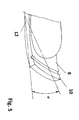
- FIG. 5 shows the front portion 9 of the sole 8 of the ski boot boot 5.
- the front portion 9 of the sole 8 is made starting from the ball area from the outside 12 to the inside 10 at an angle ⁇ . This is achieved during the flight phase that the jump skis 2 can be guided almost horizontally with respect to its longitudinal axis and tilting caused by the V-style, safely avoided.
- ski jump boots 5 and heel hold device 1 of the ski binding achieves a precise angle of attack of the jump ski 2 after the jump, an improved flying behavior and the best possible control of the jump ski 2. Furthermore, by the mobility of the Wadenspoilers 7 both forward - 1st level - as well as laterally - 2nd level - the landing safer and a telemark landing supported.
- the individually adjustable ski jumping boot 5 positively influences the safety of the skijumper in all phases of the jump.
Landscapes
- Health & Medical Sciences (AREA)
- General Health & Medical Sciences (AREA)
- Physical Education & Sports Medicine (AREA)
- Footwear And Its Accessory, Manufacturing Method And Apparatuses (AREA)
Abstract
Description
Die Erfindung betrifft einen Skisprungstiefel für den Einsatz in die Skibindung mit einem einstellbaren Wadenspoiler, der im Skisprung zur Erreichung einer erhöhten Sicherheit in der Anfahrt, während der Flugphase sowie bei der Landung Anwendung findet. Ferner betrifft die Erfindung eine Skibindung, insbesondere für das Skispringen oder Skifliegen, mit einer vorderen Halteeinrichtung für die Sohle des Skischuhs und einer vom Ski abhebbaren Fersenhalteeinrichtung, die den Absatz des Skischuhs mit dem Ski verbindet und ein Abheben des Schuhabsatzes bis zu einer vorgegebenen Höhe zuläßt.The invention relates to a ski boot for use in the ski binding with an adjustable calf spoiler, which is used in ski jumping to achieve increased safety in the approach, during the flight phase and landing. Furthermore, the invention relates to a ski binding, in particular for ski jumping or ski flying, with a front holding means for the sole of the ski boot and liftable from the ski heel holding device which connects the heel of the ski boot with the ski and allows lifting of the shoe heel to a predetermined height ,
Skibindungen und Skisprungstiefel für das Skispringen bzw. Skifliegen sind bekannt.Ski bindings and ski jumping boots for ski jumping or ski flying are known.
Aus der
Aus der
Aus der
Aus dem
Die vorbeschriebenen Bindungssysteme regeln nur den Anstellwinkel zwischen der Sohle des Skischuhs und dem Ski, aber nicht das Torsionsverhalten um die Längsachse des Sprungskis während der Flugphase.The binding systems described above only regulate the angle of attack between the sole of the ski boot and the ski, but not the torsional behavior about the longitudinal axis of the ski during the flight phase.
Aus dem
Nachteilig ist hier, daß der Wadenspoiler des Skisprungstiefels nur in einer Ebene bewegbar ist. Dies bedeutet, daß der Wadenspoiler nur nach vorne frei beweglich ist und die Bewegung in entgegengesetzter Richtung durch die Verstellplatten begrenzt ist. Eine seitliche Bewegung des Spoilers ist nicht möglich.The disadvantage here is that the calf spoiler of the ski jumping boot is movable only in one plane. This means that the calf spoiler is free to move forward only and the movement is limited in the opposite direction by the adjusting plates. A lateral movement of the spoiler is not possible.
Aufgabe der Erfindung ist es, einen Skisprungstiefel und Bindungssystem umfassend einen Sprungstiefel und eine Skibindung , mit der es einerseits möglich ist, Einfluß sowohl auf den Anstellwinkel zwischen der Sohle des Skischuhs und dem Ski als auch auf das Torsionsverhalten um die Längsachse des Sprungskis zu nehmen, und andererseits verbesserten Skisprungstiefel anzugeben, mit dem es möglich ist, durch Einstellung des Wadenspoilers in zwei Ebenen, d. h. , nach vorn und seitlich, eine genaue Einstellung des Wadenspoilers für die unterschiedlichen Absprungwinkel in den Fuß- und Wadenbereich zu erreichen, um eine vorteilhafte aerodynamische Flughaltung nach dem Absprung einzunehmen. Desweiteren besteht die Aufgabe weiterhin darin, eine Kombination aus Bindung und Sprungstiefel zu schaffen, mit der eine waagerechte Führung des Sprungski während der Flugphase ermöglicht wird.The object of the invention is a ski boot and binding system comprising a jump boot and a ski binding with which it is possible on the one hand influence both the angle of attack between the sole of the ski boot and the ski and on the To take torsional behavior about the longitudinal axis of the skis, and on the other hand to provide improved ski jump boots, with which it is possible by adjusting the Wadenspoilers in two levels, ie, forward and lateral, a precise adjustment of the Wadenspoiler for the different Absprungwinkel in the foot and Achieve calf area to take a favorable aerodynamic attitude after the jump. Furthermore, the task continues to provide a combination of binding and jump boots, with a horizontal guidance of the jump skis is made possible during the flight phase.
Die Aufgabe der Erfindung wird durch eine Kombination von Skisprungstiefel und Bindungssystem umfassend einen Sprungstiefel gemäß Anspruch 1 und eine Skibindung gemäß Anspruch 4 gelöst. Vorteilhafte Weiterbildung der Erfindungsgegenstände sind in den Unteransprüchen beschrieben.The object of the invention is achieved by a combination of ski jumping boot and binding system comprising a jump boot according to
Anhand eines Ausführungsbeispiels soll die Erfindung näher beschrieben werden. Es zeigen
-
Figur 1 - perspektivische Darstellung der Kombination Skisprungsstiefel und Bindungssystem -
Figur 2 - Seitenansicht des Skisprungstiefels -
Figur 3 - Verstellung des Wadenspoilers in Längsrichtung -
Figur 4 - Verstellung des Wadenspoilers quer zur Längsrichtung -
Figur 5 - Abschnitt der Sohle des Skisprungstiefels
-
FIG. 1 - perspective view of the combination ski boot and binding system -
FIG. 2 - Side view of ski jump boot -
FIG. 3 - Adjustment of the calf spoiler in the longitudinal direction -
FIG. 4 - Adjustment of the calf spoiler transversely to the longitudinal direction -
FIG. 5 - Section of the sole of the skijacket
Die Erfindung besteht im wesentlichen aus einer Kombination eines auf einem Sprungski 2 angebrachten Bindungssystems, bestehend aus einer vorderen Halterung für die Sohle 8 und einer Fersenhalteeinrichtung 1, und einen in diese Bindung einsetzbaren Skisprungstiefel 5.The invention essentially consists of a combination of a binding system mounted on a
Die
Dadurch daß die Zugglieder 3 in etwa parallel zueinander angeordnet sind und jeweils in den seitlichen Abschnitten des Verbindungsstücks 4 klemmbar sind, können die Zugglieder 3 in gleicher oder in unterschiedlicher Länge eingestellt werden.Characterized in that the
Da beim heutigen Skispringen bzw. Skifliegen die Sprungski 2 nicht mehr parallel zueinander sondern V-förmig geführt werden, kommt es je nach Springer zu einem mehr oder weniger Verdrehen des Sprungskis 2 um seine Längsachse. Durch die Einstellung der Zugglieder 3, die jeweils individuell in ihrer Länge einstellbar sind, kann dem entgegengewirkt werden und die Sprungski 2, trotz V-förmiger Stellung, nahezu parallel zum Hang der Sprungschanze geführt werden.Since in today's ski jumping or ski flying the
Die
Die
Insgesamt wird durch die Kombination Skisprungstiefel 5 und Fersenhalteeinrichtung 1 der Skibindung ein präziser Anstellwinkel des Sprungski 2 nach dem Absprung, ein verbessertes Flugverhalten und eine bestmögliche Kontrolle des Sprungski 2 erreicht. Ferner wird durch die Beweglichkeit des Wadenspoilers 7 sowohl nach vorne - 1. Ebene -
als auch seitlich - 2. Ebene - der Aufsprung sicherer und eine Telemarklandung unterstützt. Durch den individuell einstellbaren Skisprungstiefel 5 wir die Sicherheit des Skispringers in allen Phasen des Sprungs positiv beeinflußt.Overall, a combination of
as well as laterally - 2nd level - the landing safer and a telemark landing supported. The individually adjustable
- 1 - Fersenhalteeinrichtung1 - heel holding device
- 2 - Sprungski2 - jump ki
- 3 - Zugglied3 - tension member
- 4 - Verbindungsstück4 - connector
- 5 - Skisprungstiefel5 - ski boot
- 6 - Befestigungsplatte6 - mounting plate
- 7 - Wadenspoiler7 - calf spoilers
- 8 - Sohle8 - sole
- 9 - vorderer Bereich9 - front area
- 10 - Innenseite10 - inside
- 11 - Begrenzungseinrichtung11 - limiting device
- 12 - Außenseite12 - outside
- α - Winkelα - angle
Claims (10)
Applications Claiming Priority (2)
| Application Number | Priority Date | Filing Date | Title |
|---|---|---|---|
| DE202010013473U DE202010013473U1 (en) | 2010-09-21 | 2010-09-21 | ski binding |
| DE201120005708 DE202011005708U1 (en) | 2011-04-29 | 2011-04-29 | Ski boots |
Publications (2)
| Publication Number | Publication Date |
|---|---|
| EP2430933A1 true EP2430933A1 (en) | 2012-03-21 |
| EP2430933B1 EP2430933B1 (en) | 2019-01-23 |
Family
ID=44650912
Family Applications (1)
| Application Number | Title | Priority Date | Filing Date |
|---|---|---|---|
| EP11007668.4A Active EP2430933B1 (en) | 2010-09-21 | 2011-09-20 | Ski jumping boot and binding system comprising a jumping boot and a ski binding |
Country Status (1)
| Country | Link |
|---|---|
| EP (1) | EP2430933B1 (en) |
Cited By (3)
| Publication number | Priority date | Publication date | Assignee | Title |
|---|---|---|---|---|
| DE102013002058A1 (en) * | 2013-02-07 | 2014-08-07 | Paul Stöckl | Device for guiding the movement of the ankle of a skijumper |
| ITBO20130110A1 (en) * | 2013-03-13 | 2014-09-14 | Wamgroup Spa | DUST REMOVER DEVICE FOR AIRFLOWERS |
| DE102013103709A1 (en) * | 2013-04-12 | 2014-10-16 | Paul Stöckl | ski boot |
Citations (9)
| Publication number | Priority date | Publication date | Assignee | Title |
|---|---|---|---|---|
| DE4142391A1 (en) * | 1991-12-20 | 1993-06-24 | Silvretta Sherpas Sportartikel | Ski boot with flexible sole with front protrusion - which has semicircular transverse groove over entire sole width |
| EP0548806A2 (en) | 1991-12-20 | 1993-06-30 | silvretta-sherpas Sportartikel GmbH | Ski binding |
| DE19506384C1 (en) | 1995-02-23 | 1996-08-29 | Rottefella As | Binding for ski jumping or touring, especially skiing in Telemark style |
| DE20014500U1 (en) | 2000-08-22 | 2000-10-19 | Heumann, Sepp, 83080 Oberaudorf | Safety binding system |
| DE20013296U1 (en) | 2000-08-02 | 2001-03-01 | Raß, Volkmar, 08304 Schönheide | Ski jumping boots with adjustable calf spoiler |
| DE19960571C2 (en) | 1999-12-15 | 2002-02-28 | Win Air Sportartikel Gmbh | Ski binding, especially for ski jumping |
| DE20319072U1 (en) * | 2003-12-09 | 2004-02-19 | Adidas International Marketing B.V. | Ski-jumping boot comprises a shaft, a sole region having a heel region, a middle foot region and a front foot region, and a reinforcing element extending from the shaft into the sole region and surrounding the foot from behind and below |
| FR2847432A1 (en) * | 2002-11-27 | 2004-05-28 | Random Design | Footwear comprising articulated boots with different mechanical characteristics comprises rigid shell defining body receiving foot and second rigid shell defining ankle part connected by articulation with range of resistance characteristics |
| DE202010006102U1 (en) * | 2010-04-27 | 2010-08-19 | Heumann, Sepp | Safety binding system for jumping skis |
-
2011
- 2011-09-20 EP EP11007668.4A patent/EP2430933B1/en active Active
Patent Citations (9)
| Publication number | Priority date | Publication date | Assignee | Title |
|---|---|---|---|---|
| DE4142391A1 (en) * | 1991-12-20 | 1993-06-24 | Silvretta Sherpas Sportartikel | Ski boot with flexible sole with front protrusion - which has semicircular transverse groove over entire sole width |
| EP0548806A2 (en) | 1991-12-20 | 1993-06-30 | silvretta-sherpas Sportartikel GmbH | Ski binding |
| DE19506384C1 (en) | 1995-02-23 | 1996-08-29 | Rottefella As | Binding for ski jumping or touring, especially skiing in Telemark style |
| DE19960571C2 (en) | 1999-12-15 | 2002-02-28 | Win Air Sportartikel Gmbh | Ski binding, especially for ski jumping |
| DE20013296U1 (en) | 2000-08-02 | 2001-03-01 | Raß, Volkmar, 08304 Schönheide | Ski jumping boots with adjustable calf spoiler |
| DE20014500U1 (en) | 2000-08-22 | 2000-10-19 | Heumann, Sepp, 83080 Oberaudorf | Safety binding system |
| FR2847432A1 (en) * | 2002-11-27 | 2004-05-28 | Random Design | Footwear comprising articulated boots with different mechanical characteristics comprises rigid shell defining body receiving foot and second rigid shell defining ankle part connected by articulation with range of resistance characteristics |
| DE20319072U1 (en) * | 2003-12-09 | 2004-02-19 | Adidas International Marketing B.V. | Ski-jumping boot comprises a shaft, a sole region having a heel region, a middle foot region and a front foot region, and a reinforcing element extending from the shaft into the sole region and surrounding the foot from behind and below |
| DE202010006102U1 (en) * | 2010-04-27 | 2010-08-19 | Heumann, Sepp | Safety binding system for jumping skis |
Cited By (4)
| Publication number | Priority date | Publication date | Assignee | Title |
|---|---|---|---|---|
| DE102013002058A1 (en) * | 2013-02-07 | 2014-08-07 | Paul Stöckl | Device for guiding the movement of the ankle of a skijumper |
| EP2764785A1 (en) * | 2013-02-07 | 2014-08-13 | Paul Stoeckl | Device for guiding the movement of the ankle of a ski jumper |
| ITBO20130110A1 (en) * | 2013-03-13 | 2014-09-14 | Wamgroup Spa | DUST REMOVER DEVICE FOR AIRFLOWERS |
| DE102013103709A1 (en) * | 2013-04-12 | 2014-10-16 | Paul Stöckl | ski boot |
Also Published As
| Publication number | Publication date |
|---|---|
| EP2430933B1 (en) | 2019-01-23 |
Similar Documents
| Publication | Publication Date | Title |
|---|---|---|
| DE3153702C2 (en) | Ski binding | |
| EP0548806B1 (en) | Ski binding | |
| DE9421380U1 (en) | Snowboard binding | |
| DE2756897A1 (en) | SAFETY SKI BINDING | |
| EP2813268A1 (en) | Front automat | |
| DE2212494A1 (en) | Device for automatically returning a boot to a predetermined position on the ski | |
| DE2030749B2 (en) | Safety ski binding with a device to disengage the ski boot from the side | |
| DE4010118A1 (en) | BINDING DEVICE OF A PAIR OF SHOES OF A SKIER ON A SLIDING BOARD ON SNOW | |
| EP3345659B1 (en) | Automated heelholder device for a ski binding | |
| EP2430933B1 (en) | Ski jumping boot and binding system comprising a jumping boot and a ski binding | |
| AT401881B (en) | CONNECTING DEVICE FOR FASTENING A SKI BOOT ON A SKI | |
| DE2600858C3 (en) | Ski safety binding with a step plate releasably connected to the shoe | |
| EP4452430A1 (en) | Binding system for a ski touring binding | |
| EP0272317B1 (en) | Safety ski binding | |
| EP2821114B1 (en) | Safety ski binding system | |
| DE102012214002B4 (en) | Touring heel with auxiliary lever | |
| CH711713A2 (en) | Device for attaching a ski boot to a ski binding. | |
| EP0836869A2 (en) | Snowboard binding | |
| DE202011005708U1 (en) | Ski boots | |
| EP0113415B1 (en) | Safety binding for a touring ski | |
| DE3227232C2 (en) | Heel holder for a cross-country ski binding | |
| AT405245B (en) | Ski boot holder device, in particular for attaching a ski boot to a ski | |
| DE202010013473U1 (en) | ski binding | |
| EP4257212B1 (en) | Heel unit for a gliding board binding with mz release via cam bodies | |
| AT403994B (en) | Connecting device having a support element fixed in the installation area |
Legal Events
| Date | Code | Title | Description |
|---|---|---|---|
| PUAI | Public reference made under article 153(3) epc to a published international application that has entered the european phase |
Free format text: ORIGINAL CODE: 0009012 |
|
| AK | Designated contracting states |
Kind code of ref document: A1 Designated state(s): AL AT BE BG CH CY CZ DE DK EE ES FI FR GB GR HR HU IE IS IT LI LT LU LV MC MK MT NL NO PL PT RO RS SE SI SK SM TR |
|
| AX | Request for extension of the european patent |
Extension state: BA ME |
|
| 17P | Request for examination filed |
Effective date: 20120703 |
|
| 17Q | First examination report despatched |
Effective date: 20140603 |
|
| STAA | Information on the status of an ep patent application or granted ep patent |
Free format text: STATUS: EXAMINATION IS IN PROGRESS |
|
| GRAP | Despatch of communication of intention to grant a patent |
Free format text: ORIGINAL CODE: EPIDOSNIGR1 |
|
| STAA | Information on the status of an ep patent application or granted ep patent |
Free format text: STATUS: GRANT OF PATENT IS INTENDED |
|
| GRAS | Grant fee paid |
Free format text: ORIGINAL CODE: EPIDOSNIGR3 |
|
| GRAA | (expected) grant |
Free format text: ORIGINAL CODE: 0009210 |
|
| STAA | Information on the status of an ep patent application or granted ep patent |
Free format text: STATUS: THE PATENT HAS BEEN GRANTED |
|
| INTG | Intention to grant announced |
Effective date: 20181203 |
|
| AK | Designated contracting states |
Kind code of ref document: B1 Designated state(s): AL AT BE BG CH CY CZ DE DK EE ES FI FR GB GR HR HU IE IS IT LI LT LU LV MC MK MT NL NO PL PT RO RS SE SI SK SM TR |
|
| REG | Reference to a national code |
Ref country code: GB Ref legal event code: FG4D Free format text: NOT ENGLISH |
|
| REG | Reference to a national code |
Ref country code: CH Ref legal event code: EP |
|
| REG | Reference to a national code |
Ref country code: AT Ref legal event code: REF Ref document number: 1090778 Country of ref document: AT Kind code of ref document: T Effective date: 20190215 |
|
| REG | Reference to a national code |
Ref country code: IE Ref legal event code: FG4D Free format text: LANGUAGE OF EP DOCUMENT: GERMAN |
|
| REG | Reference to a national code |
Ref country code: DE Ref legal event code: R096 Ref document number: 502011015306 Country of ref document: DE |
|
| REG | Reference to a national code |
Ref country code: NL Ref legal event code: MP Effective date: 20190123 |
|
| PG25 | Lapsed in a contracting state [announced via postgrant information from national office to epo] |
Ref country code: NL Free format text: LAPSE BECAUSE OF FAILURE TO SUBMIT A TRANSLATION OF THE DESCRIPTION OR TO PAY THE FEE WITHIN THE PRESCRIBED TIME-LIMIT Effective date: 20190123 |
|
| PG25 | Lapsed in a contracting state [announced via postgrant information from national office to epo] |
Ref country code: PT Free format text: LAPSE BECAUSE OF FAILURE TO SUBMIT A TRANSLATION OF THE DESCRIPTION OR TO PAY THE FEE WITHIN THE PRESCRIBED TIME-LIMIT Effective date: 20190523 Ref country code: ES Free format text: LAPSE BECAUSE OF FAILURE TO SUBMIT A TRANSLATION OF THE DESCRIPTION OR TO PAY THE FEE WITHIN THE PRESCRIBED TIME-LIMIT Effective date: 20190123 Ref country code: SE Free format text: LAPSE BECAUSE OF FAILURE TO SUBMIT A TRANSLATION OF THE DESCRIPTION OR TO PAY THE FEE WITHIN THE PRESCRIBED TIME-LIMIT Effective date: 20190123 Ref country code: FI Free format text: LAPSE BECAUSE OF FAILURE TO SUBMIT A TRANSLATION OF THE DESCRIPTION OR TO PAY THE FEE WITHIN THE PRESCRIBED TIME-LIMIT Effective date: 20190123 Ref country code: NO Free format text: LAPSE BECAUSE OF FAILURE TO SUBMIT A TRANSLATION OF THE DESCRIPTION OR TO PAY THE FEE WITHIN THE PRESCRIBED TIME-LIMIT Effective date: 20190423 Ref country code: LT Free format text: LAPSE BECAUSE OF FAILURE TO SUBMIT A TRANSLATION OF THE DESCRIPTION OR TO PAY THE FEE WITHIN THE PRESCRIBED TIME-LIMIT Effective date: 20190123 Ref country code: PL Free format text: LAPSE BECAUSE OF FAILURE TO SUBMIT A TRANSLATION OF THE DESCRIPTION OR TO PAY THE FEE WITHIN THE PRESCRIBED TIME-LIMIT Effective date: 20190123 |
|
| PG25 | Lapsed in a contracting state [announced via postgrant information from national office to epo] |
Ref country code: BG Free format text: LAPSE BECAUSE OF FAILURE TO SUBMIT A TRANSLATION OF THE DESCRIPTION OR TO PAY THE FEE WITHIN THE PRESCRIBED TIME-LIMIT Effective date: 20190423 Ref country code: IS Free format text: LAPSE BECAUSE OF FAILURE TO SUBMIT A TRANSLATION OF THE DESCRIPTION OR TO PAY THE FEE WITHIN THE PRESCRIBED TIME-LIMIT Effective date: 20190523 Ref country code: GR Free format text: LAPSE BECAUSE OF FAILURE TO SUBMIT A TRANSLATION OF THE DESCRIPTION OR TO PAY THE FEE WITHIN THE PRESCRIBED TIME-LIMIT Effective date: 20190424 Ref country code: HR Free format text: LAPSE BECAUSE OF FAILURE TO SUBMIT A TRANSLATION OF THE DESCRIPTION OR TO PAY THE FEE WITHIN THE PRESCRIBED TIME-LIMIT Effective date: 20190123 Ref country code: LV Free format text: LAPSE BECAUSE OF FAILURE TO SUBMIT A TRANSLATION OF THE DESCRIPTION OR TO PAY THE FEE WITHIN THE PRESCRIBED TIME-LIMIT Effective date: 20190123 Ref country code: RS Free format text: LAPSE BECAUSE OF FAILURE TO SUBMIT A TRANSLATION OF THE DESCRIPTION OR TO PAY THE FEE WITHIN THE PRESCRIBED TIME-LIMIT Effective date: 20190123 |
|
| REG | Reference to a national code |
Ref country code: DE Ref legal event code: R097 Ref document number: 502011015306 Country of ref document: DE |
|
| PG25 | Lapsed in a contracting state [announced via postgrant information from national office to epo] |
Ref country code: CZ Free format text: LAPSE BECAUSE OF FAILURE TO SUBMIT A TRANSLATION OF THE DESCRIPTION OR TO PAY THE FEE WITHIN THE PRESCRIBED TIME-LIMIT Effective date: 20190123 Ref country code: IT Free format text: LAPSE BECAUSE OF FAILURE TO SUBMIT A TRANSLATION OF THE DESCRIPTION OR TO PAY THE FEE WITHIN THE PRESCRIBED TIME-LIMIT Effective date: 20190123 Ref country code: RO Free format text: LAPSE BECAUSE OF FAILURE TO SUBMIT A TRANSLATION OF THE DESCRIPTION OR TO PAY THE FEE WITHIN THE PRESCRIBED TIME-LIMIT Effective date: 20190123 Ref country code: DK Free format text: LAPSE BECAUSE OF FAILURE TO SUBMIT A TRANSLATION OF THE DESCRIPTION OR TO PAY THE FEE WITHIN THE PRESCRIBED TIME-LIMIT Effective date: 20190123 Ref country code: EE Free format text: LAPSE BECAUSE OF FAILURE TO SUBMIT A TRANSLATION OF THE DESCRIPTION OR TO PAY THE FEE WITHIN THE PRESCRIBED TIME-LIMIT Effective date: 20190123 Ref country code: AL Free format text: LAPSE BECAUSE OF FAILURE TO SUBMIT A TRANSLATION OF THE DESCRIPTION OR TO PAY THE FEE WITHIN THE PRESCRIBED TIME-LIMIT Effective date: 20190123 Ref country code: SK Free format text: LAPSE BECAUSE OF FAILURE TO SUBMIT A TRANSLATION OF THE DESCRIPTION OR TO PAY THE FEE WITHIN THE PRESCRIBED TIME-LIMIT Effective date: 20190123 |
|
| PG25 | Lapsed in a contracting state [announced via postgrant information from national office to epo] |
Ref country code: SM Free format text: LAPSE BECAUSE OF FAILURE TO SUBMIT A TRANSLATION OF THE DESCRIPTION OR TO PAY THE FEE WITHIN THE PRESCRIBED TIME-LIMIT Effective date: 20190123 |
|
| PLBE | No opposition filed within time limit |
Free format text: ORIGINAL CODE: 0009261 |
|
| STAA | Information on the status of an ep patent application or granted ep patent |
Free format text: STATUS: NO OPPOSITION FILED WITHIN TIME LIMIT |
|
| 26N | No opposition filed |
Effective date: 20191024 |
|
| PG25 | Lapsed in a contracting state [announced via postgrant information from national office to epo] |
Ref country code: SI Free format text: LAPSE BECAUSE OF FAILURE TO SUBMIT A TRANSLATION OF THE DESCRIPTION OR TO PAY THE FEE WITHIN THE PRESCRIBED TIME-LIMIT Effective date: 20190123 |
|
| PG25 | Lapsed in a contracting state [announced via postgrant information from national office to epo] |
Ref country code: TR Free format text: LAPSE BECAUSE OF FAILURE TO SUBMIT A TRANSLATION OF THE DESCRIPTION OR TO PAY THE FEE WITHIN THE PRESCRIBED TIME-LIMIT Effective date: 20190123 |
|
| PG25 | Lapsed in a contracting state [announced via postgrant information from national office to epo] |
Ref country code: MC Free format text: LAPSE BECAUSE OF FAILURE TO SUBMIT A TRANSLATION OF THE DESCRIPTION OR TO PAY THE FEE WITHIN THE PRESCRIBED TIME-LIMIT Effective date: 20190123 |
|
| REG | Reference to a national code |
Ref country code: CH Ref legal event code: PL |
|
| PG25 | Lapsed in a contracting state [announced via postgrant information from national office to epo] |
Ref country code: LU Free format text: LAPSE BECAUSE OF NON-PAYMENT OF DUE FEES Effective date: 20190920 Ref country code: LI Free format text: LAPSE BECAUSE OF NON-PAYMENT OF DUE FEES Effective date: 20190930 Ref country code: CH Free format text: LAPSE BECAUSE OF NON-PAYMENT OF DUE FEES Effective date: 20190930 Ref country code: IE Free format text: LAPSE BECAUSE OF NON-PAYMENT OF DUE FEES Effective date: 20190920 |
|
| REG | Reference to a national code |
Ref country code: BE Ref legal event code: MM Effective date: 20190930 |
|
| PG25 | Lapsed in a contracting state [announced via postgrant information from national office to epo] |
Ref country code: BE Free format text: LAPSE BECAUSE OF NON-PAYMENT OF DUE FEES Effective date: 20190930 |
|
| GBPC | Gb: european patent ceased through non-payment of renewal fee |
Effective date: 20190920 |
|
| PG25 | Lapsed in a contracting state [announced via postgrant information from national office to epo] |
Ref country code: FR Free format text: LAPSE BECAUSE OF NON-PAYMENT OF DUE FEES Effective date: 20190930 Ref country code: GB Free format text: LAPSE BECAUSE OF NON-PAYMENT OF DUE FEES Effective date: 20190920 |
|
| PG25 | Lapsed in a contracting state [announced via postgrant information from national office to epo] |
Ref country code: CY Free format text: LAPSE BECAUSE OF FAILURE TO SUBMIT A TRANSLATION OF THE DESCRIPTION OR TO PAY THE FEE WITHIN THE PRESCRIBED TIME-LIMIT Effective date: 20190123 |
|
| PG25 | Lapsed in a contracting state [announced via postgrant information from national office to epo] |
Ref country code: HU Free format text: LAPSE BECAUSE OF FAILURE TO SUBMIT A TRANSLATION OF THE DESCRIPTION OR TO PAY THE FEE WITHIN THE PRESCRIBED TIME-LIMIT; INVALID AB INITIO Effective date: 20110920 Ref country code: MT Free format text: LAPSE BECAUSE OF FAILURE TO SUBMIT A TRANSLATION OF THE DESCRIPTION OR TO PAY THE FEE WITHIN THE PRESCRIBED TIME-LIMIT Effective date: 20190123 |
|
| PG25 | Lapsed in a contracting state [announced via postgrant information from national office to epo] |
Ref country code: MK Free format text: LAPSE BECAUSE OF FAILURE TO SUBMIT A TRANSLATION OF THE DESCRIPTION OR TO PAY THE FEE WITHIN THE PRESCRIBED TIME-LIMIT Effective date: 20190123 |
|
| PGFP | Annual fee paid to national office [announced via postgrant information from national office to epo] |
Ref country code: AT Payment date: 20240930 Year of fee payment: 14 |
|
| PGFP | Annual fee paid to national office [announced via postgrant information from national office to epo] |
Ref country code: DE Payment date: 20241212 Year of fee payment: 14 |