EP2430342B1 - Entlüftungsventil für kraftstoffdämpfe mit dynamischer druckentlastung - Google Patents
Entlüftungsventil für kraftstoffdämpfe mit dynamischer druckentlastung Download PDFInfo
- Publication number
- EP2430342B1 EP2430342B1 EP20100725850 EP10725850A EP2430342B1 EP 2430342 B1 EP2430342 B1 EP 2430342B1 EP 20100725850 EP20100725850 EP 20100725850 EP 10725850 A EP10725850 A EP 10725850A EP 2430342 B1 EP2430342 B1 EP 2430342B1
- Authority
- EP
- European Patent Office
- Prior art keywords
- vapor
- fuel
- passage
- housing
- fuel tank
- Prior art date
- Legal status (The legal status is an assumption and is not a legal conclusion. Google has not performed a legal analysis and makes no representation as to the accuracy of the status listed.)
- Not-in-force
Links
- 239000000446 fuel Substances 0.000 title claims description 61
- 239000002828 fuel tank Substances 0.000 claims description 82
- 239000007788 liquid Substances 0.000 claims description 54
- 239000012530 fluid Substances 0.000 claims description 51
- 238000007789 sealing Methods 0.000 claims description 17
- 230000001133 acceleration Effects 0.000 description 5
- 239000000945 filler Substances 0.000 description 1
- 229910001220 stainless steel Inorganic materials 0.000 description 1
- 239000010935 stainless steel Substances 0.000 description 1
- 238000013022 venting Methods 0.000 description 1
Images


Classifications
-
- F—MECHANICAL ENGINEERING; LIGHTING; HEATING; WEAPONS; BLASTING
- F16—ENGINEERING ELEMENTS AND UNITS; GENERAL MEASURES FOR PRODUCING AND MAINTAINING EFFECTIVE FUNCTIONING OF MACHINES OR INSTALLATIONS; THERMAL INSULATION IN GENERAL
- F16K—VALVES; TAPS; COCKS; ACTUATING-FLOATS; DEVICES FOR VENTING OR AERATING
- F16K24/00—Devices, e.g. valves, for venting or aerating enclosures
- F16K24/04—Devices, e.g. valves, for venting or aerating enclosures for venting only
- F16K24/042—Devices, e.g. valves, for venting or aerating enclosures for venting only actuated by a float
- F16K24/044—Devices, e.g. valves, for venting or aerating enclosures for venting only actuated by a float the float being rigidly connected to the valve element, the assembly of float and valve element following a substantially translational movement when actuated, e.g. also for actuating a pilot valve
-
- F—MECHANICAL ENGINEERING; LIGHTING; HEATING; WEAPONS; BLASTING
- F16—ENGINEERING ELEMENTS AND UNITS; GENERAL MEASURES FOR PRODUCING AND MAINTAINING EFFECTIVE FUNCTIONING OF MACHINES OR INSTALLATIONS; THERMAL INSULATION IN GENERAL
- F16K—VALVES; TAPS; COCKS; ACTUATING-FLOATS; DEVICES FOR VENTING OR AERATING
- F16K17/00—Safety valves; Equalising valves, e.g. pressure relief valves
- F16K17/18—Safety valves; Equalising valves, e.g. pressure relief valves opening on surplus pressure on either side
- F16K17/19—Equalising valves predominantly for tanks
-
- F—MECHANICAL ENGINEERING; LIGHTING; HEATING; WEAPONS; BLASTING
- F16—ENGINEERING ELEMENTS AND UNITS; GENERAL MEASURES FOR PRODUCING AND MAINTAINING EFFECTIVE FUNCTIONING OF MACHINES OR INSTALLATIONS; THERMAL INSULATION IN GENERAL
- F16K—VALVES; TAPS; COCKS; ACTUATING-FLOATS; DEVICES FOR VENTING OR AERATING
- F16K17/00—Safety valves; Equalising valves, e.g. pressure relief valves
- F16K17/36—Safety valves; Equalising valves, e.g. pressure relief valves actuated in consequence of extraneous circumstances, e.g. shock, change of position
-
- Y—GENERAL TAGGING OF NEW TECHNOLOGICAL DEVELOPMENTS; GENERAL TAGGING OF CROSS-SECTIONAL TECHNOLOGIES SPANNING OVER SEVERAL SECTIONS OF THE IPC; TECHNICAL SUBJECTS COVERED BY FORMER USPC CROSS-REFERENCE ART COLLECTIONS [XRACs] AND DIGESTS
- Y10—TECHNICAL SUBJECTS COVERED BY FORMER USPC
- Y10T—TECHNICAL SUBJECTS COVERED BY FORMER US CLASSIFICATION
- Y10T137/00—Fluid handling
- Y10T137/0753—Control by change of position or inertia of system
- Y10T137/0874—Vent opening or closing on tipping container
-
- Y—GENERAL TAGGING OF NEW TECHNOLOGICAL DEVELOPMENTS; GENERAL TAGGING OF CROSS-SECTIONAL TECHNOLOGIES SPANNING OVER SEVERAL SECTIONS OF THE IPC; TECHNICAL SUBJECTS COVERED BY FORMER USPC CROSS-REFERENCE ART COLLECTIONS [XRACs] AND DIGESTS
- Y10—TECHNICAL SUBJECTS COVERED BY FORMER USPC
- Y10T—TECHNICAL SUBJECTS COVERED BY FORMER US CLASSIFICATION
- Y10T137/00—Fluid handling
- Y10T137/2931—Diverse fluid containing pressure systems
- Y10T137/3003—Fluid separating traps or vents
- Y10T137/3084—Discriminating outlet for gas
- Y10T137/309—Fluid sensing valve
- Y10T137/3099—Float responsive
Definitions
- the invention generally relates to a fuel vapor vent valve assembly, and more specifically to an anti-trickle valve for the fuel vapor vent valve assembly.
- Fuel storage systems for vehicles include a fuel tank.
- the fuel tank includes an inlet, to which a filler pipe is attached, through which fuel is dispensed into the tank.
- the fuel tank further includes an outlet, through which fuel is directed to an engine.
- the fuel tank may further include a fuel vapor vent valve assembly, disposed on a top wall of the fuel tank. The fuel vapor vent valve assembly provides an outlet to vent fuel vapors from within an interior of the fuel tank.
- the fuel vapor vent valve assembly vents the fuel vapor from within the fuel tank to maintain a vapor head within a predetermined range when the vapor pressure rises above the predetermined range.
- the fuel vapor vent valve assembly may further include a liquid/vapor discriminator, commonly referred to as a roll-over valve.
- the liquid/ vapor discriminator is configured to allow the fuel vapors to pass through the fuel vapor vent valve assembly during normal operating conditions, but is configured to block fluid communication between the fuel tank and the fuel vapor vent valve assembly when the fuel tank is oriented at an extreme angle or upside down, such as in the event of a vehicular roll-over.
- the fuel tank may further include a vacuum relief valve, which is configured to relieve a vacuum pressure from within the fuel tank.
- US 5 666 989 A discloses a fuel vapor control valve assembly for a fuel tank, comprising a housing including an outlet and defining an interior opening in fluid communication with the outlet, a liquid/vapor discriminator coupled to the housing and movable between an open position and a closed position, wherein the liquid/vapor discriminator allows or prevents fluid communication between an interior of the fuel tank and the interior opening of the housing in the open position and the closed position, respectively, and an anti-trickle valve including a casing defining a cavity, and disposed within the interior opening of the housing, wherein the anti-trickle valve opens and closes fluid communication between the interior opening of the housing and the liquid/vapor discriminator to selectively allow fluid communication between the interior opening of the housing and the interior of the fuel tank when the liquid/vapor discriminator is in the open position.
- the anti-trickle valve further includes a dynamic pressure relief mechanism having a movable element disposed within the cavity that opens fluid communication between the interior opening of the housing and the liquid/vapor discriminator in response to a change in motion of the moveable element to vent vapor pressure from the interior of the fuel tank.
- the fuel vapor control valve assembly further includes a vacuum relief mechanism configured to open fluid communication between the interior opening of the housing and the liquid/vapor discriminator to relieve a vacuum pressure within the fuel tank.
- the vacuum relief mechanism includes an annular ledge extending radially outwardly from the anti-trickle valve casing with an upstanding annular sealing rim appended to the ledge, and a vacuum relief control spring biasing the sealing rim into sealing engagement with a sealing surface of a pressure relief valve member.
- the anti-trickle valve casing with the ledge is pulled downwardly by suction forces, compressing the vacuum relief control spring, and disengaging the sealing rim from the sealing surface to permit the flow of air and/or fuel vapor from the venting outlet to the fuel tank.
- the vent valve assembly includes a housing having an outlet, and defining an interior opening. The interior opening is in fluid communication with the outlet.
- the fuel vapor vent valve assembly further includes a liquid/vapor discriminator coupled to the housing.
- the liquid/vapor discriminator is movable between an open position and a closed position. When in the open position, the liquid/vapor discriminator allows fluid communication between an interior of the fuel tank and the interior opening of the housing. When in the closed position, the liquid/ vapor discriminator prevents fluid communication between the interior of the fuel tank and the interior opening of the housing.
- the fuel vapor vent valve assembly further includes an anti-trickle valve which includes a casing defining a first cavity and a second cavity and is disposed within the interior opening of the housing.
- the anti-trickle valve opens and closes fluid communication between the interior opening of the housing and the liquid/vapor discriminator to selectively allow fluid communication between the interior opening of the housing and the interior of the fuel tank when the liquid/vapor discriminator is in the open position.
- the anti-trickle valve includes a dynamic pressure relief mechanism, which includes a movable element disposed within the first cavity. The movable element opens fluid communication between the interior opening of the housing and the liquid/vapor discriminator in response to a change in motion, to vent vapor pressure from the interior of the fuel tank.
- the anti-trickle valve further includes a vacuum relief mechanism disposed within the second cavity and configured to open fluid communication between the interior opening of the housing and the liquid/vapor discriminator to relieve a vacuum pressure within the fuel tank.
- the anti-trickle valve for a fuel vapor vent assembly of a fuel tank of a vehicle is also provided.
- the anti-trickle valve includes a casing including an upper portion and a lower portion.
- the upper portion defines an upper dynamic vapor passage and an upper vacuum relief vapor passage.
- the lower portion defines a lower dynamic vapor passage and a lower vacuum relief vapor passage.
- the upper portion and the lower portion of the casing cooperate to define a first cavity in fluid communication with the upper dynamic vapor passage and the lower dynamic vapor passage, and a second cavity in fluid communication with the upper vacuum relief vapor passage and the lower vacuum relief vapor passage.
- the anti-trickle valve further includes a float disposed within the second cavity.
- the float seals against the upper vacuum relief vapor passage when a vapor pressure in the fuel tank exceeds a predetermined value.
- the float also withdraws from sealing engagement with the upper vacuum relief vapor passage when a vacuum pressure from within the fuel tank falls below the predetermined value to open fluid communication between the upper vacuum relief vapor passage and the lower vacuum relief vapor passage.
- the anti-trickle valve further includes a movable element disposed within the first cavity. The movable element opens fluid communication between the upper dynamic vapor passage and the lower dynamic vapor passage in response to a change in motion, to vent vapor pressure from within the fuel tank during movement of the vehicle.
- the movable element allows the anti-trickle valve to vent fuel vapors from within the fuel tank in response to movement of the vehicle.
- the movable element moves within the first cavity to open fluid communication between the upper dynamic vapor passage and the lower dynamic vapor passage.
- the movable element moves back into sealing engagement with the lower dynamic vapor passage to close fluid communication between the upper dynamic vapor passage and the lower dynamic vapor passage.
- Figure 1 is a schematic cross sectional view of a fuel vapor vent valve assembly.
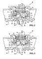
- Figure 2 is an enlarged partial schematic cross sectional view of the fuel vapor vent valve assembly, showing an anti-trickle valve in a first position.
- Figure 3 is an enlarged partial schematic cross sectional view of the fuel vapor vent valve assembly, showing the anti-trickle valve in a second position.
- Figure 4 is a schematic perspective cross sectional view of the anti-trickle valve when at rest and subjected to a vacuum pressure.
- Figure 5 is a schematic perspective cross sectional view of the anti-trickle valve during a change in motion and subjected to a positive vapor pressure.
- a fuel vapor vent valve assembly is shown generally at 20.
- the fuel vapor vent valve assembly 20 is for a fuel tank 22 of a vehicle (not shown).
- the fuel vapor vent valve assembly 20 controls the flow of vapors out of and into the fuel tank 22 to regulate a vapor pressure head within an interior 21 of the fuel tank 22. Accordingly, the fuel vapor vent valve assembly 20 releases fuel vapors and/or air from within the fuel tank 22 to vent the fuel tank 22 and permits air flow into the fuel tank 22 in response to a vacuum pressure within the fuel tank 22.
- the fuel vapor vent valve assembly 20 includes a housing 24.
- the housing 24 defines an outlet 26, a vapor port 28, and an interior opening 30 in fluid communication with the outlet 26 and the vapor port 28.
- the outlet 26 may be, but is not required to be, connected to some other component, such as a vapor canister (not shown). However, the outlet 26 is maintained at atmospheric pressure. Any vapors vented from the fuel tank 22 are exhausted through the outlet 26.
- the vapor port 28 is in fluid communication with fuel tank 22.
- the interior opening 30 of the housing 24 is disposed between the outlet 26 and the vapor port 28.
- the fuel vapor vent valve assembly 20 includes a liquid/vapor discriminator 32a, 32b, commonly referred to as a roll-over valve.
- the liquid/vapor discriminator 32a, 32b is coupled to the housing 24, adjacent to and in fluid communication with the vapor port 28. Accordingly, the vapor port 28 connects the interior opening 30 of the housing 24 and the liquid/vapor discriminator 32a, 32b.
- the liquid/vapor discriminator 32a, 32b is movable between an open position and a closed position. When in the open position, the liquid/vapor discriminator 32a, 32b allows fluid communication, particularly vapor communication, between an interior of the fuel tank 22 and the interior opening 30 of the housing 24.
- the liquid/vapor discriminator 32a, 32b When in the closed position, the liquid/vapor discriminator 32a, 32b is configured to prevent fluid communication, including vapor communication, between the interior of the fuel tank 22 and the interior opening 30 of the housing 24.
- the liquid/vapor discriminator 32a, 32b operates to prevent liquid fuel spillage from the fuel tank 22 when the fuel tank 22 is disposed at extreme angles or upside-down, such as during a roll-over event.
- the liquid/vapor discriminator 32a, 32b may be designed and/or configured in any suitable manner that restricts liquid fuel from spilling from the fuel tank 22 when the fuel tank is disposed at an extreme angle or upside down.
- the fuel vapor vent valve assembly 20 includes a first liquid/vapor discriminator 32a and a second liquid/vapor discriminator 32b.
- the first liquid/vapor discriminator 32a and the second liquid/vapor discriminator 32b are vertically offset from each other to open and/or close fluid communication between the fuel tank 22 and the interior opening 30 of the housing 24 at different fuel levels within the fuel tank 22.
- the fuel vapor vent assembly need not include both the first liquid/vapor discriminator 32a and the second liquid/vapor discriminator 32b.
- first liquid/vapor discriminator 32a and the second liquid/vapor discriminator 32b need not both be disposed in the housing 24, i.e, the first liquid/vapor discriminator 32a and the second liquid/vapor discriminator 32b may be separate and independent units.
- the fuel vapor vent valve assembly 20 further includes an anti-trickle valve 34.
- the anti-trickle valve 34 is disposed within the interior opening 30 of the housing 24.
- the anti-trickle valve 34 opens and closes fluid communication between the interior opening 30 of the housing 24 and the first liquid/vapor discriminator 32a when the first liquid/vapor discriminator 32a is in the open position.
- the anti-trickle valve 34 opens and closes fluid communication, particularly vapor communication, to selectively allow fluid communication, i.e., vapor communication, between the interior opening 30 of the housing 24 and the interior of the fuel tank 22.
- the anti-trickle valve 34 operates to prevent overfilling of the fuel tank 22, particularly when a low vapor pressure exists within the fuel tank 22. For example, during refueling of the fuel tank 22, when the second liquid/vapor discriminator 32b is completely closed due to a rise in the incoming fuel level, the anti-trickle valve 34 blocks the vapor port 28 to the first liquid/vapor discriminator 32a to prevent "trickle fill" of fuel into the fuel tank 22, and thereby prevent overfilling of the fuel tank 22.
- the anti-trickle valve 34 includes a casing 36 defining a first cavity 38 and a second cavity 40 that is separate from the first cavity 38.
- the casing 36 may include a bottom portion 42 and an upper portion 44, with the upper portion 44 securely affixed to the bottom portion 42.
- the upper portion 44 and the bottom portion 42 cooperate to define the first cavity 38 and the second cavity 40.
- the casing 36 defines an upper dynamic vapor passage 46a, 46b and a lower dynamic vapor passage 48.
- the upper dynamic vapor passage 46a, 46b is configured for communicating vapor between the interior opening 30 of the housing 24 and the first cavity 38.
- the lower dynamic vapor passage 48 is configured for communicating vapor between the first cavity 38 and the vapor port 28, and thereby to the liquid/vapor discriminator 32a.
- the upper dynamic vapor passage 46a, 46b may include, but is not limited to, a first upper dynamic vapor passage 46a and a second upper dynamic vapor passage 46b.
- the second upper dynamic vapor passage 46b is laterally offset and spaced from the first upper dynamic vapor passage 46a.
- the casing 36 further defines an upper vacuum relief vapor passage 50 and a lower vacuum relief vapor passage 52a, 52b.
- the upper vacuum relief vapor passage 50 is configured for communicating vapor between the interior opening 30 of the housing 24 and the second cavity 40.
- the lower vacuum relief vapor passage 52a, 52b communicates vapor between the second cavity 40 and the vapor port 28, and thereby to the liquid/vapor discriminator 32.
- the lower vacuum relief vapor passage 52a, 52b may include, but is not limited to, a first lower vacuum relief vapor passage 52a and a second lower vacuum relief vapor passage 52b.
- the second lower vacuum relief vapor passage 52b is laterally offset and spaced from the first lower vacuum relief vapor passage 52a.
- the bottom portion 42 of the casing 36 defines the lower dynamic vapor passage 48 and the lower vacuum relief vapor passage 52a, 52b, and the upper portion 44 defines the upper dynamic vapor passage 46a, 46b and the upper vacuum relief vapor passage 50.
- the casing 36 may be configured differently than as shown and described herein.
- the anti-trickle valve 34 includes a dynamic pressure relief mechanism 54.
- the dynamic pressure relief mechanism 54 includes a movable element 56.
- the movable element 56 is configured for opening fluid communication, particularly vapor communication, between the interior opening 30 of the housing 24 and the vapor port 28, and more specifically with the liquid/vapor discriminator 32, in response to a change in motion.
- the movable element 56 opens fluid communication in response to movement of the vehicle to vent vapor pressure from the interior of the fuel tank 22 during movement of the vehicle.
- the movable element 56 moves to open vapor communication between interior opening 30 of the housing 24 and the fuel tank 22 to vent the increased vapor pressure.
- the movable element 56 is disposed within the first cavity 38.
- the movable element 56 may include, but is not limited to, a spherical element.
- movable element 56 may include a stainless steel ball.
- the movable element 56 may be configured other than shown and described herein.
- the casing 36 of the anti-trickle valve 34 includes a concave ramp 58. More specifically, an upper surface 60 of the lower portion of the casing 36 defines the concave ramp 58.
- the concave ramp 58 is concentric with the lower dynamic vapor passage 48. As shown in Figure 4 , the concave ramp 58 centers the movable element 56 over the dynamic vapor passage when the vehicle is at rest. As such, when there is no change in valve motion, the movable element 56 moves down the concave ramp 58 into sealing engagement with the lower dynamic vapor passage 48 to prevent fluid communication, i.e., vapor communication between the fuel tank 22 and the outlet 26.
- the movable element 56 is movable upward along the concave ramp 58 in response to a change in motion of the vehicle, i.e., acceleration of the vehicle, to open fluid communication between the upper dynamic vapor passage 46a, 46b and the lower dynamic vapor passage 48.
- Acceleration of the vehicle i.e., a change in motion of the vehicle, may include, but is not limited to horizontal acceleration, vertical acceleration and/or radial acceleration.
- the movable element 56 moves up the concave ramp 58 out of sealing engagement with the lower dynamic vapor passage 48, to permit fluid communication, i.e., vapor communication, between the fuel tank 22 and the outlet 26.
- the movable element 56 includes a mass sufficient for the movable element 56 to resist movement up the concave ramp 58 by vapor pressure having a value above a predetermined level.
- the moveable element 56 may include a mass sufficient to resist movement up the concave ramp 58 by vapor pressure having a value of at least 3 kPa.
- the predetermined level may include a vapor pressure other than the 3 kPa described above, and may be set based upon any specific design considerations.
- a vapor pressure within the fuel tank 22, and more specifically at the vapor port 28, of below the predetermined level, e.g., below 3 kPa, will not move the movable element 56 up the concave ramp 58, while a vapor pressure greater than the predetermined level, e.g., greater than 3 kPa, may move the movable element 56 up the concave ramp 58, thereby opening fluid communication between the fuel tank 22 and the outlet 26.
- the anti-trickle valve 34 includes a vacuum relief mechanism 62.
- the vacuum relief mechanism 62 opens fluid communication between the interior opening 30 of the housing 24 and the vapor port 28, and more specifically the liquid/vapor discriminator 32a, to relieve vacuum pressure within the fuel tank 22.
- the vacuum relief mechanism 62 includes a float 64 disposed within the second cavity 40.
- the float 64 may include, but is not limited to, a plastic spherical ball or the like.
- the upper vacuum relief vapor passage 50 includes a circular port.
- the float 64 is configured to seal against the circular port of the upper vacuum relief vapor passage 50 in response to the vapor pressure from within the fuel tank 22 having a value greater than a selected vacuum level, such as 0 kPa, to bias the float 64 upwards.
- the vapor pressure at the vapor port 28, and more specifically when the vapor pressure at the fuel tank 22, is greater than 0 kPa in this example, the vapor pressure moves the float 64 into sealing engagement with the upper vacuum relief vapor passage 50 to block fluid communication, particularly vapor communication, between the interior opening 30 of the housing 24 and the fuel tank 22.
- the float 64 is configured to withdraw from sealing engagement with the circular port of the upper vacuum relief vapor passage 50 in response to a vacuum pressure from within the fuel tank 22, which draws the float 64 downwards to open fluid communication between the upper vacuum relief vapor passage 50 and the lower vacuum relief vapor passage 52a, 52b.
- a selected vacuum pressure level i.e., a pressure less than 0 kPa
- the vacuum pressure draws the float 64 vertically downward away from and out of sealing engagement with the upper vacuum relief vapor passage 50, thereby opening fluid communication, and particularly vapor communication, between the interior opening 30 of the housing 24 and the fuel tank 22 to permit air to enter the fuel tank 22 and fill the vacuum.
- the casing 36 may include a plurality of ribs 66 radially spaced about and adjacent the lower vacuum relief vapor passage 52a, 52b. More specifically, the upper surface 60 of the lower portion of the casing 36 defines the ribs 66.
- the ribs 66 vertically space the float 64 from the lower vacuum relief vapor passage 52a, 52b when the float 64 is drawn vertically downward by a vacuum pressure. As such, the ribs 66 prevent the vacuum pressure from drawing the float 64 downward into sealing engagement with the lower vacuum relief vapor passage 52.
- the housing 24 includes a ridge 68 disposed circumferentially about the vapor port 28, the lower dynamic vapor passage 48 and the lower vacuum relief vapor passage 52a, 52b.
- the ridge 68 may include any suitable shape, including but not limited to, a circular shape or a rectangular shape.
- the anti-trickle valve 34 is movable between a first position, shown in Figure 2 , and a second position, shown in Figure 3 .
- first position the anti-trickle valve 34 is disposed in sealing engagement with the ridge 68 to seal the vapor port 28, the lower dynamic vapor passage 48 and the lower vacuum relief vapor passage 52a, 52b from the interior opening 30 of the housing 24.
- second position the anti-trickle valve 34 is vertically spaced from the ridge 68 to permit fluid communication, and particularly vapor communication, around a periphery of the anti-trickle valve 34 between the vapor port 28 and the outlet 26.
- the housing 24 may define a plurality of flow channels (not shown) disposed about the periphery of the casing 36 to facilitate fluid communication around the periphery of the anti-trickle valve 34.
- the fuel vapor vent valve assembly 20 further includes a biasing device 70.
- the biasing device 70 is configured for biasing the anti-trickle valve 34 into the first position.
- the biasing device 70 may include, but is not limited to, a coil spring or the like.
- the biasing device 70 has a stiffness sufficient to resist movement of the anti-trickle valve 34 when it responds to a vapor pressure from within the fuel tank 22 having a value less than a first predetermined value (e.g., less than 3 kPa). Accordingly, if the vapor pressure within the fuel tank 22 and at the vapor port 28 is less than 3 kPa, then the biasing device 70 maintains the anti-trickle valve 34 in the first position.
- the pressure exerted on the anti-trickle valve 34 from the vapor pressure is sufficient to move the biasing device 70, e.g., compress the coil spring, and move the anti-trickle valve 34 into the second position.
- the biasing device 70 e.g., compress the coil spring
Landscapes
- Engineering & Computer Science (AREA)
- General Engineering & Computer Science (AREA)
- Mechanical Engineering (AREA)
- Cooling, Air Intake And Gas Exhaust, And Fuel Tank Arrangements In Propulsion Units (AREA)
- Supplying Secondary Fuel Or The Like To Fuel, Air Or Fuel-Air Mixtures (AREA)
- Self-Closing Valves And Venting Or Aerating Valves (AREA)
Claims (13)
- Kraftstoffdampf-Entlüftungsventilanordnung (20) für einen Kraftstofftank (22), wobei die Kraftstoffdampf-Entlüftungsventilanordnung (20) aufweist:ein Gehäuse (24), das einen Auslass (26) enthält und eine innere Öffnung definiert, die mit dem Auslass (26) in Fluidverbindung steht;einen Flüssigkeit/Dampf-Unterscheider (32a), der mit dem Gehäuse (24) gekoppelt und zwischen einer offenen Stellung und einer geschlossenen Stellung bewegbar ist, wobei der Flüssigkeit/Dampf-Unterscheider (32a) in der offenen Stellung eine Fluidverbindung zwischen einem Innenraum des Kraftstofftanks (22) und der inneren Öffnung (30) des Gehäuses (24) ermöglicht und der Flüssigkeit/Dampf-Unterscheider (32a) in der geschlossenen Stellung eine Fluidverbindung zwischen dem Innenraum des Kraftstofftanks (22) und der inneren Öffnung (30) des Gehäuses (24) verhindert; undein Überfüllsicherungsventil (34), das ein Gehäuse (36) enthält, das innerhalb der inneren Öffnung (30) des Gehäuses (24) angeordnet ist, wobei das Überfüllsicherungsventil (34) eine Fluidverbindung zwischen der inneren Öffnung (30) des Gehäuses (24) und dem Flüssigkeit/Dampf-Unterscheider (32a) öffnet und schließt, um wahlweise eine Fluidübertragung zwischen der inneren Öffnung (30) des Gehäuses (24) und dem Innenraum des Kraftstofftanks (22) zuzulassen, wenn sich der Flüssigkeit/Dampf-Cnterscheider (32a) in der offenen Stellung befindet;wobei das Überfüllsicherungsventil (34) eine dynamische Überdruckentlastungseinrichtung (54) enthält, die ein bewegbares Element (56) aufweist, das eine Fluidverbindung zwischen der inneren Öffnung (30) des Gehäuses (24) und dem Flüssigkeit/Dampf-Unterscheider (32a) in Abhängigkeit von einer Bewegungsänderung des bewegbaren Elementes (56) öffnet, um Dampfdruck aus dem Innenraum des Kraftstofftanks (22) abzulassen; undwobei das Überfüllsicherungsventil (34) eine Unterdruckentlastungseinrichtung (62) enthält, die konfiguriert ist, um eine Fluidverbindung zwischen der inneren Öffnung (30) des Gehäuses (24) und dem Flüssigkeit/Dampf-Unterscheider (32a) zu öffnen, um einen Unterdruck innerhalb des Kraftstofftanks (22) abzulassen, dadurch gekennzeichnet, dass das Gehäuse (36) einen ersten Hohlraum (38) und einen von dem ersten Hohlraum (38) gesonderten zweiten Hohlraum (40) bildet, wobei das bewegbare Element (56) der dynamischen Überdruckentlastungseinrichtung (54) innerhalb des ersten Hohlraums (38) angeordnet ist und die Unterdruckentlastungseinrichtung (62) innerhalb des zweiten Hohlraums (40) angeordnet ist.
- Kraftstoffdampf-Entlüftungsventilanordnung (20) nach Anspruch 1, wobei das Gehäuse (36) einen oberen dynamischen Dampfdurchgang (46a, 46b) und einen unteren dynamischen Dampfdurchgang (48) bildet, wobei der obere dynamische Dampfdurchgang (46a, 46b) zur Übertragung von Dampf zwischen der inneren Öffnung (30) des Gehäuses (24) und dem ersten Hohlraum (38) eingerichtet ist und der untere dynamische Dampfdurchgang (48) zur Übertragung von Dampf zwischen dem ersten Hohlraum (38) und dem Flüssigkeit/Dampf-Unterscheider (32a) eingerichtet ist.
- Kraftstoffdampf-Entlüftungsventilanordnung (20) nach Anspruch 2, wobei das Gehäuse (36) eine konkave Rampe (58) enthält, die zu dem unteren dynamischen Dampfdurchgang (48) konzentrisch und zur Zentrierung des bewegbaren Elementes (56) über dem dynamischen Dampfdurchgang, wenn es sich in Ruhestellung befindet, eingerichtet ist, wobei das bewegbare Element (56) in Abhängigkeit von einer Bewegungsänderung entlang der konkaven Rampe (58) nach oben bewegbar ist, um eine Fluidverbindung zwischen dem oberen dynamischen Dampfdurchgang (46a, 46b) und dem unteren dynamischen Dampfdurchgang (48) zu öffnen.
- Kraftstoffdampf-Entlüftungsventilanordnung (20) nach Anspruch 3, wobei das bewegbare Element (56) ein sphärisches Element enthält.
- Kraftstoffdampf-Entlüftungsventilanordnung (20) nach Anspruch 4, wobei das bewegbare Element (56) eine Masse aufweist, die ausreicht, um einer Bewegung nach oben entlang der konkaven Rampe (58) aufgrund eines Dampfdrucks, der einen Wert aufweist, der größer als ein vorbestimmtes Niveau ist, zu widerstehen.
- Kraftstoffdampf-Entlüftungsventilanordnung (20) nach Anspruch 1, wobei die Unterdruckentlastungseinrichtung (62) einen Schwimmer (64) enthält, der in dem zweiten Hohlraum (40) angeordnet ist.
- Kraftstoffdampf-Entlüftungsventilanordnung (20) nach Anspruch 6, wobei das Gehäuse (36) einen oberen Unterdruckentlastungsdampfdurchgang (50) und einen unteren Unterdruckentlastungsdampfdurchgang (52a, 52b) bildet, wobei der obere Unterdruckentlastungsdampfdurchgang (50) zur Übertragung von Dampf zwischen der inneren Öffnung (30) des Gehäuses (24) und dem zweiten Hohlraum (40) eingerichtet ist und der untere Unterdruckentlastungsdampfdurchgang (52a, 52b) zur Übertragung von Dampf zwischen dem zweiten Hohlraum (40) und dem Flüssigkeit/Dampf-Unterscheider (32a) eingerichtet ist.
- Kraftstoffdampf-Entlüftungsventilanordnung (20) nach Anspruch 7, wobei der obere Unterdruckentlastungsdampfdurchgang (50) eine runde Kanalöffnung enthält und der Schwimmer (64) ein sphärisches Element enthält, wobei der Schwimmer (64) eingerichtet ist, um in Abhängigkeit davon, dass ein Dampfdruck aus dem Inneren des Kraftstofftanks (22) ein ausgewähltes Unterdruckniveau überschreitet, gegen die runde Kanalöffnung des oberen Unterdruckentlastungsdampfdurchgangs (50) abzudichten, und der Schwimmer (64) eingerichtet ist, um in Abhängigkeit davon, dass ein Unterdruck aus dem Inneren des Kraftstofftanks (22) geringer ist als das ausgewählte Unterdruckniveau, sich von der abdichtenden Eingriffsverbindung mit der runden Anschlussöffnung des Unterdruckentlastungsdampfdurchgangs (50) zurückzuziehen, um eine Fluidverbindung zwischen dem oberen Unterdruckentlastungsdampfdurchgang (50) und dem unteren Unterdruckentlastungsdampfdurchgang (52a, 52b) zu öffnen.
- Kraftstoffdampf-Entlüftungsventilanordnung (20) nach Anspruch 8, wobei das Gehäuse (36) mehrere Rippen (66) enthält, die radial im Abstand rings um den und benachbart zu dem unteren Unterdruckentlastungsdampfdurchgang (52a, 52b) angeordnet sind.
- Kraftstoffdampf-Entlüftungsventilanordnung (20) nach Anspruch 1, wobei das Gehäuse (24) einen Entlüftungskanal (28) bildet, der die innere Öffnung (30) und den Flüssigkeit/Dampf-Unterscheider (32a) miteinander verbindet.
- Kraftstoffdampf-Entlüftungsventilanordnung (20) nach Anspruch 10, wobei das Gehäuse (24) eine Erhöhung (68) enthält, die umlaufend rings um den Dampfkanal (28), den unteren dynamischen Dampfdurchgang (48) und den unteren Unterdruckentlastungsdampfdurchgang (52a, 52b) angeordnet ist, wobei das Überfüllsicherungsventil (34) zwischen einer ersten Stellung, in der das Überfüllsicherungsventil (34) in dichtender Eingriffsverbindung mit der Erhöhung (38) steht, um den Dampfkanal (28), den unteren dynamischen Dampfdurchgang (48) und den unteren Unterdruckentlastungsdampfdurchgang (52a, 52b) gegenüber der inneren Öffnung (30) des Gehäuses (24) dichtend zu verschließen, und einer zweiten Stellung bewegbar ist, in der das Überfüllsicherungsventil (34) von der Erhöhung (68) beabstandet ist, um eine Fluidübertragung über einen Umfang des Uberfüllsicherungsventils (34) zwischen dem Dampfkanal (28) und dem Auslass (26) zuzulassen.
- Kraftstoffdampf-Entlüftungsventilanordnung (20) nach Anspruch 11, die ferner eine Vorspanneinrichtung (70) enthält, die eingerichtet ist, um das Überfüllsicherungsventil (34) in die erste Stellung vorzuspannen, und eine Steifigkeit aufweist, die ausreicht, um einer Bewegung des Überfüllsicherungsventils (34) in Abhängigkeit davon, dass ein Dampfdruck aus dem Inneren des Kraftstofftanks (22) einen kleineren Wert als ein vorbestimmtes Niveau aufweist, zu widerstehen.
- Kraftstoffdampf-Entluftungsventilanordnung (20) nach Anspruch 1, wobei das Gehäuse (36) einen unteren Abschnitt (42) und einen oberen Abschnitt (44) enthält, der fest an dem unteren Abschnitt (42) befestigt ist, wobei der obere Abschnitt (44) einen oberen dynamischen Dampfdurchgang (46a, 46b) und einen oberen Unterdruckentlastungsdampfdurchgang (50) bildet und der untere Abschnitt (42) einen unteren dynamischen Dampfdurchgang (48) und einen unteren Unterdruckentlastungsdampfdurchgang (52a, 52b) bildet.
Priority Applications (1)
| Application Number | Priority Date | Filing Date | Title |
|---|---|---|---|
| PL10725850T PL2430342T3 (pl) | 2009-05-11 | 2010-05-11 | Zawór odpowietrzający pary paliwa z dynamicznym uwalnianiem ciśnienia |
Applications Claiming Priority (2)
| Application Number | Priority Date | Filing Date | Title |
|---|---|---|---|
| US17699809P | 2009-05-11 | 2009-05-11 | |
| PCT/IB2010/001082 WO2010131099A1 (en) | 2009-05-11 | 2010-05-11 | Fuel vapor vent valve with dynamic pressure relief |
Publications (2)
| Publication Number | Publication Date |
|---|---|
| EP2430342A1 EP2430342A1 (de) | 2012-03-21 |
| EP2430342B1 true EP2430342B1 (de) | 2013-02-13 |
Family
ID=42668249
Family Applications (1)
| Application Number | Title | Priority Date | Filing Date |
|---|---|---|---|
| EP20100725850 Not-in-force EP2430342B1 (de) | 2009-05-11 | 2010-05-11 | Entlüftungsventil für kraftstoffdämpfe mit dynamischer druckentlastung |
Country Status (9)
| Country | Link |
|---|---|
| US (1) | US8371326B2 (de) |
| EP (1) | EP2430342B1 (de) |
| JP (1) | JP5678346B2 (de) |
| KR (1) | KR101630900B1 (de) |
| CN (2) | CN201866351U (de) |
| AU (1) | AU2010247088B2 (de) |
| MX (1) | MX2011012097A (de) |
| PL (1) | PL2430342T3 (de) |
| WO (1) | WO2010131099A1 (de) |
Families Citing this family (23)
| Publication number | Priority date | Publication date | Assignee | Title |
|---|---|---|---|---|
| US8371326B2 (en) * | 2009-05-11 | 2013-02-12 | Eaton Corporation | Fuel vapor vent valve with dynamic pressure relief |
| US8342453B2 (en) * | 2010-02-09 | 2013-01-01 | Thunder Bay Aircraft Leasing Inc. | System for airborne transport of flammable liquids |
| CN103348168B (zh) * | 2011-02-28 | 2015-04-22 | 博格华纳公司 | 用于液压张紧器的可变流量止回阀 |
| DE102011116941A1 (de) | 2011-10-26 | 2013-05-02 | Kautex Textron Gmbh & Co. Kg | Entlüftungsventil |
| US9360872B2 (en) | 2011-12-22 | 2016-06-07 | Eaton Corporation | Fuel tank vent valve assembly and method of assembly |
| CN104053565B (zh) * | 2012-03-22 | 2017-10-03 | 株式会社利富高 | 燃料箱用阀装置 |
| CN103362705B (zh) * | 2012-03-29 | 2016-12-14 | 比亚迪股份有限公司 | 一种燃油箱保护阀及具有该保护阀的燃油箱 |
| FR2991298B1 (fr) | 2012-05-29 | 2015-04-03 | Eurocopter France | Reservoir, systeme de stockage de carburant, et aeronef |
| FR2996279B1 (fr) * | 2012-09-28 | 2015-07-03 | Inergy Automotive Systems Res | Clapet de ventilation pour reservoir a liquide integrant une securite anti-surpression. |
| FR3003543B1 (fr) | 2013-03-22 | 2015-12-25 | Eurocopter France | Reservoir muni d'un clapet de surpression |
| KR20150095534A (ko) * | 2014-02-13 | 2015-08-21 | 이턴 코포레이션 | 연료 탱크 통기 밸브 조립체 및 조립 방법 |
| WO2015127477A1 (en) * | 2014-02-24 | 2015-08-27 | Eaton Corporation | Fuel tank liquid vapor discriminator with integrated over-pressure and make-up air valves |
| JP6334960B2 (ja) * | 2014-03-05 | 2018-05-30 | 株式会社パイオラックス | 燃料タンク用弁装置 |
| WO2015133039A1 (ja) * | 2014-03-05 | 2015-09-11 | 株式会社パイオラックス | 燃料タンク用弁装置 |
| US10035091B2 (en) * | 2014-03-17 | 2018-07-31 | Kyosan Denki Co., Ltd. | Liquid fuel catcher |
| CN108138978A (zh) * | 2015-07-29 | 2018-06-08 | A.R.I.流体控制附件有限公司 | 流体流动阀 |
| US9939073B2 (en) * | 2016-02-04 | 2018-04-10 | FlowTech Fueling, LLC | Breather check valve |
| BR102018067630B1 (pt) * | 2018-09-03 | 2020-10-27 | Miguel Greyde Avila Dias | válvula termodinâmica retentora de vapores e gases e de alívio de pressão e vácuo |
| US11846360B2 (en) | 2018-11-14 | 2023-12-19 | Franklin Fueling Systems, Llc | Pressure vacuum valve |
| WO2021132035A1 (ja) * | 2019-12-24 | 2021-07-01 | 株式会社パイオラックス | 弁装置 |
| US12504087B2 (en) * | 2020-11-10 | 2025-12-23 | Eaton Intelligent Power Limited | Valve assembly and a method of forming the valve assembly |
| US11795049B2 (en) | 2020-12-30 | 2023-10-24 | Vapor Systems Technologies, Inc. | Pressure/vacuum (PV) valve for fuel storage tanks, in-line pressure-vacuum valve test unit, and combination thereof |
| CN115750859B (zh) * | 2022-10-20 | 2026-01-13 | 新乡航空工业(集团)有限公司 | 适配于气液分离器的排气泄压装置 |
Family Cites Families (22)
| Publication number | Priority date | Publication date | Assignee | Title |
|---|---|---|---|---|
| US3970098A (en) * | 1974-11-01 | 1976-07-20 | Southwest Wheel And Manufacturing Company | Tank vent |
| US4023583A (en) * | 1975-11-10 | 1977-05-17 | Brown-Minneapolis Tank & Fabricating Co. | Vent valve with back pressure check |
| DE3442149C2 (de) | 1984-11-17 | 1987-04-23 | Adam Opel AG, 6090 Rüsselsheim | Vorrichtung zur Füllbegrenzung sowie zur Be- und Entlüftung von Kraftstoffbehältern von Kraftfahrzeugen |
| US5014742A (en) | 1990-04-05 | 1991-05-14 | General Motors Corporation | Vacuum actuated tank vapor vent valve |
| JP2853572B2 (ja) * | 1994-04-28 | 1999-02-03 | 豊田合成株式会社 | 双方向弁および燃料遮断装置 |
| US5666989A (en) * | 1994-11-08 | 1997-09-16 | Stant Manufacturing Inc. | Tank venting control assembly |
| US5992441A (en) | 1995-11-08 | 1999-11-30 | Borg-Warner Automotive, Inc. | Fuel vapor vent valve |
| KR100312559B1 (ko) | 1998-12-30 | 2002-02-28 | 이계안 | 자동차용롤오버밸브 |
| IL128937A (en) | 1999-03-11 | 2002-09-12 | Raval Agriculture Coop Soc Ltd | Multi-purpose valve |
| US6612324B2 (en) | 2001-03-19 | 2003-09-02 | Saturn Electronics & Engineering, Inc. | Fill limit vapor valve with variable vapor venting capability |
| US7063101B2 (en) | 2003-08-01 | 2006-06-20 | Stant Manufacturing Inc. | Fuel tank vent system |
| US6918405B2 (en) | 2003-12-04 | 2005-07-19 | Alfmeier Corporation | Fill limit vent valve |
| US7147017B2 (en) | 2004-06-28 | 2006-12-12 | Alfmeier Corporation | Fill limit vent valve assembly |
| US7163023B2 (en) | 2004-07-15 | 2007-01-16 | Eaton Corporation | Fuel vapor vent valve float assembly and method of making same |
| JP2006044586A (ja) * | 2004-08-06 | 2006-02-16 | Piolax Inc | 燃料タンク用チェックバルブ |
| US7143783B2 (en) * | 2004-08-13 | 2006-12-05 | Siegfried Emke | Fuel tank cap safety valve with splash control and overpressure release |
| US7207347B2 (en) | 2004-08-23 | 2007-04-24 | Raval A.S.C. Ltd. | Dual function valve for fuel tank |
| FR2877650B1 (fr) | 2004-11-05 | 2008-07-04 | Marwal Systems Snc | Dispositif de ventilation de reservoir |
| IL165845A0 (en) * | 2004-12-16 | 2006-01-15 | Raval Acs Ltd | Vapor recovery control valve |
| US7201155B2 (en) | 2005-03-15 | 2007-04-10 | Eaton Corporation | Integral vapor storage and vent valve assembly for use with a small engine fuel tank and vapor emission system employing same |
| JP4742994B2 (ja) | 2005-09-28 | 2011-08-10 | 豊田合成株式会社 | 燃料遮断弁 |
| US8371326B2 (en) * | 2009-05-11 | 2013-02-12 | Eaton Corporation | Fuel vapor vent valve with dynamic pressure relief |
-
2010
- 2010-04-27 US US12/767,856 patent/US8371326B2/en not_active Expired - Fee Related
- 2010-05-11 JP JP2012510380A patent/JP5678346B2/ja not_active Expired - Fee Related
- 2010-05-11 CN CN2010202734806U patent/CN201866351U/zh not_active Expired - Fee Related
- 2010-05-11 KR KR1020117029604A patent/KR101630900B1/ko not_active Expired - Fee Related
- 2010-05-11 MX MX2011012097A patent/MX2011012097A/es not_active Application Discontinuation
- 2010-05-11 AU AU2010247088A patent/AU2010247088B2/en not_active Ceased
- 2010-05-11 PL PL10725850T patent/PL2430342T3/pl unknown
- 2010-05-11 EP EP20100725850 patent/EP2430342B1/de not_active Not-in-force
- 2010-05-11 CN CN201010241541.5A patent/CN101968134B/zh not_active Expired - Fee Related
- 2010-05-11 WO PCT/IB2010/001082 patent/WO2010131099A1/en not_active Ceased
Also Published As
| Publication number | Publication date |
|---|---|
| AU2010247088A1 (en) | 2011-12-01 |
| KR101630900B1 (ko) | 2016-06-15 |
| JP2012526701A (ja) | 2012-11-01 |
| KR20120023775A (ko) | 2012-03-13 |
| CN101968134A (zh) | 2011-02-09 |
| MX2011012097A (es) | 2012-01-25 |
| US8371326B2 (en) | 2013-02-12 |
| CN201866351U (zh) | 2011-06-15 |
| EP2430342A1 (de) | 2012-03-21 |
| JP5678346B2 (ja) | 2015-03-04 |
| CN101968134B (zh) | 2014-04-23 |
| PL2430342T3 (pl) | 2013-07-31 |
| AU2010247088B2 (en) | 2013-07-25 |
| WO2010131099A1 (en) | 2010-11-18 |
| US20100282335A1 (en) | 2010-11-11 |
Similar Documents
| Publication | Publication Date | Title |
|---|---|---|
| AU2010247088B2 (en) | Fuel vapor vent valve with dynamic pressure relief | |
| US4760858A (en) | Fuel vapor control valve | |
| US5666989A (en) | Tank venting control assembly | |
| US6848463B2 (en) | Vapor vent valve | |
| EP1212560B1 (de) | Ventil und verfahren zur befestigung in einem behälter | |
| US7234452B2 (en) | Controlling vapor emission in a small engine fuel tank system | |
| EP1161634B1 (de) | Überlaufvermeidungs-, entlüftungs- und überrollventil | |
| US5960817A (en) | Control valve and system for fuel vapor recovery | |
| US6532983B2 (en) | System for venting a liquid tank | |
| US6591855B2 (en) | Fuel cutoff valve | |
| EP1782992B1 (de) | Überrollventil mit Unterdrucksicherheitsfunktion | |
| EP1705051B1 (de) | Tankentlüftungsventil | |
| EP2607135B1 (de) | Ventil für Kraftstoff-Belüftungssystem | |
| US20090236350A1 (en) | Ventilating device for fuel tank | |
| US20100224262A1 (en) | Valve for the venting circuit of a liquid tank | |
| US8297298B2 (en) | Vent control valve for a fuel tank | |
| US20070000542A1 (en) | Fuel tank valve | |
| US20030136444A1 (en) | Fuel valve | |
| US8763626B2 (en) | Valve for the venting circuit of a liquid tank | |
| EP2823980B1 (de) | Ventil zum Entlüften eines Kraftstofftanks | |
| US6530364B1 (en) | Ventilating device for motor vehicle fuel tank | |
| EP1171324B1 (de) | Füllbegrenzungsventilanordnung mit flüssigkraftstofffalle | |
| JP4487915B2 (ja) | 燃料遮断弁 |
Legal Events
| Date | Code | Title | Description |
|---|---|---|---|
| PUAI | Public reference made under article 153(3) epc to a published international application that has entered the european phase |
Free format text: ORIGINAL CODE: 0009012 |
|
| 17P | Request for examination filed |
Effective date: 20111210 |
|
| AK | Designated contracting states |
Kind code of ref document: A1 Designated state(s): AL AT BE BG CH CY CZ DE DK EE ES FI FR GB GR HR HU IE IS IT LI LT LU LV MC MK MT NL NO PL PT RO SE SI SK SM TR |
|
| DAX | Request for extension of the european patent (deleted) | ||
| GRAP | Despatch of communication of intention to grant a patent |
Free format text: ORIGINAL CODE: EPIDOSNIGR1 |
|
| GRAS | Grant fee paid |
Free format text: ORIGINAL CODE: EPIDOSNIGR3 |
|
| GRAA | (expected) grant |
Free format text: ORIGINAL CODE: 0009210 |
|
| AK | Designated contracting states |
Kind code of ref document: B1 Designated state(s): AL AT BE BG CH CY CZ DE DK EE ES FI FR GB GR HR HU IE IS IT LI LT LU LV MC MK MT NL NO PL PT RO SE SI SK SM TR |
|
| REG | Reference to a national code |
Ref country code: GB Ref legal event code: FG4D |
|
| REG | Reference to a national code |
Ref country code: AT Ref legal event code: REF Ref document number: 596684 Country of ref document: AT Kind code of ref document: T Effective date: 20130215 |
|
| REG | Reference to a national code |
Ref country code: SE Ref legal event code: TRGR |
|
| REG | Reference to a national code |
Ref country code: IE Ref legal event code: FG4D |
|
| REG | Reference to a national code |
Ref country code: DE Ref legal event code: R096 Ref document number: 602010005031 Country of ref document: DE Effective date: 20130418 |
|
| REG | Reference to a national code |
Ref country code: AT Ref legal event code: MK05 Ref document number: 596684 Country of ref document: AT Kind code of ref document: T Effective date: 20130213 |
|
| REG | Reference to a national code |
Ref country code: NL Ref legal event code: VDEP Effective date: 20130213 |
|
| REG | Reference to a national code |
Ref country code: LT Ref legal event code: MG4D |
|
| PG25 | Lapsed in a contracting state [announced via postgrant information from national office to epo] |
Ref country code: LT Free format text: LAPSE BECAUSE OF FAILURE TO SUBMIT A TRANSLATION OF THE DESCRIPTION OR TO PAY THE FEE WITHIN THE PRESCRIBED TIME-LIMIT Effective date: 20130213 Ref country code: IS Free format text: LAPSE BECAUSE OF FAILURE TO SUBMIT A TRANSLATION OF THE DESCRIPTION OR TO PAY THE FEE WITHIN THE PRESCRIBED TIME-LIMIT Effective date: 20130613 Ref country code: AT Free format text: LAPSE BECAUSE OF FAILURE TO SUBMIT A TRANSLATION OF THE DESCRIPTION OR TO PAY THE FEE WITHIN THE PRESCRIBED TIME-LIMIT Effective date: 20130213 Ref country code: NO Free format text: LAPSE BECAUSE OF FAILURE TO SUBMIT A TRANSLATION OF THE DESCRIPTION OR TO PAY THE FEE WITHIN THE PRESCRIBED TIME-LIMIT Effective date: 20130513 Ref country code: BG Free format text: LAPSE BECAUSE OF FAILURE TO SUBMIT A TRANSLATION OF THE DESCRIPTION OR TO PAY THE FEE WITHIN THE PRESCRIBED TIME-LIMIT Effective date: 20130513 Ref country code: ES Free format text: LAPSE BECAUSE OF FAILURE TO SUBMIT A TRANSLATION OF THE DESCRIPTION OR TO PAY THE FEE WITHIN THE PRESCRIBED TIME-LIMIT Effective date: 20130524 |
|
| REG | Reference to a national code |
Ref country code: PL Ref legal event code: T3 |
|
| PG25 | Lapsed in a contracting state [announced via postgrant information from national office to epo] |
Ref country code: SI Free format text: LAPSE BECAUSE OF FAILURE TO SUBMIT A TRANSLATION OF THE DESCRIPTION OR TO PAY THE FEE WITHIN THE PRESCRIBED TIME-LIMIT Effective date: 20130213 Ref country code: GR Free format text: LAPSE BECAUSE OF FAILURE TO SUBMIT A TRANSLATION OF THE DESCRIPTION OR TO PAY THE FEE WITHIN THE PRESCRIBED TIME-LIMIT Effective date: 20130514 Ref country code: FI Free format text: LAPSE BECAUSE OF FAILURE TO SUBMIT A TRANSLATION OF THE DESCRIPTION OR TO PAY THE FEE WITHIN THE PRESCRIBED TIME-LIMIT Effective date: 20130213 Ref country code: BE Free format text: LAPSE BECAUSE OF FAILURE TO SUBMIT A TRANSLATION OF THE DESCRIPTION OR TO PAY THE FEE WITHIN THE PRESCRIBED TIME-LIMIT Effective date: 20130213 Ref country code: LV Free format text: LAPSE BECAUSE OF FAILURE TO SUBMIT A TRANSLATION OF THE DESCRIPTION OR TO PAY THE FEE WITHIN THE PRESCRIBED TIME-LIMIT Effective date: 20130213 Ref country code: PT Free format text: LAPSE BECAUSE OF FAILURE TO SUBMIT A TRANSLATION OF THE DESCRIPTION OR TO PAY THE FEE WITHIN THE PRESCRIBED TIME-LIMIT Effective date: 20130613 |
|
| PG25 | Lapsed in a contracting state [announced via postgrant information from national office to epo] |
Ref country code: HR Free format text: LAPSE BECAUSE OF FAILURE TO SUBMIT A TRANSLATION OF THE DESCRIPTION OR TO PAY THE FEE WITHIN THE PRESCRIBED TIME-LIMIT Effective date: 20130213 |
|
| PG25 | Lapsed in a contracting state [announced via postgrant information from national office to epo] |
Ref country code: CZ Free format text: LAPSE BECAUSE OF FAILURE TO SUBMIT A TRANSLATION OF THE DESCRIPTION OR TO PAY THE FEE WITHIN THE PRESCRIBED TIME-LIMIT Effective date: 20130213 Ref country code: SK Free format text: LAPSE BECAUSE OF FAILURE TO SUBMIT A TRANSLATION OF THE DESCRIPTION OR TO PAY THE FEE WITHIN THE PRESCRIBED TIME-LIMIT Effective date: 20130213 Ref country code: EE Free format text: LAPSE BECAUSE OF FAILURE TO SUBMIT A TRANSLATION OF THE DESCRIPTION OR TO PAY THE FEE WITHIN THE PRESCRIBED TIME-LIMIT Effective date: 20130213 Ref country code: RO Free format text: LAPSE BECAUSE OF FAILURE TO SUBMIT A TRANSLATION OF THE DESCRIPTION OR TO PAY THE FEE WITHIN THE PRESCRIBED TIME-LIMIT Effective date: 20130213 Ref country code: DK Free format text: LAPSE BECAUSE OF FAILURE TO SUBMIT A TRANSLATION OF THE DESCRIPTION OR TO PAY THE FEE WITHIN THE PRESCRIBED TIME-LIMIT Effective date: 20130213 Ref country code: NL Free format text: LAPSE BECAUSE OF FAILURE TO SUBMIT A TRANSLATION OF THE DESCRIPTION OR TO PAY THE FEE WITHIN THE PRESCRIBED TIME-LIMIT Effective date: 20130213 |
|
| PLBE | No opposition filed within time limit |
Free format text: ORIGINAL CODE: 0009261 |
|
| STAA | Information on the status of an ep patent application or granted ep patent |
Free format text: STATUS: NO OPPOSITION FILED WITHIN TIME LIMIT |
|
| PG25 | Lapsed in a contracting state [announced via postgrant information from national office to epo] |
Ref country code: MC Free format text: LAPSE BECAUSE OF FAILURE TO SUBMIT A TRANSLATION OF THE DESCRIPTION OR TO PAY THE FEE WITHIN THE PRESCRIBED TIME-LIMIT Effective date: 20130213 Ref country code: IT Free format text: LAPSE BECAUSE OF FAILURE TO SUBMIT A TRANSLATION OF THE DESCRIPTION OR TO PAY THE FEE WITHIN THE PRESCRIBED TIME-LIMIT Effective date: 20130213 |
|
| 26N | No opposition filed |
Effective date: 20131114 |
|
| REG | Reference to a national code |
Ref country code: DE Ref legal event code: R097 Ref document number: 602010005031 Country of ref document: DE Effective date: 20131114 |
|
| REG | Reference to a national code |
Ref country code: IE Ref legal event code: MM4A |
|
| REG | Reference to a national code |
Ref country code: FR Ref legal event code: ST Effective date: 20140131 |
|
| PG25 | Lapsed in a contracting state [announced via postgrant information from national office to epo] |
Ref country code: IE Free format text: LAPSE BECAUSE OF NON-PAYMENT OF DUE FEES Effective date: 20130511 |
|
| PG25 | Lapsed in a contracting state [announced via postgrant information from national office to epo] |
Ref country code: FR Free format text: LAPSE BECAUSE OF NON-PAYMENT OF DUE FEES Effective date: 20130531 |
|
| PG25 | Lapsed in a contracting state [announced via postgrant information from national office to epo] |
Ref country code: PL Free format text: LAPSE BECAUSE OF NON-PAYMENT OF DUE FEES Effective date: 20130511 |
|
| REG | Reference to a national code |
Ref country code: PL Ref legal event code: LAPE |
|
| REG | Reference to a national code |
Ref country code: CH Ref legal event code: PL |
|
| GBPC | Gb: european patent ceased through non-payment of renewal fee |
Effective date: 20140511 |
|
| PG25 | Lapsed in a contracting state [announced via postgrant information from national office to epo] |
Ref country code: CH Free format text: LAPSE BECAUSE OF NON-PAYMENT OF DUE FEES Effective date: 20140531 Ref country code: LI Free format text: LAPSE BECAUSE OF NON-PAYMENT OF DUE FEES Effective date: 20140531 |
|
| PG25 | Lapsed in a contracting state [announced via postgrant information from national office to epo] |
Ref country code: MT Free format text: LAPSE BECAUSE OF FAILURE TO SUBMIT A TRANSLATION OF THE DESCRIPTION OR TO PAY THE FEE WITHIN THE PRESCRIBED TIME-LIMIT Effective date: 20130213 |
|
| PG25 | Lapsed in a contracting state [announced via postgrant information from national office to epo] |
Ref country code: GB Free format text: LAPSE BECAUSE OF NON-PAYMENT OF DUE FEES Effective date: 20140511 Ref country code: SM Free format text: LAPSE BECAUSE OF FAILURE TO SUBMIT A TRANSLATION OF THE DESCRIPTION OR TO PAY THE FEE WITHIN THE PRESCRIBED TIME-LIMIT Effective date: 20130213 |
|
| PG25 | Lapsed in a contracting state [announced via postgrant information from national office to epo] |
Ref country code: CY Free format text: LAPSE BECAUSE OF FAILURE TO SUBMIT A TRANSLATION OF THE DESCRIPTION OR TO PAY THE FEE WITHIN THE PRESCRIBED TIME-LIMIT Effective date: 20130213 Ref country code: TR Free format text: LAPSE BECAUSE OF FAILURE TO SUBMIT A TRANSLATION OF THE DESCRIPTION OR TO PAY THE FEE WITHIN THE PRESCRIBED TIME-LIMIT Effective date: 20130213 |
|
| PG25 | Lapsed in a contracting state [announced via postgrant information from national office to epo] |
Ref country code: MK Free format text: LAPSE BECAUSE OF FAILURE TO SUBMIT A TRANSLATION OF THE DESCRIPTION OR TO PAY THE FEE WITHIN THE PRESCRIBED TIME-LIMIT Effective date: 20130213 Ref country code: HU Free format text: LAPSE BECAUSE OF FAILURE TO SUBMIT A TRANSLATION OF THE DESCRIPTION OR TO PAY THE FEE WITHIN THE PRESCRIBED TIME-LIMIT; INVALID AB INITIO Effective date: 20100511 Ref country code: LU Free format text: LAPSE BECAUSE OF NON-PAYMENT OF DUE FEES Effective date: 20130511 |
|
| PGFP | Annual fee paid to national office [announced via postgrant information from national office to epo] |
Ref country code: DE Payment date: 20180419 Year of fee payment: 9 |
|
| PGFP | Annual fee paid to national office [announced via postgrant information from national office to epo] |
Ref country code: SE Payment date: 20180426 Year of fee payment: 9 |
|
| PG25 | Lapsed in a contracting state [announced via postgrant information from national office to epo] |
Ref country code: AL Free format text: LAPSE BECAUSE OF FAILURE TO SUBMIT A TRANSLATION OF THE DESCRIPTION OR TO PAY THE FEE WITHIN THE PRESCRIBED TIME-LIMIT Effective date: 20130213 |
|
| REG | Reference to a national code |
Ref country code: DE Ref legal event code: R082 Ref document number: 602010005031 Country of ref document: DE Ref country code: DE Ref legal event code: R081 Ref document number: 602010005031 Country of ref document: DE Owner name: EATON INTELLIGENT POWER LIMITED, IE Free format text: FORMER OWNER: EATON CORPORATION, CLEVELAND, OHIO, US |
|
| REG | Reference to a national code |
Ref country code: DE Ref legal event code: R119 Ref document number: 602010005031 Country of ref document: DE |
|
| PG25 | Lapsed in a contracting state [announced via postgrant information from national office to epo] |
Ref country code: SE Free format text: LAPSE BECAUSE OF NON-PAYMENT OF DUE FEES Effective date: 20190512 |
|
| PG25 | Lapsed in a contracting state [announced via postgrant information from national office to epo] |
Ref country code: DE Free format text: LAPSE BECAUSE OF NON-PAYMENT OF DUE FEES Effective date: 20191203 |
|
| REG | Reference to a national code |
Ref country code: SE Ref legal event code: EUG |