EP2430278B1 - Trépan hybride - Google Patents
Trépan hybride Download PDFInfo
- Publication number
- EP2430278B1 EP2430278B1 EP10775268.5A EP10775268A EP2430278B1 EP 2430278 B1 EP2430278 B1 EP 2430278B1 EP 10775268 A EP10775268 A EP 10775268A EP 2430278 B1 EP2430278 B1 EP 2430278B1
- Authority
- EP
- European Patent Office
- Prior art keywords
- bit
- earth
- fixed
- fixed blade
- rolling
- Prior art date
- Legal status (The legal status is an assumption and is not a legal conclusion. Google has not performed a legal analysis and makes no representation as to the accuracy of the status listed.)
- Active
Links
Images

Classifications
-
- E—FIXED CONSTRUCTIONS
- E21—EARTH DRILLING; MINING
- E21B—EARTH DRILLING, e.g. DEEP DRILLING; OBTAINING OIL, GAS, WATER, SOLUBLE OR MELTABLE MATERIALS OR A SLURRY OF MINERALS FROM WELLS
- E21B10/00—Drill bits
- E21B10/08—Roller bits
- E21B10/14—Roller bits combined with non-rolling cutters other than of leading-portion type
-
- E—FIXED CONSTRUCTIONS
- E21—EARTH DRILLING; MINING
- E21B—EARTH DRILLING, e.g. DEEP DRILLING; OBTAINING OIL, GAS, WATER, SOLUBLE OR MELTABLE MATERIALS OR A SLURRY OF MINERALS FROM WELLS
- E21B10/00—Drill bits
Definitions
- the present invention relates in general to earth-boring drill bits and, in particular, to a bit having a combination of rolling and fixed cutters and cutting elements as set forth in the independent claims.
- rock bits having one, two, or three rolling cutters rotatably mounted thereon are employed.
- the bit is secured to the lower end of a drillstring that is rotated from the surface or by a downhole motor or turbine.
- the cutters mounted on the bit roll and slide upon the bottom of the borehole as the drillstring is rotated, thereby engaging and disintegrating the formation material to be removed.
- the rolling cutters are provided with cutting elements or teeth that are forced to penetrate and gouge the bottom of the borehole by weight from the drillstring.
- the cuttings from the bottom and sides of the borehole are washed away by drilling fluid that is pumped down from the surface through the hollow, rotating drillstring, and are carried in suspension in the drilling fluid to the surface.
- Rolling cutter bits dominated petroleum drilling for the greater part of the 20 th century. With improvements in synthetic diamond technology that occurred in the 1970s and 1980s, the fixed-cutter, or “drag” bit, became popular again in the latter part of the 20 th century. Modern fixed-cutter bits are often referred to as “diamond” or “PDC” (polycrystalline diamond compact) bits and are far removed from the original fixed-cutter bits of the 19 th and early 20 th centuries.
- Diamond or PDC bits carry cutting elements comprising polycrystalline diamond compact layers or “tables” formed on and bonded to a supporting substrate, conventionally of cemented tungsten carbide, the cutting elements being arranged in selected locations on blades or other structures on the bit body with the diamond tables facing generally in the direction of bit rotation.
- Diamond bits have an advantage over rolling-cutter bits in that they generally have no moving parts.
- the drilling mechanics and dynamics of diamond bits are different from those of rolling-cutter bits precisely because they have no moving parts.
- diamond bits are used in a manner similar to that for rolling cutter bits, the diamond bits also being rotated against a formation being drilled under applied weight on bit to remove formation material. Engagement between the diamond cutting elements and the borehole bottom and sides shears or scrapes material from the formation, instead of using a crushing action as is employed by rolling-cutter bits.
- Rolling-cutter and diamond bits each have particular applications for which they are more suitable than the other; neither type of bit is likely to completely supplant the other in the foreseeable future.
- Some earth-boring bits use a combination of one or more rolling cutters and one or more fixed blades. Some of these combination-type drill bits are referred to as hybrid bits. Previous designs of hybrid bits, such as is described in U.S. Patent No. 4,343,371 to Baker, III, have provided for the rolling cutters to do most of the formation cutting, especially in the center of the hole or bit. Other types of combination bits are known as "core bits," such as U.S. Patent No. 4,006,788 to Garner. Core bits typically have truncated rolling cutters that do not extend to the center of the bit and are designed to remove a core sample of formation by drilling down, but around, a solid cylinder of the formation to be removed from the borehole generally intact.
- hybrid bit Another type of hybrid bit is described in U.S. Patent No. 5,695,019 to Shamburger, Jr., wherein the rolling cutters extend almost entirely to the center. Fixed cutter inserts 50 ( Figures 2 and 3 ) are located in the dome area or "crotch" of the bit to complete the removal of the drilled formation. Still another type of hybrid bit is sometimes referred to as a "hole opener," an example of which is described in U.S. Patent No. 6,527,066 .
- a hole opener has a fixed threaded protuberance that extends axially beyond the rolling cutters for the attachment of a pilot bit that can be a rolling cutter or fixed cutter bit. In these latter two cases the center is cut with fixed cutter elements but the fixed cutter elements do not form a continuous, uninterrupted cutting profile from the center to the perimeter of the bit.
- Earth boring bits comprising a combination of rolling and fixed cutters are also known from JP 2001 159289 A and from US 2,297,157 A which furthermore discloses a stabiliser 25 extending radially adjacent the fixed cutter 20 opposite the reaming cutter 17. Further, the provision of stabilizers in conjunction with roller cutters is known from US 2002/0092684 A1 and US 6,116,357 A .
- Embodiments of the present invention comprise an improved earth-boring bit of the hybrid variety.
- One embodiment comprises a bit body configured at its upper extent for connection into a drillstring.
- At least one fixed blade extends downwardly from the bit body, and has a radially outermost gage surface.
- a plurality of fixed cutting elements is secured to the fixed blade, preferably in a row at its rotationally leading edge and the radially outermost cutting elements on the radially outermost surface of the fixed blade define the bit and borehole diameter.
- At least one bit leg is secured to the bit body and a rolling cutter is mounted for rotation on the bit leg.
- At least one stabilizer pad is disposed between the bit leg and the fixed blade, the stabilizer pad extending radially outward to substantially the gage surface.
- the stabilizer pad is formed integrally with the fixed blade and extends toward the bit leg in a rotationally leading direction
- a portion of the bit leg extends radially outward to substantially the gage surface and the stabilizer pad, the gage surface of each fixed blade, and the portion of the bit leg extending to the gage surface together describe a segment of the circumference of the borehole that equals or exceeds 180 degrees.
- each stabilizer pad has an equal area.
- the outermost radial surfaces of the bit legs and fixed blades are joined or formed integrally to define a stabilizer pad.
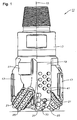
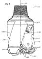
- Bit 11 comprises a bit body 13 having a central longitudinal axis 15 that defines an axial center of the bit body 13.
- the bit body 13 is steel, but could also be formed of matrix material with steel reinforcements, or of a sintered carbide material.
- Bit body 13 includes a shank at the upper or trailing end thereof threaded or otherwise configured for attachment to a hollow drillstring (not shown), which rotates bit 11 and provides pressurized drilling fluid to the bit and the formation being drilled.
- bit leg 17 extends downwardly from the bit body 13 in the axial direction.
- the bit body 13 also has a plurality (e.g., also two shown) of fixed blades 19 that extend downwardly in the axial direction.
- the number of bit legs 17 and fixed blades 19 is at least one but may be more than two.
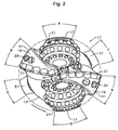
- bit legs 17 (and the associated rolling cutters) are not directly opposite one another (are about 191 degrees apart measured in the direction of rotation of bit 11), nor are fixed blades 19 (which are about 169 degrees apart measured in the direction of rotation of bit 11). Other spacings and distributions of legs 17 and blades 19 may be appropriate.
- a rolling cutter 21 is mounted on a sealed journal bearing that is part of each bit leg 17. According to the illustrated embodiment, the rotational axis of each rolling cutter 21 intersects the axial center 15 of the bit. Unsealed journal or sealed or unsealed rolling-element bearings may be employed in addition to the sealed journal bearing.
- each rolling cutter 21 (typically called the gage cutter surface in conventional rolling cutter bits), is spaced slightly radially inward from the outermost gage surface of bit body 13, but the radially outermost surfaces of the bit legs may extend to full gage diameter (typically within 0.127-0.635 cm (0.050-0.250 inch) of full gage diameter), so that the bit legs contact the sidewall of the borehole during drilling operation to assist in stabilizing the bit during drilling operation.
- the radially outermost surface of each bit leg 17 may also be recessed from the full gage diameter, in which case less or no stabilization is effected.
- rolling cutters 21 have no skew or angle and no offset, so that the axis of rotation of each rolling cutter 21 intersects the axial center (central axis) 15 of the bit body 13.
- the rolling cutters 21 may be provided with skew angle and (or) offset to induce sliding of the rolling cutters 21 as they roll over the borehole bottom.
- At least one (a plurality is illustrated) rolling-cutter cutting elements 25 are arranged on the rolling cutters 21 in generally circumferential rows.
- Rolling-cutter cutting elements 25 need not be arranged in rows, but instead could be "randomly” placed on each rolling cutter 21.
- the rolling-cutter cutting elements may take the form of one or more discs or "kerf-rings,” which would also fall within the meaning of the term rolling-cutter cutting elements.
- Tungsten carbide inserts 25 secured by interference fit into bores in the rolling cutter 21 are shown, but a milled- or steel-tooth cutter having hardfaced cutting elements (25) integrally formed with and protruding from the rolling cutter could be used in certain applications and the term "rolling-cutter cutting elements" as used herein encompasses such teeth.
- the inserts or cutting elements may be chisel- shaped as shown, conical, round, or ovoid, or other shapes and combinations of shapes depending upon the application.
- Rolling-cutter cutting elements 25 may also be formed of, or coated with, super-abrasive or super-hard materials such as polycrystalline diamond, cubic boron nitride, and the like.
- a plurality of fixed-blade cutting elements 31 are arranged in a row and secured to each of the fixed blades 19 at the rotationally leading edges thereof (leading being defined in the direction of rotation of bit 11).
- Each of the fixed-blade cutting elements 31 comprises a polycrystalline diamond layer or table on a rotationally leading face of a supporting tungsten carbide substrate, the diamond layer or table providing a cutting face having a cutting edge at a periphery thereof for engaging the formation.
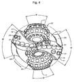
- the radially outermost cutting elements 31 on the radially outermost surface of each of the fixed blades 19 define the bit and borehole diameter (shown in phantom in Figures 2 , 4 and 6 ) drilled by bit 11.
- Each blade may also be provided with back-up cutters 33.
- fixed-blade cutting elements 31 including polycrystalline diamond tables mounted on tungsten carbide substrates
- such term as used herein encompasses thermally stable polycrystalline diamond (TSP) wafers or tables mounted on tungsten carbide substrates, and other, similar super-abrasive or super-hard materials such as cubic boron nitride and diamond-like carbon.
- TSP thermally stable polycrystalline diamond
- Fixed-blade cutting elements 31 may be brazed or otherwise secured in recesses or "pockets" on each blade 19 so that their peripheral or cutting edges on cutting faces are presented to the formation.
- each fixed blade 19 extends to full gage diameter (typically within 0.127-0.635 cm (0.050-0.250 inch) of full gage diameter) and serves as a stabilizer.
- This surface may be provided with a plurality of flat-topped inserts 41 that may or may not be configured with relatively sharp cutting edges. Without sharp cutting edges, inserts 41 serve to resist wear of the upper portion of each fixed blade. With sharp cutting edges, as disclosed in commonly assigned U.S. Patent Nos. 5,287,936 , 5,346,026 , 5,467,836 , 5,655,612 , and 6,050,354 , inserts 41 assist with reaming and maintaining the gage diameter of the borehole.
- Inserts 41 may be formed of tungsten carbide or other hard metal, alone or in combination with polycrystalline or synthetic or natural diamond or other super-abrasive material. Super-abrasive materials are preferred, but not necessary, if inserts 41 are provided with sharp cutting edges for active cutting of the sidewall of the borehole. Inserts may be brazed or interference fit, or otherwise conventionally secured to fixed blades 19 (and may also be provided on the radially outermost surfaces of bit legs 17).
- At least a portion of at least one of the fixed cutting elements 31 is located near or at the axial center 15 of the bit body 13 and thus is positioned to remove formation material at the axial center of the borehole (typically, the axial center of the bit will generally coincide with the center of the borehole being drilled, with some minimal variation due to lateral bit movement during drilling).
- at least one of the fixed cutting elements 31 has its laterally innermost edge tangent or in close proximity to the axial center 15 of the bit 11. While this center-cutting feature is a preferred embodiment, the teachings of the present invention are equally applicable to hybrid bits lacking this feature.
- a stabilizer pad 51, 151 is located on the bit body 13 between each bit leg 17 and fixed blade 19, preferably rotationally leading or ahead of each fixed blade 19 and midway between blade 19 and bit leg 17.
- Each stabilizer pad extends radially outwardly to the full gage diameter (again, typically within 0.127-0.635 cm (0.050-0.250 inch)) of bit 11 to ensure that each pad 51, 151 remains in contact with the sidewall of the borehole during drilling operation to effect stabilization of the bit.
- stabilizer pads 51 are discrete and separate from fixed blade 19 and bit leg 17.
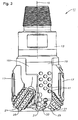
- stabilizer pads 151 are integral with and extend in a rotationally leading direction from each fixed blade 19.
- the term "integral" is intended to encompass any manufacturing process resulting in the structure shown in Figures 3 and 4 .
- the pads could also be multiple discrete pads between bit legs 17 and blades 19.
- Each pad 51, 151 has a borehole sidewall engaging surface formed as described in commonly assigned U.S. Patent No. 5,996,713 to Pessier, et al. Additionally, the area (exposed to the sidewall of the borehole being drilled) of each pad 51, 151 should be equal, so that no single pad has a greater area of contact than any other pad and the pads are therefore less likely to become an instant center of rotation of the bit 11.
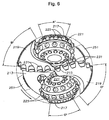
- Figures 5 and 6 illustrate another embodiment of the invention that is generally similar to the embodiments of Figures 1 through 4 (similar structures are numbered similarly, e.g., bit legs 17, 217; blades 19, 219, etc.), except the gage or radially outermost surface of each fixed blade 219 is made wider than typical and, rather than extending axially downward and parallel to the longitudinal axis 215, extends helically or spirally or linearly at an angle relative to (not or non-parallel to) the longitudinal axis 215, i.e., at an angle other than zero.
- Both the leading 219A and trailing edges 219B of the gage surface of each blade 219 extend downwardly at a selected angle (approximately 20 degrees is illustrated in Figure 5 ).
- one of the leading or trailing edges 219A, 219B can extend at an angle or non-parallel to the longitudinal axis, while the other is parallel.
- each blade then operates as a stabilizer pad that describes a much larger segment or angular portion (labeled B" and D") than a "straight" blade that extends downward parallel to the longitudinal axis 215 of bit 211.
- Such a configuration is especially useful when there are relatively few blades 219 and provides stabilization in the area rotationally trailing each blade 219, which can be useful for preventing backward whirl.
- the spiral or angled blade configuration creates large-area stabilizer pads without blocking or impeding the return flow to the same extent as a discrete stabilizer pad of the same area, allowing freer return of drilling fluid and cuttings through the junk slots to the annulus.
- chordal drop is measured by drawing a chord between the leading edge of blade 219 and trailing edge of bit leg 217 (it is a chord of the borehole diameter). The maximum distance between the chord and the gage or borehole diameter, measured perpendicular to the chord, is the chordal drop. It is desirable that chordal drop be minimized and also equal between each bit leg 217 and blade 219.
- a leading stabilization pad 251 shown in phantom in Figure 6
- Such a stabilization pad preferably is separate from the blade 219, but may also be formed integrally, as described above in connection with Figures 3 and 4 .
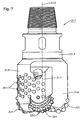
- Figures 7 and 8 disclose another illustrative embodiment in which stabilization is achieved by merging the radially outermost portions of each bit leg (317) with the fixed blade that rotationally leads the leg (similar structures numbered similarly, e.g. bit legs 17, 317; blades 19, 319, etc.).
- the radially outermost surfaces of bit legs 317 and fixed blades 319 are congruent at the gage diameter of the bit and are circumferentially joined or integrally formed so that there is no junk slot formed between the blade 319 and the bit leg 317 that rotationally trails it.
- This merged structure forms a stabilizer pad (not numbered).
- the illustrative embodiment shows two legs 317 (and associated cutters 321, 323) and two blades 319, but bits having more blades and more legs (and associated cutters). However, this embodiment is not as easily adapted to bits having uneven numbers of blades and bit legs (and associated cutters) as are the embodiments of Figures 1 through 6 .
- Each stabilizer pad 51, 151, 251 (and the portions of each bit leg 17, 217, 317 and fixed blade 19, 219, 319 that extend radially outwardly to the full gage diameter of the bit 11) describes a segment or angular portion (A, B, C, D, E, and F, in Figure 2 ; A', B', C', and D' in Figure 4 ; and A", B", C", and D" in Figure 6 ) of the circumference of the borehole being drilled (shown in phantom in Figures 2 and 4 ).
- the size (and number) of pads preferably is selected so that the total segment or angular portion of the bit gage circumference equals or exceeds 180 degrees.
- the invention has several advantages and includes providing a hybrid drill bit that is stable in drilling operation while avoiding off-center running.
- a stable-running bit avoids damage to cutting elements that could cause premature failure of the bit.
Landscapes
- Engineering & Computer Science (AREA)
- Geology (AREA)
- Life Sciences & Earth Sciences (AREA)
- Mining & Mineral Resources (AREA)
- Physics & Mathematics (AREA)
- Environmental & Geological Engineering (AREA)
- Fluid Mechanics (AREA)
- Mechanical Engineering (AREA)
- General Life Sciences & Earth Sciences (AREA)
- Geochemistry & Mineralogy (AREA)
- Earth Drilling (AREA)
- Processing Of Stones Or Stones Resemblance Materials (AREA)
- Drilling Tools (AREA)
Claims (12)
- Un trépan de forage terrestre (11, 211) comprenant :un corps de trépan (13, 213) configuré au niveau de son étendue supérieure pour un raccordement dans un train de tiges,au moins une lame fixe (19, 219) s'étendant vers le bas à partir du corps de trépan (13, 213), la lame fixe (19, 219) possédant un front de taille radialement le plus à l'extérieur,une pluralité d'éléments de coupe fixes (31, 231) fixés à la lame fixe (19,219),au moins une patte de trépan (17, 217) fixée au corps de trépan (13, 213),un dispositif de coupe à molettes (21, 221) monté pour rotation sur la patte de trépan (17, 217), caractérisé parau moins un tampon stabilisateur (51, 151, 251) disposé entre la au moins une patte de trépan (17, 217) et la au moins une lame fixe (19, 219), le tampon stabilisateur (51, 151) s'étendant radialement vers l'extérieur vers sensiblement le front de taille.
- Le trépan de forage terrestre (11, 211) selon la revendication 1, comprenant en outre une pluralité d'éléments de coupe de dispositif de coupe à molettes agencés sur le dispositif de coupe à molettes (21, 221).
- Le trépan de forage terrestre (11, 211) selon la revendication 1, dans lequel le tampon stabilisateur (51, 151, 251) est formé d'un seul tenant avec la lame fixe (19, 219) et s'étend vers la patte de trépan (17, 217).
- Le trépan de forage terrestre (11, 211) selon la revendication 1, dans lequel au moins une partie des éléments de coupe fixes (31, 231) sont agencés en une rangée sur un bord d'attaque rotatif de la lame fixe (19, 219).
- Le trépan de forage terrestre (11, 211) selon la revendication 1, dans lequel le tampon stabilisateur (51, 151, 251), le front de taille de chaque lame fixe (19, 219) et une partie de la patte de trépan (17, 217) s'étendant vers le front de taille décrivent conjointement un segment de la circonférence du trou de forage qui est égal à ou dépasse 180 degrés.
- Le trépan de forage terrestre (11, 211) selon la revendication 1, comprenant en outre :une pluralité de lames fixes (19, 219) s'étendant vers le bas à partir du corps de trépan (13, 213),une pluralité de pattes de trépan (17, 217) s'étendant vers le bas à partir du corps de trépan (13, 213), etun tampon stabilisateur (51, 151, 251) entre chaque patte de trépan (17, 217) et chaque lame fixe (19, 219).
- Le trépan de forage terrestre (11, 211) selon la revendication 1, dans lequel chaque tampon stabilisateur (51, 151, 251) possède une superficie égale exposée à la paroi latérale du trou de forage qui est foré.
- Un trépan de forage terrestre (311) comprenant :un corps de trépan (313) configuré au niveau de son étendue supérieure pour un raccordement dans un train de tiges,au moins une lame fixe (319) s'étendant vers le bas à partir du corps de trépan (313), la lame fixe (319) possédant un front de taille radialement le plus à l'extérieur,une pluralité d'éléments de coupe fixes (331) fixés à chaque lame fixe (319),au moins une patte de trépan (317) fixée au corps de trépan (313),un dispositif de coupe à molettes (321) monté pour rotation sur la patte de trépan (317), et au moins un élément de coupe de dispositif de coupe à molettes agencé sur le dispositif de coupe à molettes (321), caractérisé en ce quela patte de trépan (317) possède une surface radialement la plus extérieure, la surface radialement la plus extérieure de la patte de trépan (317) s'étendant vers et se joignant à la surface radialement la plus extérieure de la lame fixe (319),
- Le trépan de forage terrestre (311) selon la revendication 8, comprenant en outre une pluralité d'éléments de coupe de dispositif de coupe à molettes agencés sur le dispositif de coupe à molettes (321).
- Le trépan de forage terrestre (311) selon la revendication 8, comprenant en outre une pluralité de lames fixes (319) et une pluralité de pattes de trépan (317), le nombre de lames fixes (319) étant égal au nombre de pattes de trépan (317).
- Le trépan de forage terrestre (311) selon la revendication 8, dans lequel au moins une partie des éléments de coupe fixes (331) sont agencés en une rangée sur un bord d'attaque rotatif de la lame fixe (319).
- Le trépan de forage terrestre (311) selon la revendication 8, dans lequel les surfaces radialement les plus extérieures jointes de la lame fixe (319) et la patte de trépan (317) décrivent conjointement un segment de la circonférence du trou de forage qui est égal à ou dépasse 180 degrés.
Applications Claiming Priority (2)
| Application Number | Priority Date | Filing Date | Title |
|---|---|---|---|
| US12/465,377 US8459378B2 (en) | 2009-05-13 | 2009-05-13 | Hybrid drill bit |
| PCT/US2010/033513 WO2010132232A2 (fr) | 2009-05-13 | 2010-05-04 | Trépan hybride |
Publications (3)
| Publication Number | Publication Date |
|---|---|
| EP2430278A2 EP2430278A2 (fr) | 2012-03-21 |
| EP2430278A4 EP2430278A4 (fr) | 2015-04-22 |
| EP2430278B1 true EP2430278B1 (fr) | 2016-11-09 |
Family
ID=43067608
Family Applications (1)
| Application Number | Title | Priority Date | Filing Date |
|---|---|---|---|
| EP10775268.5A Active EP2430278B1 (fr) | 2009-05-13 | 2010-05-04 | Trépan hybride |
Country Status (6)
| Country | Link |
|---|---|
| US (2) | US8459378B2 (fr) |
| EP (1) | EP2430278B1 (fr) |
| PL (1) | PL2430278T3 (fr) |
| RU (1) | RU2564320C2 (fr) |
| SA (1) | SA110310370B1 (fr) |
| WO (1) | WO2010132232A2 (fr) |
Cited By (1)
| Publication number | Priority date | Publication date | Assignee | Title |
|---|---|---|---|---|
| CN110792397A (zh) * | 2019-12-11 | 2020-02-14 | 西南石油大学 | 一种复合钻头 |
Families Citing this family (26)
| Publication number | Priority date | Publication date | Assignee | Title |
|---|---|---|---|---|
| US8678111B2 (en) | 2007-11-16 | 2014-03-25 | Baker Hughes Incorporated | Hybrid drill bit and design method |
| US20090272582A1 (en) * | 2008-05-02 | 2009-11-05 | Baker Hughes Incorporated | Modular hybrid drill bit |
| US8141664B2 (en) * | 2009-03-03 | 2012-03-27 | Baker Hughes Incorporated | Hybrid drill bit with high bearing pin angles |
| US8459378B2 (en) | 2009-05-13 | 2013-06-11 | Baker Hughes Incorporated | Hybrid drill bit |
| US8157026B2 (en) * | 2009-06-18 | 2012-04-17 | Baker Hughes Incorporated | Hybrid bit with variable exposure |
| CA2773897A1 (fr) | 2009-09-16 | 2011-03-24 | Baker Hughes Incorporated | Ensembles de palier en carbone de diamant polycristallin divorces externes pour trepans de forage hybrides |
| US8448724B2 (en) * | 2009-10-06 | 2013-05-28 | Baker Hughes Incorporated | Hole opener with hybrid reaming section |
| US8191635B2 (en) | 2009-10-06 | 2012-06-05 | Baker Hughes Incorporated | Hole opener with hybrid reaming section |
| BR112012033700B1 (pt) | 2010-06-29 | 2019-12-31 | Baker Hughes Inc | brocas de perfuração com características antirrastreamento |
| US8978786B2 (en) | 2010-11-04 | 2015-03-17 | Baker Hughes Incorporated | System and method for adjusting roller cone profile on hybrid bit |
| MX337212B (es) | 2011-02-11 | 2016-02-17 | Baker Hughes Inc | Sistema y metodo para retencion de base en barrenas hibridas. |
| US9782857B2 (en) | 2011-02-11 | 2017-10-10 | Baker Hughes Incorporated | Hybrid drill bit having increased service life |
| SG11201402311VA (en) | 2011-11-15 | 2014-06-27 | Baker Hughes Inc | Hybrid drill bits having increased drilling efficiency |
| US8881848B2 (en) | 2012-05-07 | 2014-11-11 | Ulterra Drilling Technologies, L.P. | Fixed cutter drill bit with rotating cutter disc |
| CN102678055B (zh) * | 2012-05-18 | 2015-10-28 | 西南石油大学 | 一种刮切-冲击复合式钻头 |
| US9376866B2 (en) | 2013-08-23 | 2016-06-28 | Varel International Ind., L.P. | Hybrid rotary cone drill bit |
| SG11201609528QA (en) | 2014-05-23 | 2016-12-29 | Baker Hughes Inc | Hybrid bit with mechanically attached rolling cutter assembly |
| WO2015195244A1 (fr) | 2014-06-18 | 2015-12-23 | Halliburton Energy Services, Inc. | Ensembles d'éléments de roulement |
| US11428050B2 (en) | 2014-10-20 | 2022-08-30 | Baker Hughes Holdings Llc | Reverse circulation hybrid bit |
| WO2017014730A1 (fr) | 2015-07-17 | 2017-01-26 | Halliburton Energy Services, Inc. | Trépan hybride à éléments de coupe à contre-rotation au centre |
| CN109196181A (zh) | 2016-06-17 | 2019-01-11 | 哈里伯顿能源服务公司 | 一半被锁定的滚动元件 |
| WO2018067142A1 (fr) | 2016-10-05 | 2018-04-12 | Halliburton Energy Services, Inc. | Ensemble élément roulant doté d'un dispositif de retenue souple |
| US10907414B2 (en) | 2017-11-09 | 2021-02-02 | Baker Hughes, A Ge Company, Llc | Earth boring tools having fixed blades and varying sized rotatable cutting structures and related methods |
| US10704336B2 (en) * | 2017-11-21 | 2020-07-07 | Baker Hughes, A Ge Company, Llc | Earth boring tools having fixed blades, rotatable cutting structures, and stabilizing structures and related methods |
| CN110685606B (zh) * | 2018-07-05 | 2021-11-26 | 成都海锐能源科技有限公司 | 一种固定切削结构-牙轮复合钻头 |
| RU190616U1 (ru) * | 2019-04-23 | 2019-07-04 | Общество с ограниченной ответственностью Научно-производственное предприятие "БУРИНТЕХ" (ООО НПП "БУРИНТЕХ") | Гибридное буровое долото |
Family Cites Families (263)
| Publication number | Priority date | Publication date | Assignee | Title |
|---|---|---|---|---|
| US3126067A (en) * | 1964-03-24 | Roller bit with inserts | ||
| US3126066A (en) * | 1964-03-24 | Rotary drill bit with wiper blade | ||
| USRE23416E (en) * | 1951-10-16 | Drill | ||
| US930759A (en) * | 1908-11-20 | 1909-08-10 | Howard R Hughes | Drill. |
| US1388424A (en) * | 1919-06-27 | 1921-08-23 | Edward A George | Rotary bit |
| US1394769A (en) * | 1920-05-18 | 1921-10-25 | C E Reed | Drill-head for oil-wells |
| US1519641A (en) * | 1920-10-12 | 1924-12-16 | Walter N Thompson | Rotary underreamer |
| US1537550A (en) | 1923-01-13 | 1925-05-12 | Reed Roller Bit Co | Lubricator for deep-well-drilling apparatus |
| US1821474A (en) * | 1927-12-05 | 1931-09-01 | Sullivan Machinery Co | Boring tool |
| US1896243A (en) * | 1928-04-12 | 1933-02-07 | Hughes Tool Co | Cutter support for well drills |
| US1816568A (en) * | 1929-06-05 | 1931-07-28 | Reed Roller Bit Co | Drill bit |
| US1874066A (en) * | 1930-04-28 | 1932-08-30 | Floyd L Scott | Combination rolling and scraping cutter drill |
| US1932487A (en) * | 1930-07-11 | 1933-10-31 | Hughes Tool Co | Combination scraping and rolling cutter drill |
| US1879127A (en) * | 1930-07-21 | 1932-09-27 | Hughes Tool Co | Combination rolling and scraping cutter bit |
| US2030722A (en) * | 1933-12-01 | 1936-02-11 | Hughes Tool Co | Cutter assembly |
| US2117481A (en) * | 1935-02-19 | 1938-05-17 | Globe Oil Tools Co | Rock core drill head |
| US2119618A (en) * | 1937-08-28 | 1938-06-07 | John A Zublin | Oversize hole drilling mechanism |
| US2198849A (en) * | 1938-06-09 | 1940-04-30 | Reuben L Waxler | Drill |
| US2204657A (en) | 1938-07-12 | 1940-06-18 | Brendel Clyde | Roller bit |
| US2216894A (en) * | 1939-10-12 | 1940-10-08 | Reed Roller Bit Co | Rock bit |
| US2244537A (en) * | 1939-12-22 | 1941-06-03 | Archer W Kammerer | Well drilling bit |
| US2320136A (en) * | 1940-09-30 | 1943-05-25 | Archer W Kammerer | Well drilling bit |
| US2297157A (en) * | 1940-11-16 | 1942-09-29 | Mcclinton John | Drill |
| US2318370A (en) | 1940-12-06 | 1943-05-04 | Kasner M | Oil well drilling bit |
| US2320137A (en) * | 1941-08-12 | 1943-05-25 | Archer W Kammerer | Rotary drill bit |
| US2358642A (en) | 1941-11-08 | 1944-09-19 | Archer W Kammerer | Rotary drill bit |
| US2380112A (en) * | 1942-01-02 | 1945-07-10 | Kinnear Clarence Wellington | Drill |
| US2520517A (en) | 1946-10-25 | 1950-08-29 | Manley L Natland | Apparatus for drilling wells |
| US2557302A (en) | 1947-12-12 | 1951-06-19 | Aubrey F Maydew | Combination drag and rotary drilling bit |
| US2575438A (en) | 1949-09-28 | 1951-11-20 | Kennametal Inc | Percussion drill bit body |
| US2628821A (en) | 1950-10-07 | 1953-02-17 | Kennametal Inc | Percussion drill bit body |
| US2719026A (en) * | 1952-04-28 | 1955-09-27 | Reed Roller Bit Co | Earth boring drill |
| US2815932A (en) * | 1956-02-29 | 1957-12-10 | Norman E Wolfram | Retractable rock drill bit apparatus |
| US2994389A (en) * | 1957-06-07 | 1961-08-01 | Le Bus Royalty Company | Combined drilling and reaming apparatus |
| US3066749A (en) * | 1959-08-10 | 1962-12-04 | Jersey Prod Res Co | Combination drill bit |
| US3010708A (en) * | 1960-04-11 | 1961-11-28 | Goodman Mfg Co | Rotary mining head and core breaker therefor |
| US3050293A (en) * | 1960-05-12 | 1962-08-21 | Goodman Mfg Co | Rotary mining head and core breaker therefor |
| US3055443A (en) * | 1960-05-31 | 1962-09-25 | Jersey Prod Res Co | Drill bit |
| SU145867A1 (ru) * | 1961-07-08 | 1961-11-30 | И.И. Барабашкин | Шарошечное буровое долото с режущими лопаст ми |
| US3239431A (en) * | 1963-02-21 | 1966-03-08 | Knapp Seth Raymond | Rotary well bits |
| US3174564A (en) * | 1963-06-10 | 1965-03-23 | Hughes Tool Co | Combination core bit |
| US3250337A (en) * | 1963-10-29 | 1966-05-10 | Max J Demo | Rotary shock wave drill bit |
| US3269469A (en) * | 1964-01-10 | 1966-08-30 | Hughes Tool Co | Solid head rotary-percussion bit with rolling cutters |
| US3387673A (en) * | 1966-03-15 | 1968-06-11 | Ingersoll Rand Co | Rotary percussion gang drill |
| US3424258A (en) * | 1966-11-16 | 1969-01-28 | Japan Petroleum Dev Corp | Rotary bit for use in rotary drilling |
| DE1301784B (de) | 1968-01-27 | 1969-08-28 | Deutsche Erdoel Ag | Kombinationsbohrmeissel fuer plastisches Gebirge |
| US3583501A (en) * | 1969-03-06 | 1971-06-08 | Mission Mfg Co | Rock bit with powered gauge cutter |
| USRE28625E (en) | 1970-08-03 | 1975-11-25 | Rock drill with increased bearing life | |
| US3760894A (en) | 1971-11-10 | 1973-09-25 | M Pitifer | Replaceable blade drilling bits |
| US4006788A (en) * | 1975-06-11 | 1977-02-08 | Smith International, Inc. | Diamond cutter rock bit with penetration limiting |
| JPS5382601A (en) * | 1976-12-28 | 1978-07-21 | Tokiwa Kogyo Kk | Rotary grinding type excavation drill head |
| US4140189A (en) * | 1977-06-06 | 1979-02-20 | Smith International, Inc. | Rock bit with diamond reamer to maintain gage |
| US4270812A (en) * | 1977-07-08 | 1981-06-02 | Thomas Robert D | Drill bit bearing |
| US4187922A (en) | 1978-05-12 | 1980-02-12 | Dresser Industries, Inc. | Varied pitch rotary rock bit |
| DE2960568D1 (en) | 1978-05-30 | 1981-11-05 | Grootcon Uk Ltd | Method of welding metal parts |
| US4285409A (en) * | 1979-06-28 | 1981-08-25 | Smith International, Inc. | Two cone bit with extended diamond cutters |
| US4527637A (en) * | 1981-05-11 | 1985-07-09 | Bodine Albert G | Cycloidal drill bit |
| US4293048A (en) * | 1980-01-25 | 1981-10-06 | Smith International, Inc. | Jet dual bit |
| US4343371A (en) * | 1980-04-28 | 1982-08-10 | Smith International, Inc. | Hybrid rock bit |
| US4369849A (en) * | 1980-06-05 | 1983-01-25 | Reed Rock Bit Company | Large diameter oil well drilling bit |
| US4359112A (en) * | 1980-06-19 | 1982-11-16 | Smith International, Inc. | Hybrid diamond insert platform locator and retention method |
| US4320808A (en) * | 1980-06-24 | 1982-03-23 | Garrett Wylie P | Rotary drill bit |
| US4386669A (en) * | 1980-12-08 | 1983-06-07 | Evans Robert F | Drill bit with yielding support and force applying structure for abrasion cutting elements |
| US4428687A (en) * | 1981-05-11 | 1984-01-31 | Hughes Tool Company | Floating seal for earth boring bit |
| US4410284A (en) * | 1982-04-22 | 1983-10-18 | Smith International, Inc. | Composite floating element thrust bearing |
| US4527644A (en) | 1983-03-25 | 1985-07-09 | Allam Farouk M | Drilling bit |
| US4444281A (en) * | 1983-03-30 | 1984-04-24 | Reed Rock Bit Company | Combination drag and roller cutter drill bit |
| WO1985002223A1 (fr) | 1983-11-18 | 1985-05-23 | Rock Bit Industries U.S.A., Inc. | Trepan hybride |
| AU3946885A (en) | 1984-03-26 | 1985-10-03 | Norton Christensen Inc. | Cutting element using polycrystalline diamond disks |
| US5028177A (en) | 1984-03-26 | 1991-07-02 | Eastman Christensen Company | Multi-component cutting element using triangular, rectangular and higher order polyhedral-shaped polycrystalline diamond disks |
| US4726718A (en) * | 1984-03-26 | 1988-02-23 | Eastman Christensen Co. | Multi-component cutting element using triangular, rectangular and higher order polyhedral-shaped polycrystalline diamond disks |
| US4572306A (en) * | 1984-12-07 | 1986-02-25 | Dorosz Dennis D E | Journal bushing drill bit construction |
| US4738322A (en) * | 1984-12-21 | 1988-04-19 | Smith International Inc. | Polycrystalline diamond bearing system for a roller cone rock bit |
| US4657091A (en) * | 1985-05-06 | 1987-04-14 | Robert Higdon | Drill bits with cone retention means |
| SU1331988A1 (ru) | 1985-07-12 | 1987-08-23 | И.И. Барабашкин, И. В. Воевидко и В. М. Ивасив | Калибратор |
| US4664705A (en) * | 1985-07-30 | 1987-05-12 | Sii Megadiamond, Inc. | Infiltrated thermally stable polycrystalline diamond |
| GB8528894D0 (en) | 1985-11-23 | 1986-01-02 | Nl Petroleum Prod | Rotary drill bits |
| US4690228A (en) * | 1986-03-14 | 1987-09-01 | Eastman Christensen Company | Changeover bit for extended life, varied formations and steady wear |
| US4706765A (en) * | 1986-08-11 | 1987-11-17 | Four E Inc. | Drill bit assembly |
| US4943488A (en) | 1986-10-20 | 1990-07-24 | Norton Company | Low pressure bonding of PCD bodies and method for drill bits and the like |
| US5030276A (en) | 1986-10-20 | 1991-07-09 | Norton Company | Low pressure bonding of PCD bodies and method |
| US5116568A (en) | 1986-10-20 | 1992-05-26 | Norton Company | Method for low pressure bonding of PCD bodies |
| US4727942A (en) * | 1986-11-05 | 1988-03-01 | Hughes Tool Company | Compensator for earth boring bits |
| US4765205A (en) * | 1987-06-01 | 1988-08-23 | Bob Higdon | Method of assembling drill bits and product assembled thereby |
| CA1270479A (fr) * | 1987-12-14 | 1990-06-19 | Jerome Labrosse | Outil de forage pour l'implantation de tubages |
| USRE37450E1 (en) | 1988-06-27 | 2001-11-20 | The Charles Machine Works, Inc. | Directional multi-blade boring head |
| US5027912A (en) | 1988-07-06 | 1991-07-02 | Baker Hughes Incorporated | Drill bit having improved cutter configuration |
| US4874047A (en) * | 1988-07-21 | 1989-10-17 | Cummins Engine Company, Inc. | Method and apparatus for retaining roller cone of drill bit |
| US4875532A (en) * | 1988-09-19 | 1989-10-24 | Dresser Industries, Inc. | Roller drill bit having radial-thrust pilot bushing incorporating anti-galling material |
| US4892159A (en) * | 1988-11-29 | 1990-01-09 | Exxon Production Research Company | Kerf-cutting apparatus and method for improved drilling rates |
| NO169735C (no) | 1989-01-26 | 1992-07-29 | Geir Tandberg | Kombinasjonsborekrone |
| GB8907618D0 (en) | 1989-04-05 | 1989-05-17 | Morrison Pumps Sa | Drilling |
| US4932484A (en) * | 1989-04-10 | 1990-06-12 | Amoco Corporation | Whirl resistant bit |
| US4953641A (en) | 1989-04-27 | 1990-09-04 | Hughes Tool Company | Two cone bit with non-opposite cones |
| US4936398A (en) | 1989-07-07 | 1990-06-26 | Cledisc International B.V. | Rotary drilling device |
| US4976324A (en) * | 1989-09-22 | 1990-12-11 | Baker Hughes Incorporated | Drill bit having diamond film cutting surface |
| US5049164A (en) | 1990-01-05 | 1991-09-17 | Norton Company | Multilayer coated abrasive element for bonding to a backing |
| US4991671A (en) | 1990-03-13 | 1991-02-12 | Camco International Inc. | Means for mounting a roller cutter on a drill bit |
| US4984643A (en) | 1990-03-21 | 1991-01-15 | Hughes Tool Company | Anti-balling earth boring bit |
| US5224560A (en) | 1990-10-30 | 1993-07-06 | Modular Engineering | Modular drill bit |
| US5145017A (en) | 1991-01-07 | 1992-09-08 | Exxon Production Research Company | Kerf-cutting apparatus for increased drilling rates |
| US5941322A (en) | 1991-10-21 | 1999-08-24 | The Charles Machine Works, Inc. | Directional boring head with blade assembly |
| US5238074A (en) | 1992-01-06 | 1993-08-24 | Baker Hughes Incorporated | Mosaic diamond drag bit cutter having a nonuniform wear pattern |
| US5287936A (en) | 1992-01-31 | 1994-02-22 | Baker Hughes Incorporated | Rolling cone bit with shear cutting gage |
| US5467836A (en) | 1992-01-31 | 1995-11-21 | Baker Hughes Incorporated | Fixed cutter bit with shear cutting gage |
| US5346026A (en) | 1992-01-31 | 1994-09-13 | Baker Hughes Incorporated | Rolling cone bit with shear cutting gage |
| NO176528C (no) | 1992-02-17 | 1995-04-19 | Kverneland Klepp As | Anordning ved borekroner |
| EP0569663A1 (fr) | 1992-05-15 | 1993-11-18 | Baker Hughes Incorporated | Trépan amélioré anti-tourbillon |
| US5558170A (en) | 1992-12-23 | 1996-09-24 | Baroid Technology, Inc. | Method and apparatus for improving drill bit stability |
| US5289889A (en) | 1993-01-21 | 1994-03-01 | Marvin Gearhart | Roller cone core bit with spiral stabilizers |
| US5560440A (en) | 1993-02-12 | 1996-10-01 | Baker Hughes Incorporated | Bit for subterranean drilling fabricated from separately-formed major components |
| US5361859A (en) | 1993-02-12 | 1994-11-08 | Baker Hughes Incorporated | Expandable gage bit for drilling and method of drilling |
| US5355559A (en) | 1993-04-26 | 1994-10-18 | Amerock Corporation | Hinge for inset doors |
| US5351770A (en) * | 1993-06-15 | 1994-10-04 | Smith International, Inc. | Ultra hard insert cutters for heel row rotary cone rock bit applications |
| US5429200A (en) | 1994-03-31 | 1995-07-04 | Dresser Industries, Inc. | Rotary drill bit with improved cutter |
| US5452771A (en) | 1994-03-31 | 1995-09-26 | Dresser Industries, Inc. | Rotary drill bit with improved cutter and seal protection |
| US5472057A (en) | 1994-04-11 | 1995-12-05 | Atlantic Richfield Company | Drilling with casing and retrievable bit-motor assembly |
| US5606895A (en) | 1994-08-08 | 1997-03-04 | Dresser Industries, Inc. | Method for manufacture and rebuild a rotary drill bit |
| US5439068B1 (en) | 1994-08-08 | 1997-01-14 | Dresser Ind | Modular rotary drill bit |
| US5513715A (en) | 1994-08-31 | 1996-05-07 | Dresser Industries, Inc. | Flat seal for a roller cone rock bit |
| US5553681A (en) | 1994-12-07 | 1996-09-10 | Dresser Industries, Inc. | Rotary cone drill bit with angled ramps |
| US5547033A (en) | 1994-12-07 | 1996-08-20 | Dresser Industries, Inc. | Rotary cone drill bit and method for enhanced lifting of fluids and cuttings |
| US5755297A (en) | 1994-12-07 | 1998-05-26 | Dresser Industries, Inc. | Rotary cone drill bit with integral stabilizers |
| US5593231A (en) | 1995-01-17 | 1997-01-14 | Dresser Industries, Inc. | Hydrodynamic bearing |
| US5996713A (en) | 1995-01-26 | 1999-12-07 | Baker Hughes Incorporated | Rolling cutter bit with improved rotational stabilization |
| US5570750A (en) | 1995-04-20 | 1996-11-05 | Dresser Industries, Inc. | Rotary drill bit with improved shirttail and seal protection |
| US5641029A (en) | 1995-06-06 | 1997-06-24 | Dresser Industries, Inc. | Rotary cone drill bit modular arm |
| US5695019A (en) * | 1995-08-23 | 1997-12-09 | Dresser Industries, Inc. | Rotary cone drill bit with truncated rolling cone cutters and dome area cutter inserts |
| USD384084S (en) | 1995-09-12 | 1997-09-23 | Dresser Industries, Inc. | Rotary cone drill bit |
| US5695018A (en) | 1995-09-13 | 1997-12-09 | Baker Hughes Incorporated | Earth-boring bit with negative offset and inverted gage cutting elements |
| US5904213A (en) | 1995-10-10 | 1999-05-18 | Camco International (Uk) Limited | Rotary drill bits |
| US5862871A (en) | 1996-02-20 | 1999-01-26 | Ccore Technology & Licensing Limited, A Texas Limited Partnership | Axial-vortex jet drilling system and method |
| AU726959B2 (en) | 1996-03-01 | 2000-11-30 | Tiger 19 Partners, Ltd | Cantilevered hole opener |
| US5642942A (en) | 1996-03-26 | 1997-07-01 | Smith International, Inc. | Thrust plugs for rotary cone air bits |
| US6390210B1 (en) | 1996-04-10 | 2002-05-21 | Smith International, Inc. | Rolling cone bit with gage and off-gage cutter elements positioned to separate sidewall and bottom hole cutting duty |
| US6241034B1 (en) * | 1996-06-21 | 2001-06-05 | Smith International, Inc. | Cutter element with expanded crest geometry |
| US6116357A (en) | 1996-09-09 | 2000-09-12 | Smith International, Inc. | Rock drill bit with back-reaming protection |
| US5904212A (en) | 1996-11-12 | 1999-05-18 | Dresser Industries, Inc. | Gauge face inlay for bit hardfacing |
| BE1010802A3 (fr) | 1996-12-16 | 1999-02-02 | Dresser Ind | Tete de forage. |
| BE1010801A3 (fr) | 1996-12-16 | 1999-02-02 | Dresser Ind | Outil de forage et/ou de carottage. |
| GB9708428D0 (en) | 1997-04-26 | 1997-06-18 | Camco Int Uk Ltd | Improvements in or relating to rotary drill bits |
| US5944125A (en) | 1997-06-19 | 1999-08-31 | Varel International, Inc. | Rock bit with improved thrust face |
| US6095265A (en) | 1997-08-15 | 2000-08-01 | Smith International, Inc. | Impregnated drill bits with adaptive matrix |
| US6561293B2 (en) * | 1997-09-04 | 2003-05-13 | Smith International, Inc. | Cutter element with non-linear, expanded crest |
| US6321862B1 (en) * | 1997-09-08 | 2001-11-27 | Baker Hughes Incorporated | Rotary drill bits for directional drilling employing tandem gage pad arrangement with cutting elements and up-drill capability |
| US6173797B1 (en) | 1997-09-08 | 2001-01-16 | Baker Hughes Incorporated | Rotary drill bits for directional drilling employing movable cutters and tandem gage pad arrangement with active cutting elements and having up-drill capability |
| US6220374B1 (en) | 1998-01-26 | 2001-04-24 | Dresser Industries, Inc. | Rotary cone drill bit with enhanced thrust bearing flange |
| WO1999037879A1 (fr) | 1998-01-26 | 1999-07-29 | Dresser Industries, Inc. | Trepan a cone rotatif a coussinet ameliore |
| US6568490B1 (en) | 1998-02-23 | 2003-05-27 | Halliburton Energy Services, Inc. | Method and apparatus for fabricating rotary cone drill bits |
| US6109375A (en) | 1998-02-23 | 2000-08-29 | Dresser Industries, Inc. | Method and apparatus for fabricating rotary cone drill bits |
| EP1066447B1 (fr) | 1998-03-26 | 2004-08-18 | Halliburton Energy Services, Inc. | Outil de forage a cones rotatifs equipe d'un systeme de roulement ameliore |
| JP2000080878A (ja) | 1998-06-30 | 2000-03-21 | Kyoei Kogyo Kk | 硬軟地層兼用型掘削用ヘッド |
| US6206116B1 (en) | 1998-07-13 | 2001-03-27 | Dresser Industries, Inc. | Rotary cone drill bit with machined cutting structure |
| US20040045742A1 (en) | 2001-04-10 | 2004-03-11 | Halliburton Energy Services, Inc. | Force-balanced roller-cone bits, systems, drilling methods, and design methods |
| US6241036B1 (en) | 1998-09-16 | 2001-06-05 | Baker Hughes Incorporated | Reinforced abrasive-impregnated cutting elements, drill bits including same |
| US6345673B1 (en) | 1998-11-20 | 2002-02-12 | Smith International, Inc. | High offset bits with super-abrasive cutters |
| US6401844B1 (en) | 1998-12-03 | 2002-06-11 | Baker Hughes Incorporated | Cutter with complex superabrasive geometry and drill bits so equipped |
| SE516079C2 (sv) * | 1998-12-18 | 2001-11-12 | Sandvik Ab | Rullborrkrona |
| US6279671B1 (en) | 1999-03-01 | 2001-08-28 | Amiya K. Panigrahi | Roller cone bit with improved seal gland design |
| BE1012545A3 (fr) | 1999-03-09 | 2000-12-05 | Security Dbs | Elargisseur de trou de forage. |
| CA2342615C (fr) | 1999-05-14 | 2007-05-01 | Allen Kent Rives | Elargisseur muni de bras et de fraises de tailles multiples remplacables |
| CA2314114C (fr) | 1999-07-19 | 2007-04-10 | Smith International, Inc. | Fleuret de perforatrice ameliore avec protection de la colonne |
| US6684967B2 (en) | 1999-08-05 | 2004-02-03 | Smith International, Inc. | Side cutting gage pad improving stabilization and borehole integrity |
| US6460631B2 (en) | 1999-08-26 | 2002-10-08 | Baker Hughes Incorporated | Drill bits with reduced exposure of cutters |
| US6533051B1 (en) | 1999-09-07 | 2003-03-18 | Smith International, Inc. | Roller cone drill bit shale diverter |
| US6386302B1 (en) | 1999-09-09 | 2002-05-14 | Smith International, Inc. | Polycrystaline diamond compact insert reaming tool |
| SE524046C2 (sv) | 1999-09-24 | 2004-06-22 | Varel Internat Inc | Rullborrkrona |
| US6460635B1 (en) * | 1999-10-25 | 2002-10-08 | Kalsi Engineering, Inc. | Load responsive hydrodynamic bearing |
| US6843333B2 (en) | 1999-11-29 | 2005-01-18 | Baker Hughes Incorporated | Impregnated rotary drag bit |
| US6510906B1 (en) | 1999-11-29 | 2003-01-28 | Baker Hughes Incorporated | Impregnated bit with PDC cutters in cone area |
| JP3513698B2 (ja) | 1999-12-03 | 2004-03-31 | 飛島建設株式会社 | 掘削ヘッド |
| US8082134B2 (en) | 2000-03-13 | 2011-12-20 | Smith International, Inc. | Techniques for modeling/simulating, designing optimizing, and displaying hybrid drill bits |
| US6439326B1 (en) | 2000-04-10 | 2002-08-27 | Smith International, Inc. | Centered-leg roller cone drill bit |
| US6688410B1 (en) * | 2000-06-07 | 2004-02-10 | Smith International, Inc. | Hydro-lifter rock bit with PDC inserts |
| US6405811B1 (en) | 2000-09-18 | 2002-06-18 | Baker Hughes Corporation | Solid lubricant for air cooled drill bit and method of drilling |
| US6386300B1 (en) | 2000-09-19 | 2002-05-14 | Curlett Family Limited Partnership | Formation cutting method and system |
| DE60140617D1 (de) | 2000-09-20 | 2010-01-07 | Camco Int Uk Ltd | Polykristalliner diamant mit einer an katalysatormaterial abgereicherten oberfläche |
| US6592985B2 (en) | 2000-09-20 | 2003-07-15 | Camco International (Uk) Limited | Polycrystalline diamond partially depleted of catalyzing material |
| US6408958B1 (en) | 2000-10-23 | 2002-06-25 | Baker Hughes Incorporated | Superabrasive cutting assemblies including cutters of varying orientations and drill bits so equipped |
| GB0102160D0 (en) * | 2001-01-27 | 2001-03-14 | Schlumberger Holdings | Cutting structure for earth boring drill bits |
| CA2371740C (fr) | 2001-02-13 | 2006-04-18 | Smith International, Inc. | Outil de retro-alesage |
| US7137460B2 (en) | 2001-02-13 | 2006-11-21 | Smith International, Inc. | Back reaming tool |
| RU2303689C2 (ru) * | 2001-07-06 | 2007-07-27 | Шелл Интернэшнл Рисерч Маатсхаппий Б.В. | Долото для бурения скважины |
| WO2003010410A1 (fr) * | 2001-07-23 | 2003-02-06 | Shell Internationale Research Maatschappij B.V. | Injection de liquide dans un trou de forage en amont du trepan |
| US6745858B1 (en) | 2001-08-24 | 2004-06-08 | Rock Bit International | Adjustable earth boring device |
| US6601661B2 (en) | 2001-09-17 | 2003-08-05 | Baker Hughes Incorporated | Secondary cutting structure |
| US6742607B2 (en) | 2002-05-28 | 2004-06-01 | Smith International, Inc. | Fixed blade fixed cutter hole opener |
| US6823951B2 (en) * | 2002-07-03 | 2004-11-30 | Smith International, Inc. | Arcuate-shaped inserts for drill bits |
| US6902014B1 (en) | 2002-08-01 | 2005-06-07 | Rock Bit L.P. | Roller cone bi-center bit |
| US6883623B2 (en) | 2002-10-09 | 2005-04-26 | Baker Hughes Incorporated | Earth boring apparatus and method offering improved gage trimmer protection |
| US6913098B2 (en) * | 2002-11-21 | 2005-07-05 | Reedeycalog, L.P. | Sub-reamer for bi-center type tools |
| US7234550B2 (en) | 2003-02-12 | 2007-06-26 | Smith International, Inc. | Bits and cutting structures |
| US20060032677A1 (en) | 2003-02-12 | 2006-02-16 | Smith International, Inc. | Novel bits and cutting structures |
| US20040156676A1 (en) * | 2003-02-12 | 2004-08-12 | Brent Boudreaux | Fastener for variable mounting |
| US6904984B1 (en) | 2003-06-20 | 2005-06-14 | Rock Bit L.P. | Stepped polycrystalline diamond compact insert |
| US7011170B2 (en) | 2003-10-22 | 2006-03-14 | Baker Hughes Incorporated | Increased projection for compacts of a rolling cone drill bit |
| US7395882B2 (en) | 2004-02-19 | 2008-07-08 | Baker Hughes Incorporated | Casing and liner drilling bits |
| US7070011B2 (en) | 2003-11-17 | 2006-07-04 | Baker Hughes Incorporated | Steel body rotary drill bits including support elements affixed to the bit body at least partially defining cutter pocket recesses |
| CA2489187C (fr) | 2003-12-05 | 2012-08-28 | Smith International, Inc. | Materiaux de type diamant polycristallins thermostables et briquettes |
| US20050178587A1 (en) | 2004-01-23 | 2005-08-18 | Witman George B.Iv | Cutting structure for single roller cone drill bit |
| US7195086B2 (en) | 2004-01-30 | 2007-03-27 | Anna Victorovna Aaron | Anti-tracking earth boring bit with selected varied pitch for overbreak optimization and vibration reduction |
| US7647993B2 (en) | 2004-05-06 | 2010-01-19 | Smith International, Inc. | Thermally stable diamond bonded materials and compacts |
| GB2417966A (en) | 2004-08-16 | 2006-03-15 | Halliburton Energy Serv Inc | Roller cone drill bits with optimized bearing structure |
| US7754333B2 (en) | 2004-09-21 | 2010-07-13 | Smith International, Inc. | Thermally stable diamond polycrystalline diamond constructions |
| GB0423597D0 (en) | 2004-10-23 | 2004-11-24 | Reedhycalog Uk Ltd | Dual-edge working surfaces for polycrystalline diamond cutting elements |
| US7350601B2 (en) | 2005-01-25 | 2008-04-01 | Smith International, Inc. | Cutting elements formed from ultra hard materials having an enhanced construction |
| US7435478B2 (en) | 2005-01-27 | 2008-10-14 | Smith International, Inc. | Cutting structures |
| US7533740B2 (en) | 2005-02-08 | 2009-05-19 | Smith International Inc. | Thermally stable polycrystalline diamond cutting elements and bits incorporating the same |
| US7350568B2 (en) | 2005-02-09 | 2008-04-01 | Halliburton Energy Services, Inc. | Logging a well |
| US20060196699A1 (en) | 2005-03-04 | 2006-09-07 | Roy Estes | Modular kerfing drill bit |
| US7472764B2 (en) | 2005-03-25 | 2009-01-06 | Baker Hughes Incorporated | Rotary drill bit shank, rotary drill bits so equipped, and methods of manufacture |
| US7487849B2 (en) | 2005-05-16 | 2009-02-10 | Radtke Robert P | Thermally stable diamond brazing |
| US7493973B2 (en) | 2005-05-26 | 2009-02-24 | Smith International, Inc. | Polycrystalline diamond materials having improved abrasion resistance, thermal stability and impact resistance |
| US7377341B2 (en) | 2005-05-26 | 2008-05-27 | Smith International, Inc. | Thermally stable ultra-hard material compact construction |
| US20060278442A1 (en) | 2005-06-13 | 2006-12-14 | Kristensen Henry L | Drill bit |
| US7320375B2 (en) | 2005-07-19 | 2008-01-22 | Smith International, Inc. | Split cone bit |
| US7462003B2 (en) | 2005-08-03 | 2008-12-09 | Smith International, Inc. | Polycrystalline diamond composite constructions comprising thermally stable diamond volume |
| US7416036B2 (en) | 2005-08-12 | 2008-08-26 | Baker Hughes Incorporated | Latchable reaming bit |
| US9574405B2 (en) | 2005-09-21 | 2017-02-21 | Smith International, Inc. | Hybrid disc bit with optimized PDC cutter placement |
| US7726421B2 (en) | 2005-10-12 | 2010-06-01 | Smith International, Inc. | Diamond-bonded bodies and compacts with improved thermal stability and mechanical strength |
| US7152702B1 (en) | 2005-11-04 | 2006-12-26 | Smith International, Inc. | Modular system for a back reamer and method |
| US7802495B2 (en) * | 2005-11-10 | 2010-09-28 | Baker Hughes Incorporated | Methods of forming earth-boring rotary drill bits |
| US7270196B2 (en) | 2005-11-21 | 2007-09-18 | Hall David R | Drill bit assembly |
| US7484576B2 (en) * | 2006-03-23 | 2009-02-03 | Hall David R | Jack element in communication with an electric motor and or generator |
| US7398837B2 (en) | 2005-11-21 | 2008-07-15 | Hall David R | Drill bit assembly with a logging device |
| US7392862B2 (en) | 2006-01-06 | 2008-07-01 | Baker Hughes Incorporated | Seal insert ring for roller cone bits |
| US7628234B2 (en) | 2006-02-09 | 2009-12-08 | Smith International, Inc. | Thermally stable ultra-hard polycrystalline materials and compacts |
| GB2453875C (en) * | 2006-10-02 | 2009-09-16 | Smith International | Drill bits with dropping tendencies |
| US7387177B2 (en) | 2006-10-18 | 2008-06-17 | Baker Hughes Incorporated | Bearing insert sleeve for roller cone bit |
| US8034136B2 (en) | 2006-11-20 | 2011-10-11 | Us Synthetic Corporation | Methods of fabricating superabrasive articles |
| US7845435B2 (en) * | 2007-04-05 | 2010-12-07 | Baker Hughes Incorporated | Hybrid drill bit and method of drilling |
| US7841426B2 (en) | 2007-04-05 | 2010-11-30 | Baker Hughes Incorporated | Hybrid drill bit with fixed cutters as the sole cutting elements in the axial center of the drill bit |
| US7703557B2 (en) * | 2007-06-11 | 2010-04-27 | Smith International, Inc. | Fixed cutter bit with backup cutter elements on primary blades |
| US7847437B2 (en) * | 2007-07-30 | 2010-12-07 | Gm Global Technology Operations, Inc. | Efficient operating point for double-ended inverter system |
| US7836975B2 (en) | 2007-10-24 | 2010-11-23 | Schlumberger Technology Corporation | Morphable bit |
| US9085939B2 (en) * | 2007-11-14 | 2015-07-21 | Baker Hughes Incorporated | Earth-boring tools attachable to a casing string and methods for their manufacture |
| US8678111B2 (en) | 2007-11-16 | 2014-03-25 | Baker Hughes Incorporated | Hybrid drill bit and design method |
| US7938204B2 (en) | 2007-12-21 | 2011-05-10 | Baker Hughes Incorporated | Reamer with improved hydraulics for use in a wellbore |
| US20090172172A1 (en) | 2007-12-21 | 2009-07-02 | Erik Lambert Graham | Systems and methods for enabling peer-to-peer communication among visitors to a common website |
| SA108290832B1 (ar) | 2007-12-21 | 2012-06-05 | بيكر هوغيس انكوربوريتد | مثقاب ذو أذرع توازن يستخدم في حفر الآبار |
| US20090272582A1 (en) * | 2008-05-02 | 2009-11-05 | Baker Hughes Incorporated | Modular hybrid drill bit |
| US7703556B2 (en) * | 2008-06-04 | 2010-04-27 | Baker Hughes Incorporated | Methods of attaching a shank to a body of an earth-boring tool including a load-bearing joint and tools formed by such methods |
| US7819208B2 (en) * | 2008-07-25 | 2010-10-26 | Baker Hughes Incorporated | Dynamically stable hybrid drill bit |
| US7621346B1 (en) * | 2008-09-26 | 2009-11-24 | Baker Hughes Incorporated | Hydrostatic bearing |
| US7992658B2 (en) | 2008-11-11 | 2011-08-09 | Baker Hughes Incorporated | Pilot reamer with composite framework |
| US7845437B2 (en) * | 2009-02-13 | 2010-12-07 | Century Products, Inc. | Hole opener assembly and a cone arm forming a part thereof |
| US8141664B2 (en) * | 2009-03-03 | 2012-03-27 | Baker Hughes Incorporated | Hybrid drill bit with high bearing pin angles |
| US8056651B2 (en) * | 2009-04-28 | 2011-11-15 | Baker Hughes Incorporated | Adaptive control concept for hybrid PDC/roller cone bits |
| HUE041482T2 (hu) | 2009-05-08 | 2019-05-28 | Transco Mfg Australia Pty Ltd | Fúróberendezés és a hozzávaló felerõsítõ eszköz |
| US8459378B2 (en) | 2009-05-13 | 2013-06-11 | Baker Hughes Incorporated | Hybrid drill bit |
| KR101666947B1 (ko) | 2009-05-20 | 2016-10-17 | 스미스 인터내셔널 인크. | 절삭 요소, 절삭 요소의 제조 방법 및, 절삭 요소를 포함하는 공구 |
| US8157026B2 (en) * | 2009-06-18 | 2012-04-17 | Baker Hughes Incorporated | Hybrid bit with variable exposure |
| US8302709B2 (en) | 2009-06-22 | 2012-11-06 | Sandvik Intellectual Property Ab | Downhole tool leg retention methods and apparatus |
| US8672060B2 (en) | 2009-07-31 | 2014-03-18 | Smith International, Inc. | High shear roller cone drill bits |
| JP2011059289A (ja) | 2009-09-09 | 2011-03-24 | Kyocera Mita Corp | 画像形成装置 |
| US8448724B2 (en) * | 2009-10-06 | 2013-05-28 | Baker Hughes Incorporated | Hole opener with hybrid reaming section |
| US8191635B2 (en) * | 2009-10-06 | 2012-06-05 | Baker Hughes Incorporated | Hole opener with hybrid reaming section |
| AU2010307012A1 (en) | 2009-10-12 | 2012-05-03 | Atlas Copco Secoroc Llc | Downhole tool |
| WO2011084944A2 (fr) | 2010-01-05 | 2011-07-14 | Smith International, Inc. | Trépan à molettes et hybride p.d.c. à cisaillement élevé |
| BR112012033700B1 (pt) | 2010-06-29 | 2019-12-31 | Baker Hughes Inc | brocas de perfuração com características antirrastreamento |
| US9782857B2 (en) | 2011-02-11 | 2017-10-10 | Baker Hughes Incorporated | Hybrid drill bit having increased service life |
| MX337212B (es) | 2011-02-11 | 2016-02-17 | Baker Hughes Inc | Sistema y metodo para retencion de base en barrenas hibridas. |
| WO2015102891A1 (fr) | 2013-12-31 | 2015-07-09 | Smith International, Inc. | Procédé de fabrication de corps à pièces multiples de trépan hybride |
-
2009
- 2009-05-13 US US12/465,377 patent/US8459378B2/en active Active
-
2010
- 2010-05-04 RU RU2011150629/03A patent/RU2564320C2/ru active
- 2010-05-04 WO PCT/US2010/033513 patent/WO2010132232A2/fr active Application Filing
- 2010-05-04 PL PL10775268T patent/PL2430278T3/pl unknown
- 2010-05-04 EP EP10775268.5A patent/EP2430278B1/fr active Active
- 2010-05-11 SA SA110310370A patent/SA110310370B1/ar unknown
-
2013
- 2013-05-30 US US13/905,396 patent/US9670736B2/en active Active
Cited By (1)
| Publication number | Priority date | Publication date | Assignee | Title |
|---|---|---|---|---|
| CN110792397A (zh) * | 2019-12-11 | 2020-02-14 | 西南石油大学 | 一种复合钻头 |
Also Published As
| Publication number | Publication date |
|---|---|
| WO2010132232A2 (fr) | 2010-11-18 |
| RU2564320C2 (ru) | 2015-09-27 |
| RU2011150629A (ru) | 2013-06-20 |
| PL2430278T3 (pl) | 2017-09-29 |
| WO2010132232A4 (fr) | 2011-05-05 |
| SA110310370B1 (ar) | 2014-09-10 |
| US8459378B2 (en) | 2013-06-11 |
| WO2010132232A3 (fr) | 2011-03-03 |
| US20100288561A1 (en) | 2010-11-18 |
| US9670736B2 (en) | 2017-06-06 |
| EP2430278A4 (fr) | 2015-04-22 |
| EP2430278A2 (fr) | 2012-03-21 |
| US20140151131A1 (en) | 2014-06-05 |
Similar Documents
| Publication | Publication Date | Title |
|---|---|---|
| EP2430278B1 (fr) | Trépan hybride | |
| EP2318637B1 (fr) | Trépan hybride dynamiquement stable | |
| US10871036B2 (en) | Hybrid drill bit and design method | |
| EP2156002B1 (fr) | Outil de forage et procédé de forage | |
| EP2370659B1 (fr) | Trépan hybride ayant des systèmes secondaires de découpe de secours, positionnés selon des angles d'inclinaison latéraux élevés | |
| CA2826939C (fr) | Trepan hybride d'entaillage et autres outils de coupe de fond de trou | |
| US8881848B2 (en) | Fixed cutter drill bit with rotating cutter disc | |
| US20100025119A1 (en) | Hybrid drill bit and method of using tsp or mosaic cutters on a hybrid bit | |
| US9284786B2 (en) | Drill bits having depth of cut control features and methods of making and using the same | |
| US9284785B2 (en) | Drill bits having depth of cut control features and methods of making and using the same | |
| EP2222932B1 (fr) | Trépan hybride et son procédé de conception |
Legal Events
| Date | Code | Title | Description |
|---|---|---|---|
| PUAI | Public reference made under article 153(3) epc to a published international application that has entered the european phase |
Free format text: ORIGINAL CODE: 0009012 |
|
| 17P | Request for examination filed |
Effective date: 20111213 |
|
| AK | Designated contracting states |
Kind code of ref document: A2 Designated state(s): AL AT BE BG CH CY CZ DE DK EE ES FI FR GB GR HR HU IE IS IT LI LT LU LV MC MK MT NL NO PL PT RO SE SI SK SM TR |
|
| DAX | Request for extension of the european patent (deleted) | ||
| A4 | Supplementary search report drawn up and despatched |
Effective date: 20150325 |
|
| RIC1 | Information provided on ipc code assigned before grant |
Ipc: E21B 10/62 20060101ALI20150319BHEP Ipc: E21B 10/14 20060101AFI20150319BHEP Ipc: E21B 10/50 20060101ALI20150319BHEP |
|
| GRAP | Despatch of communication of intention to grant a patent |
Free format text: ORIGINAL CODE: EPIDOSNIGR1 |
|
| INTG | Intention to grant announced |
Effective date: 20160603 |
|
| GRAS | Grant fee paid |
Free format text: ORIGINAL CODE: EPIDOSNIGR3 |
|
| GRAA | (expected) grant |
Free format text: ORIGINAL CODE: 0009210 |
|
| AK | Designated contracting states |
Kind code of ref document: B1 Designated state(s): AL AT BE BG CH CY CZ DE DK EE ES FI FR GB GR HR HU IE IS IT LI LT LU LV MC MK MT NL NO PL PT RO SE SI SK SM TR |
|
| REG | Reference to a national code |
Ref country code: GB Ref legal event code: FG4D |
|
| REG | Reference to a national code |
Ref country code: AT Ref legal event code: REF Ref document number: 844104 Country of ref document: AT Kind code of ref document: T Effective date: 20161115 Ref country code: CH Ref legal event code: EP |
|
| REG | Reference to a national code |
Ref country code: IE Ref legal event code: FG4D |
|
| REG | Reference to a national code |
Ref country code: DE Ref legal event code: R096 Ref document number: 602010037882 Country of ref document: DE |
|
| PG25 | Lapsed in a contracting state [announced via postgrant information from national office to epo] |
Ref country code: LV Free format text: LAPSE BECAUSE OF FAILURE TO SUBMIT A TRANSLATION OF THE DESCRIPTION OR TO PAY THE FEE WITHIN THE PRESCRIBED TIME-LIMIT Effective date: 20161109 |
|
| REG | Reference to a national code |
Ref country code: LT Ref legal event code: MG4D |
|
| REG | Reference to a national code |
Ref country code: NO Ref legal event code: T2 Effective date: 20161109 |
|
| REG | Reference to a national code |
Ref country code: NL Ref legal event code: MP Effective date: 20161109 |
|
| REG | Reference to a national code |
Ref country code: AT Ref legal event code: MK05 Ref document number: 844104 Country of ref document: AT Kind code of ref document: T Effective date: 20161109 |
|
| PG25 | Lapsed in a contracting state [announced via postgrant information from national office to epo] |
Ref country code: SE Free format text: LAPSE BECAUSE OF FAILURE TO SUBMIT A TRANSLATION OF THE DESCRIPTION OR TO PAY THE FEE WITHIN THE PRESCRIBED TIME-LIMIT Effective date: 20161109 Ref country code: GR Free format text: LAPSE BECAUSE OF FAILURE TO SUBMIT A TRANSLATION OF THE DESCRIPTION OR TO PAY THE FEE WITHIN THE PRESCRIBED TIME-LIMIT Effective date: 20170210 Ref country code: LT Free format text: LAPSE BECAUSE OF FAILURE TO SUBMIT A TRANSLATION OF THE DESCRIPTION OR TO PAY THE FEE WITHIN THE PRESCRIBED TIME-LIMIT Effective date: 20161109 Ref country code: NL Free format text: LAPSE BECAUSE OF FAILURE TO SUBMIT A TRANSLATION OF THE DESCRIPTION OR TO PAY THE FEE WITHIN THE PRESCRIBED TIME-LIMIT Effective date: 20161109 |
|
| PG25 | Lapsed in a contracting state [announced via postgrant information from national office to epo] |
Ref country code: AT Free format text: LAPSE BECAUSE OF FAILURE TO SUBMIT A TRANSLATION OF THE DESCRIPTION OR TO PAY THE FEE WITHIN THE PRESCRIBED TIME-LIMIT Effective date: 20161109 Ref country code: PT Free format text: LAPSE BECAUSE OF FAILURE TO SUBMIT A TRANSLATION OF THE DESCRIPTION OR TO PAY THE FEE WITHIN THE PRESCRIBED TIME-LIMIT Effective date: 20170309 Ref country code: FI Free format text: LAPSE BECAUSE OF FAILURE TO SUBMIT A TRANSLATION OF THE DESCRIPTION OR TO PAY THE FEE WITHIN THE PRESCRIBED TIME-LIMIT Effective date: 20161109 Ref country code: HR Free format text: LAPSE BECAUSE OF FAILURE TO SUBMIT A TRANSLATION OF THE DESCRIPTION OR TO PAY THE FEE WITHIN THE PRESCRIBED TIME-LIMIT Effective date: 20161109 Ref country code: IS Free format text: LAPSE BECAUSE OF FAILURE TO SUBMIT A TRANSLATION OF THE DESCRIPTION OR TO PAY THE FEE WITHIN THE PRESCRIBED TIME-LIMIT Effective date: 20170309 Ref country code: ES Free format text: LAPSE BECAUSE OF FAILURE TO SUBMIT A TRANSLATION OF THE DESCRIPTION OR TO PAY THE FEE WITHIN THE PRESCRIBED TIME-LIMIT Effective date: 20161109 |
|
| PG25 | Lapsed in a contracting state [announced via postgrant information from national office to epo] |
Ref country code: EE Free format text: LAPSE BECAUSE OF FAILURE TO SUBMIT A TRANSLATION OF THE DESCRIPTION OR TO PAY THE FEE WITHIN THE PRESCRIBED TIME-LIMIT Effective date: 20161109 Ref country code: RO Free format text: LAPSE BECAUSE OF FAILURE TO SUBMIT A TRANSLATION OF THE DESCRIPTION OR TO PAY THE FEE WITHIN THE PRESCRIBED TIME-LIMIT Effective date: 20161109 Ref country code: SK Free format text: LAPSE BECAUSE OF FAILURE TO SUBMIT A TRANSLATION OF THE DESCRIPTION OR TO PAY THE FEE WITHIN THE PRESCRIBED TIME-LIMIT Effective date: 20161109 Ref country code: DK Free format text: LAPSE BECAUSE OF FAILURE TO SUBMIT A TRANSLATION OF THE DESCRIPTION OR TO PAY THE FEE WITHIN THE PRESCRIBED TIME-LIMIT Effective date: 20161109 Ref country code: CZ Free format text: LAPSE BECAUSE OF FAILURE TO SUBMIT A TRANSLATION OF THE DESCRIPTION OR TO PAY THE FEE WITHIN THE PRESCRIBED TIME-LIMIT Effective date: 20161109 |
|
| REG | Reference to a national code |
Ref country code: DE Ref legal event code: R097 Ref document number: 602010037882 Country of ref document: DE |
|
| PG25 | Lapsed in a contracting state [announced via postgrant information from national office to epo] |
Ref country code: BG Free format text: LAPSE BECAUSE OF FAILURE TO SUBMIT A TRANSLATION OF THE DESCRIPTION OR TO PAY THE FEE WITHIN THE PRESCRIBED TIME-LIMIT Effective date: 20170209 Ref country code: BE Free format text: LAPSE BECAUSE OF FAILURE TO SUBMIT A TRANSLATION OF THE DESCRIPTION OR TO PAY THE FEE WITHIN THE PRESCRIBED TIME-LIMIT Effective date: 20161109 Ref country code: SM Free format text: LAPSE BECAUSE OF FAILURE TO SUBMIT A TRANSLATION OF THE DESCRIPTION OR TO PAY THE FEE WITHIN THE PRESCRIBED TIME-LIMIT Effective date: 20161109 Ref country code: LU Free format text: LAPSE BECAUSE OF NON-PAYMENT OF DUE FEES Effective date: 20170531 |
|
| PLBE | No opposition filed within time limit |
Free format text: ORIGINAL CODE: 0009261 |
|
| STAA | Information on the status of an ep patent application or granted ep patent |
Free format text: STATUS: NO OPPOSITION FILED WITHIN TIME LIMIT |
|
| 26N | No opposition filed |
Effective date: 20170810 |
|
| PG25 | Lapsed in a contracting state [announced via postgrant information from national office to epo] |
Ref country code: SI Free format text: LAPSE BECAUSE OF FAILURE TO SUBMIT A TRANSLATION OF THE DESCRIPTION OR TO PAY THE FEE WITHIN THE PRESCRIBED TIME-LIMIT Effective date: 20161109 |
|
| REG | Reference to a national code |
Ref country code: DE Ref legal event code: R119 Ref document number: 602010037882 Country of ref document: DE |
|
| REG | Reference to a national code |
Ref country code: CH Ref legal event code: PL |
|
| PG25 | Lapsed in a contracting state [announced via postgrant information from national office to epo] |
Ref country code: MC Free format text: LAPSE BECAUSE OF FAILURE TO SUBMIT A TRANSLATION OF THE DESCRIPTION OR TO PAY THE FEE WITHIN THE PRESCRIBED TIME-LIMIT Effective date: 20161109 |
|
| REG | Reference to a national code |
Ref country code: IE Ref legal event code: MM4A |
|
| PG25 | Lapsed in a contracting state [announced via postgrant information from national office to epo] |
Ref country code: LI Free format text: LAPSE BECAUSE OF NON-PAYMENT OF DUE FEES Effective date: 20170531 Ref country code: CH Free format text: LAPSE BECAUSE OF NON-PAYMENT OF DUE FEES Effective date: 20170531 |
|
| REG | Reference to a national code |
Ref country code: FR Ref legal event code: ST Effective date: 20180131 |
|
| PG25 | Lapsed in a contracting state [announced via postgrant information from national office to epo] |
Ref country code: LU Free format text: LAPSE BECAUSE OF NON-PAYMENT OF DUE FEES Effective date: 20170504 |
|
| PG25 | Lapsed in a contracting state [announced via postgrant information from national office to epo] |
Ref country code: IE Free format text: LAPSE BECAUSE OF NON-PAYMENT OF DUE FEES Effective date: 20170504 Ref country code: DE Free format text: LAPSE BECAUSE OF NON-PAYMENT OF DUE FEES Effective date: 20171201 |
|
| PG25 | Lapsed in a contracting state [announced via postgrant information from national office to epo] |
Ref country code: FR Free format text: LAPSE BECAUSE OF NON-PAYMENT OF DUE FEES Effective date: 20170531 |
|
| PG25 | Lapsed in a contracting state [announced via postgrant information from national office to epo] |
Ref country code: MT Free format text: LAPSE BECAUSE OF NON-PAYMENT OF DUE FEES Effective date: 20170504 |
|
| PG25 | Lapsed in a contracting state [announced via postgrant information from national office to epo] |
Ref country code: HU Free format text: LAPSE BECAUSE OF FAILURE TO SUBMIT A TRANSLATION OF THE DESCRIPTION OR TO PAY THE FEE WITHIN THE PRESCRIBED TIME-LIMIT; INVALID AB INITIO Effective date: 20100504 |
|
| PG25 | Lapsed in a contracting state [announced via postgrant information from national office to epo] |
Ref country code: CY Free format text: LAPSE BECAUSE OF NON-PAYMENT OF DUE FEES Effective date: 20161109 |
|
| PG25 | Lapsed in a contracting state [announced via postgrant information from national office to epo] |
Ref country code: MK Free format text: LAPSE BECAUSE OF FAILURE TO SUBMIT A TRANSLATION OF THE DESCRIPTION OR TO PAY THE FEE WITHIN THE PRESCRIBED TIME-LIMIT Effective date: 20161109 |
|
| PG25 | Lapsed in a contracting state [announced via postgrant information from national office to epo] |
Ref country code: TR Free format text: LAPSE BECAUSE OF FAILURE TO SUBMIT A TRANSLATION OF THE DESCRIPTION OR TO PAY THE FEE WITHIN THE PRESCRIBED TIME-LIMIT Effective date: 20161109 |
|
| PG25 | Lapsed in a contracting state [announced via postgrant information from national office to epo] |
Ref country code: AL Free format text: LAPSE BECAUSE OF FAILURE TO SUBMIT A TRANSLATION OF THE DESCRIPTION OR TO PAY THE FEE WITHIN THE PRESCRIBED TIME-LIMIT Effective date: 20161109 |
|
| PGFP | Annual fee paid to national office [announced via postgrant information from national office to epo] |
Ref country code: IT Payment date: 20210422 Year of fee payment: 12 Ref country code: NO Payment date: 20210422 Year of fee payment: 12 |
|
| PGFP | Annual fee paid to national office [announced via postgrant information from national office to epo] |
Ref country code: PL Payment date: 20210506 Year of fee payment: 12 Ref country code: GB Payment date: 20210422 Year of fee payment: 12 |
|
| REG | Reference to a national code |
Ref country code: NO Ref legal event code: MMEP |
|
| GBPC | Gb: european patent ceased through non-payment of renewal fee |
Effective date: 20220504 |
|
| PG25 | Lapsed in a contracting state [announced via postgrant information from national office to epo] |
Ref country code: NO Free format text: LAPSE BECAUSE OF NON-PAYMENT OF DUE FEES Effective date: 20220531 |
|
| PG25 | Lapsed in a contracting state [announced via postgrant information from national office to epo] |
Ref country code: GB Free format text: LAPSE BECAUSE OF NON-PAYMENT OF DUE FEES Effective date: 20220504 |
|
| P01 | Opt-out of the competence of the unified patent court (upc) registered |
Effective date: 20230526 |
|
| PG25 | Lapsed in a contracting state [announced via postgrant information from national office to epo] |
Ref country code: IT Free format text: LAPSE BECAUSE OF NON-PAYMENT OF DUE FEES Effective date: 20220504 |