EP2429803B1 - Strukturelement sowie verfahren zu dessen herstellung - Google Patents
Strukturelement sowie verfahren zu dessen herstellung Download PDFInfo
- Publication number
- EP2429803B1 EP2429803B1 EP10718033.3A EP10718033A EP2429803B1 EP 2429803 B1 EP2429803 B1 EP 2429803B1 EP 10718033 A EP10718033 A EP 10718033A EP 2429803 B1 EP2429803 B1 EP 2429803B1
- Authority
- EP
- European Patent Office
- Prior art keywords
- tube
- plastic
- tissue
- flexible tube
- flexible
- Prior art date
- Legal status (The legal status is an assumption and is not a legal conclusion. Google has not performed a legal analysis and makes no representation as to the accuracy of the status listed.)
- Not-in-force
Links
Images




Classifications
-
- B—PERFORMING OPERATIONS; TRANSPORTING
- B29—WORKING OF PLASTICS; WORKING OF SUBSTANCES IN A PLASTIC STATE IN GENERAL
- B29C—SHAPING OR JOINING OF PLASTICS; SHAPING OF MATERIAL IN A PLASTIC STATE, NOT OTHERWISE PROVIDED FOR; AFTER-TREATMENT OF THE SHAPED PRODUCTS, e.g. REPAIRING
- B29C70/00—Shaping composites, i.e. plastics material comprising reinforcements, fillers or preformed parts, e.g. inserts
- B29C70/04—Shaping composites, i.e. plastics material comprising reinforcements, fillers or preformed parts, e.g. inserts comprising reinforcements only, e.g. self-reinforcing plastics
- B29C70/06—Fibrous reinforcements only
- B29C70/08—Fibrous reinforcements only comprising combinations of different forms of fibrous reinforcements incorporated in matrix material, forming one or more layers, and with or without non-reinforced layers
- B29C70/086—Fibrous reinforcements only comprising combinations of different forms of fibrous reinforcements incorporated in matrix material, forming one or more layers, and with or without non-reinforced layers and with one or more layers of pure plastics material, e.g. foam layers
-
- B—PERFORMING OPERATIONS; TRANSPORTING
- B29—WORKING OF PLASTICS; WORKING OF SUBSTANCES IN A PLASTIC STATE IN GENERAL
- B29C—SHAPING OR JOINING OF PLASTICS; SHAPING OF MATERIAL IN A PLASTIC STATE, NOT OTHERWISE PROVIDED FOR; AFTER-TREATMENT OF THE SHAPED PRODUCTS, e.g. REPAIRING
- B29C70/00—Shaping composites, i.e. plastics material comprising reinforcements, fillers or preformed parts, e.g. inserts
- B29C70/04—Shaping composites, i.e. plastics material comprising reinforcements, fillers or preformed parts, e.g. inserts comprising reinforcements only, e.g. self-reinforcing plastics
- B29C70/06—Fibrous reinforcements only
- B29C70/10—Fibrous reinforcements only characterised by the structure of fibrous reinforcements, e.g. hollow fibres
- B29C70/16—Fibrous reinforcements only characterised by the structure of fibrous reinforcements, e.g. hollow fibres using fibres of substantial or continuous length
- B29C70/22—Fibrous reinforcements only characterised by the structure of fibrous reinforcements, e.g. hollow fibres using fibres of substantial or continuous length oriented in at least two directions forming a two-dimensional [2D] structure
- B29C70/222—Fibrous reinforcements only characterised by the structure of fibrous reinforcements, e.g. hollow fibres using fibres of substantial or continuous length oriented in at least two directions forming a two-dimensional [2D] structure the structure being shaped to form a three dimensional configuration
-
- B—PERFORMING OPERATIONS; TRANSPORTING
- B29—WORKING OF PLASTICS; WORKING OF SUBSTANCES IN A PLASTIC STATE IN GENERAL
- B29D—PRODUCING PARTICULAR ARTICLES FROM PLASTICS OR FROM SUBSTANCES IN A PLASTIC STATE
- B29D23/00—Producing tubular articles
- B29D23/001—Pipes; Pipe joints
-
- B—PERFORMING OPERATIONS; TRANSPORTING
- B32—LAYERED PRODUCTS
- B32B—LAYERED PRODUCTS, i.e. PRODUCTS BUILT-UP OF STRATA OF FLAT OR NON-FLAT, e.g. CELLULAR OR HONEYCOMB, FORM
- B32B1/00—Layered products having a non-planar shape
- B32B1/08—Tubular products
-
- E—FIXED CONSTRUCTIONS
- E04—BUILDING
- E04C—STRUCTURAL ELEMENTS; BUILDING MATERIALS
- E04C2/00—Building elements of relatively thin form for the construction of parts of buildings, e.g. sheet materials, slabs, or panels
- E04C2/02—Building elements of relatively thin form for the construction of parts of buildings, e.g. sheet materials, slabs, or panels characterised by specified materials
- E04C2/10—Building elements of relatively thin form for the construction of parts of buildings, e.g. sheet materials, slabs, or panels characterised by specified materials of wood, fibres, chips, vegetable stems, or the like; of plastics; of foamed products
- E04C2/20—Building elements of relatively thin form for the construction of parts of buildings, e.g. sheet materials, slabs, or panels characterised by specified materials of wood, fibres, chips, vegetable stems, or the like; of plastics; of foamed products of plastics
- E04C2/22—Building elements of relatively thin form for the construction of parts of buildings, e.g. sheet materials, slabs, or panels characterised by specified materials of wood, fibres, chips, vegetable stems, or the like; of plastics; of foamed products of plastics reinforced
-
- B—PERFORMING OPERATIONS; TRANSPORTING
- B29—WORKING OF PLASTICS; WORKING OF SUBSTANCES IN A PLASTIC STATE IN GENERAL
- B29K—INDEXING SCHEME ASSOCIATED WITH SUBCLASSES B29B, B29C OR B29D, RELATING TO MOULDING MATERIALS OR TO MATERIALS FOR MOULDS, REINFORCEMENTS, FILLERS OR PREFORMED PARTS, e.g. INSERTS
- B29K2105/00—Condition, form or state of moulded material or of the material to be shaped
- B29K2105/06—Condition, form or state of moulded material or of the material to be shaped containing reinforcements, fillers or inserts
- B29K2105/08—Condition, form or state of moulded material or of the material to be shaped containing reinforcements, fillers or inserts of continuous length, e.g. cords, rovings, mats, fabrics, strands or yarns
- B29K2105/0809—Fabrics
- B29K2105/0845—Woven fabrics
-
- B—PERFORMING OPERATIONS; TRANSPORTING
- B29—WORKING OF PLASTICS; WORKING OF SUBSTANCES IN A PLASTIC STATE IN GENERAL
- B29K—INDEXING SCHEME ASSOCIATED WITH SUBCLASSES B29B, B29C OR B29D, RELATING TO MOULDING MATERIALS OR TO MATERIALS FOR MOULDS, REINFORCEMENTS, FILLERS OR PREFORMED PARTS, e.g. INSERTS
- B29K2105/00—Condition, form or state of moulded material or of the material to be shaped
- B29K2105/24—Condition, form or state of moulded material or of the material to be shaped crosslinked or vulcanised
- B29K2105/246—Uncured, e.g. green
-
- B—PERFORMING OPERATIONS; TRANSPORTING
- B29—WORKING OF PLASTICS; WORKING OF SUBSTANCES IN A PLASTIC STATE IN GENERAL
- B29K—INDEXING SCHEME ASSOCIATED WITH SUBCLASSES B29B, B29C OR B29D, RELATING TO MOULDING MATERIALS OR TO MATERIALS FOR MOULDS, REINFORCEMENTS, FILLERS OR PREFORMED PARTS, e.g. INSERTS
- B29K2277/00—Use of PA, i.e. polyamides, e.g. polyesteramides or derivatives thereof, as reinforcement
- B29K2277/10—Aromatic polyamides [Polyaramides] or derivatives thereof
-
- B—PERFORMING OPERATIONS; TRANSPORTING
- B29—WORKING OF PLASTICS; WORKING OF SUBSTANCES IN A PLASTIC STATE IN GENERAL
- B29K—INDEXING SCHEME ASSOCIATED WITH SUBCLASSES B29B, B29C OR B29D, RELATING TO MOULDING MATERIALS OR TO MATERIALS FOR MOULDS, REINFORCEMENTS, FILLERS OR PREFORMED PARTS, e.g. INSERTS
- B29K2311/00—Use of natural products or their composites, not provided for in groups B29K2201/00 - B29K2309/00, as reinforcement
- B29K2311/10—Natural fibres, e.g. wool or cotton
-
- B—PERFORMING OPERATIONS; TRANSPORTING
- B29—WORKING OF PLASTICS; WORKING OF SUBSTANCES IN A PLASTIC STATE IN GENERAL
- B29L—INDEXING SCHEME ASSOCIATED WITH SUBCLASS B29C, RELATING TO PARTICULAR ARTICLES
- B29L2023/00—Tubular articles
- B29L2023/005—Hoses, i.e. flexible
- B29L2023/006—Flexible liners
-
- B—PERFORMING OPERATIONS; TRANSPORTING
- B29—WORKING OF PLASTICS; WORKING OF SUBSTANCES IN A PLASTIC STATE IN GENERAL
- B29L—INDEXING SCHEME ASSOCIATED WITH SUBCLASS B29C, RELATING TO PARTICULAR ARTICLES
- B29L2031/00—Other particular articles
- B29L2031/10—Building elements, e.g. bricks, blocks, tiles, panels, posts, beams
-
- Y—GENERAL TAGGING OF NEW TECHNOLOGICAL DEVELOPMENTS; GENERAL TAGGING OF CROSS-SECTIONAL TECHNOLOGIES SPANNING OVER SEVERAL SECTIONS OF THE IPC; TECHNICAL SUBJECTS COVERED BY FORMER USPC CROSS-REFERENCE ART COLLECTIONS [XRACs] AND DIGESTS
- Y10—TECHNICAL SUBJECTS COVERED BY FORMER USPC
- Y10T—TECHNICAL SUBJECTS COVERED BY FORMER US CLASSIFICATION
- Y10T428/00—Stock material or miscellaneous articles
- Y10T428/13—Hollow or container type article [e.g., tube, vase, etc.]
- Y10T428/1328—Shrinkable or shrunk [e.g., due to heat, solvent, volatile agent, restraint removal, etc.]
-
- Y—GENERAL TAGGING OF NEW TECHNOLOGICAL DEVELOPMENTS; GENERAL TAGGING OF CROSS-SECTIONAL TECHNOLOGIES SPANNING OVER SEVERAL SECTIONS OF THE IPC; TECHNICAL SUBJECTS COVERED BY FORMER USPC CROSS-REFERENCE ART COLLECTIONS [XRACs] AND DIGESTS
- Y10—TECHNICAL SUBJECTS COVERED BY FORMER USPC
- Y10T—TECHNICAL SUBJECTS COVERED BY FORMER US CLASSIFICATION
- Y10T428/00—Stock material or miscellaneous articles
- Y10T428/13—Hollow or container type article [e.g., tube, vase, etc.]
- Y10T428/1352—Polymer or resin containing [i.e., natural or synthetic]
- Y10T428/1362—Textile, fabric, cloth, or pile containing [e.g., web, net, woven, knitted, mesh, nonwoven, matted, etc.]
Definitions
- the invention relates to a method for producing a structural element, comprising a fiber-reinforced plastic.
- the US 6,082,075 proposes a further method in which an inflatable bladder is used as a positive mold for the application of the fiber-reinforced plastic instead of the forming skeleton of pipes, holding elements and frames, which bladder must be designed so that they inflate the desired shape on which afterwards the fabric is applied by wrapping.
- a method of manufacturing a tubular structural element is known.
- a tubular core of a thermoplastic material is first produced in an extrusion process. Subsequently, several layers of fiber material are applied to this core.
- the core provided with the fibers is then introduced into a heated nozzle in which the fiber layers are impregnated with a matrix material.
- the impregnated and cured fiber composite element is then provided with a thermoplastic outer layer, which is applied by means of an extruder.
- a saw rectilinear and tubular structural elements To form these structural elements, they are heated, so that the matrix material becomes liquid inside. After cooling, the shaped structural element remains in the desired shape.
- a refrigerant-tight elastomeric tubing core is provided with a flexible fibrous casing having a plastic impregnation.
- the elastomeric tube core is fixed together with the fiber sheath and the plastic impregnation in a mold and placed under an internal pressure, so that the entire structure is pressed against a mold cavity wall.
- a heating process a curing of the plastic impregnation takes place.
- a method for producing a tubular structural element in which a material layer of a plastic material and a fiber material is applied to a mandrel. Subsequently, a stiff rod of the mandrel is removed and by a flexible Staff replaced by means of which the cylinder of the mandrel and the material layer applied thereto is bent into a desired shape. Then a plastic film is applied to the material layer and cured. The cylinder is then pulled out and the film is removed to form a tube bent in the desired shape.
- a method for the production of fiber-wound plastic pipe bends is known.
- an inflatable tube is used as a hub. After inflation of the tube, first a liner layer and then a winding is applied. After setting a curable synthetic resin compound, the hose with the liner size and the winding is bent into the desired shape and placed in a two-part hose form. In this tubular form, the curing takes place in a heating cabinet. After curing, the tube and tube are removed.
- a method of making a fiber reinforced bent tube is known.
- a core which has an elastic tube which is reinforced by a spring.
- a fiber layer is applied to the core.
- the core is bent together with the fiber layer and placed in a two-part outer mold. Through an inlet of the outer mold liquid resin is supplied. After curing of the resin, the outer mold is removed and the core is pulled out of the fiber reinforced pipe.
- a method for producing pipes of fiber composite material is known.
- To make a pipe is a Mounting core first provided with an airtight layer and with at least two lines. The lines allow a flow of the matrix material to be introduced with a comparatively low flow resistance.
- On the mounting core a distribution layer and a reinforcing fiber layer is applied, wherein the assembly core equipped in such a way is inserted into an outer mold. Subsequently, matrix material is injected which impregnates the reinforcing fiber layer.
- the matrix material is introduced by applying a vacuum in a layer of reinforcing fibers.
- the reinforcing fibers are surrounded by an airtight material, which is formed either by a vacuum hose or a mold.
- the invention has for its object to provide a simple method for producing a freely moldable and stable after curing structural element.
- the invention is based on the recognition that a preferably extensible tubular fabric can be brought into contact more quickly with a flexible shaping element and the subsequent impregnation with liquid plastic can be made easier than when a band-shaped fabric has to be wound around a positive mold.
- the flexible shape-giving element is designed as a flexible hose.
- the flexible hose serving as a shaping element
- the tubular fabric serving to reinforce the fiber of the plastic
- the hose fabric is provided with liquid plastic or before the curing of the plastic with an additional hose jacket before the accident.
- This measure means that the surface of the cured plastic is formed evenly, which provides, for example, visually appealing results, because the additional hose jacket predetermines the surface structure and also a better impregnation of the fiber component is effected with the liquid plastic.
- a flow aid is introduced between additional hose jacket and tubular fabric or between flexible hose and tubular fabric.
- the flow aid can also be braided, for example.
- the flow aid on the one hand causes better infusibility of the plastic and on the other hand, a sandwich effect to stabilize the finished structural element. Thereby a higher static load capacity is achieved.
- the flow aid can be, for example, a mesh-like braid, a fleece-like fabric made of synthetic fibers such as PE, polyamide, PP, etc.
- the method proves to be advantageous because the tubular fabric is introduced into the interior of the flexible tube.
- Structural elements manufactured almost always have to house the forming element inside, ie the fabric has to be wound up on the outside of the forming element.
- liquid plastic which is cured to produce the final structural element.
- the liquid plastic is introduced by the application of an increased pressure in the interior of the flexible hose.
- the flexible hose is selected from the group rubber, PVC, PE, PA, PU, the silicones or PTFE.
- the tube is at least partially removed after the curing of the plastic.
- the fiber-reinforced plastic as a structural element. This is particularly easy to do since the tubular fabric has been introduced into the interior of the flexible tube and the flexible tube can be cut open and removed, for example.
- the flexibility of the hose should be such that it can be brought into the desired shape without great force.
- it is advantageous (also depending on the particular choice of material) if the hose has a diameter of 5 mm to 100 mm and a wall thickness of 0.5 mm to 15 mm.
- the flexibility of the hose depends, among other things, on the modulus of elasticity of the material. Based on the average wall thickness of the hose and the choice of materials, it is favorable if the hose is so flexible that it can be brought into the desired shape with a force of less than 500 N, preferably less than 100 N.
- the modulus of elasticity is given by default in N / mm 2 and at a temperature of 20 ° C. Accordingly, of course, flexible pipes can be used.
- the flexible hose has an annular cross-section, that is to say it is designed as a circular-cylinder jacket, for example.
- the hose can also have deviating cross-sectional shapes from the circular ring.
- the hose can have both an inner contour and an outer contour (in cross-section) that is polygonal, rectangular, square, elliptical or has another closed curved shape.
- the flexible tube serving as a shaping element can be brought into the final shape due to its inherent rigidity by introducing forces and / or torques only at individual points.
- shapes such as bends, S-curves, so-called spline curves as well as loops and loops up to knots without complex mold construction can be realized in this way.
- the shaping can, for example, be controlled by a CNC modeling machine.
- a composite of individual structural elements according to the invention is brought into the final shape only at individual points before hardening of the plastic by the introduction of forces and / or torques, whereby, for example, free-form surface structures can be realized without expensive mold construction.
- the tubular fabric has a plurality of layers, and / or that additional layers are provided in order to give the structural element a higher rigidity.
- the liquid plastic is cured by polymerization.
- plastics selected from the group of epoxy resins, polyester resins, vinyl ester resins or mixtures thereof have proven useful.
- the polymerization can be carried out as known per se, for example by UV radiation, thermal treatment or air drying, etc.
- tubular fabric is selected from the group of woven and braided glass fibers, carbon fibers, aramid fibers, basalt fibers, hemp, flax, cotton or mixtures thereof.
- Glass fibers have proven to be preferred embodiment, since they are both inexpensive and at the same time very high load capacity. In addition, they are preferred because of their lack of color in many areas that are to be translucent.
- the tubular fabric is formed in a cylinder jacket. Furthermore, it is preferably provided that the Tubing fabric is woven so that it is radially and longitudinally extensible, which is for applying or to the serving as a shaping element flexible hose advantageous.
- a biaxially woven or braided fabric may prove beneficial.
- the tubular fabric is woven or braided in such a way that reduces its radius in train in the longitudinal direction.
- the tubular fabric can be easily slipped over the flexible tube and thereafter taut to the forming member by simply pulling on both ends which is advantageous both for the simplicity of the process and for the achievable quality of the surface.
- tubular fabric is particularly preferably provided that the tubular fabric is woven so that it is radially expandable, so that for easy insertion into the forming tube, a tubular fabric can be selected whose outer diameter is a few percent smaller than the inner diameter of the Hose, and the tubular fabric can be hermetically subsequently by radial stretching to the inner wall of the forming tube - for example by means of suitable brushes or by introducing and inflating another inflatable inner tube.
- the additional hose jacket is removed after curing of the plastic, especially when the surface of the obtained structural element should be formed from the cured plastic. Theoretically, the additional hose jacket but also remain on the structural element.
- the tubular fabric is arranged on the inner circumferential surface of the flexible tube.
- the flexible hose is selected from the group rubber, PVC, PE, PA, PU of silicones and PTFE. Its dimension can be between 5 mm and 100 mm with a mean wall thickness of 0.5 mm to 15 mm.
- the tubular fabric may be multi-layered and the cured plastic may be a polymer from the group of epoxy resins, polyester resins, vinyl ester resins or mixtures thereof.
- the structural element is formed hollow inside.
- the tubular fabric is preferably made of the group of woven glass fibers, carbon fibers, aramid fibers, basalt fibers, hemp, flax, cotton or mixtures thereof and ideally formed cylindrical shell-shaped.
- the tubular fabric is radially and longitudinally stretchable, for example, by being biaxially woven.
- the method and the structural element is to say that is particularly preferably provided that the flexible tube is brought directly into contact with the tubular fabric, ie that the tubular fabric is immediately adjacent to the flexible forming tube.
- the flexible hose can be perforated at least in sections. As a result, the mass of the structural element can be lowered without there being any appreciable reduction in stability.
- this may comprise a simple arrangement of a plurality of such structural elements.
- more complex arrangements such as structural modules, support elements, structures and freely formable and shapable surface structures, roof structures or other structures that can be produced by such structural elements, conceivable.
- At least two structural elements are produced according to the previously described method, which are connected to each other.
- the at least two structural elements can be connected to each other before the curing of the plastic. It is thus either possible to connect the flexible hose which has been provided with the tubular fabric, with a second flexible tube which has been provided with a tubular fabric, before or after the application of the plastic together and then cure the plastic.
- the connection can be done as known per se with retaining elements, adhesive bonds, etc.
- Typical applications of the structural elements of the aforementioned type are, for example, in roof structures, ceiling elements, facade elements, furniture parts, lighting fixtures, in room installations or the like.
- the aforementioned structural elements can also be combined with other materials, e.g. Textiles, plate-like materials, etc. combined or incorporated.
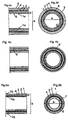
- Fig. 1a shows in longitudinal section a non-inventive structural element 10.
- Die Fig. 1b shows the corresponding cross section of the structural element 10.
- a flexible support tube 1 is provided as a structuring element in the interior.
- a tubular fabric 2 is applied, which is located on the outer circumferential surface of the tube 1, on which then a plastic 3 is applied, which forms a matrix.
- the layer 4 denotes a further layer with or without tubular fabric and a plastic.
- the mean outer diameter a of the flexible tube 1 is about 30 mm, the average wall thickness d is 1.5 mm (the average value is the arithmetic mean 25).
- Fig. 2a and 2b are the analog views of the Fig. 1a and 1b shown, here the order of the individual layers has been changed.
- a tubular fabric 2 is now arranged, which was then provided with a curable plastic compound 3.
- the layer 4 identifies another such layer.
- the in the Fig. 1a to 2b Non-inventive embodiments shown comprise a flexible hose 1 made of PVC, a tubular fabric 2 made of glass fiber fabric and a plastic comprising cured polyester resin.
- Fig. 3a and 3b show a further non-inventive embodiment based on the embodiment of Fig. 1a and 1b ,
- a flexible carrier tube 1 as a structuring element in the interior.
- a tubular fabric 2 is applied, which lies on the outer circumferential surface of the tube 1, on which then a plastic 3 is applied, which forms a matrix.
- the layer 4 denotes a further layer with or without tubular fabric and a plastic.
- a further tubular jacket 5 in the form of a shrink tube is arranged on the tubular fabric 2.
- Fig. 4a and 4b shows a variant of the embodiment of Fig. 3a and 3b However, in this case with a flow aid 6 between flexible hose 1 and tubular fabric 2 for better infusion of liquid plastic.
- Fig. 4c and 4d also show a variant of the embodiment of Fig. 3a and 3b However, this time with a flow aid 6 between tubular fabric 2 and the other hose jacket. 5
- Fig. 5a and 5b leans on the embodiment of the Fig. 2a and 2b at.
- hose jacket 5 which is, however, designed inflatable in this embodiment.
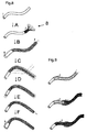
- Fig. 6 the individual steps of a non-inventive method for the production of a structural element 10 are shown, in which the flexible tube 1 is arranged in the interior of the structural element 10.
- the tubular fabric 2 is slipped over the flexible hose 1 and to the outer circumferential surface in step A. 1a is created, as can be seen in step B.
- a second tubular fabric 2 ' is applied and pulled accordingly tight.
- Step D shows that the flexible hose 1 together with tubular fabric 2, 2 'is brought into the desired shape.
- holding elements can be used.
- step E a liquid plastic is then applied as plastic resin 3 to the tubular fabric 2, 2 ', so that a fiber-reinforced plastic with two tubular fabrics 2, 2' is formed.
- the plastic resin 3 is then cured, so that the finished structural element 10 is present.
- step F the tube 1 is removed from the cured structural element again.
- the Fig. 7 shows a method according to the invention.
- the tubular fabric 2 is introduced into the interior of the tube 1.
- the tubular fabric 2 can, on the one hand, be woven from individual rovings 8 directly onto a further tubular jacket 5 which assumes the function of an insertion aid 5 (indicated by the individual rovings 8 of the tubular fabric in step A).
- the tubular fabric 2 may be prefabricated and slid onto the insertion aid 5 (not shown).
- the insertion aid 5 (inflatable tube 5) and tubular fabric 2 are brought into position by insertion into the flexible tube 1 (step B).
- step C the flexible tube 1 together with tubular fabric 2 is brought into the desired shape.
- Step D now shows schematically the application of the liquid plastic 3.
- the plastic resin in the interior (in the arrow direction) of the tube 1 are introduced.
- a lower pressure for example vacuum
- the inflatable tube 5 can be removed after the introduction of the plastic resin by means of positive or negative pressure again.
- the outer jacket (flexible tube 1) is cut open and removed in optional step E. What remains is the fiber-reinforced plastic as a structural element 10 with a particularly smooth outer contour, since this has taken over the inner contour of the tube 1. Step E can also be omitted.
- a tubular fabric 2 of rovings 8 is woven onto the flexible hose 1 in step A and applied to the outer circumferential surface 1a (step A).
- step B an additional tubular jacket 5 in the form of a shrink tube is applied to the tubular fabric 2.
- step C the shaping of flexible hose 1 with tubular fabric 2 and shrink tube 5 in the desired final shape.
- step D the shrink tube 5 is shrunk by the action of temperature, so that it rests tightly on the tubular fabric 2.
- step E a liquid plastic is applied as a plastic resin 3 on the tubular fabric 2 by being inserted between shrink tube 5 and flexible tube 1, so that the tubular fabric wets with the liquid plastic resin 3.
- the plastic resin 3 is then cured,
- step F the shrink tube 5 can be removed. Steps C and D can also be done in reverse order.
- Fig. 9 shows a variant not according to the invention for the example of Fig. 8 where first on the flexible tube 1, a flow aid 6 is applied, so that the liquid plastic 3 can better penetrate between shrink tube 5 and flexible hose 1. Subsequently, the tubular fabric 2 (here directly as a hose) is applied in two layers with a flow aid 6 as an intermediate layer.
- tubular fabric 2 either as a prefabricated biaxial tube ( Fig. 10a ) or can be woven directly on the flexible hose 1 of rovings 8.
- tubular fabric 2 which is cylindrical-shaped and has an inner diameter, so that it is a flexible hose 1, as in the Fig. 11b shown dashed, would be pushed.
- the tubular fabric 2 may also be formed as in the right part of the Figure 11b recognizable that it is extensible in the longitudinal direction and thus reduces its inner diameter and thus in the interior of the flexible tube 1 is inserted.
- FIG. 12a to 12e different embodiments are shown how the individual structural elements 10 could be arranged to each other to form an assembly 11. These could on the one hand be arranged aesthetically, on the other hand, be used for more complex structures such as structural modules, support elements, structures and free formable and shapable surface structures.
- Fig. 13a to 13c show three views of an arrangement 11 of structural elements 10.
- Die Fig. 13a shows a side view, the Fig. 13b a plan view and the Fig. 13c an oblique view.
- Fig. 13a a human drawn in, so that it is clear that the arrangement 11 forms a kind of roof construction.
Landscapes
- Engineering & Computer Science (AREA)
- Mechanical Engineering (AREA)
- Textile Engineering (AREA)
- Chemical & Material Sciences (AREA)
- Composite Materials (AREA)
- Architecture (AREA)
- Wood Science & Technology (AREA)
- Life Sciences & Earth Sciences (AREA)
- Civil Engineering (AREA)
- Structural Engineering (AREA)
- Moulding By Coating Moulds (AREA)
- Rigid Pipes And Flexible Pipes (AREA)
- Laminated Bodies (AREA)
- Reinforced Plastic Materials (AREA)
Description
- Die Erfindung betrifft ein Verfahren zur Herstellung eines Strukturelements, umfassend einen faserverstärkten Kunststoff.
- Aus der
US 6,082,075 ist die Herstellung von Strukturelementen, umfassend einen faserverstärkten Kunststoff, bereits bekannt. Dabei wird ein Skelett aus Rohren und Spanten mit mehreren Halteelementen in die gewünschte Form gebracht und anschließend mit einem Gewebe, das um dieses Skelett gewickelt wird, versehen. Schließlich wird ein Kunststoff aufgebracht, der zur Aushärtung gebracht wird und dem Strukturelement die endgültige Form gibt. Vereinfacht ausgedrückt schlägt dieUS 6,082,075 die Herstellung von Kastenholmen vor, wobei ein Skelett - nachdem es in die gewünschte Form gebracht wurde - mit Gewebe umwickelt wird und hernach auf dieses Gewebe aushärtbarer Kunststoff aufgebracht wird. - Das in der
US 6,082,075 beschriebene Verfahren weist den Nachteil auf, dass die Herstellung des formgebenden Skelettes aus Rohren, Halteelementen und Spanten sehr aufwändig ist und dass aufgrund der Komplexität des vorgeschlagenen Skelettes die Formbarkeit der Strukturelemente engen Grenzen unterliegt. So sind beispielsweise enge Biegeradien oder komplexere Topologien wie z.B. Schlingen, Schlaufen oder Knoten nicht oder nur mit erheblichem Aufwand machbar. Weiters ist das in derUS 6,082,075 vorgeschlagene Aufbringen des Gewebes durch Umwickeln der finalen Form sehr aufwändig und zusätzlich weist die so erzielbare Oberfläche aufgrund der Wickelstruktur des Gewebes optische Beeinträchtigungen auf. - Die
US 6,082,075 schlägt ein weiteres Verfahren vor, in welchem anstelle des formgebenden Skelettes aus Rohren, Halteelementen und Spanten eine aufblasbare Blase als Positiv-Form für die Aufbringung des faserverstärkten Kunststoffes verwendet wird, wobei diese Blase so ausgebildet sein muss, dass sie durch das Aufblasen die gewünschte Form einnimmt, auf welche hernach das Gewebe durch Umwickeln aufgebracht wird. - Dieses Verfahren weist die Nachteile auf, dass einerseits die Herstellung einer solchen aufblasbaren Positv-Form, welche durch den Aufblasdruck die gewünschte Form einnehmen soll, sehr aufwändig ist und andererseits auch hier enge Biegeradien oder komplexere Topologien wie z.B. Schlingen, Schlaufen oder Knoten nicht oder nur mit erheblichem Aufwand machbar sind.
- Weiters eignen sich die in der
US 6,082,075 vorgeschlagen Strukturelemente nicht oder nur unter unverhältnismäßig hohem Herstellungs- und Kostenaufwand zum Verbund zu komplexeren Konstruktionsmodulen, Trägerelementen, Tragwerken und frei form- und gestaltbaren Flächentragwerken. - Aus der
WO 95/30532 A1 - Aus der
JP 57 022016 A - Aus der
EP 1 264 717 A2 ist ein Verfahren zur Herstellung einer Klimaanlagen-Leitung bekannt. Eine kältemitteldichte Elastomerschlauch-Seele wird mit einer flexiblen Faserhülle versehen, die eine Kunststoffimprägnierung aufweist. Die Elastomerschlauch-Seele wird zusammen mit der Faserhülle und der Kunststoffimprägnierung in einer Form fixiert und unter einen Innendruck gesetzt, so dass das gesamte Gebilde gegen eine Formhohlraumwand angedrückt wird. Durch einen Heizvorgang erfolgt ein Aushärten der Kunststoffimprägnierung. - Aus der
JP 58 119822 A - Aus der
CH 459 549 A - Aus der
US 4 756 386 A ist ein Verfahren zur Herstellung eines faserverstärkten, gebogenen Rohres bekannt. Zur Herstellung wird ein Kern verwendet, der ein elastisches Rohr aufweist, das mittels einer Feder verstärkt ist. Auf den Kern wird eine Faserschicht aufgetragen. Anschließend wird der Kern zusammen mit der Faserschicht gebogen und in eine aus zwei Teilen bestehende Außenform gegeben. Über einen Einlass wird der Außenform flüssiges Harz zugeführt. Nach dem Aushärten des Harzes wird die Außenform entfernt und der Kern aus dem faserverstärkten Rohr gezogen. - Aus der
DE 103 04 044 A1 ist ein Verfahren zur Herstellung von Rohren aus Faserverbundmaterial bekannt. Zur Herstellung eines Rohres wird ein Montagekern zunächst mit einer luftdichten Schicht und mit mindestens zwei Leitungen versehen. Die Leitungen ermöglichen ein Fließen des einzubringenden Matrixmaterials mit einem vergleichsweise geringen Fließwiderstand. Auf den Montagekern wird eine Verteilerschicht und eine Verstärkungsfaserschicht aufgebracht, wobei der derart bestückte Montagekern in eine Außenform eingelegt wird. Anschließend wird Matrixmaterial injiziert, das die Verstärkungsfaserschicht tränkt. - Aus der
EP 1 170 117 A1 ist die Herstellung von faserverstärkten Rohrkörpern bekannt. Das Matrixmaterial wird durch Anlegen eines Vakuums in eine Schicht aus Verstärkungsfasern eingebracht. Hierzu sind die Verstärkungsfasern von einem luftdichten Material umgeben, das entweder von einem Vakuumschlauch oder einer Form gebildet wird. - Der Erfindung liegt die Aufgabe zugrunde, ein einfaches Verfahren zur Herstellung eines frei formbaren und nach dem Aushärten stabilen Strukturelements zu schaffen.
- Diese Aufgabe wird durch ein Verfahren gemäß Anspruch 1 gelöst.
- Die Erfindung beruht auf der Erkenntnis, dass ein vorzugsweise dehnbares Schlauchgewebe rascher mit einem flexiblen formgebenden Element in Berührung gebracht werden kann und die anschließende Tränkung mit flüssigem Kunststoff einfacher erfolgen kann, als wenn ein bandförmiges Gewebe um eine Positiv-Form gewickelt werden muss. Das flexible form-gebende Element ist als flexibler Schlauch ausgebildet. Dabei ist insbesondere auch von Vorteil, dass der (als formgebendes Element dienende) flexible Schlauch bereits bevor er in die gewünschte finale Form gebracht wird mit dem (zur Faserverstärkung des Kunststoffs dienenden) Schlauchgewebe versehen werden kann. Bei der Herstellung von komplexeren Strukturen und Anordnungen, welche aus einem Verbund von mehreren erfindungsgemäßen Strukturelementen bestehen, ist es dadurch möglich, die einzelnen Strukturelemente bereits vor dem Zusammenfügen zum Verbund und bereits vor der finalen Formgebung mit dem Gewebe zu versehen. Die Herstellung von komplexen Elementen (wie beispielsweise Konstruktionsmodule, Trägerelemente, Tragwerke und frei form- und gestaltbaren Flächentragwerke) kann so - verglichen mit Verfahren, bei denen das Gewebe erst um die finale Form gewickelt wird - wesentlich vereinfacht werden, wodurch deutliche Produktions- und Kostenvorteile erzielbar sind.
- Das Schlauchgewebe wird vor dem Versehen mit flüssigem Kunststoff bzw. vor dem Aushärten des Kunststoffs mit einem zusätzlichen Schlauchmantel versehen. Diese Maßnahme führt dazu, dass die Oberfläche des ausgehärteten Kunststoffs ebenmäßiger ausgebildet ist, was beispielsweise optisch ansprechendere Ergebnissen liefert, weil der zusätzliche Schlauchmantel die Oberflächenstruktur vorgibt und ebenfalls wird eines bessere Durchtränkung der Faserkomponente mit dem flüssigen Kunststoff bewirkt.
- Von der Handhabungsseite hat es sich als vorteilhaft erwiesen, wenn der flüssige Kunststoff zwischen flexiblen Schlauch und zusätzlichem Schlauchmantel infundiert wird. Dabei wird zwischen zusätzlichem Schlauchmantel und Schlauchgewebe oder zwischen flexiblen Schlauch und Schlauchgewebe eine Fließhilfe eingebracht. Die Fließhilfe kann beispielsweise auch aufgeflochten werden. Die Fließhilfe bewirkt einerseits eine bessere Infundierbarkeit des Kunststoffes und andererseits auch einen Sandwicheffekt zur Stabilisierung des fertigen Strukturelements. Dadurch wird eine höhere statische Belastbarkeit erzielt. Die Fließhilfe kann z.B. eine maschenartiges Geflecht, ein vliesartiges Gewebe aus Kunststofffasern wie PE, Polyamid, PP etc sein.
- Das Verfahren erweist sich als vorteilhaft, da das Schlauchgewebe in das Innere des flexiblen Schlauchs eingebracht wird. Gemäß der
US 6,082,075 hergestellte Strukturelemente müssen das formgebende Element praktisch immer im Inneren beherbergen, d.h. das Gewebe muss außen auf das form-gebende Element aufgewickelt werden. Demgegenüber ist es mit einem Schlauchgewebe möglich, dieses in das Innere des flexiblen Schlauchs, d.h. auf dessen Innenmantelfläche einzubringen und anschließend durch Aufbringen von flüssigem Kunststoff, der ausgehärtet wird, das endgültige Strukturelement herzustellen. Dabei ist vorgesehen, dass der flüssige Kunststoff durch das Anlegen eines erhöhten Drucks in das Innere des flexiblen Schlauchs eingebracht wird. Weiters kann erfindungsgemäß vorgesehen sein, nach dem Tränken des Schlauchgewebes mit flüssigem Kunststoff überschüssigen Kunststoff aus dem Innenvolumen des Schlauches mittels Über- oder Unterdruck oder mechanisch zu entfernen, was sowohl Gewichts- als auch Kostenvorteile bringt. - Der flexible Schlauch ist ausgewählt aus der Gruppe Gummi, PVC, PE, PA, PU, der Silikone oder PTFE.
- Bevorzugt kann vorgesehen sein, dass der Schlauch nach dem Aushärten des Kunststoffs zumindest teilweise wieder entfernt wird. Zurück bleibt in diesem Fall nur mehr noch der faserverstärkte Kunststoff als Strukturelement. Dies ist besonders einfach zu bewerkstelligen da das Schlauchgewebe in das Innere des flexiblen Schlauchs eingebracht wurdeund der flexible Schlauch beispielsweise aufgeschnitten und entfernt werden kann.
- Die Flexibilität des Schlauches sollte so gestaltet sein, dass dieser ohne große Kraftaufwendungen in die gewünschte Form gebracht werden kann. Zu diesem Zweck ist es vorteilhaft (auch abhängig von der jeweiligen Materialwahl), wenn der Schlauch einen Durchmesser von 5 mm bis 100 mm und eine Wandstärke von 0,5 mm bis 15 mm aufweist. Die Flexibilität des Schlauchs hängt unter anderem vom Elastizitätsmodul des Materials ab. Ausgehend von der mittleren Wandstärke des Schlauchs und der Materialauswahl ist es günstig, wenn der Schlauch so flexibel ist, dass er mit einer Kraft von unter 500 N, vorzugsweise unter 100 N, in die gewünschte Form gebracht werden kann. Der Elastizitätsmodul wird standardmäßig in N/mm2 und bei einer Temperatur von 20°C angegeben. Dementsprechend können natürlich auch biegeweiche Rohre eingesetzt werden. Hieraus kann der Fachmann leicht ermitteln, welche Materialien und Querschnittsflächen des Schlauchs auszuwählen sind. Der flexible Schlauch weist im einfachsten Fall einen kreisringförmigen Querschnitt auf, ist also beispielsweise als Kreiszylindermantel ausgebildet. Selbstverständlich kann der Schlauch aber auch vom Kreisring abweichende Querschnittsformen aufweisen. Der Schlauch kann sowohl eine Innenkontur als auch Außenkontur (im Querschnitt) aufweisen, die polygonartig, rechteckig, quadratisch, elliptisch ist oder eine sonstige geschlossene Kurvenform aufweisen.
- Ein weiterer Vorteil der Erfindung liegt darin, dass der als formgebendes Element dienende flexible Schlauch aufgrund seiner Eigensteifigkeit in die finale Form gebracht werden kann, indem man Kräfte und/oder Drehmomente lediglich an einzelnen Punkten einbringt. Beispielsweise sind auf diese Weise Formen wie Biegungen, S-Kurven, sogenannte Spline-Kurven sowie Schlingen und Schlaufen bis hin zu Knoten ohne aufwändigen Formenbau realisierbar. Die Formgebung kann z.B. über eine Modelliermaschine CNC gesteuert ablaufen.
- Erfindungsgemäß ist auch vorgesehen, dass ein Verbund aus einzelnen erfindungsgemäßen Strukturelementen vor dem Aushärten des Kunststoffes durch das Einbringen von Kräften und/oder Drehmomenten lediglich an einzelnen Punkten in die finale Form gebracht wird, wodurch auch beispielsweise frei geformte Flächentragwerke ohne aufwändigen Formenbau realisierbar sind.
- In einer Ausführungsvariante kann vorgesehen sein, dass das Schlauchgewebe mehrere Lagen aufweist, und/oder dass zusätzliche Schichten vorgesehen sind, um dem Strukturelement eine höhere Steifigkeit zu verleihen.
- Im einfachsten Fall kann vorgesehen sein, dass der flüssige Kunststoff durch Polymerisation ausgehärtet wird. Hierbei haben sich insbesondere Kunststoffe, ausgewählt aus der Gruppe der Epoxidharze, Polyesterharze, Vinylesterharze oder Mischungen daraus bewährt. Die Polymerisation kann dabei wie an sich bekannt beispielsweise durch UV-Strahlung, thermische Behandlung oder Lufttrocknung etc. erfolgen.
- Weiters kann vorgesehen sein, dass das Schlauchgewebe ausgewählt ist aus der Gruppe von gewebten und geflochtenen Glasfasern, Kohlenstofffasern, Aramidfasern, Basaltfasern, Hanf, Flachs, Baumwolle oder Mischungen daraus. Glasfasern haben sich dabei als bevorzugtes Ausführungsbeispiel erwiesen, da sie einerseits kostengünstig sind bei gleichzeitig sehr hoher Belastbarkeit. Zusätzlich sind sie aufgrund ihrer Farblosigkeit in vielen Bereichen, die lichtdurchlässig sein sollen, bevorzugt einsetzbar.
- Besonders bevorzugt ist vorgesehen, dass das Schlauchgewebe zylindermantelförmig ausgebildet ist. Weiters ist bevorzugt vorgesehen, dass das Schlauchgewebe derart gewebt ist, dass es radial und in Längsrichtung dehnbar ist, was für das Aufbringen auf oder das Einbringen in den als formgebendes Element dienenden flexiblen Schlauch von Vorteil ist. Hier kann sich ein beispielsweise biaxial gewebtes bzw. geflochtenes Gewebe als günstig erweisen.
- In der Ausführungsvariante mit außen liegendem Schlauchgewebe ist besonders bevorzugt vorgesehen, dass das Schlauchgewebe derart gewebt bzw. geflochten ist, dass sich bei Zug in Längsrichtung sein Radius verkleinert. Dadurch kann bei Auswahl eines Schlauchgewebes, welches einen Innendurchmesser aufweist, der einige Prozent größer ist, als der Außendurchmesser des flexiblen Schlauches, das Schlauchgewebe leicht über den flexiblen Schlauch gestülpt werden und hernach durch einfaches Ziehen an beiden Enden straff auf den als formgebendes Element dienenden Schlauch gespannt werden, was sowohl für die Einfachheit des Verfahrens, als auch für die erzielbare Qualität der Oberfläche von Vorteil ist.
- In der Ausführungsvariante mit innen liegendem Schlauchgewebe ist besonders bevorzugt vorgesehen, dass das Schlauchgewebe derart gewebt ist, dass es radial dehnbar ist, sodass für leichtes Einführen in den formgebenden Schlauch ein Schlauchgewebe gewählt werden kann, dessen Außendurchmesser einige Prozent kleiner ist, als der Innendurchmesser des Schlauches, und das Schlauchgewebe hernach durch radiales Dehnen an die Innenwand des formgebenden Schlauches geschmiegt werden kann - beispielsweise mittels geeigneten Bürsten oder durch Einbringen und Aufblasen eines weiteren aufblasbaren Innenschlauches.
- Es kann vorgesehen sein, dass der zusätzliche Schlauchmantel nach dem Aushärten des Kunststoffs entfernt wird, speziell, wenn die Oberfläche des erhaltenen Strukturelements aus dem gehärteten Kunststoff gebildet sein soll. Theoretisch kann der zusätzliche Schlauchmantel aber auch am Strukturelement verbleiben.
- Das Schlauchgewebe ist an der inneren Mantelfläche des flexiblen Schlauchs angeordnet.
- Generell ist für das hergestellte Strukturelement zu sagen, dass die oben erwähnten Materialien und Dimensionen für das Verfahren auch für das Strukturelement zutreffen. Dies bedeutet, dass der flexible Schlauch ausgewählt ist aus der Gruppe Gummi, PVC, PE, PA, PU der Silikone und PTFE. Dessen Dimension kann zwischen 5 mm und 100 mm bei einer mittleren Wandstärke von 0,5 mm bis 15 mm betragen. Das Schlauchgewebe kann mehrlagig ausgebildet sein und der ausgehärtete Kunststoff kann ein Polymerisat aus der Gruppe der Epoxidharze, Polyesterharze, Vinylesterharze oder Mischungen daraus sein. Das Strukturelement ist im Inneren hohl ausgebildet.
- Das Schlauchgewebe ist bevorzugt aus der Gruppe von gewebten Glasfasern, Kohlenstofffasern, Aramidfasern, Basaltfasern, Hanf, Flachs, Baumwolle oder Mischungen daraus hergestellt und idealerweise zylindermantelförmig ausgebildet. Besonders bevorzugt ist das Schlauchgewebe radial und in Längsrichtung dehnbar ausgebildet, indem es beispielsweise biaxial gewebt ist. Sowohl zum Verfahren als auch zum Strukturelement gilt zu sagen, dass besonders bevorzugt vorgesehen ist, dass der flexible Schlauch unmittelbar mit dem Schlauchgewebe in Kontakt gebracht wird, d.h. dass das Schlauchgewebe unmittelbar an den flexiblen formgebenden Schlauch angrenzt. Auch kann der flexible Schlauch wenigstens abschnittsweise perforiert sein. Dadurch kann die Masse des Strukturelements erniedrigt werden, ohne dass es zu einer nennenswerten Stabilitätsverminderung kommt. Es gibt diverse Verwendungsmöglichkeiten der zuvor beschriebenen Strukturelemente. Dies kann einerseits eine einfache Anordnung mehrerer solcher Strukturelemente umfassen. Darüber hinaus sind komplexere Anordnungen wie beispielsweise Konstruktionsmodule, Trägerelemente, Tragwerke und frei form- und gestaltbare Flächentragwerke, Dachkonstruktionen oder andere Gebilde, die durch solche Strukturelemente herstellbar sind, denkbar.
- Bei Anordnungen ist vorgesehen, dass zumindest zwei Strukturelemente nach dem zuvor beschriebenen Verfahren hergestellt werden, die miteinander verbunden werden. Die wenigstens zwei Strukturelemente können dabei vor dem Aushärten des Kunststoffs miteinander verbunden werden. Dabei ist es also entweder möglich, den flexiblen Schlauch, der mit dem Schlauchgewebe versehen worden ist, mit einem zweiten flexiblen Schlauch, der mit einem Schlauchgewebe versehen worden ist, vor oder nach dem Aufbringen des Kunststoffs miteinander zu verbinden und den Kunststoff anschließend auszuhärten. Das Verbinden kann wie an sich bekannt mit Halteelementen, Klebeverbindungen usw. erfolgen.
- Typische Einsatzgebiete der Strukturelemente der vorgenannten Art sind beispielsweise in Dachkonstruktionen, Deckenelementen, Fassadenelementen, Möbelteilen, Beleuchtungskörpern, in Rauminstallationen oder dergleichen. Die zuvor genannten Strukturelemente können auch mit anderen Materialien wie z.B. Textilien, plattenförmigen Materialien etc. kombiniert bzw. eingearbeitet werden.
- Weitere Details und Vorteile der Erfindung sollen anhand der folgenden Figuren und Figurenbeschreibungen erläutert werden. Es zeigen:
- Fig. 1a, 1b
- ein erstes Ausführungsbeispiel für ein nicht erfindungsgemäßes Strukturelement in Längs- und Querschnitt,
- Fig. 2a und 2b
- ein zweites Ausführungsbeispiel eines nicht erfindungsgemäßen Strukturelements in Längs- und Querschnitt,
- Fig. 3a und 3b
- ein drittes Ausführungsbeispiel eines nicht erfindungsgemäßen Strukturelements in Längs- und Querschnitt,
- Fig. 4a bis 4d
- ein viertes und fünftes Ausführungsbeispiel von Strukturelementen in Längs- und Querschnitt,
- Fig. 5a und 5b
- ein sechstes Ausführungsbeispiel eines Strukturelements in Längs- und Querschnitt,
- Fig. 6
- einzelne Verfahrensschritte für ein nicht erfindungsgemäßes Verfahren,
- Fig. 7
- Verfahrensschritte für ein erfindungsgemäßes Verfahren,
- Fig. 8 und 9
- Verfahrensschritte für ein nicht erfindungsgemäßes Verfahren,
- Fig. 10a und 10b
- Detailansichten der Verfahrensschritte "A" der
Fig. 6 und 7 , - Fig. 11 a und 11b
- ein Schlauchgewebe in unterschiedlichen Positionen zur Verwendung für ein erfindungsgemäßes Verfahren,
- Fig. 12a bis 12e
- mögliche Anordnungen der Strukturelemente und
- Fig. 13a bis 13c
- drei Ansichten einer Anordnung von Strukturelementen.
- Die
Fig. 1a zeigt im Längsschnitt ein nicht erfindungsgemäßes Strukturelement 10. DieFig. 1b zeigt den entsprechenden Querschnitt des Strukturelements 10. Dabei ist ein flexibler Trägerschlauch 1 als strukturgebendes Element im Inneren vorgesehen. Um den flexiblen Schlauch 1 ist nunmehr ein Schlauchgewebe 2 aufgebracht, das an der Außenmantelfläche des Schlauchs 1 liegt, auf das anschließend ein Kunststoff 3 aufgebracht wird, der eine Matrix bildet. Die Schicht 4 kennzeichnet eine weitere Schicht mit oder ohne Schlauchgewebe und einem Kunststoff. Der mittlere Außendurchmesser a des flexiblen Schlauches 1 beträgt etwa 30 mm, die mittlere Wandstärke d 1,5 mm (als mittlerer Wert ist der arithmetische Mittelwert 25 gedacht). - In den
Fig. 2a und 2b sind die analogen Ansichten derFig. 1a und 1b gezeigt, wobei hier die Reihenfolge der einzelnen Schichten verändert wurde. An der Innenmantelfläche 1a des flexiblen Trägerschlauchs 1 ist nunmehr ein Schlauchgewebe 2 angeordnet, das anschließend mit einer härtbaren Kunststoffmasse 3 versehen wurde. Die Schicht 4 kennzeichnet eine weitere solche Schicht. Die in denFig. 1a bis 2b gezeigten nicht erfindungsgemäßen Ausführungsbeispiele umfassen einen flexiblen Schlauch 1 aus PVC, ein Schlauchgewebe 2 aus Glasfasergewebe und einen Kunststoff, der gehärtetes Polyesterharz umfasst. - Die
Fig. 3a und 3b zeigen eine weitere nicht erfindungsgemäße Ausführungsvariante angelehnt an das Ausführungsbeispiel derFig. 1a und 1b . Erneut erkennbar ist ein flexibler Trägerschlauch 1 als strukturgebendes Element im Inneren. Um den flexiblen Schlauch 1 ist ein Schlauchgewebe 2 aufgebracht, das an der Außenmantelfläche des Schlauchs 1 liegt, auf das anschließend ein Kunststoff 3 aufgebracht wird, der eine Matrix bildet. Die Schicht 4 kennzeichnet eine weitere Schicht mit oder ohne Schlauchgewebe und einem Kunststoff. Zusätzlich ist auf dem Schlauchgewebe 2 ein weiterer Schlauchmantel 5 in der Form eines Schrumpfschlauches angeordnet. - Das Ausführungsbeispiel der
Fig. 4a und 4b zeigt eine Variante des Ausführungsbeispiels derFig. 3a und 3b allerdings in diesem Fall mit einer Fließhilfe 6 zwischen flexiblen Schlauch 1 und Schlauchgewebe 2 zum besseren infundieren von flüssigem Kunststoff.Fig. 4c und 4d zeigen ebenfalls eine Variante des Ausführungsbeispiels derFig. 3a und 3b , diesmal allerdings mit einer Fließhilfe 6 zwischen Schlauchgewebe 2 und dem weiteren Schlauchmantel 5. - Das Ausführungsbeispiel der
Fig. 5a und 5b lehnt sich an das Ausführungsbeispiel derFig. 2a und 2b an. Zusätzlich ist im Inneren ein weiterer Schlauchmantel 5, der in diesem Ausführungsbeispiel allerdings aufblasbar gestaltet ist. - In der
Fig. 6 sind die einzelnen Schritte eines nicht erfindungsgemäßen Verfahrens für die Herstellung eines Strukturelements 10 gezeigt, bei dem der flexible Schlauch 1 im Inneren des Strukturelements 10 angeordnet ist. Ausgehend vom flexiblen Schlauch 1 wird in Schritt A das Schlauchgewebe 2 über den flexiblen Schlauch 1 gestülpt und an die Außenmantelfläche 1a angelegt, wie in Schritt B erkennbar ist. In Schritt C wird ein zweites Schlauchgewebe 2' aufgebracht und entsprechend straff gezogen. Schritt D zeigt, dass der flexible Schlauch 1 samt Schlauchgewebe 2, 2' in die gewünschte Form gebracht wird. Hierfür können nicht gezeigte Halteelemente verwendet werden. In Schritt E wird anschließend ein flüssiger Kunststoff als Kunststoffharz 3 auf das Schlauchgewebe 2, 2' aufgetragen, sodass sich ein faserverstärkter Kunststoff mit zwei Schlauchgeweben 2, 2' ausbildet. Das Kunststoffharz 3 wird anschließend ausgehärtet, sodass das fertige Strukturelement 10 vorhanden ist. In einem optionalen Schritt F wird der Schlauch 1 aus dem ausgehärteten Strukturelement wieder entfernt. - Die
Fig. 7 zeigt ein erfindungsgemäßes Verfahren. Dabei wird das Schlauchgewebe 2 in das Innere des Schlauchs 1 eingeführt. Das Schlauchgewebe 2 kann einerseits aus einzelnen Rovings 8 direkt auf einen weiteren Schlauchmantel 5, der die Funktion einer Einführhilfe 5 übernimmt, aufgeflochten werden (angedeutet durch die einzelnen Rovings 8 des Schlauchgewebes in Schritt A). Andererseits kann das Schlauchgewebe 2 vorgefertigt sein und auf die Einführhilfe 5 aufgeschoben werden (nicht gezeigt). Die Einführhilfe 5 (aufblasbarer Schlauch 5) und Schlauchgewebe 2 werden in Position gebracht durch Einführen in den flexiblen Schlauch 1 (Schritt B). In Schritt C wird der flexible Schlauch 1 samt Schlauchgewebe 2 in die gewünschte Form gebracht. Schritt D zeigt nun schematisch das Aufbringen des flüssigen Kunststoffs 3. Hierzu kann beispielsweise durch Druck das Kunststoffharz in das Innere (in Pfeilrichtung) des Schlauches 1 eingebracht werden. Hierbei ist von Vorteil, den Druck lediglich ins Volumen zwischen Schlauch 1 und aufblasbarem Schlauch 5 einzubringen, sodass das Kunststoffharz lediglich das zwischen Schlauch 1 und aufblasbarem Schlauch 5 liegende Schlauchgewebe 2 tränkt und nicht das gesamte Innenvolumen von Schlauch 1 ausfüllt, was kosten- und Gewichtsvorteile bringt. Auch wäre es möglich, an der anderen Seite des Schlauches 1 einen niedrigeren Druck (beispielsweise Vakuum) - vorteilhafterweise wiederum lediglich am Volumen zwischen Schlauch 1 und aufblasbarem Schlauch 5 - anzulegen, um das Kunststoffharz in das Innere des Schlauches 1 zu befördern. Der aufblasbare Schlauch 5 kann nach dem Einbringen des Kunststoffharzes mittels Über- oder Unterdruck wieder entfernt werden. Nach einem Aushärteschritt wird im optionalen Schritt E der Außenmantel (flexibler Schlauch 1) aufgeschnitten und entfernt. Zurück bleibt der faserverstärkte Kunststoff als Strukturelement 10 mit besonders glatter Außenkontur, da dieser die Innenkontur des Schlauchs 1 übernommen hat. Schritt E kann aber auch entfallen. - In der
Fig. 8 sind einzelne Verfahrensschritte für die Herstellung eines weiteren nicht erfindungsgemäßen Ausführungsbeispiels eines Strukturelements 10 gezeigt, bei dem der flexible Schlauch 1 im Inneren des Strukturelements 10 angeordnet ist. Ausgehend vom flexiblen Schlauch 1 wird in Schritt A ein Schlauchgewebe 2 aus Rovings 8 auf den flexiblen Schlauch 1 gewebt und an die Außenmantelfläche 1a angelegt (Schritt A). In Schritt B wird ein zusätzlicher Schlauchmantel 5 in Form eines Schrumpfschlauchs auf das Schlauchgewebe 2 aufgebracht. Anschließend erfolgt die Formgebung von flexiblen Schlauch 1 mit Schlauchgewebe 2 und Schrumpfschlauch 5 in die gewünschte Endform (Schritt C). In Schritt D wird der Schrumpfschlauch 5 mittels Temperatureinwirkung geschrumpft, sodass er eng am Schlauchgewebe 2 anliegt. In Schritt E wird ein flüssiger Kunststoff als Kunststoffharz 3 auf das Schlauchgewebe 2 aufgetragen, indem er zwischen Schrumpfschlauch 5 und flexiblen Schlauch 1 eingebracht wird, so dass sich das Schlauchgewebe mit dem flüssigen Kunststoffharz 3 benetzt. Das Kunststoffharz 3 wird anschließend ausgehärtet, In einem optionalen Schritt F kann der Schrumpfschlauch 5 entfernt werden. Die Schritte C und D können auch in umgekehrter Reihenfolge statt finden. -
Fig. 9 zeigt eine nicht erfindungsgemäße Variante für das Beispiel derFig. 8 wo zunächst auf den flexiblen Schlauch 1 eine Fließhilfe 6 aufgebracht wird, damit der flüssige Kunststoff 3 besser zwischen Schrumpfschlauch 5 und flexiblen Schlauch 1 eindringen kann. Anschließend wird das Schlauchgewebe 2 (hier direkt als Schlauch) in zwei Lagen mit einer Fließhilfe 6 als Zwischenlage aufgebracht. -
Fig. 10a und 10b zeigen, dass das Schlauchgewebe 2 entweder als vorgefertigter biaxialer Schlauch (Fig. 10a ) oder direkt am flexiblen Schlauch 1 aus Rovings 8 gewebt werden kann. - In der
Fig. 11a ist ein Schlauchgewebe 2 erkennbar, das zylindermantelförmig ausgebildet ist und einen Innendurchmesser aufweist, sodass es um einen flexiblen Schlauch 1, wie in derFig. 11b strichliert dargestellt, schiebbar wäre. Allerdings kann das Schlauchgewebe 2 auch so ausgebildet sein, wie im rechten Teil derAbbildung 11b erkennbar, dass er in Längsrichtung dehnbar ist und somit seinen Innendurchmesser verkleinert und damit in das Innere des flexiblen Schlauchs 1 einführbar ist. - In den
Fig. 12a bis 12e sind unterschiedliche Ausgestaltungen gezeigt, wie die einzelnen Strukturelemente 10 zueinander angeordnet sein könnten, um eine Anordnung 11 zu bilden. Diese könnten einerseits ästhetisch angeordnet werden, andererseits für komplexere Strukturen wie beispielsweise Konstruktionsmodule, Trägerelemente, Tragwerke und frei form- und gestaltbaren Flächentragwerke eingesetzt werden. - Die
Fig. 13a bis 13c zeigen drei Ansichten einer Anordnung 11 von Strukturelementen 10. DieFig. 13a zeigt dabei eine Seitenansicht, dieFig. 13b eine Draufsicht und dieFig. 13c eine Schrägansicht. Zur Verdeutlichung ist in derFig. 13a ein Mensch eingezeichnet, sodass klar ist, dass die Anordnung 11 eine Art Dachkonstruktion bildet. - Selbstverständlich ist denkbar und in weiteren Ausführungsbeispielen vorgesehen, die Strukturelemente zu Anordnungen für weitere Anwendungen zu verbinden, wie z.B. für Dachkonstruktionen und Pavillons, Decken- und Fassadenelemente, Möbel und insbesondere Stühle, Lampen und Beleuchtungskörper, Rauminstallationen sowie weitere Kunstobjekte oder ästhetische Formschöpfungen.
Claims (12)
- Verfahren zur Herstellung eines einen faserverstärkten Kunststoff umfassenden Strukturelements, wobei- ein flexibler Schlauch (1) ausgewählt ist aus der Gruppe Gummi, PVC, PE, PA, PU, der Silikone, PTFE,- ein Schlauchgewebe (2) mit einem Schlauchmantel (5) versehen wird,- der flexible Schlauch (1) mit dem Schlauchgewebe (2) versehen wird, indem das Schlauchgewebe (2) in das Innere des flexiblen Schlauchs (1) eingebracht wird,- zwischen dem Schlauchmantel (5) und dem Schlauchgewebe (2) oder zwischen dem flexiblen Schlauch (1) und dem Schlauchgewebe (2) eine Fließhilfe (6) eingebracht wird,- der flexible Schlauch (1) mit dem Schlauchgewebe (2) in eine gebogene Form gebracht wird,- ein flüssiger Kunststoff (3) auf das Schlauchgewebe (2) aufgebracht wird, nachdem der flexible Schlauch (1) mit dem Schlauchgewebe (2) versehen wurde, indem der flüssige Kunststoff (3) durch das Anlegen eines erhöhten Drucks in das Innere des flexiblen Schlauchs (1) und zwischen den flexiblen Schlauch (1) und den Schlauchmantel (5) eingebracht wird,- anschließend der auf das Schlauchgewebe (2) aufgebrachte, flüssige Kunststoff (3) ausgehärtet wird.
- Verfahren nach Anspruch 1, dadurch gekennzeichnet, dass der flexible Schlauch (1) nach dem Aushärten des Kunststoffs (3) zumindest teilweise wieder entfernt wird.
- Verfahren nach Anspruch 1 oder 2, dadurch gekennzeichnet, dass der flexible Schlauch (1) einen mittleren Außendurchmesser (a) von 5 mm bis 100 mm und eine mittlere Wandstärke (d) von 0,5 mm bis 15 mm aufweist.
- Verfahren nach einem der Ansprüche 1 bis 3, dadurch gekennzeichnet, dass das Schlauchgewebe (2) mehrere Lagen aufweist oder mehrlagig aufgebracht wird.
- Verfahren nach einem der Ansprüche 1 bis 4, dadurch gekennzeichnet, dass der flüssige Kunststoff (3) durch Polymerisation ausgehärtet wird und der Kunststoff (3) insbesondere ausgewählt ist aus der Gruppe der Epoxidharze, Polyesterharze, Vinylesterharze oder Mischungen daraus.
- Verfahren nach einem der Ansprüche 1 bis 5, dadurch gekennzeichnet, dass das Schlauchgewebe (2) ausgewählt ist aus der Gruppe von gewebten Glasfasern, Kohlenstofffasern, Aramidfasern, Basaltfasern, Hanf, Flachs, Baumwolle oder Mischungen daraus.
- Verfahren nach einem der Ansprüche 1 bis 6, dadurch gekennzeichnet, dass das Schlauchgewebe (2) zylindermantelförmig ausgebildet ist und insbesondere derart gewebt ist, dass es radial und/oder in Längsrichtung dehnbar ist.
- Verfahren nach einem der Ansprüche 1 bis 7, dadurch gekennzeichnet, dass der Schlauchmantel (5) nach dem Aushärten des Kunststoffs (3) entfernt wird.
- Verfahren nach einem der Ansprüche 1 bis 8, dadurch gekennzeichnet, dass der Schlauchmantel (5) aufblasbar ist und nach dem Einbringen des flüssigen Kunststoffs (3) mittels Unterdruck entfernt wird.
- Verfahren nach einem der Ansprüche 1 bis 9, dadurch gekennzeichnet, dass der flexible Schlauch (1) nach dem Aushärten des Kunststoffs (3) aufgeschnitten und entfernt wird.
- Verfahren nach Anspruch 10, dadurch gekennzeichnet, dass nach dem Entfernen des flexiblen Schlauchs (1) der faserverstärkte Kunststoff (3) als Strukturelement mit glatter Außenkontur zurückbleibt.
- Verfahren nach einem der Ansprüche 1 bis 11, dadurch gekennzeichnet, dass der Kunststoff (3) durch den Druck in das Innere des flexiblen Schlauchs (1) eingebracht wird, wobei der Druck lediglich in das Volumen zwischen dem flexiblen Schlauch (1) und dem aufblasbaren Schlauchmantel (5) eingebracht wird und der Kunststoff (3) lediglich das zwischen dem flexiblen Schlauch (1) und dem Schlauchmantel (5) liegende Schlauchgewebe (2) tränkt.
Applications Claiming Priority (2)
| Application Number | Priority Date | Filing Date | Title |
|---|---|---|---|
| AT7592009A AT508120B1 (de) | 2009-05-15 | 2009-05-15 | Frei formbares strukturelement und verfahren zu dessen herstellung |
| PCT/AT2010/000152 WO2010129975A2 (de) | 2009-05-15 | 2010-05-06 | Strukturelement sowie verfahren zu dessen herstellung |
Publications (2)
| Publication Number | Publication Date |
|---|---|
| EP2429803A2 EP2429803A2 (de) | 2012-03-21 |
| EP2429803B1 true EP2429803B1 (de) | 2016-01-27 |
Family
ID=42697249
Family Applications (1)
| Application Number | Title | Priority Date | Filing Date |
|---|---|---|---|
| EP10718033.3A Not-in-force EP2429803B1 (de) | 2009-05-15 | 2010-05-06 | Strukturelement sowie verfahren zu dessen herstellung |
Country Status (4)
| Country | Link |
|---|---|
| US (1) | US8940125B2 (de) |
| EP (1) | EP2429803B1 (de) |
| AT (1) | AT508120B1 (de) |
| WO (1) | WO2010129975A2 (de) |
Families Citing this family (12)
| Publication number | Priority date | Publication date | Assignee | Title |
|---|---|---|---|---|
| EP2514581B1 (de) * | 2011-04-21 | 2015-07-15 | Zehnder Group International AG | Verfahren zur Herstellung eines Rohres |
| DE102012204604A1 (de) | 2012-03-22 | 2013-09-26 | Supertex Composites Gmbh | Strukturbauteil-Halbzeug zur Herstellung eines faserverstärkten Strukturbauteils sowie Strukturbauteil und Verfahren zu dessen Herstellung |
| EP2724846B1 (de) | 2012-10-23 | 2016-08-31 | Thöni Industriebetriebe GmbH | Vorrichtung und Verfahren zum Platzieren eines Umschlags auf einem verformbaren Element |
| EP2724845B1 (de) | 2012-10-23 | 2016-08-31 | Thöni Industriebetriebe GmbH | Verfahren und Vorrichtung zum Vorbereiten eines Umschlags eines verformbaren Elements |
| DE102013205072A1 (de) | 2013-03-22 | 2014-09-25 | Supertex Composites Gmbh | Anschlussvorrichtung zum Einbringen von Matrixmaterial in einen mit Verstärkungsfasern versehenen Aufnahmeraum eines Strukturbauteil-Halbzeugs sowie Zuführsystem mit einer derartigen Anschlussvorrichtung und Verfahren zum Zuführen von Matrixmaterial |
| DE102013205089A1 (de) | 2013-03-22 | 2014-09-25 | Supertex Composites Gmbh | Verfahren und Herstellungssystem zur Herstellung eines faserverstärkten Strukturbauteils |
| DE102013212694A1 (de) * | 2013-06-28 | 2014-12-31 | Bayerische Motoren Werke Aktiengesellschaft | Verfahren und Formgebungswerkzeug zur Herstellung eines Faserverbund-Hohlbauteils |
| EP2837488A1 (de) * | 2013-08-16 | 2015-02-18 | SuperTEX composites GmbH | Verfahren zur Herstellung einer Feder aus Verbundwerkstoff |
| DE202015103906U1 (de) | 2015-07-24 | 2015-08-14 | Supertex Composites Gmbh | Faserverbundfeder |
| TWI701129B (zh) * | 2019-06-21 | 2020-08-11 | 英屬維爾京群島商龍台工業股份有限公司 | 複合輪圈製程 |
| US11450941B2 (en) * | 2020-02-19 | 2022-09-20 | Navatek Llc | Inflatable support structures and related systems |
| CN120645480B (zh) * | 2025-08-21 | 2025-10-28 | 中国人民解放军国防科技大学 | 一种大尺寸回转筒体及其制备方法 |
Citations (2)
| Publication number | Priority date | Publication date | Assignee | Title |
|---|---|---|---|---|
| EP1170117A1 (de) * | 1999-02-17 | 2002-01-09 | Toray Industries, Inc. | Zylindrischer körper aus faserverstärktem kunststoff und produktionsmethode dafür |
| DE10304044A1 (de) * | 2003-01-29 | 2004-08-05 | Funck, Ralph, Dr. | Verfahren zur Herstellung von Rohren |
Family Cites Families (19)
| Publication number | Priority date | Publication date | Assignee | Title |
|---|---|---|---|---|
| CH459549A (de) | 1966-07-15 | 1968-07-15 | Ciba Geigy | Verfahren zur Herstellung fasergewickelter Kunststoff-Rohrbögen |
| GB1288284A (de) | 1969-11-27 | 1972-09-06 | ||
| US4005234A (en) * | 1973-10-01 | 1977-01-25 | Sipler Plastics, Inc. | Tubular article and method of making the same |
| US4187271A (en) * | 1977-04-18 | 1980-02-05 | Owens-Corning Fiberglas Corporation | Method of making same |
| JPS5722016A (en) | 1980-07-16 | 1982-02-04 | Nissan Motor Co Ltd | Forming method of fiber-reinforced composite article |
| JPS58119822A (ja) | 1982-01-08 | 1983-07-16 | Sekisui Chem Co Ltd | 強化樹脂曲管の成形方法 |
| JPS6292833A (ja) * | 1985-10-19 | 1987-04-28 | Nitto Boseki Co Ltd | 湾曲した連続繊維強化樹脂管の製造法 |
| US4756386A (en) | 1987-03-04 | 1988-07-12 | Virgil Blanchard | Adjustable collapsible support structure |
| US5242637A (en) * | 1989-07-12 | 1993-09-07 | Teijin Limited | Process for the production of composite molded articles |
| US5259901A (en) * | 1992-05-27 | 1993-11-09 | Thiokol Corporation | Method for constructing an inflatable mandrel |
| US6082075A (en) | 1993-12-02 | 2000-07-04 | Rysgaard; Thomas A. | Fiber reinforced structural support member |
| US5433165A (en) * | 1994-03-30 | 1995-07-18 | Outboard Marine Corporation | Method of manufacturing a boat hull |
| CA2165958C (en) * | 1994-04-27 | 2007-11-27 | Katsuyoshi Tsukamoto | Pipeline structure with a lining material, an end structure of said pipeline and a method for applying a lining material to a pipeline |
| WO1995030532A1 (en) | 1994-05-04 | 1995-11-16 | Composite Development Corporation | Structure and method of manufacture of high strength, high stiffness, curved composite member |
| US6510961B1 (en) * | 1999-04-14 | 2003-01-28 | A&P Technology | Integrally-reinforced braided tubular structure and method of producing the same |
| DE10027129C1 (de) * | 2000-05-31 | 2002-02-28 | Eurocopter Deutschland | Vorformling zur Herstellung eines Bauelements aus Faserverbundwerkstoff |
| US6730382B2 (en) * | 2000-10-23 | 2004-05-04 | Kazak Composites, Incorporated | Stiff composite structures |
| DE10127745A1 (de) | 2001-06-07 | 2002-12-12 | Eugen Ehs | Leitungsbausatz für Klimaanlagen und Verfahren zum Herstellen eines Leitungsbausatzes |
| FR2903342B1 (fr) | 2006-07-10 | 2010-01-15 | Daher Lhotellier Aerotechnolog | Dispositif thermodurcissable ou thermoplastique pour la fabrication de tuyauterie de conditionnement d'air |
-
2009
- 2009-05-15 AT AT7592009A patent/AT508120B1/de not_active IP Right Cessation
-
2010
- 2010-05-06 US US13/320,448 patent/US8940125B2/en not_active Expired - Fee Related
- 2010-05-06 WO PCT/AT2010/000152 patent/WO2010129975A2/de not_active Ceased
- 2010-05-06 EP EP10718033.3A patent/EP2429803B1/de not_active Not-in-force
Patent Citations (2)
| Publication number | Priority date | Publication date | Assignee | Title |
|---|---|---|---|---|
| EP1170117A1 (de) * | 1999-02-17 | 2002-01-09 | Toray Industries, Inc. | Zylindrischer körper aus faserverstärktem kunststoff und produktionsmethode dafür |
| DE10304044A1 (de) * | 2003-01-29 | 2004-08-05 | Funck, Ralph, Dr. | Verfahren zur Herstellung von Rohren |
Also Published As
| Publication number | Publication date |
|---|---|
| EP2429803A2 (de) | 2012-03-21 |
| AT508120B1 (de) | 2010-11-15 |
| AT508120A4 (de) | 2010-11-15 |
| WO2010129975A3 (de) | 2011-02-03 |
| US8940125B2 (en) | 2015-01-27 |
| US20120128905A1 (en) | 2012-05-24 |
| WO2010129975A2 (de) | 2010-11-18 |
Similar Documents
| Publication | Publication Date | Title |
|---|---|---|
| AT508120B1 (de) | Frei formbares strukturelement und verfahren zu dessen herstellung | |
| DE102008019070B3 (de) | Verfahren zur Herstellung eines beidseitig mit Deckschichten versehenen Kernverbundes | |
| EP2511084B1 (de) | Knotenelement aus faserverstärktem Kunststoff sowie Herstellungsverfahren und Verwendung dafür | |
| DE69810487T2 (de) | Verfahren zum formen von hohlen körpern, die mindestens eine schicht aus verstärktem kunststoff aufweisen | |
| DE102018222302B4 (de) | Verfahren zum Herstellen eines Drucktanks zur Speicherung von Brennstoff in einem Kraftfahrzeug und hiermit hergestellter Drucktank | |
| DE102006031336A1 (de) | Verfahren zur Herstellung eines Faserverbundbauteils in der Luft- und Raumfahrt | |
| EP3150363B1 (de) | Verfahren zur herstellung eines sandwichbauteils für eine windenergieanlage | |
| DE102010043645A1 (de) | Verfahren zur Herstellung eines Drucktanks, Drucktank und Drucktankverbund | |
| EP3334576A1 (de) | Stabelement | |
| EP2828069A1 (de) | Strukturbauteil-halbzeug zur herstellung eines faserverstärkten strukturbauteils sowie strukturbauteil und verfahren zu dessen herstellung | |
| WO2009112017A2 (de) | Verfahren zur herstellung eines rotorblattes für eine windkraftanlage sowie ein nach diesem verfahren hergestelltes rotorblatt | |
| DE102014201380B4 (de) | Verfahren zur Herstellung eines faserverstärkten Hohlprofilbauteils | |
| DE102020117307A1 (de) | Verfahren zur Herstellung eines Druckbehälters und Druckbehälter | |
| DE102012104370B4 (de) | Verfahren zur Herstellung eines Hohlkörpers aus faserverstärktem Kunststoff | |
| EP2495094B1 (de) | Verfahren zur Herstellung eines faserverstärkten Kunststoffbauteils | |
| EP2205426B1 (de) | Verfahren zur herstellung eines formkörpers aus kunststoff | |
| WO2019020703A1 (de) | Verfahren zum herstellen einer schraubenfeder | |
| EP3233488B1 (de) | Profilteil sowie verfahren zur herstellung eines profilteils | |
| DE10304044A1 (de) | Verfahren zur Herstellung von Rohren | |
| DE102013020871A1 (de) | Strukturbauteil für ein Kraftfahrzeug | |
| DE102014017809B4 (de) | Verfahren zur Herstellung eines Strukturbauteils | |
| DE19528664C2 (de) | Tragkörper aus einem Verbundwerkstoff | |
| WO2014206979A1 (de) | Verfahren und formgebungswerkzeug zur herstellung eines faserverbund-hohlbauteils | |
| WO2010133216A2 (de) | Verfahren zur herstellung eines bauteils aus einem verbundwerkstoff | |
| DE202007007835U1 (de) | Dünnwandige Verbundhülse |
Legal Events
| Date | Code | Title | Description |
|---|---|---|---|
| PUAI | Public reference made under article 153(3) epc to a published international application that has entered the european phase |
Free format text: ORIGINAL CODE: 0009012 |
|
| 17P | Request for examination filed |
Effective date: 20111202 |
|
| AK | Designated contracting states |
Kind code of ref document: A2 Designated state(s): AL AT BE BG CH CY CZ DE DK EE ES FI FR GB GR HR HU IE IS IT LI LT LU LV MC MK MT NL NO PL PT RO SE SI SK SM TR |
|
| DAX | Request for extension of the european patent (deleted) | ||
| 17Q | First examination report despatched |
Effective date: 20131128 |
|
| RAP1 | Party data changed (applicant data changed or rights of an application transferred) |
Owner name: SUPERTEX COMPOSITES GMBH |
|
| GRAP | Despatch of communication of intention to grant a patent |
Free format text: ORIGINAL CODE: EPIDOSNIGR1 |
|
| INTG | Intention to grant announced |
Effective date: 20150723 |
|
| RAP1 | Party data changed (applicant data changed or rights of an application transferred) |
Owner name: SUPERTEX COMPOSITES GMBH |
|
| GRAS | Grant fee paid |
Free format text: ORIGINAL CODE: EPIDOSNIGR3 |
|
| GRAA | (expected) grant |
Free format text: ORIGINAL CODE: 0009210 |
|
| AK | Designated contracting states |
Kind code of ref document: B1 Designated state(s): AL AT BE BG CH CY CZ DE DK EE ES FI FR GB GR HR HU IE IS IT LI LT LU LV MC MK MT NL NO PL PT RO SE SI SK SM TR |
|
| REG | Reference to a national code |
Ref country code: GB Ref legal event code: FG4D Free format text: NOT ENGLISH |
|
| REG | Reference to a national code |
Ref country code: CH Ref legal event code: EP |
|
| REG | Reference to a national code |
Ref country code: AT Ref legal event code: REF Ref document number: 772486 Country of ref document: AT Kind code of ref document: T Effective date: 20160215 |
|
| REG | Reference to a national code |
Ref country code: IE Ref legal event code: FG4D Free format text: LANGUAGE OF EP DOCUMENT: GERMAN |
|
| REG | Reference to a national code |
Ref country code: DE Ref legal event code: R096 Ref document number: 502010010988 Country of ref document: DE |
|
| REG | Reference to a national code |
Ref country code: LT Ref legal event code: MG4D |
|
| REG | Reference to a national code |
Ref country code: FR Ref legal event code: PLFP Year of fee payment: 7 |
|
| REG | Reference to a national code |
Ref country code: NL Ref legal event code: MP Effective date: 20160127 |
|
| PG25 | Lapsed in a contracting state [announced via postgrant information from national office to epo] |
Ref country code: NL Free format text: LAPSE BECAUSE OF FAILURE TO SUBMIT A TRANSLATION OF THE DESCRIPTION OR TO PAY THE FEE WITHIN THE PRESCRIBED TIME-LIMIT Effective date: 20160127 |
|
| PG25 | Lapsed in a contracting state [announced via postgrant information from national office to epo] |
Ref country code: GR Free format text: LAPSE BECAUSE OF FAILURE TO SUBMIT A TRANSLATION OF THE DESCRIPTION OR TO PAY THE FEE WITHIN THE PRESCRIBED TIME-LIMIT Effective date: 20160428 Ref country code: ES Free format text: LAPSE BECAUSE OF FAILURE TO SUBMIT A TRANSLATION OF THE DESCRIPTION OR TO PAY THE FEE WITHIN THE PRESCRIBED TIME-LIMIT Effective date: 20160127 Ref country code: FI Free format text: LAPSE BECAUSE OF FAILURE TO SUBMIT A TRANSLATION OF THE DESCRIPTION OR TO PAY THE FEE WITHIN THE PRESCRIBED TIME-LIMIT Effective date: 20160127 Ref country code: NO Free format text: LAPSE BECAUSE OF FAILURE TO SUBMIT A TRANSLATION OF THE DESCRIPTION OR TO PAY THE FEE WITHIN THE PRESCRIBED TIME-LIMIT Effective date: 20160427 Ref country code: HR Free format text: LAPSE BECAUSE OF FAILURE TO SUBMIT A TRANSLATION OF THE DESCRIPTION OR TO PAY THE FEE WITHIN THE PRESCRIBED TIME-LIMIT Effective date: 20160127 |
|
| PG25 | Lapsed in a contracting state [announced via postgrant information from national office to epo] |
Ref country code: BE Free format text: LAPSE BECAUSE OF NON-PAYMENT OF DUE FEES Effective date: 20160531 Ref country code: LV Free format text: LAPSE BECAUSE OF FAILURE TO SUBMIT A TRANSLATION OF THE DESCRIPTION OR TO PAY THE FEE WITHIN THE PRESCRIBED TIME-LIMIT Effective date: 20160127 Ref country code: LT Free format text: LAPSE BECAUSE OF FAILURE TO SUBMIT A TRANSLATION OF THE DESCRIPTION OR TO PAY THE FEE WITHIN THE PRESCRIBED TIME-LIMIT Effective date: 20160127 Ref country code: SE Free format text: LAPSE BECAUSE OF FAILURE TO SUBMIT A TRANSLATION OF THE DESCRIPTION OR TO PAY THE FEE WITHIN THE PRESCRIBED TIME-LIMIT Effective date: 20160127 Ref country code: PL Free format text: LAPSE BECAUSE OF FAILURE TO SUBMIT A TRANSLATION OF THE DESCRIPTION OR TO PAY THE FEE WITHIN THE PRESCRIBED TIME-LIMIT Effective date: 20160127 Ref country code: PT Free format text: LAPSE BECAUSE OF FAILURE TO SUBMIT A TRANSLATION OF THE DESCRIPTION OR TO PAY THE FEE WITHIN THE PRESCRIBED TIME-LIMIT Effective date: 20160527 Ref country code: IS Free format text: LAPSE BECAUSE OF FAILURE TO SUBMIT A TRANSLATION OF THE DESCRIPTION OR TO PAY THE FEE WITHIN THE PRESCRIBED TIME-LIMIT Effective date: 20160527 |
|
| REG | Reference to a national code |
Ref country code: DE Ref legal event code: R097 Ref document number: 502010010988 Country of ref document: DE |
|
| PG25 | Lapsed in a contracting state [announced via postgrant information from national office to epo] |
Ref country code: EE Free format text: LAPSE BECAUSE OF FAILURE TO SUBMIT A TRANSLATION OF THE DESCRIPTION OR TO PAY THE FEE WITHIN THE PRESCRIBED TIME-LIMIT Effective date: 20160127 Ref country code: DK Free format text: LAPSE BECAUSE OF FAILURE TO SUBMIT A TRANSLATION OF THE DESCRIPTION OR TO PAY THE FEE WITHIN THE PRESCRIBED TIME-LIMIT Effective date: 20160127 |
|
| PG25 | Lapsed in a contracting state [announced via postgrant information from national office to epo] |
Ref country code: SK Free format text: LAPSE BECAUSE OF FAILURE TO SUBMIT A TRANSLATION OF THE DESCRIPTION OR TO PAY THE FEE WITHIN THE PRESCRIBED TIME-LIMIT Effective date: 20160127 Ref country code: RO Free format text: LAPSE BECAUSE OF FAILURE TO SUBMIT A TRANSLATION OF THE DESCRIPTION OR TO PAY THE FEE WITHIN THE PRESCRIBED TIME-LIMIT Effective date: 20160127 Ref country code: CZ Free format text: LAPSE BECAUSE OF FAILURE TO SUBMIT A TRANSLATION OF THE DESCRIPTION OR TO PAY THE FEE WITHIN THE PRESCRIBED TIME-LIMIT Effective date: 20160127 Ref country code: SM Free format text: LAPSE BECAUSE OF FAILURE TO SUBMIT A TRANSLATION OF THE DESCRIPTION OR TO PAY THE FEE WITHIN THE PRESCRIBED TIME-LIMIT Effective date: 20160127 |
|
| PLBE | No opposition filed within time limit |
Free format text: ORIGINAL CODE: 0009261 |
|
| STAA | Information on the status of an ep patent application or granted ep patent |
Free format text: STATUS: NO OPPOSITION FILED WITHIN TIME LIMIT |
|
| PG25 | Lapsed in a contracting state [announced via postgrant information from national office to epo] |
Ref country code: LU Free format text: LAPSE BECAUSE OF FAILURE TO SUBMIT A TRANSLATION OF THE DESCRIPTION OR TO PAY THE FEE WITHIN THE PRESCRIBED TIME-LIMIT Effective date: 20160506 |
|
| REG | Reference to a national code |
Ref country code: CH Ref legal event code: PL |
|
| 26N | No opposition filed |
Effective date: 20161028 |
|
| PG25 | Lapsed in a contracting state [announced via postgrant information from national office to epo] |
Ref country code: LI Free format text: LAPSE BECAUSE OF NON-PAYMENT OF DUE FEES Effective date: 20160531 Ref country code: CH Free format text: LAPSE BECAUSE OF NON-PAYMENT OF DUE FEES Effective date: 20160531 |
|
| PG25 | Lapsed in a contracting state [announced via postgrant information from national office to epo] |
Ref country code: BG Free format text: LAPSE BECAUSE OF FAILURE TO SUBMIT A TRANSLATION OF THE DESCRIPTION OR TO PAY THE FEE WITHIN THE PRESCRIBED TIME-LIMIT Effective date: 20160427 Ref country code: SI Free format text: LAPSE BECAUSE OF FAILURE TO SUBMIT A TRANSLATION OF THE DESCRIPTION OR TO PAY THE FEE WITHIN THE PRESCRIBED TIME-LIMIT Effective date: 20160127 |
|
| REG | Reference to a national code |
Ref country code: FR Ref legal event code: PLFP Year of fee payment: 8 |
|
| REG | Reference to a national code |
Ref country code: AT Ref legal event code: MM01 Ref document number: 772486 Country of ref document: AT Kind code of ref document: T Effective date: 20160506 |
|
| PG25 | Lapsed in a contracting state [announced via postgrant information from national office to epo] |
Ref country code: AT Free format text: LAPSE BECAUSE OF NON-PAYMENT OF DUE FEES Effective date: 20160506 |
|
| REG | Reference to a national code |
Ref country code: FR Ref legal event code: PLFP Year of fee payment: 9 |
|
| PG25 | Lapsed in a contracting state [announced via postgrant information from national office to epo] |
Ref country code: CY Free format text: LAPSE BECAUSE OF FAILURE TO SUBMIT A TRANSLATION OF THE DESCRIPTION OR TO PAY THE FEE WITHIN THE PRESCRIBED TIME-LIMIT Effective date: 20160127 Ref country code: HU Free format text: LAPSE BECAUSE OF FAILURE TO SUBMIT A TRANSLATION OF THE DESCRIPTION OR TO PAY THE FEE WITHIN THE PRESCRIBED TIME-LIMIT; INVALID AB INITIO Effective date: 20100506 |
|
| PG25 | Lapsed in a contracting state [announced via postgrant information from national office to epo] |
Ref country code: TR Free format text: LAPSE BECAUSE OF FAILURE TO SUBMIT A TRANSLATION OF THE DESCRIPTION OR TO PAY THE FEE WITHIN THE PRESCRIBED TIME-LIMIT Effective date: 20160127 Ref country code: MC Free format text: LAPSE BECAUSE OF FAILURE TO SUBMIT A TRANSLATION OF THE DESCRIPTION OR TO PAY THE FEE WITHIN THE PRESCRIBED TIME-LIMIT Effective date: 20160127 Ref country code: MT Free format text: LAPSE BECAUSE OF FAILURE TO SUBMIT A TRANSLATION OF THE DESCRIPTION OR TO PAY THE FEE WITHIN THE PRESCRIBED TIME-LIMIT Effective date: 20160127 Ref country code: MK Free format text: LAPSE BECAUSE OF FAILURE TO SUBMIT A TRANSLATION OF THE DESCRIPTION OR TO PAY THE FEE WITHIN THE PRESCRIBED TIME-LIMIT Effective date: 20160127 |
|
| PG25 | Lapsed in a contracting state [announced via postgrant information from national office to epo] |
Ref country code: AL Free format text: LAPSE BECAUSE OF FAILURE TO SUBMIT A TRANSLATION OF THE DESCRIPTION OR TO PAY THE FEE WITHIN THE PRESCRIBED TIME-LIMIT Effective date: 20160127 |
|
| PGFP | Annual fee paid to national office [announced via postgrant information from national office to epo] |
Ref country code: IT Payment date: 20190522 Year of fee payment: 10 Ref country code: IE Payment date: 20190523 Year of fee payment: 10 Ref country code: DE Payment date: 20190522 Year of fee payment: 10 |
|
| PGFP | Annual fee paid to national office [announced via postgrant information from national office to epo] |
Ref country code: FR Payment date: 20190527 Year of fee payment: 10 |
|
| PGFP | Annual fee paid to national office [announced via postgrant information from national office to epo] |
Ref country code: GB Payment date: 20190522 Year of fee payment: 10 |
|
| REG | Reference to a national code |
Ref country code: DE Ref legal event code: R119 Ref document number: 502010010988 Country of ref document: DE |
|
| GBPC | Gb: european patent ceased through non-payment of renewal fee |
Effective date: 20200506 |
|
| PG25 | Lapsed in a contracting state [announced via postgrant information from national office to epo] |
Ref country code: IE Free format text: LAPSE BECAUSE OF NON-PAYMENT OF DUE FEES Effective date: 20200506 Ref country code: FR Free format text: LAPSE BECAUSE OF NON-PAYMENT OF DUE FEES Effective date: 20200531 Ref country code: GB Free format text: LAPSE BECAUSE OF NON-PAYMENT OF DUE FEES Effective date: 20200506 |
|
| PG25 | Lapsed in a contracting state [announced via postgrant information from national office to epo] |
Ref country code: DE Free format text: LAPSE BECAUSE OF NON-PAYMENT OF DUE FEES Effective date: 20201201 |
|
| PG25 | Lapsed in a contracting state [announced via postgrant information from national office to epo] |
Ref country code: IT Free format text: LAPSE BECAUSE OF NON-PAYMENT OF DUE FEES Effective date: 20200506 |
|
| P01 | Opt-out of the competence of the unified patent court (upc) registered |
Effective date: 20230512 |