EP2429792B1 - Kit for a machine for injection-moulding moulded parts - Google Patents
Kit for a machine for injection-moulding moulded parts Download PDFInfo
- Publication number
- EP2429792B1 EP2429792B1 EP10718203.2A EP10718203A EP2429792B1 EP 2429792 B1 EP2429792 B1 EP 2429792B1 EP 10718203 A EP10718203 A EP 10718203A EP 2429792 B1 EP2429792 B1 EP 2429792B1
- Authority
- EP
- European Patent Office
- Prior art keywords
- barrel
- support plate
- vis
- cavity
- une
- Prior art date
- Legal status (The legal status is an assumption and is not a legal conclusion. Google has not performed a legal analysis and makes no representation as to the accuracy of the status listed.)
- Active
Links
- 238000001746 injection moulding Methods 0.000 title claims description 25
- 238000000465 moulding Methods 0.000 claims description 61
- 238000002347 injection Methods 0.000 description 10
- 239000007924 injection Substances 0.000 description 10
- 238000007373 indentation Methods 0.000 description 6
- 239000000470 constituent Substances 0.000 description 4
- 238000000034 method Methods 0.000 description 3
- 239000012778 molding material Substances 0.000 description 3
- 239000000463 material Substances 0.000 description 2
- 230000000295 complement effect Effects 0.000 description 1
- 238000006073 displacement reaction Methods 0.000 description 1
- 238000009826 distribution Methods 0.000 description 1
- 230000000694 effects Effects 0.000 description 1
- 238000012423 maintenance Methods 0.000 description 1
Images


Classifications
-
- B—PERFORMING OPERATIONS; TRANSPORTING
- B29—WORKING OF PLASTICS; WORKING OF SUBSTANCES IN A PLASTIC STATE IN GENERAL
- B29C—SHAPING OR JOINING OF PLASTICS; SHAPING OF MATERIAL IN A PLASTIC STATE, NOT OTHERWISE PROVIDED FOR; AFTER-TREATMENT OF THE SHAPED PRODUCTS, e.g. REPAIRING
- B29C45/00—Injection moulding, i.e. forcing the required volume of moulding material through a nozzle into a closed mould; Apparatus therefor
- B29C45/16—Making multilayered or multicoloured articles
- B29C45/1615—The materials being injected at different moulding stations
- B29C45/162—The materials being injected at different moulding stations using means, e.g. mould parts, for transferring an injected part between moulding stations
-
- B—PERFORMING OPERATIONS; TRANSPORTING
- B29—WORKING OF PLASTICS; WORKING OF SUBSTANCES IN A PLASTIC STATE IN GENERAL
- B29C—SHAPING OR JOINING OF PLASTICS; SHAPING OF MATERIAL IN A PLASTIC STATE, NOT OTHERWISE PROVIDED FOR; AFTER-TREATMENT OF THE SHAPED PRODUCTS, e.g. REPAIRING
- B29C45/00—Injection moulding, i.e. forcing the required volume of moulding material through a nozzle into a closed mould; Apparatus therefor
- B29C45/0053—Injection moulding, i.e. forcing the required volume of moulding material through a nozzle into a closed mould; Apparatus therefor combined with a final operation, e.g. shaping
- B29C45/006—Joining parts moulded in separate cavities
- B29C2045/0063—Joining parts moulded in separate cavities facing before assembling, i.e. bringing the parts opposite to each other before assembling
-
- B—PERFORMING OPERATIONS; TRANSPORTING
- B29—WORKING OF PLASTICS; WORKING OF SUBSTANCES IN A PLASTIC STATE IN GENERAL
- B29C—SHAPING OR JOINING OF PLASTICS; SHAPING OF MATERIAL IN A PLASTIC STATE, NOT OTHERWISE PROVIDED FOR; AFTER-TREATMENT OF THE SHAPED PRODUCTS, e.g. REPAIRING
- B29C45/00—Injection moulding, i.e. forcing the required volume of moulding material through a nozzle into a closed mould; Apparatus therefor
- B29C45/17—Component parts, details or accessories; Auxiliary operations
- B29C45/26—Moulds
- B29C2045/2683—Plurality of independent mould cavities in a single mould
- B29C2045/2689—Plurality of independent mould cavities in a single mould separate independent mould halves mounted on one plate
-
- B—PERFORMING OPERATIONS; TRANSPORTING
- B29—WORKING OF PLASTICS; WORKING OF SUBSTANCES IN A PLASTIC STATE IN GENERAL
- B29L—INDEXING SCHEME ASSOCIATED WITH SUBCLASS B29C, RELATING TO PARTICULAR ARTICLES
- B29L2031/00—Other particular articles
- B29L2031/56—Stoppers or lids for bottles, jars, or the like, e.g. closures
- B29L2031/565—Stoppers or lids for bottles, jars, or the like, e.g. closures for containers
Definitions
- the present invention relates to a kit for an injection molding machine comprising at least one barrel, and an injection molding machine comprising such a kit.
- the document JP-A-10175203 discloses a kit for a mold injection molding machine, the molding machine having a first tray and a second tray, the kit comprising: - a first support plate for attachment to said first tray, - a second support plate intended to be fixed on said second plate, the two plates being designed to be movable relative to one another in sliding in a direction of translation so as to take successively an open position in which the two support plates are spaced apart.
- a state-of-the-art injection molding machine comprises a first plate, one of the faces of which carries a plurality of first molding shapes and a second plate. one of the faces of which carries a plurality of second molding shapes.
- Each first form of molding is associated with a second form of molding to form a volume into which material is injected in order to produce the piece to be molded.
- the two plates are movable relative to each other in sliding between a closed position and an open position in a direction of translation substantially orthogonal to the plane of the two faces.
- the two faces are in contact with each other so that the first molding shapes and the second forms of corresponding molding are vis-à-vis.
- Each of the volumes is then filled with the desired molding material.
- the two plates are spaced from each other to allow ejection of the molded parts.
- An object of the present invention is to provide a kit for an injection molding machine which does not have the drawbacks of the prior art and which in particular makes it possible to produce overmoulded parts and / or assembled in a simple and inexpensive manner.
- kits are mounted on injection molding machines which are connected to a not shown injection molding machine which feeds the volumes delimited by the imprints and the against-imprints of molding materials.
- imprint represents a form of molding disposed on a barrel and the term “counterprint” represents the associated complementary molding form of said imprint.
- a form of molding disposed on a barrel may be called 'imprint' and 'counterprint'.
- a form of molding arranged directly on a support plate is called 'against-imprint'.
- the molding machine comprises a first plate and a second plate which are adapted to be movable relative to one another in sliding manner according to a translation direction 180 so as successively take an open position and a closed position.
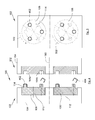
- the Fig. 1 shows a kit 100 for an injection molding machine for making a part by molding and to make an overmolding on it before ejection.
- the kit 100 includes a first set 102 and a second set 152.
- the first assembly 102 comprises a first support plate 104
- the second assembly 152 comprises a second support plate 154.
- the first support plate 104 is intended to be fixed on the first plate
- the second support plate 154 is intended to be fixed on the second plate, so that in the open position the two support plates 104 and 154 are spaced apart. one of the other and in the closed position the two support plates 104 and 154 are contiguous to one another.
- Each barrel 106, 108 is, on the one hand, rotatably mounted on said support plate 104 about an axis 110, 112 parallel to the direction of translation 180, and, on the other hand, carries at least two cavities 114
- the translation direction 180 is perpendicular to the plane of each support plate 104, 154.
- the second support plate 154 For each of the cavities 114, the second support plate 154 has a counter-cavity 164.
- Driving means for rotating each barrel 106, 108 are provided.
- the drive means allow the successive positioning of each cavity 114 vis-à-vis at least two different againstprints 164.
- These drive means can be hydraulic, pneumatic, electric.
- a molding machine comprising such a kit 100 makes it possible to mold a part and overmould the part thus molded.
- the first support plate 104 has on one of its faces, for each cylinder 106, 108, a housing 116 for housing said cylinder 106, 108.
- Each cylinder 106, 108 carries a plurality of cavities 114, each shaped so as to form part of a molding, and in particular the part not receiving overmolding.
- the second support plate 154 comprises, for each cavity 114, a counter-cavity 164.
- Each counter-cavity 164 is here shaped so as to produce another part of the part to be molded, and in particular the part receiving the overmoulding.
- the displacement of the trays and thus of the support plates 104 and 154 relative to one another can be achieved for example by placing jacks between the two plates.
- the Fig. 2 shows the second set 152 seen from the front.
- each barrel 106, 108 For each barrel 106, 108, six against-cavities 164a and 164b have been represented and they are distributed angularly regularly every 60 °. In the same way, six cavities 114 are provided on each barrel 106, 108.
- the counterprints 164a are the counterprints into which the molding is injected and the against-cavities 164b are the counterprints in which the overmoulding of the molded part is performed.
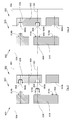
- the Fig. 3 shows the kit 100 in the closed position.
- Each pair consisting of a cavity 114 and a counter cavity 164a is fed by an injection molding machine of material intended to produce the part to be molded.
- the arrow 302 represents this injection.
- Each pair consisting of a cavity 114 and a recess 164b is fed by an injection molding machine for molding the mold. Arrow 304 represents this injection.
- the Fig. 4 shows the kit 100 in open position. This position follows the position shown on the Fig. 3 where a part 402 has been molded by an impression couple 114 / counter-cavity 164a and where a previously molded part 404 has been overmolded by an impression torque 114 / against-cavity 164b.
- the piece 404 is ejected while the piece 402 remains in place on the cylinder 106, 108 corresponding, here it remains on the cavity 114.
- the Fig. 5 shows the second set 102 seen from the front.
- each barrel 106, 108 is rotated by the drive means at an angle of 60 °.
- the arrows 502 represent these rotations.
- the angle of rotation may vary. The angle of rotation is equal to 360 ° divided by the number of counterprints 164.
- the kit 100 goes into closed position ( Fig. 3 ) but the fingerprints 114 have moved and each is now vis-à-vis another counterprint 164a, 164b. That is to say that the cavities 114 which, before the rotation 502, were opposite a recess 164a, are found, after the rotation 502, facing each other. a counterprint 164b, and vice versa.
- the empty cavities 114 are found opposite the cavities 164a and the cavities 114 bearing the patches 402 are found opposite the cavities 164b.
- At least one of the cavity 114 / against impression cavity 164a is a molding torque of the workpiece, and at least one of the other pairs 114 / counterpart 164b is an overmolding torque of the part thus molded.
- counterprints 164 which are angularly distributed uniformly and intercalated in two groups of against-prints 164a and 164b.
- the number of molding torques is equal to the number of overmolding torques.
- each overmoulding there is at least one counter-cavity 164a for molding the part 402 and for each overmolding, there is at least one counter-cavity 164b for producing said overmolding.
- the number of counterprints 164b is equal to the number of counterprints 164a.
- the against-imprints 164a are grouped on the same side of an axis of symmetry and the against-imprints 164b are grouped on the other side of the axis of symmetry.
- the angle of rotation of the barrels 106 and 108 is then different, for example 180 °.
- the Fig. 6 shows a kit 600 for an injection molding machine according to another embodiment of the invention.
- the injection molding machine makes it possible to mold two elements and to assemble them in order to produce the final molding.
- Kit 600 includes a first set 602 and a second set 652.
- the first assembly 602 includes a first support plate 604 and the second assembly 652 comprises a second support plate 654.
- the first support plate 604 is intended to be fixed on the first plate
- the second support plate 654 is intended to be fixed on the second plate, so that in the open position the two support plates 604 and 654 are spaced apart. one of the other and in the closed position the two support plates 604 and 654 are contiguous to one another.
- a cylinder 606 of a first type is put in place and for the second plate 654, a cylinder 656 of a second type is put in place.
- Each barrel 606, 656, is, on the one hand, rotatably mounted on the support plate 604, 654 considered about an axis 610, 660 parallel to the translation direction 180, and, on the other hand, to the minus two imprints respectively referenced 614a and 614c, 664a-b.
- a counter-cavity 664a, 664c is disposed on the second support plate 654, either on the barrel 656 of the second type, or directly on the second support plate 654.
- a counter-cavity 614a, 614b is disposed on the first support plate 604, or on the barrel 606 of the first type, either directly on the first support plate 604.
- the translation direction 180 is perpendicular to the plane of each support plate 604, 654.
- the cylinder 606 of the first type carries two cavities 614a and 614c
- the barrel 656 of the second type carries two cavities 664a-b.
- each barrel 606, 656 one of the cavities 614a of the barrel 606 of the first type is vis-à- screw of one of the counterprints 664a of the barrel 656 of the second type.
- This imprint 614a of the barrel 606 of the first type and this counterprint 664a of the barrel 656 of the second type constitute an assembly torque of the two molded elements.
- each barrel 606, 656 the other footprint 614c of the barrel 606 of the first type and the associated counter-cavity 664c of the second support plate 654 constitute a molding torque of a first element of the piece to molding, and the other 664b imprint of the barrel 656 of the second type and the associated counterpart 614b of the first support plate 604 constitute a molding torque of a second element of the workpiece.
- the counter-cavity 614b and the counter-cavity 664c are fixed on the support plates 604 and 654.
- the Fig. 7 shows the kit 600 in closed position.
- Each pair consisting of the counter-cavity 614b and the associated footprint 664b or the footprint 614c and associated counter-cavity 664c, that is to say one of the molding shapes 614b, 664c is not on a barrel 606, 656 is a molding torque which is fed by an injection molding machine for producing the elements to be molded.
- the arrow 702 represents this injection intended to mold the first element and the arrow 704 represents this injection intended to mold the second element.
- the arrow 706 represents an assembly force which is generated for the assembly torque (614a, 664a) in order to assemble the first element and the second element previously molded in order to produce the final part.
- This assembly force can be generated for example by a pad driven in motion hydraulically, pneumatically or electrically, or by a jet of pressurized air that pushes one of the two elements in the other.
- the Fig. 8 shows kit 600 in open position. This position follows the position shown on the Fig. 7 wherein a first member 802 has been molded by the molding torque (614c, 664c) of the first member, and a second member 804 has been molded by the molding torque (614b, 664b) of the second member.
- the assembled part 806 is ejected while the first element 802 and the second element 804 remain fixed on the cylinder 606, 656 corresponding.
- the Fig. 10a shows the first set 602 seen from the front
- the Fig. 10b shows the second set 652 seen from the front.
- each barrel 606, 656 is rotated by drive means at an angle of 180 °.
- Arrows 1002a and 1002b represent these rotations.
- the kit 600 goes into closed position ( Fig. 7 ) but the footprints 614a and 614c, and 664a-b have moved.
- Each footprint 614a, 614c is now facing another counterprint respectively referenced 664c, 664b, and each footprint 664a-b is now vis-à-vis another counterprint respectively referenced 614b, 614c.
- the Fig. 9 shows the kit 600 at the end of the rotations of the barrels 606 and 656 and before the return to the closed position.
- the empty cavity 614a and the empty counter-cavity 614b are found facing each other against an empty counterprint referenced 664c and an empty cavity referenced 664a.
- the footprint 614c carrying the first element 802 is found vis-à-vis the counter 664b bearing the second element 804.
- the kit 600 can then go into closed position ( Fig. 7 ) where two new elements 802 and 804 are molded and a new assembled part 806 is made.
- the Fig. 11 shows a kit 1100 for an injection molding machine according to another embodiment of the invention.
- the injection molding machine makes it possible to mold two elements, to overmould at least one of them and to assemble them in order to produce the part to be molded.
- Kit 1100 includes a first set 1102 and a second set 1152.
- the first assembly 1102 includes a first support plate 1104, the second assembly 1152 includes a second support plate 1154.
- the first support plate 1104 is intended to be fixed on the first plate
- the second support plate 1154 is intended to be fixed on the second plate, so that in the open position the two support plates 1104 and 1154 are spaced from each other and in the closed position the two support plates 104 and 1154 are contiguous to one another.
- a barrel 1106 of a first type is put in place and for the second plate 1154, a barrel 1156 of a second type is put in place.
- Each barrel 1106, 1156 is, on the one hand, rotatably mounted on the support plate 1104, 1154 considered around an axis 1110, 1160 parallel to the translation direction 180, and, on the other hand, door to minus two imprints respectively referenced 1114a and 1114d, 1164a-c.
- a counter-cavity 1164a, 1164d is disposed on the second support plate 1154, either on the barrel 1156 of the second type, or directly on the second support plate 1154.
- a counter-cavity 1114a-c is disposed on the first support plate 1104, either on the barrel 1106 of the first type, or directly on the first support plate 1104.
- the translational direction 180 is perpendicular to the plane of each support plate 1104, 1154 .
- the barrel 1106 of the first type carries two cavities 1114a and 1114d
- the barrel 1156 of the second type carries three cavities 1164a-c.
- the fingerprints 1164b and 1164c are seen in an offset section.
- one of the cavities 1114a of the barrel 1106 of the first type is vis-à- screw of one of the counterprints 1164a of the barrel 1156 of the second type.
- This impression 1114a of the barrel 1106 of the first type and this counterprint 1164a of the barrel 1156 of the second type constitute an assembly torque of the first molded element and the second molded and overmolded element.
- each barrel 1106, 1156 the other recess 1114d of the barrel 1106 of the first type and the associated recess 1164d of the second support plate 1154 constitute a molding torque of a first element of the barrel. molded.
- One of the other imprints here the imprint 1164b, the barrel 1156 of the second type and the counterpart 1114b associated with the first support plate 1104 constitute a molding torque of a second element of the part to be molded.
- One of the other indentations, here the cavity 1164c, of the barrel 1156 of the second type and the counterpart 1114c associated with the first support plate 1104 constitute an overmolding torque of the second element.
- the counterprints 1114b and 1114c, and the counter-cavity 1164d are fixed on the support plates 1104 and 1154.
- the counterprints 1114b and 1114c are seen in an offset section.
- the Fig. 12 shows the kit 1100 in closed position.
- the arrow 1202 represents this injection intended to mold the first element and the arrow 1204 represents this injection intended to mold the second element.
- the arrow 1208 represents this injection intended to make the overmolding of the second element.
- the arrow 1206 represents an assembly force that is generated for the assembly torque (1114a, 1164a) to effect assembly of the first member and the second member to produce the final piece.
- the Fig. 13 shows the kit 1100 in open position. This position follows the position shown on the Fig. 12 wherein a first member 1302 has been molded by the molding torque (1114d, 1164d) of the first member, wherein a second member 1304 has been molded by the molding torque (1114b, 1164b) of the second member, and wherein a second member 1308 previously molded by the molding torque of the second element, was overmolded by the overmolding torque (1114c, 1164c).
- the part 1306 assembled from a first element 1302 and a second overmoulded element 1308 is ejected while the first element 1302 and the second molded element 1304 and the second overmolded element 1308 remain fixed on the barrel 1106 , Corresponding 1156.
- the Fig. 15a shows the first set 1102 seen from the front
- the Fig. 15b shows the second set 1152 seen from the front.
- the kit 1100 goes into closed position ( Fig. 12 ) but the fingerprints 1114a and 1114d, and 1164a-c have moved.
- Each footprint 1114a, 1114d is now facing another counterprint respectively referenced 1164d, 1164c, and each footprint 1164a-c is now vis-à-vis another counterprint respectively referenced 1114b, 1114c, 1114d.
- the Fig. 14 shows the kit 1100 at the end of the rotations of the barrels 1106 and 1156 and before the return to the closed position.
- the empty cavity 1114a and the empty counterprint 1114b are found opposite each other against an empty counterprint referenced 1164d and an empty footprint referenced 1164a.
- the cavity 1114d carrying the first element 1302 is found vis-à-vis the counter 1164c carrying the second element 1308 overmoulded.
- the cavity 1164b carrying the second molded element 1304 is found opposite the counter 1114c.
- first element 1302 must be overmolded before being assembled, it is possible to introduce another imprint on the barrel of the first type and an associated counterprint on the second support plate. The rotation of the barrel of the first type is then 120 ° with each rotation.
- the kit 1100 can then go into closed position ( Fig. 12 ) where two new elements 1302 and 1304 are molded, where a new second element 1308 is overmolded and a new assembled part 1306 is made.
- the directions of rotation of the different barrels may be different.
- the number of impressions and the number of counterprints, as well as their angular distributions may vary.
Description
La présente invention concerne un kit pour une machine de moulage par injection comportant au moins un barillet, ainsi qu'une machine de moulage par injection comportant un tel kit.The present invention relates to a kit for an injection molding machine comprising at least one barrel, and an injection molding machine comprising such a kit.
Le document
Pour mouler une multitude de pièces, par exemple du type bouchon de récipient, une machine de moulage par injection de l'état de la technique comporte une première plaque dont l'une des faces porte une pluralité de premières formes de moulage et une deuxième plaque dont l'une des faces porte une pluralité de deuxièmes formes de moulage. Chaque première forme de moulage est associée à une deuxième forme de moulage pour former un volume dans lequel du matériau est injecté afin de réaliser la pièce à mouler.In order to mold a multitude of parts, for example of the container cap type, a state-of-the-art injection molding machine comprises a first plate, one of the faces of which carries a plurality of first molding shapes and a second plate. one of the faces of which carries a plurality of second molding shapes. Each first form of molding is associated with a second form of molding to form a volume into which material is injected in order to produce the piece to be molded.
Les deux plaques sont mobiles l'une par rapport à l'autre en coulissement entre une position fermée et une position ouverte selon une direction de translation sensiblement orthogonale au plan des deux faces.The two plates are movable relative to each other in sliding between a closed position and an open position in a direction of translation substantially orthogonal to the plane of the two faces.
Dans la position fermée, les deux faces sont en contact l'une contre l'autre de manière à ce que les premières formes de moulage et les deuxièmes formes de moulage correspondantes soient en vis-à-vis. Chacun des volumes est alors rempli par le matériau de moulage souhaité.In the closed position, the two faces are in contact with each other so that the first molding shapes and the second forms of corresponding molding are vis-à-vis. Each of the volumes is then filled with the desired molding material.
Dans la position ouverte, les deux plaques sont distantes l'une de l'autre pour permettre l'éjection des pièces moulées.In the open position, the two plates are spaced from each other to allow ejection of the molded parts.
Dans le cas de l'état de la technique, lorsqu'un surmoulage de la pièce moulée est nécessaire, chaque pièce doit être mise en place dans un autre appareil où elle est surmoulée.In the case of the state of the art, when an overmolding of the molded part is necessary, each piece must be put in place in another apparatus where it is overmolded.
Lorsqu'un premier élément moulé doit être assemblé à un deuxième élément moulé afin de réaliser la pièce finale à mouler, une autre machine doit être mise en place pour récupérer les premiers et les deuxièmes éléments et les assembler.When a first molded member is to be assembled to a second molded member to provide the final moldable part, another machine must be put in place to retrieve the first and second members and assemble them.
Que ce soit dans le cas du surmoulage ou dans le cas de l'assemblage, il est nécessaire de prévoir une autre machine pour parvenir à la pièce finale. De telles machines sont coûteuses aussi bien à l'achat qu'à l'entretien.Whether in the case of overmolding or in the case of assembly, it is necessary to provide another machine to reach the final part. Such machines are expensive both for purchase and maintenance.
Il est donc souhaitable de trouver une machine de moulage par injection qui permet de réaliser ces différentes opérations et qui a un coût de revient réduit.It is therefore desirable to find an injection molding machine which allows these different operations to be carried out and which has a reduced cost price.
Un objet de la présente invention est de proposer un kit pour une machine de moulage par injection qui ne présente pas les inconvénients de l'art antérieur et qui en particulier permet de réaliser des pièces surmoulées et/ou assemblées de manière simple et peu onéreuse.An object of the present invention is to provide a kit for an injection molding machine which does not have the drawbacks of the prior art and which in particular makes it possible to produce overmoulded parts and / or assembled in a simple and inexpensive manner.
A cet effet, est proposé un kit pour une machine de moulage par injection de pièces moulées, la machine de moulage comportant un premier plateau et un deuxième plateau, le kit comportant:
- une première plaque support destinée à être fixée sur ledit premier plateau,
- une deuxième plaque support destinée à être fixée sur ledit deuxième plateau, les deux plateaux étant prévus pour être mobiles l'un par rapport à l'autre en coulissement selon une direction de translation de manière à prendre successivement une position ouverte dans laquelle les deux plaques support sont distantes l'une de l'autre et une position fermée dans laquelle les deux plaques support sont accolées l'une à l'autre,
- pour la première plaque support, au moins un barillet d'un premier type, monté mobile en rotation sur ladite première plaque support autour d'un axe perpendiculaire au plan de ladite première plaque support, et portant au moins deux empreintes,
- pour la deuxième plaque support, au moins un barillet d'un deuxième type, monté mobile en rotation sur ladite deuxième plaque support autour d'un axe perpendiculaire au plan de ladite deuxième plaque support, et portant au moins trois empreintes,
- pour chacune desdites empreintes, une contre-empreinte disposée sur l'autre plaque support,
- des moyens d'entraînement destinés à déplacer en rotation chaque barillet pour permettre le positionnement successif de chaque empreinte en vis-à-vis d'au moins deux contre-empreintes différentes et de manière à ce que, à chaque déplacement en rotation de chaque barillet, l'une des empreintes dudit barillet du premier type soit en vis-à-vis de l'une des contre-empreintes dudit barillet du deuxième type et de manière à ce que, à chaque déplacement en rotation de chaque barillet, l'autre empreinte dudit barillet du premier type et la contre-empreinte associée de ladite deuxième plaque support constituent un couple de moulage d'un premier élément de la pièce à mouler, l'une des autres empreintes dudit barillet du deuxième type et la contre-empreinte associée de ladite première plaque support constituent un couple de moulage d'un deuxième élément de la pièce à mouler, l'une des autres empreintes dudit barillet du deuxième type et la contre-empreinte associée de ladite première plaque support constituent un couple de surmoulage dudit deuxième élément, et ledit couple empreinte dudit barillet du premier type et contre-empreinte dudit barillet du deuxième type constituent un couple d'assemblage dudit premier élément ainsi moulé et dudit deuxième élément ainsi moulé et surmoulé.
- a first support plate intended to be fixed on said first plate,
- a second support plate intended to be fixed on said second plate, the two plates being designed to be movable relative to each other in sliding in a translation direction so as to take successively an open position in which the two plates support are spaced from each other and a closed position in which the two support plates are contiguous to one another,
- for the first support plate, at least one barrel of a first type, rotatably mounted on said first support plate about an axis perpendicular to the plane of said first support plate, and carrying at least two cavities,
- for the second support plate, at least one cylinder of a second type, rotatably mounted on said second support plate about an axis perpendicular to the plane of said second support plate, and carrying at least three indentations,
- for each of said indentations, a counterprint disposed on the other support plate,
- drive means for rotating each barrel to allow the successive positioning of each fingerprint vis-à-vis at least two different against-imprints and so that at each rotational movement of each barrel , one of the fingerprints of said barrel of the first type is vis-à-vis one of the counterprints of said barrel of the second type and so that, with each rotational movement of each barrel, the other impression of said barrel of the first type and the associated counterprint of said second support plate constitute a molding torque of a first element of the part to be molded, one of the other impressions of said barrel of the second type and the associated counterprint of said first support plate constitute a molding torque of a second element of the part to be molded, one of the other impressions of said cylinder of the second type and the associated counterprint of said first support plate constitute an overmolding torque of said second element, and said torque impression of said cylinder of the first type and counterprint of said cylinder of the second type constitute an assembly torque of said first element thus molded and said second element thus molded and molded.
L'invention propose également une machine de moulage par injection de pièces moulées comportant:
- un premier plateau,
- un deuxième plateau, les deux plateaux étant prévus pour être mobiles l'un par rapport à l'autre en coulissement selon une direction de translation, et
- un kit selon la variante précédente.
- a first plateau,
- a second plate, the two plates being designed to be movable relative to one another in sliding in a direction of translation, and
- a kit according to the previous variant.
Les caractéristiques de l'invention mentionnées ci-dessus, ainsi que d'autres, apparaîtront plus clairement à la lecture de la description suivante d'un exemple de réalisation, ladite description étant faite en relation avec les dessins joints, parmi lesquels :
- la
Fig. 1 représente une vue en coupe selon la ligne I-I de laFig. 2 , d'un kit pour une machine de moulage par injection selon un premier mode de réalisation de l'invention en position ouverte, - la
Fig. 2 est une vue de face d'une plaque du kit de laFig. 1 , - la
Fig. 3 est une vue similaire à celle de laFig. 1 en position fermée, - la
Fig. 4 est une vue similaire à celle de laFig. 1 lors de l'éjection des pièces moulées, - la
Fig. 5 est une vue de face d'une plaque du kit de laFig. 1 lors de la rotation des barillets, - la
Fig. 6 représente une vue de côté d'un kit pour une machine de moulage par injection selon un deuxième mode de réalisation de l'invention en position ouverte, - les
Figs. 7 ,8 et 9 sont des vues similaires à laFig. 6 pour des étapes de moulage différentes, - la
Fig. 10a est une vue de face d'une plaque du kit de laFig. 6 lors de la rotation des barillets, - la
Fig. 10b est une vue de face d'une plaque du kit de laFig. 6 lors de la rotation des barillets, - la
Fig. 11 représente une vue de côté d'un kit pour une machine de moulage par injection selon un troisième mode de réalisation de l'invention en position ouverte, - les
Figs. 12 ,13 et 14 sont des vues similaires à laFig. 11 pour des étapes de moulage différentes, - la
Fig. 15a est une vue de face d'une plaque du kit de laFig. 11 lors de la rotation des barillets, et - la
Fig. 15b est une vue de face d'une plaque du kit de laFig. 11 lors de la rotation des barillets.
- the
Fig. 1 represents a sectional view along the line II of theFig. 2 of a kit for an injection molding machine according to a first embodiment of the invention in an open position, - the
Fig. 2 is a front view of a plate from the kit of theFig. 1 , - the
Fig. 3 is a view similar to that of theFig. 1 in closed position, - the
Fig. 4 is a view similar to that of theFig. 1 during the ejection of the molded parts, - the
Fig. 5 is a front view of a plate from the kit of theFig. 1 during the rotation of the barrels, - the
Fig. 6 is a side view of a kit for an injection molding machine according to a second embodiment of the invention in an open position, - the
Figs. 7 ,8 and 9 are views similar to theFig. 6 for different molding steps, - the
Fig. 10a is a front view of a plate from the kit of theFig. 6 during the rotation of the barrels, - the
Fig. 10b is a front view of a plate from the kit of theFig. 6 during the rotation of the barrels, - the
Fig. 11 is a side view of a kit for an injection molding machine according to a third embodiment of the invention in an open position, - the
Figs. 12 ,13 and 14 are views similar to theFig. 11 for different molding steps, - the
Fig. 15a is a front view of a plate from the kit of theFig. 11 during the rotation of the barrels, and - the
Fig. 15b is a front view of a plate from the kit of theFig. 11 during the rotation of the barrels.
Dans l'ensemble des Figs., les kits sont montés sur des machines de moulage par injection qui sont reliées à une presse à injection non représentée qui alimente les volumes délimités par les empreintes et les contre-empreintes en matériaux de moulage.In all of the Figs., The kits are mounted on injection molding machines which are connected to a not shown injection molding machine which feeds the volumes delimited by the imprints and the against-imprints of molding materials.
Dans la description qui suit, le terme 'empreinte' représente une forme de moulage disposée sur un barillet et le terme 'contre-empreinte' représente la forme de moulage associée complémentaire de ladite empreinte. Ainsi, une forme de moulage disposée sur un barillet peut être dénommée 'empreinte' et 'contre-empreinte'. Une forme de moulage disposée directement sur une plaque support est dénommée 'contre-empreinte'.In the description which follows, the term "imprint" represents a form of molding disposed on a barrel and the term "counterprint" represents the associated complementary molding form of said imprint. Thus, a form of molding disposed on a barrel may be called 'imprint' and 'counterprint'. A form of molding arranged directly on a support plate is called 'against-imprint'.
La machine de moulage comporte un premier plateau et un deuxième plateau qui sont prévus pour être mobiles l'un par rapport à l'autre en coulissement selon une direction de translation 180 de manière à prendre successivement une position ouverte et une position fermée.The molding machine comprises a first plate and a second plate which are adapted to be movable relative to one another in sliding manner according to a
La
Le premier ensemble 102 comporte une première plaque support 104, le deuxième ensemble 152 comporte une deuxième plaque support 154.The
La première plaque support 104 est destinée à être fixée sur le premier plateau, et la deuxième plaque support 154 est destinée à être fixée sur le deuxième plateau, de manière à ce que en position ouverte les deux plaques support 104 et 154 sont distantes l'une de l'autre et en position fermée les deux plaques support 104 et 154 sont accolées l'une à l'autre.The
Pour au moins une desdites plaques support 104, 154, ici la première plaque support 104, au moins un barillet 106, 108 est mis en place (ici deux barillets sont mis en place).For at least one of said
Chaque barillet 106, 108 est, d'une part, monté mobile en rotation sur ladite plaque support 104 autour d'un axe 110, 112 parallèle à la direction de translation 180, et, d'autre part, porte au moins deux empreintes 114. La direction de translation 180 est perpendiculaire au plan de chaque plaque support 104, 154.Each
Pour chacune des empreintes 114, la deuxième plaque support 154 présente une contre-empreinte 164.For each of the
Des moyens d'entraînement destinés à déplacer en rotation chaque barillet 106, 108 sont prévus. Les moyens d'entraînement permettent le positionnement successif de chaque empreinte 114 en vis-à-vis d'au moins deux contre-empreintes 164 différentes. Ces moyens d'entraînement peuvent être hydrauliques, pneumatiques, électriques.Driving means for rotating each
Comme cela est expliqué ci-après, une machine de moulage comportant un tel kit 100 permet de mouler une pièce et de surmouler la pièce ainsi moulée.As explained below, a molding machine comprising such a
La première plaque support 104 présente sur l'une de ses faces, pour chaque barillet 106, 108, un logement 116 destiné à loger ledit barillet 106, 108.The
Chaque barillet 106, 108 porte une pluralité d'empreintes 114, chacune conformée de manière à réaliser une partie d'une pièce à mouler, et, en particulier, la partie ne recevant pas de surmoulage.Each
La deuxième plaque support 154 comporte pour chaque empreinte 114, une contre-empreinte 164. Chaque contre-empreinte 164 est ici conformée de manière à réaliser une autre partie de la pièce à mouler, et, en particulier, la partie recevant le surmoulage.The
Le déplacement des plateaux et donc des plaques support 104 et 154 l'un par rapport à l'autre, peut être réalisé par exemple par la mise en place de vérins entre les deux plateaux.The displacement of the trays and thus of the
Le fait que les plaques support 104 et 154 ne supportent qu'un déplacement en translation et non un déplacement en rotation permet d'assurer une bonne mise en place des empreintes 114 et des contre-empreintes 164.The fact that the
La
Pour chaque barillet 106, 108, six contre-empreintes 164a et 164b ont été représentées et elles sont réparties angulairement de manière régulière tous les 60°. De la même manière, six empreintes 114 sont prévues sur chaque barillet 106, 108.For each
Les contre-empreintes 164a sont les contre-empreintes dans lesquelles la pièce à mouler est injectée et les contre-empreintes 164b sont les contre-empreintes dans lesquelles le surmoulage de la pièce ainsi moulée est réalisé.The
La
Chaque couple constitué d'une empreinte 114 et d'une contre-empreinte 164a est alimenté par une presse à injection en matériau destiné à réaliser la pièce à mouler. La flèche 302 représente cette injection.Each pair consisting of a
Chaque couple constitué d'une empreinte 114 et d'une contre-empreinte 164b est alimenté par une presse à injection en matériau destiné à réaliser le surmoulage de la pièce à mouler. La flèche 304 représente cette injection.Each pair consisting of a
La
En position ouverte, la pièce 404 est éjectée tandis que la pièce 402 reste en place sur le barillet 106, 108 correspondant, ici elle reste sur l'empreinte 114.In the open position, the
La
En position ouverte, chaque barillet 106, 108 est déplacé en rotation par les moyens d'entraînement sur un angle de 60°. Les flèches 502 représentent ces rotations. Selon le nombre de contre-empreintes 164, l'angle de rotation peut varier. L'angle de rotation est égal à 360° divisé par le nombre de contre-empreintes 164.In the open position, each
Après cette rotation 502, le kit 100 passe en position fermée (
Les empreintes 114 vides se retrouvent en vis-à-vis des contre-empreintes 164a et les empreintes 114 portant les pièces 402 se retrouvent en vis-à-vis des contre-empreintes 164b.The
Ainsi, à chaque déplacement en rotation de chaque barillet 106, 108, au moins l'un des couples empreinte 114 / contre-empreinte 164a constitue un couple de moulage de la pièce à mouler, et au moins l'un des autres couples empreinte 114 / contre-empreinte 164b constitue un couple de surmoulage de la pièce ainsi moulée.Thus, with each rotational movement of each
Dans le cas d'un surmoulage simple, il y a un nombre pair de contre-empreintes 164, qui sont réparties angulairement de manière uniforme et intercalée en deux groupes de contre-empreintes 164a et 164b. Les contre-empreintes 164a du premier groupe servant au moulage et les contre-empreintes 164b du deuxième groupe servant au surmoulage. Le nombre de couples de moulage est égal au nombre de couples de surmoulage.In the case of a simple overmolding, there is an even number of
Dans le cas d'un surmoulage multiple, il y a au moins une contre-empreinte 164a pour réaliser le moulage de la pièce 402 et pour chaque surmoulage, il y a au moins une contre-empreinte 164b pour réaliser ledit surmoulage. Pour chaque surmoulage, le nombre de contre-empreintes 164b est égal au nombre de contre-empreintes 164a.In the case of a multiple overmoulding, there is at least one counter-cavity 164a for molding the
Bien sûr, il est possible de répartir les groupes différemment. Par exemple, les contre-empreintes 164a sont regroupées d'un même côté d'un axe de symétrie et les contre-empreintes 164b sont regroupées de l'autre côté de l'axe de symétrie. L'angle de rotation des barillets 106 et 108 est alors différent, par exemple 180°.Of course, it is possible to divide the groups differently. For example, the against-
Le procédé de moulage et de surmoulage de la pièce 404 mis en oeuvre avec la machine de moulage comportant le kit 100 comporte, à partir de la position fermée des deux plaques support 104 et 154:
- une étape de surmoulage de la pièce 404 précédemment moulée par un couple de surmoulage constitué d'une empreinte 114 et d'une contre-
empreinte 164b, - une étape de moulage de la pièce 402 par un couple de moulage constitué d'une empreinte 114 et d'une contre-empreinte 164a,
- une étape de passage en position ouverte des deux plaques support 104
et 154, - une étape d'éjection de la pièce 402 ainsi surmoulée,
- une étape de rotation de chaque barillet 106, 108 de manière à amener, d'une part,
une empreinte 114 d'une position en vis-à-vis d'une contre-empreinte 164a à une position en vis-à-vis d'une contre-empreinte 164b et, d'autre part,une empreinte 114 d'une position en vis-à-vis d'une contre-empreinte 164b à une position en vis-à-vis d'une contre-empreinte 164a, - une étape de passage en position fermée des deux plaques support 104
et 154, et - une étape de bouclage sur l'étape de surmoulage.
- an overmoulding step of the
piece 404 previously molded by an overmoulding pair consisting of acavity 114 and acounterprint 164b, - a step of molding the
part 402 by a molding pair consisting of acavity 114 and acavity 164a, - a step of passing in the open position of the two
support plates - a step of ejection of the
part 402 and overmolded, - a step of rotation of each
barrel cavity 114 of a position vis-à-vis acounter cavity 164a to a position vis-à-vis arecess 164b and, on the other hand, arecess 114 of a position opposite arecess 164b at a position opposite arecess 164a, - a step of passage in the closed position of the two
support plates - a looping step on the overmolding step.
La
Le kit 600 comporte un premier ensemble 602 et un deuxième ensemble 652.
Le premier ensemble 602 comporte une première plaque support 604 le deuxième ensemble 652 comporte une deuxième plaque support 654.The
La première plaque support 604 est destinée à être fixée sur le premier plateau, et la deuxième plaque support 654 est destinée à être fixée sur le deuxième plateau, de manière à ce que en position ouverte les deux plaques support 604 et 654 sont distantes l'une de l'autre et en position fermée les deux plaques support 604 et 654 sont accolées l'une à l'autre.The
Pour la première plaque 604, un barillet 606 d'un premier type est mis en place et pour la deuxième plaque 654, un barillet 656 d'un deuxième type est mis en place.For the
Chaque barillet 606, 656, est, d'une part, monté mobile en rotation sur la plaque support 604, 654 considérée autour d'un axe 610, 660 parallèle à la direction de translation 180, et, d'autre part, porte au moins deux empreintes respectivement référencées 614a et 614c, 664a-b. Pour chacune des empreintes 614a et 614c, une contre-empreinte 664a, 664c est disposée sur la deuxième plaque support 654, soit sur le barillet 656 du deuxième type, soit directement sur la deuxième plaque support 654. Pour chacune des empreintes 664a et 664b, une contre-empreinte 614a, 614b est disposée sur la première plaque support 604, soit sur le barillet 606 du premier type, soit directement sur la première plaque support 604. La direction de translation 180 est perpendiculaire au plan de chaque plaque support 604, 654.Each
Dans le mode de réalisation des
Pour assurer l'assemblage de deux éléments préalablement moulés, et comme cela est explicité ci-après, à chaque déplacement en rotation de chaque barillet 606, 656, l'une des empreintes 614a du barillet 606 du premier type est en vis-à-vis de l'une des contre-empreintes 664a du barillet 656 du deuxième type. Cette empreinte 614a du barillet 606 du premier type et cette contre-empreinte 664a du barillet 656 du deuxième type constituent un couple d'assemblage des deux éléments moulés.To ensure the assembly of two previously molded elements, and as explained below, at each rotational movement of each
A chaque déplacement en rotation de chaque barillet 606, 656, l'autre empreinte 614c du barillet 606 du premier type et la contre-empreinte 664c associée de la deuxième plaque support 654 constituent un couple de moulage d'un premier élément de la pièce à mouler, et l'autre empreinte 664b du barillet 656 du deuxième type et la contre-empreinte 614b associée de la première plaque support 604 constituent un couple de moulage d'un deuxième élément de la pièce à mouler.At each rotational movement of each
La contre-empreinte 614b et la contre-empreinte 664c sont fixes sur les plaques support 604 et 654.The counter-cavity 614b and the counter-cavity 664c are fixed on the
La
Chaque couple constitué de la contre-empreinte 614b et de l'empreinte 664b associée ou de l'empreinte 614c et de la contre-empreinte 664c associée, c'est-à-dire dont l'une des formes de moulage 614b, 664c n'est pas sur un barillet 606, 656 constitue un couple de moulage qui est alimenté par une presse à injection en matériau destiné à réaliser les éléments à mouler. La flèche 702 représente cette injection destinée à mouler le premier élément et la flèche 704 représente cette injection destinée à mouler le deuxième élément.Each pair consisting of the counter-cavity 614b and the associated
La flèche 706 représente une force d'assemblage qui est générée pour le couple d'assemblage (614a, 664a) afin de réaliser l'assemblage du premier élément et du deuxième élément préalablement moulés afin de réaliser la pièce définitive.The
Cette force d'assemblage peut être générée par exemple par un plot entraîné en mouvement de manière hydraulique, pneumatique ou électrique, ou par un jet d'air sous pression qui vient pousser l'un des deux éléments dans l'autre.This assembly force can be generated for example by a pad driven in motion hydraulically, pneumatically or electrically, or by a jet of pressurized air that pushes one of the two elements in the other.
La
En position ouverte, la pièce 806 assemblée est éjectée tandis que le premier élément 802 et le deuxième élément 804 restent fixés sur le barillet 606, 656 correspondant.In the open position, the assembled
La
En position ouverte, chaque barillet 606, 656 est déplacé en rotation par des moyens d'entraînement sur un angle de 180°. Les flèches 1002a et 1002b représentent ces rotations.In the open position, each
Après ces rotations 1002a et 1002b, le kit 600 passe en position fermée (
La
L'empreinte vide 614a et la contre-empreinte vide 614b se retrouvent en vis-à-vis respectivement d'une contre-empreinte vide référencée 664c et d'une empreinte vide référencée 664a. L'empreinte 614c portant le premier élément 802 se retrouve en vis-à-vis de la contre-empreinte 664b portant le deuxième élément 804.The
Le kit 600 peut alors passer en position fermée (
Le procédé de moulage et d'assemblage de la pièce 806 à partir du premier élément 802 et du deuxième élément 804 mis en oeuvre avec la machine de moulage comportant le kit 600 comporte, à partir de la position fermée des deux plaques support 604 et 654:
- une étape d'assemblage d'un
premier élément 802 précédemment moulé et d'un deuxième élément 804 précédemment moulé par un couple d'assemblage constitué d'une empreinte 614a et d'une contre-empreinte 664a, - une étape de moulage du
premier élément 802 par un couple de moulage constitué d'une empreinte 614c et d'une contre-empreinte 664c, - une étape de moulage du deuxième élément 804 par un couple de moulage constitué d'une empreinte 664b et d'une contre-
empreinte 614b, - une étape de passage en position ouverte des deux plaques support 104
et 154, - une étape d'éjection de la pièce 806 ainsi assemblée,
- une étape de rotation de chaque barillet 606, 656, de manière à amener:
- l'empreinte 614c portant le
premier élément 802 d'une position en vis-à-vis de la contre-empreinte 664c à une position en vis-à-vis de la contre-empreinte 664b portant le deuxième élément 804, - l'empreinte 664b portant le deuxième élément 804 d'une position en vis-à-vis de la contre-
empreinte 614b à une position en vis-à-vis de la contre-empreinte 614c portant lepremier élément 802, - l'empreinte 614a qui portait le
premier élément 802 ainsi assemblé d'une position en vis-à-vis de la contre-empreinte 664a qui portait le deuxième élément 804 ainsi assemblé à une position en vis-à-vis de la contre-empreinte 664c, et - l'empreinte 664a qui portait le deuxième élément 804 ainsi assemblé d'une position en vis-à-vis de la contre-empreinte 614a qui portait le
premier élément 802 ainsi assemblé à une position en vis-à-vis de la contre-empreinte 614b,
- l'empreinte 614c portant le
- une étape de passage en position fermée des deux plaques support 604
et 654, et - une étape de bouclage sur l'étape d'assemblage.
- a step of assembling a
first element 802 previously molded and asecond element 804 previously molded by an assembly torque consisting of acavity 614a and a counterprint 664a, - a molding step of the
first element 802 by a molding pair consisting of acavity 614c and acavity 664c, - a step of molding the
second element 804 by a molding pair consisting of acavity 664b and acounterprint 614b, - a step of passing in the open position of the two
support plates - an ejection step of the
piece 806 thus assembled, - a step of rotation of each
barrel - the
impression 614c carrying thefirst element 802 from a position vis-à-vis the counter-cavity 664c at a position vis-à-vis the counter-cavity 664b carrying thesecond element 804, - the
cavity 664b bearing thesecond element 804 from a position opposite thecavity 614b at a position opposite thecavity 614c bearing thefirst element 802, - the
impression 614a which carried thefirst element 802 thus assembled from a position vis-à-vis the counter-cavity 664a which carried thesecond element 804 thus assembled to a position vis-à-vis the counterprint 664c, and - the
impression 664a which carried thesecond element 804 thus assembled from a position vis-à-vis the counter-cavity 614a which carried thefirst element 802 thus assembled to a position vis-à-vis the counterprint 614b,
- the
- a step of passage in the closed position of the two
support plates - a looping step on the assembly step.
La
Le kit 1100 comporte un premier ensemble 1102 et un deuxième ensemble 1152.
Le premier ensemble 1102 comporte une première plaque support 1104, le deuxième ensemble 1152 comporte une deuxième plaque support 1154.The
La première plaque support 1104 est destinée à être fixée sur le premier plateau, et la deuxième plaque support 1154 est destinée à être fixée sur le deuxième plateau, de manière à ce que en position ouverte les deux plaques support 1104 et 1154 sont distantes l'une de l'autre et en position fermée les deux plaques support 104 et 1154 sont accolées l'une à l'autre.The
Pour la première plaque 1104, un barillet 1106 d'un premier type est mis en place et pour la deuxième plaque 1154, un barillet 1156 d'un deuxième type est mis en place.For the
Chaque barillet 1106, 1156, est, d'une part, monté mobile en rotation sur la plaque support 1104, 1154 considérée autour d'un axe 1110, 1160 parallèle à la direction de translation 180, et, d'autre part, porte au moins deux empreintes respectivement référencées 1114a et 1114d, 1164a-c. Pour chacune des empreintes 1114a et 1114d, une contre-empreinte 1164a, 1164d est disposée sur la deuxième plaque support 1154, soit sur le barillet 1156 du deuxième type, soit directement sur la deuxième plaque support 1154. Pour chacune des empreintes 1164a-c, une contre-empreinte 1114a-c est disposée sur la première plaque support 1104, soit sur le barillet 1106 du premier type, soit directement sur la première plaque support 1104. La direction de translation 180 est perpendiculaire au plan de chaque plaque support 1104, 1154.Each
Dans le mode de réalisation des
Pour assurer l'assemblage de deux éléments préalablement moulés, et comme cela est explicité ci-après, à chaque déplacement en rotation de chaque barillet 1106, 1156, l'une des empreintes 1114a du barillet 1106 du premier type est en vis-à-vis de l'une des contre-empreintes 1164a du barillet 1156 du deuxième type. Cette empreinte 1114a du barillet 1106 du premier type et cette contre-empreinte 1164a du barillet 1156 du deuxième type constituent un couple d'assemblage du premier élément moulé et du deuxième élément moulé et surmoulé.To ensure the assembly of two previously molded elements, and as explained below, at each rotational movement of each
A chaque déplacement en rotation de chaque barillet 1106, 1156, l'autre empreinte 1114d du barillet 1106 du premier type et la contre-empreinte 1164d associée de la deuxième plaque support 1154 constituent un couple de moulage d'un premier élément de la pièce à mouler.At each rotational movement of each
L'une des autres empreintes, ici l'empreinte 1164b, du barillet 1156 du deuxième type et la contre-empreinte 1114b associée de la première plaque support 1104 constituent un couple de moulage d'un deuxième élément de la pièce à mouler.One of the other imprints, here the
L'une des autres empreintes, ici l'empreinte 1164c, du barillet 1156 du deuxième type et la contre-empreinte 1114c associée de la première plaque support 1104 constituent un couple de surmoulage du deuxième élément.One of the other indentations, here the
Les contre-empreintes 1114b et 1114c, et la contre-empreinte 1164d sont fixes sur les plaques support 1104 et 1154. Les contre-empreintes 1114b et 1114c sont vues selon une coupe décalée.The
La
Chaque couple constitué d'une contre-empreinte 1114b-c et d'une empreinte 1164b-c ou de l'empreinte 1114d et de la contre-empreinte 1164d, c'est-à-dire dont l'une des formes de moulage n'est pas sur un barillet 1106, 1156, constitue un couple de moulage ou un couple de surmoulage qui est alimenté par une presse à injection en matériau destiné à réaliser les éléments à mouler ou le surmoulage. La flèche 1202 représente cette injection destinée à mouler le premier élément et la flèche 1204 représente cette injection destinée à mouler le deuxième élément. La flèche 1208 représente cette injection destinée à réaliser le surmoulage du deuxième élément.Each pair consisting of a counter-cavity 1114b-c and a
La flèche 1206 représente une force d'assemblage qui est générée pour le couple d'assemblage (1114a, 1164a) afin de réaliser l'assemblage du premier élément et du deuxième élément afin de réaliser la pièce définitive.The
La
En position ouverte, la pièce 1306 assemblée à partir d'un premier élément 1302 et d'un deuxième élément surmoulé 1308 est éjectée tandis que le premier élément 1302 et le deuxième élément 1304 moulé et le deuxième élément surmoulé 1308 restent fixés sur le barillet 1106, 1156 correspondant.In the open position, the
La
En position ouverte, le barillet 1106 du premier type est déplacé en rotation par des moyens d'entraînement sur un angle de 180°, et le barillet 1156 du deuxième type est déplacé en rotation par des moyens d'entraînement sur un angle de 120°. Les flèches 1502a et 1502b représentent ces rotations.In the open position, the
Après ces rotations 1502a et 1502b, le kit 1100 passe en position fermée (
La
L'empreinte vide 1114a et la contre-empreinte vide 1114b se retrouvent en vis-à-vis respectivement d'une contre-empreinte vide référencée 1164d et d'une empreinte vide référencée 1164a. L'empreinte 1114d portant le premier élément 1302 se retrouve en vis-à-vis de la contre-empreinte 1164c portant le deuxième élément 1308 surmoulé. L'empreinte 1164b portant le deuxième élément 1304 moulé se retrouve en vis-à-vis de la contre-empreinte 1114c.The
Bien sûr, si le premier élément 1302 doit être surmoulé avant d'être assemblé, il est possible d'introduire une autre empreinte sur le barillet du premier type et une contre-empreinte associée sur la deuxième plaque support. La rotation du barillet du premier type est alors de 120° à chaque rotation.Of course, if the
Le kit 1100 peut alors passer en position fermée (
Le procédé de moulage, de surmoulage et d'assemblage de la pièce 1306 à partir du premier élément 1302 et du deuxième élément 1304 surmoulé mis en oeuvre avec la machine de moulage comportant le kit 1100 comporte, à partir de la position fermée des deux plaques support 1104 et 1154:
- une étape d'assemblage d'un
premier élément 1302 précédemment moulé et d'un deuxième élément 1304 précédemment moulé et surmoulé par un couple d'assemblage constitué d'une empreinte 1114a et d'une contre-empreinte 1164a, - une étape de surmoulage d'un deuxième élément 1308 précédemment moulé par un couple de surmoulage constitué d'une empreinte 1114c et d'une contre-
empreinte 1164c, - une étape de moulage du
premier élément 1302 par un couple de moulage constitué d'une empreinte 1114d et d'une contre-empreinte 1164d, - une étape de moulage du deuxième élément 1304 par un couple de moulage constitué d'une empreinte 1164b et d'une contre-
empreinte 1114b, - une étape de passage en position ouverte des deux plaques support 1104
et 1154, - une étape d'éjection de la pièce 1306 ainsi assemblée,
- une étape de rotation de chaque barillet 1106, 1156, de manière à amener:
- l'empreinte 1164b portant le deuxième élément 1304 précédemment moulé d'une position en vis-à-vis de la contre-empreinte 1114b à une position en vis-à-vis de la contre-
empreinte 1114c, - l'empreinte 1114d portant le
premier élément 1302 d'une position en vis-à-vis de la contre-empreinte 1164d à une position en vis-à-vis de la contre-empreinte 1164c portant le deuxième élément 1308 ainsi surmoulé, - l'empreinte 1164c portant le deuxième élément 1308 ainsi surmoulé d'une position en vis-à-vis de la contre-empreinte 1114c à une position en vis-à-vis de la contre-empreinte 1114d portant le
premier élément 1302, - l'empreinte 1114a qui portait le
premier élément 1302 ainsi assemblé d'une position en vis-à-vis de la contre-empreinte 1164a qui portait le deuxième élément 1308 ainsi assemblé à une position en vis-à-vis de la contre-empreinte 1164d, - l'empreinte 1164a qui portait le deuxième élément 1308 ainsi assemblé d'une position en vis-à-vis de la contre-empreinte 1114a qui portait le
premier élément 1302 ainsi assemblé à une position en vis-à-vis de la contre-empreinte 1114b, - une étape de passage en position fermée des deux plaques support 1104
et 1154, et - une étape de bouclage sur l'étape d'assemblage.
- l'empreinte 1164b portant le deuxième élément 1304 précédemment moulé d'une position en vis-à-vis de la contre-empreinte 1114b à une position en vis-à-vis de la contre-
- a step of assembling a
first element 1302 previously molded and asecond element 1304 previously molded and overmolded by an assembly torque consisting of acavity 1114a and a counter-cavity 1164a, - an overmolding step of a
second element 1308 previously molded by an overmolding torque consisting of acavity 1114c and a counter-cavity 1164c, - a step of molding the
first element 1302 by a molding pair consisting of acavity 1114d and a counter-cavity 1164d, - a molding step of the
second element 1304 by a molding torque consisting of acavity 1164b and acounter-cavity 1114b, - a step of passage in the open position of the two
support plates - an ejection step of the
part 1306 thus assembled, - a step of rotation of each
barrel - the
impression 1164b carrying thesecond element 1304 previously molded from a position vis-à-vis the counter-cavity 1114b to a position vis-à-vis the counter-cavity 1114c, - the
impression 1114d carrying thefirst element 1302 from a position opposite the counter-cavity 1164d at a position opposite the counter-cavity 1164c carrying thesecond element 1308 thus overmolded, - the
impression 1164c carrying thesecond element 1308 and overmolded a position vis-à-vis the counter-cavity 1114c at a position vis-à-vis the counter-cavity 1114d carrying thefirst element 1302, - the
impression 1114a which carried thefirst element 1302 thus assembled from a position vis-à-vis therecess 1164a which carried thesecond element 1308 thus assembled to a position vis-à-vis the counterprint 1164d, - the
impression 1164a which carried thesecond element 1308 thus assembled from a position vis-à-vis therecess 1114a which carried thefirst element 1302 thus assembled to a position vis-à-vis thecounterprint 1114b, - a step of passage in the closed position of the two
support plates - a looping step on the assembly step.
- the
Bien entendu, la présente invention n'est pas limitée aux exemples et modes de réalisation décrits et représentés, mais elle est susceptible de nombreuses variantes accessibles à l'homme de l'art.Of course, the present invention is not limited to the examples and embodiments described and shown, but it is capable of many variants accessible to those skilled in the art.
Par exemple, les sens de rotation des différents barillets peuvent être différents.For example, the directions of rotation of the different barrels may be different.
Dans chacun des modes de réalisation décrits ci-dessus, le nombre d'empreintes et le nombre de contre-empreintes, ainsi que leurs répartitions angulaires peuvent varier.In each of the embodiments described above, the number of impressions and the number of counterprints, as well as their angular distributions may vary.
Claims (2)
- Kit (1100) for a machine for the injection moulding of moulded parts, the moulding machine comprising a first platen and a second platen, the kit comprising:- a first support plate (1104) intended to be fixed on said first platen,- a second support plate (1154) intended to be fixed on said second platen, the two platens being designed to be able to move with respect to each other by sliding according to a translation direction (180) so as to adopt successively an open position in which the two support plates (1104, 1154) are distant from each other and a closed position in which the two support plates (1104, 1154) are up against each other,- for the first support plate (1104), at least one barrel (1106) of a first type, rotatably mounted on said first support plate (1104) about an axis (1110) perpendicular to the plane of said first support plate (1104), and carrying at least two cavities (1114a, 1114d),- for the second support plate (1154), at least one barrel (1156) of a second type, rotatably mounted on said second support plate (1154) about an axis (1160) perpendicular to the plane of said second support plate (1154), and carrying at least three cavities (1164a-c),- for each of said cavities (1114a, 1114d, 1164a-c), a counter-cavity (1164a, 1164d, 1114a-c) disposed on the other support plate (1104, 1154),- driving means intended to rotate each barrel (1106, 1156) to allow the successive positioning of each cavity (1114a, 1114d, 1164a-c), opposite at least two different counter-cavities (1164a, 1164d, 1114a-c) and so that, at each rotation movement of each barrel (1106, 1156), one of the cavities (1114a) of said barrel (1106) of the first type is opposite one of the counter-cavities (1164a) of said barrel (1156) of the second type and so that, at each rotation movement of each barrel (1106, 1156), the other cavity (1114d) of said barrel (1106) of the first type and the associated counter-cavity (1164d) of said second support plate (1154) constitute a moulding pair for a first element (1302) of the part to be moulded, one of the other cavities (1164b) of said barrel (1156) of the second type and the associated counter-cavity (1114b) of said first support plate (1104) constitute a moulding pair for a second element (1304) of the part to be moulded, one of the other cavities (1164c) of said barrel (1156) of the second type and the associated counter-cavity (1114c) of said first support plate (1104) constitute an overmoulding pair for said second element (1304), and said pair consisting of the cavity (1114a) of said barrel (1106) of the first type and the counter-cavity (1164a) of said barrel (1156) of the second type constitute an assembly pair for said first element (1302) thus moulded and for said second element (1308) thus moulded and overmoulded.
- Machine for the injection moulding of moulded parts, comprising:- a first platen,- a second platen, the two platens being designed to be able to move with respect to each other by sliding according to a translation direction (180), and- a kit (1100) according to claim 1.
Priority Applications (1)
| Application Number | Priority Date | Filing Date | Title |
|---|---|---|---|
| PL10718203T PL2429792T3 (en) | 2009-05-11 | 2010-05-11 | Kit for a machine for injection-moulding moulded parts |
Applications Claiming Priority (2)
| Application Number | Priority Date | Filing Date | Title |
|---|---|---|---|
| FR0953082A FR2945235B1 (en) | 2009-05-11 | 2009-05-11 | KIT FOR A MOLDING MACHINE BY INJECTING MOLDED PARTS. |
| PCT/EP2010/056427 WO2010130719A1 (en) | 2009-05-11 | 2010-05-11 | Kit for a machine for injection-moulding moulded parts |
Publications (2)
| Publication Number | Publication Date |
|---|---|
| EP2429792A1 EP2429792A1 (en) | 2012-03-21 |
| EP2429792B1 true EP2429792B1 (en) | 2015-09-30 |
Family
ID=41279219
Family Applications (1)
| Application Number | Title | Priority Date | Filing Date |
|---|---|---|---|
| EP10718203.2A Active EP2429792B1 (en) | 2009-05-11 | 2010-05-11 | Kit for a machine for injection-moulding moulded parts |
Country Status (10)
| Country | Link |
|---|---|
| US (1) | US8616876B2 (en) |
| EP (1) | EP2429792B1 (en) |
| JP (1) | JP5625047B2 (en) |
| CN (1) | CN102438801B (en) |
| AU (1) | AU2010247432A1 (en) |
| CA (1) | CA2760601C (en) |
| ES (1) | ES2557907T3 (en) |
| FR (1) | FR2945235B1 (en) |
| PL (1) | PL2429792T3 (en) |
| WO (1) | WO2010130719A1 (en) |
Families Citing this family (6)
| Publication number | Priority date | Publication date | Assignee | Title |
|---|---|---|---|---|
| US8858212B2 (en) * | 2012-07-20 | 2014-10-14 | Hwa Chin Machinery Factory Co., Ltd. | Double color injection machine with shaft and disc |
| US9617779B2 (en) * | 2014-03-10 | 2017-04-11 | Thomas Jesse Charlton | Modular door lite components |
| US9931850B2 (en) * | 2015-05-25 | 2018-04-03 | Canon Kabushiki Kaisha | Manufacture method of liquid supply member, manufacture apparatus, and liquid supply member |
| CN113478725B (en) | 2017-04-26 | 2023-06-13 | 佳能株式会社 | Method and assembly device for producing an assembled product |
| JP6971615B2 (en) * | 2017-04-26 | 2021-11-24 | キヤノン株式会社 | Assembly manufacturing method and assembly equipment |
| EP3431241B1 (en) * | 2017-07-18 | 2020-09-02 | Comadur S.A. | Method of cutting a crystalline boule with a diamond wire |
Family Cites Families (16)
| Publication number | Priority date | Publication date | Assignee | Title |
|---|---|---|---|---|
| JPH1024443A (en) * | 1996-07-10 | 1998-01-27 | Honda Motor Co Ltd | Method and apparatus for manufacturing windshield member for vehicle |
| JP3104859B2 (en) * | 1996-12-19 | 2000-10-30 | 日精樹脂工業株式会社 | Injection molding method and apparatus for hollow molded articles |
| WO1998038021A1 (en) * | 1997-02-25 | 1998-09-03 | Jes Tougaard Gram | Procedure and machine for multi component moulding |
| FR2778134B1 (en) * | 1998-04-29 | 2000-08-11 | Oreal | PROCESS AND DEVICE FOR THE MANUFACTURE OF PAINTED OR VARNISHED PARTS IN MOLDED PLASTIC MATERIAL |
| JP2000280295A (en) * | 1999-03-30 | 2000-10-10 | Nissha Printing Co Ltd | Mold for simultaneous molding and decoration and manufacture of article molded and decorated simultaneously |
| ATE337154T1 (en) * | 1999-05-17 | 2006-09-15 | Jes Tougaard Gram | TOOL WITH ROTATING CENTER PART |
| JP2001225349A (en) * | 2000-02-15 | 2001-08-21 | Teijin Chem Ltd | Method for manufacturing molded article having gradation hue |
| JP3609038B2 (en) * | 2001-05-21 | 2005-01-12 | 株式会社日本製鋼所 | Three-layer laminate molding method and molding die |
| FR2841174B1 (en) * | 2002-06-24 | 2005-05-13 | Valois Sa | SYSTEM AND METHOD FOR MOLDING AND ASSEMBLING A FLUID PRODUCT DISPENSING DEVICE |
| JP4054040B2 (en) * | 2003-07-18 | 2008-02-27 | 日本写真印刷株式会社 | Molded simultaneous decorative molded product and method for producing molded simultaneous decorated molded product |
| US7210917B2 (en) * | 2003-12-30 | 2007-05-01 | Mold-Masters Limited | Two position double injection molding apparatus |
| DE202004020287U1 (en) * | 2004-12-31 | 2005-08-11 | Ing. G. Dekorsy Gmbh -Kunststofftechnologie- | Mold, especially for injection molding keyboard keys, has a clamping plate on the insulation plate to carry the ejector plate on a base plate with intermediate plates and support bars |
| JP2008100415A (en) * | 2006-10-18 | 2008-05-01 | Victor Kogyo Kk | Method for producing decorative resin molding |
| KR101474342B1 (en) * | 2008-04-04 | 2014-12-19 | 삼성전자 주식회사 | Injection molding machine |
| KR20090107686A (en) * | 2008-04-10 | 2009-10-14 | 삼성전자주식회사 | Injection molding machine |
| CN102159374B (en) * | 2008-09-22 | 2013-12-11 | 日本写真印刷株式会社 | Process for producing multilayered molded article and mold set for multilayered molded article |
-
2009
- 2009-05-11 FR FR0953082A patent/FR2945235B1/en not_active Expired - Fee Related
-
2010
- 2010-05-11 CA CA2760601A patent/CA2760601C/en active Active
- 2010-05-11 ES ES10718203.2T patent/ES2557907T3/en active Active
- 2010-05-11 US US13/318,507 patent/US8616876B2/en active Active
- 2010-05-11 JP JP2012510267A patent/JP5625047B2/en not_active Expired - Fee Related
- 2010-05-11 PL PL10718203T patent/PL2429792T3/en unknown
- 2010-05-11 CN CN201080020899.3A patent/CN102438801B/en active Active
- 2010-05-11 AU AU2010247432A patent/AU2010247432A1/en not_active Abandoned
- 2010-05-11 WO PCT/EP2010/056427 patent/WO2010130719A1/en active Application Filing
- 2010-05-11 EP EP10718203.2A patent/EP2429792B1/en active Active
Also Published As
| Publication number | Publication date |
|---|---|
| CN102438801A (en) | 2012-05-02 |
| WO2010130719A1 (en) | 2010-11-18 |
| CA2760601A1 (en) | 2010-11-18 |
| FR2945235A1 (en) | 2010-11-12 |
| CA2760601C (en) | 2015-07-21 |
| JP5625047B2 (en) | 2014-11-12 |
| US20120128814A1 (en) | 2012-05-24 |
| AU2010247432A1 (en) | 2011-12-01 |
| ES2557907T3 (en) | 2016-01-29 |
| FR2945235B1 (en) | 2015-08-21 |
| JP2012526677A (en) | 2012-11-01 |
| US8616876B2 (en) | 2013-12-31 |
| CN102438801B (en) | 2014-10-29 |
| EP2429792A1 (en) | 2012-03-21 |
| PL2429792T3 (en) | 2016-02-29 |
Similar Documents
| Publication | Publication Date | Title |
|---|---|---|
| EP2429792B1 (en) | Kit for a machine for injection-moulding moulded parts | |
| EP3210746B1 (en) | Separating device for a mold comprising a chain of articulated links | |
| EP3150350B1 (en) | Injection mould and associated injection method | |
| EP2385893B1 (en) | Injection device for thermoplastic materials | |
| EP2219845B1 (en) | Bottle, especially for mascara, comprising a label having barrier properties, and production method | |
| EP2376266B1 (en) | Moulding and fitting system | |
| FR2889481A1 (en) | In-mold labeling process for molding cylindrical thermoplastic plastic component, in particular tube cap, uses tool with specific radius between base and circumferential outer surface or projection in outer surface | |
| EP1539454B1 (en) | System and method of moulding and assembling a fluid product spray device | |
| FR2967935A1 (en) | MOLDING AND EMBOITEMENT SYSTEM | |
| EP3131729B1 (en) | Tandemmould for production of injectionmoulded parts made from plastic | |
| EP2111967B1 (en) | Device for moulding containers comprising means for adjusting the volume dimensions of the moulding cavity | |
| FR2921344A1 (en) | CLOSURE SYSTEM FOR MOLDED CAPS | |
| CA2362724C (en) | Moulding unit comprising improved compensating means and extrusion-blow moulding machine equipped therewith | |
| FR2788466A1 (en) | INJECTION MOLDING TOOL FOR MANUFACTURING A LINEAR BEARING CAGE, AND INJECTION MOLDED CAGE FOR A LINEAR BEARING | |
| FR3041894A1 (en) | INJECTION MOLD WITH TRANSFER CHARGER AND INJECTION METHOD THEREOF | |
| FR2964060A1 (en) | MULTI-STAGE ROTARY MOLD FOR INJECTION-BLOWING AND MULTI-INJECTION | |
| EP1827869B1 (en) | Writing instrument comprising a cartridge holder | |
| EP2681026A1 (en) | Press for manufacturing a one piece object and method for using said press | |
| FR2949994A1 (en) | Mold for injecting and assembling two parts of e.g. body, has control unit programmed such that rotation movements communicated to base for obtaining successively rotation values that are equal to specific degree | |
| WO2006048433A1 (en) | Device for producing, by molding, a casing with bellows having means for holding an unscrewable core, and corresponding method | |
| FR2888152A1 (en) | Rotating mold for e.g. automobile industry, has plastic materials injected simultaneously by plastic material injecting units, respectively, when injection molding machine is in closed position, and parts mounted on respective plates | |
| FR2971968A1 (en) | PROCESS FOR MAKING A MOLDED PIECE WITH AT LEAST TWO MOLDING MATERIALS AND DEVICE FOR CARRYING OUT THE METHOD | |
| WO2007138183A2 (en) | Card and method for making same by injection overmolding | |
| FR2774623A1 (en) | Thin and supple molded plastics sheets for automobile interiors |
Legal Events
| Date | Code | Title | Description |
|---|---|---|---|
| PUAI | Public reference made under article 153(3) epc to a published international application that has entered the european phase |
Free format text: ORIGINAL CODE: 0009012 |
|
| 17P | Request for examination filed |
Effective date: 20111206 |
|
| AK | Designated contracting states |
Kind code of ref document: A1 Designated state(s): AL AT BE BG CH CY CZ DE DK EE ES FI FR GB GR HR HU IE IS IT LI LT LU LV MC MK MT NL NO PL PT RO SE SI SK SM TR |
|
| DAX | Request for extension of the european patent (deleted) | ||
| GRAP | Despatch of communication of intention to grant a patent |
Free format text: ORIGINAL CODE: EPIDOSNIGR1 |
|
| INTG | Intention to grant announced |
Effective date: 20150424 |
|
| GRAS | Grant fee paid |
Free format text: ORIGINAL CODE: EPIDOSNIGR3 |
|
| GRAA | (expected) grant |
Free format text: ORIGINAL CODE: 0009210 |
|
| AK | Designated contracting states |
Kind code of ref document: B1 Designated state(s): AL AT BE BG CH CY CZ DE DK EE ES FI FR GB GR HR HU IE IS IT LI LT LU LV MC MK MT NL NO PL PT RO SE SI SK SM TR |
|
| REG | Reference to a national code |
Ref country code: CH Ref legal event code: EP Ref country code: GB Ref legal event code: FG4D Free format text: NOT ENGLISH |
|
| REG | Reference to a national code |
Ref country code: AT Ref legal event code: REF Ref document number: 752123 Country of ref document: AT Kind code of ref document: T Effective date: 20151015 |
|
| REG | Reference to a national code |
Ref country code: IE Ref legal event code: FG4D Free format text: LANGUAGE OF EP DOCUMENT: FRENCH |
|
| REG | Reference to a national code |
Ref country code: CH Ref legal event code: NV Representative=s name: RIEDERER HASLER AND PARTNER PATENTANWAELTE AG, LI |
|
| REG | Reference to a national code |
Ref country code: DE Ref legal event code: R096 Ref document number: 602010027875 Country of ref document: DE |
|
| REG | Reference to a national code |
Ref country code: RO Ref legal event code: EPE |
|
| PG25 | Lapsed in a contracting state [announced via postgrant information from national office to epo] |
Ref country code: FI Free format text: LAPSE BECAUSE OF FAILURE TO SUBMIT A TRANSLATION OF THE DESCRIPTION OR TO PAY THE FEE WITHIN THE PRESCRIBED TIME-LIMIT Effective date: 20150930 Ref country code: LV Free format text: LAPSE BECAUSE OF FAILURE TO SUBMIT A TRANSLATION OF THE DESCRIPTION OR TO PAY THE FEE WITHIN THE PRESCRIBED TIME-LIMIT Effective date: 20150930 Ref country code: NO Free format text: LAPSE BECAUSE OF FAILURE TO SUBMIT A TRANSLATION OF THE DESCRIPTION OR TO PAY THE FEE WITHIN THE PRESCRIBED TIME-LIMIT Effective date: 20151230 Ref country code: GR Free format text: LAPSE BECAUSE OF FAILURE TO SUBMIT A TRANSLATION OF THE DESCRIPTION OR TO PAY THE FEE WITHIN THE PRESCRIBED TIME-LIMIT Effective date: 20151231 Ref country code: LT Free format text: LAPSE BECAUSE OF FAILURE TO SUBMIT A TRANSLATION OF THE DESCRIPTION OR TO PAY THE FEE WITHIN THE PRESCRIBED TIME-LIMIT Effective date: 20150930 |
|
| REG | Reference to a national code |
Ref country code: ES Ref legal event code: FG2A Ref document number: 2557907 Country of ref document: ES Kind code of ref document: T3 Effective date: 20160129 |
|
| REG | Reference to a national code |
Ref country code: NL Ref legal event code: FP |
|
| REG | Reference to a national code |
Ref country code: LT Ref legal event code: MG4D |
|
| PG25 | Lapsed in a contracting state [announced via postgrant information from national office to epo] |
Ref country code: SE Free format text: LAPSE BECAUSE OF FAILURE TO SUBMIT A TRANSLATION OF THE DESCRIPTION OR TO PAY THE FEE WITHIN THE PRESCRIBED TIME-LIMIT Effective date: 20150930 Ref country code: HR Free format text: LAPSE BECAUSE OF FAILURE TO SUBMIT A TRANSLATION OF THE DESCRIPTION OR TO PAY THE FEE WITHIN THE PRESCRIBED TIME-LIMIT Effective date: 20150930 |
|
| REG | Reference to a national code |
Ref country code: DE Ref legal event code: R082 Ref document number: 602010027875 Country of ref document: DE Representative=s name: WEICKMANN & WEICKMANN PATENTANWAELTE - RECHTSA, DE Ref country code: DE Ref legal event code: R082 Ref document number: 602010027875 Country of ref document: DE Representative=s name: WEICKMANN & WEICKMANN PATENT- UND RECHTSANWAEL, DE |
|
| PG25 | Lapsed in a contracting state [announced via postgrant information from national office to epo] |
Ref country code: IS Free format text: LAPSE BECAUSE OF FAILURE TO SUBMIT A TRANSLATION OF THE DESCRIPTION OR TO PAY THE FEE WITHIN THE PRESCRIBED TIME-LIMIT Effective date: 20160130 Ref country code: CZ Free format text: LAPSE BECAUSE OF FAILURE TO SUBMIT A TRANSLATION OF THE DESCRIPTION OR TO PAY THE FEE WITHIN THE PRESCRIBED TIME-LIMIT Effective date: 20150930 Ref country code: SK Free format text: LAPSE BECAUSE OF FAILURE TO SUBMIT A TRANSLATION OF THE DESCRIPTION OR TO PAY THE FEE WITHIN THE PRESCRIBED TIME-LIMIT Effective date: 20150930 Ref country code: EE Free format text: LAPSE BECAUSE OF FAILURE TO SUBMIT A TRANSLATION OF THE DESCRIPTION OR TO PAY THE FEE WITHIN THE PRESCRIBED TIME-LIMIT Effective date: 20150930 |
|
| REG | Reference to a national code |
Ref country code: FR Ref legal event code: PLFP Year of fee payment: 7 |
|
| PG25 | Lapsed in a contracting state [announced via postgrant information from national office to epo] |
Ref country code: PT Free format text: LAPSE BECAUSE OF FAILURE TO SUBMIT A TRANSLATION OF THE DESCRIPTION OR TO PAY THE FEE WITHIN THE PRESCRIBED TIME-LIMIT Effective date: 20160201 |
|
| REG | Reference to a national code |
Ref country code: DE Ref legal event code: R097 Ref document number: 602010027875 Country of ref document: DE |
|
| PLBE | No opposition filed within time limit |
Free format text: ORIGINAL CODE: 0009261 |
|
| STAA | Information on the status of an ep patent application or granted ep patent |
Free format text: STATUS: NO OPPOSITION FILED WITHIN TIME LIMIT |
|
| PG25 | Lapsed in a contracting state [announced via postgrant information from national office to epo] |
Ref country code: DK Free format text: LAPSE BECAUSE OF FAILURE TO SUBMIT A TRANSLATION OF THE DESCRIPTION OR TO PAY THE FEE WITHIN THE PRESCRIBED TIME-LIMIT Effective date: 20150930 |
|
| 26N | No opposition filed |
Effective date: 20160701 |
|
| PG25 | Lapsed in a contracting state [announced via postgrant information from national office to epo] |
Ref country code: SI Free format text: LAPSE BECAUSE OF FAILURE TO SUBMIT A TRANSLATION OF THE DESCRIPTION OR TO PAY THE FEE WITHIN THE PRESCRIBED TIME-LIMIT Effective date: 20150930 |
|
| GBPC | Gb: european patent ceased through non-payment of renewal fee |
Effective date: 20160511 |
|
| PG25 | Lapsed in a contracting state [announced via postgrant information from national office to epo] |
Ref country code: RO Free format text: LAPSE BECAUSE OF NON-PAYMENT OF DUE FEES Effective date: 20150930 |
|
| REG | Reference to a national code |
Ref country code: IE Ref legal event code: MM4A |
|
| REG | Reference to a national code |
Ref country code: FR Ref legal event code: PLFP Year of fee payment: 8 |
|
| PG25 | Lapsed in a contracting state [announced via postgrant information from national office to epo] |
Ref country code: GB Free format text: LAPSE BECAUSE OF NON-PAYMENT OF DUE FEES Effective date: 20160511 Ref country code: IE Free format text: LAPSE BECAUSE OF NON-PAYMENT OF DUE FEES Effective date: 20160511 |
|
| PG25 | Lapsed in a contracting state [announced via postgrant information from national office to epo] |
Ref country code: PL Free format text: LAPSE BECAUSE OF NON-PAYMENT OF DUE FEES Effective date: 20160511 |
|
| REG | Reference to a national code |
Ref country code: FR Ref legal event code: PLFP Year of fee payment: 9 |
|
| PG25 | Lapsed in a contracting state [announced via postgrant information from national office to epo] |
Ref country code: HU Free format text: LAPSE BECAUSE OF FAILURE TO SUBMIT A TRANSLATION OF THE DESCRIPTION OR TO PAY THE FEE WITHIN THE PRESCRIBED TIME-LIMIT; INVALID AB INITIO Effective date: 20100511 Ref country code: CY Free format text: LAPSE BECAUSE OF FAILURE TO SUBMIT A TRANSLATION OF THE DESCRIPTION OR TO PAY THE FEE WITHIN THE PRESCRIBED TIME-LIMIT Effective date: 20150930 Ref country code: SM Free format text: LAPSE BECAUSE OF FAILURE TO SUBMIT A TRANSLATION OF THE DESCRIPTION OR TO PAY THE FEE WITHIN THE PRESCRIBED TIME-LIMIT Effective date: 20150930 |
|
| REG | Reference to a national code |
Ref country code: AT Ref legal event code: UEP Ref document number: 752123 Country of ref document: AT Kind code of ref document: T Effective date: 20150930 |
|
| PG25 | Lapsed in a contracting state [announced via postgrant information from national office to epo] |
Ref country code: MK Free format text: LAPSE BECAUSE OF FAILURE TO SUBMIT A TRANSLATION OF THE DESCRIPTION OR TO PAY THE FEE WITHIN THE PRESCRIBED TIME-LIMIT Effective date: 20150930 Ref country code: MT Free format text: LAPSE BECAUSE OF FAILURE TO SUBMIT A TRANSLATION OF THE DESCRIPTION OR TO PAY THE FEE WITHIN THE PRESCRIBED TIME-LIMIT Effective date: 20150930 Ref country code: MC Free format text: LAPSE BECAUSE OF FAILURE TO SUBMIT A TRANSLATION OF THE DESCRIPTION OR TO PAY THE FEE WITHIN THE PRESCRIBED TIME-LIMIT Effective date: 20150930 |
|
| PG25 | Lapsed in a contracting state [announced via postgrant information from national office to epo] |
Ref country code: BG Free format text: LAPSE BECAUSE OF FAILURE TO SUBMIT A TRANSLATION OF THE DESCRIPTION OR TO PAY THE FEE WITHIN THE PRESCRIBED TIME-LIMIT Effective date: 20150930 |
|
| PG25 | Lapsed in a contracting state [announced via postgrant information from national office to epo] |
Ref country code: AL Free format text: LAPSE BECAUSE OF FAILURE TO SUBMIT A TRANSLATION OF THE DESCRIPTION OR TO PAY THE FEE WITHIN THE PRESCRIBED TIME-LIMIT Effective date: 20150930 |
|
| PGFP | Annual fee paid to national office [announced via postgrant information from national office to epo] |
Ref country code: MC Payment date: 20190426 Year of fee payment: 10 Ref country code: ES Payment date: 20190621 Year of fee payment: 10 |
|
| PGFP | Annual fee paid to national office [announced via postgrant information from national office to epo] |
Ref country code: BE Payment date: 20190619 Year of fee payment: 10 |
|
| REG | Reference to a national code |
Ref country code: NL Ref legal event code: MM Effective date: 20200601 |
|
| PG25 | Lapsed in a contracting state [announced via postgrant information from national office to epo] |
Ref country code: NL Free format text: LAPSE BECAUSE OF NON-PAYMENT OF DUE FEES Effective date: 20200601 |
|
| REG | Reference to a national code |
Ref country code: BE Ref legal event code: MM Effective date: 20200531 |
|
| PG25 | Lapsed in a contracting state [announced via postgrant information from national office to epo] |
Ref country code: BE Free format text: LAPSE BECAUSE OF NON-PAYMENT OF DUE FEES Effective date: 20200531 |
|
| REG | Reference to a national code |
Ref country code: ES Ref legal event code: FD2A Effective date: 20211001 |
|
| PG25 | Lapsed in a contracting state [announced via postgrant information from national office to epo] |
Ref country code: IT Free format text: LAPSE BECAUSE OF NON-PAYMENT OF DUE FEES Effective date: 20200511 |
|
| PG25 | Lapsed in a contracting state [announced via postgrant information from national office to epo] |
Ref country code: ES Free format text: LAPSE BECAUSE OF NON-PAYMENT OF DUE FEES Effective date: 20200512 |
|
| PGFP | Annual fee paid to national office [announced via postgrant information from national office to epo] |
Ref country code: LU Payment date: 20230519 Year of fee payment: 14 |
|
| PGFP | Annual fee paid to national office [announced via postgrant information from national office to epo] |
Ref country code: FR Payment date: 20230526 Year of fee payment: 14 Ref country code: DE Payment date: 20230519 Year of fee payment: 14 Ref country code: CH Payment date: 20230602 Year of fee payment: 14 |
|
| PGFP | Annual fee paid to national office [announced via postgrant information from national office to epo] |
Ref country code: AT Payment date: 20230522 Year of fee payment: 14 |