EP2429257A1 - Electric heater - Google Patents
Electric heater Download PDFInfo
- Publication number
- EP2429257A1 EP2429257A1 EP11180922A EP11180922A EP2429257A1 EP 2429257 A1 EP2429257 A1 EP 2429257A1 EP 11180922 A EP11180922 A EP 11180922A EP 11180922 A EP11180922 A EP 11180922A EP 2429257 A1 EP2429257 A1 EP 2429257A1
- Authority
- EP
- European Patent Office
- Prior art keywords
- power supply
- activation
- heater according
- heater
- spring
- Prior art date
- Legal status (The legal status is an assumption and is not a legal conclusion. Google has not performed a legal analysis and makes no representation as to the accuracy of the status listed.)
- Granted
Links
- 230000004913 activation Effects 0.000 claims abstract description 66
- 238000010438 heat treatment Methods 0.000 claims description 64
- 230000003213 activating effect Effects 0.000 claims description 7
- 230000009471 action Effects 0.000 claims description 2
- 210000002105 tongue Anatomy 0.000 description 18
- 238000003780 insertion Methods 0.000 description 6
- 230000037431 insertion Effects 0.000 description 6
- 230000008901 benefit Effects 0.000 description 3
- 238000009434 installation Methods 0.000 description 3
- 239000000243 solution Substances 0.000 description 3
- 238000005452 bending Methods 0.000 description 2
- 238000010276 construction Methods 0.000 description 2
- 238000011161 development Methods 0.000 description 2
- 230000018109 developmental process Effects 0.000 description 2
- 238000006073 displacement reaction Methods 0.000 description 2
- 238000007373 indentation Methods 0.000 description 2
- 238000004519 manufacturing process Methods 0.000 description 2
- 230000002093 peripheral effect Effects 0.000 description 2
- 238000010531 catalytic reduction reaction Methods 0.000 description 1
- 238000002485 combustion reaction Methods 0.000 description 1
- 230000009849 deactivation Effects 0.000 description 1
- 230000001419 dependent effect Effects 0.000 description 1
- 230000000694 effects Effects 0.000 description 1
- 230000005489 elastic deformation Effects 0.000 description 1
- 238000010292 electrical insulation Methods 0.000 description 1
- 238000001746 injection moulding Methods 0.000 description 1
- 238000009413 insulation Methods 0.000 description 1
- 230000013011 mating Effects 0.000 description 1
- 239000002184 metal Substances 0.000 description 1
- 239000007769 metal material Substances 0.000 description 1
Images


Classifications
-
- H—ELECTRICITY
- H05—ELECTRIC TECHNIQUES NOT OTHERWISE PROVIDED FOR
- H05B—ELECTRIC HEATING; ELECTRIC LIGHT SOURCES NOT OTHERWISE PROVIDED FOR; CIRCUIT ARRANGEMENTS FOR ELECTRIC LIGHT SOURCES, IN GENERAL
- H05B3/00—Ohmic-resistance heating
- H05B3/02—Details
- H05B3/06—Heater elements structurally combined with coupling elements or holders
-
- H—ELECTRICITY
- H05—ELECTRIC TECHNIQUES NOT OTHERWISE PROVIDED FOR
- H05B—ELECTRIC HEATING; ELECTRIC LIGHT SOURCES NOT OTHERWISE PROVIDED FOR; CIRCUIT ARRANGEMENTS FOR ELECTRIC LIGHT SOURCES, IN GENERAL
- H05B3/00—Ohmic-resistance heating
- H05B3/40—Heating elements having the shape of rods or tubes
- H05B3/42—Heating elements having the shape of rods or tubes non-flexible
- H05B3/44—Heating elements having the shape of rods or tubes non-flexible heating conductor arranged within rods or tubes of insulating material
-
- F—MECHANICAL ENGINEERING; LIGHTING; HEATING; WEAPONS; BLASTING
- F01—MACHINES OR ENGINES IN GENERAL; ENGINE PLANTS IN GENERAL; STEAM ENGINES
- F01N—GAS-FLOW SILENCERS OR EXHAUST APPARATUS FOR MACHINES OR ENGINES IN GENERAL; GAS-FLOW SILENCERS OR EXHAUST APPARATUS FOR INTERNAL COMBUSTION ENGINES
- F01N2610/00—Adding substances to exhaust gases
- F01N2610/10—Adding substances to exhaust gases the substance being heated, e.g. by heating tank or supply line of the added substance
Definitions
- the invention relates to an electric heater according to the preamble of patent claim 1.
- Such electric heaters can be used, for example, in the blow-by system of internal combustion engines or for heating a tank of an SCR system (Selective Catalytic Reduction).
- SCR system Selective Catalytic Reduction
- resistance elements for example PTC heating elements are used, which are energized via the power supply lines of the contacting and as possible abut against a wall portion of the housing portion, so that the heat transmitted directly through the wall of the heating section and the adjacent wall of the component to be thermostated becomes. It is important that on the one hand to improve the heat transfer, a large heat exchange surface is present and further no insulating air gaps are arranged in the heat transfer path.
- the problem is that it may come to an insulating air gap in the area of the system of the heating element to the wall due to tolerances in the production and temperature fluctuations in the operation of the heater or the component to be heated.
- This disadvantage can only be ruled out if the fits for the heating elements supporting areas are very narrow, but then the installation of the heater due to the required tight fitting dimensions is relatively difficult, so that especially in the use of PTC devices the risk of Damage to the heating element is.
- the invention has for its object to provide an electric heater, in which an optimal heat transfer is ensured with simple installation.
- the electric heater according to the invention has a heating section which can be inserted into a receptacle of a component to be thermostated.
- the heater also has heating elements powered by power supply.
- the heater is designed with an activation pin, which is adjustable from a release position into an activation position. In the release position, the heating element is in a play-loaded mounting position in which the heating element is not or only slightly in thermal contact with the wall or in electrical contact with the power supply lines. By moving the activation pin in the activation position, the heating element or the power supply is adjusted to an operative position in which the thermal and / or electrical contact is formed substantially free of play and area.
- a heater in which the heating elements are initially arranged in a game-afflicted, not in a compact system on the wall to be heated or the power supply lines.
- the activation pin is adjusted, so that the heating elements are adjusted or moved into their operative position. In this way, the assembly of the Heater much easier, since the heating elements are initially taken up with relatively large game in the housing. In the activation position of the activation pin this game is then canceled, so that the desired thermal and electrical contact is made with very good heat transfer.
- the thermal and / or electrical contacting produced by virtue of the displacement of the activation pin is preferably accompanied by mechanical contacting, which ensures that the heating elements are pressed against the corresponding wall of the receptacle of the component.
- the Applicant reserves the right to claim this mechanical contact additionally or independently of the thermal and electrical contact. In this case, the mechanical contacting of the heating elements indirectly, i. via intermediate components or directly.
- the activation pin has an actuating projection projecting from a housing section and a heater-element-side activation section which comes into operative connection with the heating element for activating the heater by adjusting the actuating projection, wherein the activation pin can abut directly or indirectly on the heating element.
- the structure of the heater is particularly simple if at least one of the power supply lines is formed with a spring element which, in the active position of the activation pin, acts on the heating element in the direction of the wall.
- a spring element is attached to a power supply. This can be maintained, for example, via Crimplaschen the power supply.
- At least one of the power supply lines is resilient, so that by the spring action tolerance deviations can be compensated and a flat contact of the heating element is ensured in its operative position.
- the power supply can have an approximately U-shaped construction, wherein on a U-base, a spring effect providing concavity is formed.
- both power supply lines are resilient and / or formed with spring elements, via which, for example, at least one heating element in the direction of its operative position can be acted upon.
- the heater has at least two opposing heating elements, each associated with a spring element in the sense of the foregoing, wherein the activation pin dips in its activation position between the two spring elements to bias the heating elements by the spring force in the direction of the wall ,
- two heating elements are thus pressed against mutually opposite walls of the receptacle of the component to be heated, so that a significantly improved heat input with high power density can be realized due to the improved heat transfer surface compared to the cited in the introduction of the prior art.
- a variant of the invention provides that a total of four heating elements are provided which face each other in pairs and between which spring elements and an activation pin is arranged.
- the activation pin can be made of metal as a stamped and bent part with a folded activation section or made of plastic.
- the activation pin is fixed in position in its activation position by frictional or positive engagement with a further component of the heater, for example, the aforementioned plug part.
- This fixation can be done, for example, by latching, in which a tongue snaps into a recess of the activation pin or in kinematic reversal, a projection of the activation pins in a recess of the plug part or other housing-fixed portion of the heater.
- the electrical heater is designed with PTC resistor elements.
- An advantage of the described embodiment also that the heater is removable again. After deactivation of the activation pin, the heater is again powerless removable and can be replaced, for example, in case of service. However, it is important to ensure that the heater is not removed arbitrarily. It makes sense to use a special tool here.
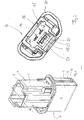
- FIG. 1 shows a view of a heater 1, which consists in principle of a heating section 2 and a plug part 4.
- the power supply lines for contacting the heater 1 are arranged in this plug part 4.
- the heating section 2 is inserted into a receptacle or pocket of a component to be heated, for example an SCR tank, the heating section 2 lying flat against the wall of this receptacle so that a good heat transfer is ensured.
- a non-electrically insulating insulating film 6 which optimizes the heat transfer is provided in the abutment region on the receptacle, not shown, on the heating section 2, which will be described in more detail later.
- a plug contour is attached, to which a correspondingly profiled plug connection of the power supply is applied, this plug contour 8 being designed so that a correct position mounting is ensured.
- FIG. 2 shows a plan view of the plug part 4 FIG. 1 , It can be seen a plug flange 10, in accordance with the view FIG. 2 covers the heating section 2 and also acts as insertion limit for this.
- the profiled plug part 4 engages with a peripheral wall a plug space 12, in which the above-mentioned plug of the power supply is at least partially immersed.
- a plug space 12 At the bottom of this plug space 12 can be seen two projecting into this tongue-shaped power supply lines 14, 16 of the heating section 2 and also in this plug space 12 hineing protruding actuating projection 18 of an activation pin 20.
- This actuating projection 18 is supported on two spring tongues 22, 24 of the plug part 4 and extends through the bottom of the plug space 12 into the heating section 2.
- the spring tongues 22, 24 each have a locking projection which dips into recesses 26, 78 of the activation pin 20. In the release position of the activation pins 20, the spring tongues 22, 24 engage in the recess 78 of the activation pin 20, this is thus fixed in position against accidental displacement. If one acts on the actuating projection 18 in the illustration according to FIG. 2 From the viewer forth with a thrust, so the resilient engagement of the spring tongues 22, 24 is released, so that the activation pin 20 can be moved in the direction of the heating section 2. In the operative position, the Spring tongues 22, 24 then into the recess 26 of the activation pin and lock it. This feature is explained in detail below.
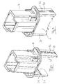
- FIG. 3 shows the heater 1 according to FIG. 1 With removed insulating film 6.
- FIG. 4 shows the plug part 4 alone without heating section 2. Accordingly, extending from the plug flange 10 down on both sides of the heating section ( Fig. 3 ) arranged holding legs 28, 30, which form practically end walls of the heating section 2. These holding legs 28, 30 are in turn designed with a profile 32, which allows a positional fixation in the recording of the component to be heated.
- the plug part 4 of the heater 1 is preferably made by injection molding of plastic.
- the latching lugs 33, 35 take the force (activating force) resulting from the insertion of the activation pin 20 onto the heating insert FIGS. 5 and 6 on.
- FIG. 5 shows a representation of the heater 1 with removed connector part 4. It can be clearly seen the U-shaped insulating film 6, the open side areas by the above, in FIG. 5 not visible retaining legs 28, 30 are covered. In this illustration, one recognizes the two power supply lines 14, 16 and the activation pin 20 with its actuating projection 18. In this the above-described recess 26 is formed, in which the (non-visible) spring tongues 22, 24 resiliently engage, said resilient engagement relatively easily can be canceled.
- the heating section 2 of the heater 1 is formed in this case with four PTC heating elements 34a, 34b and 36a, 36b, in the view according to FIG. 6 are clearly visible that the heater 1 shown without plug part 4 in a view rotated by about 90 ° FIG. 5 shows. Accordingly, in each case two PTC heating elements 34a, 34b and 36a, 36b face each other in pairs, the large areas of these PTC resistance elements extending parallel to the large areas of the insulating film 6. The space between the PTC resistance elements 34a, 34b and 36a, 36b is immersed approximately U-shaped trained first contact element 38 of the power supply 16 a, whose structure is particularly good FIG. 6 and the individual presentation according to FIG. 8 is removable.
- this first contact element 38 has two electrode plates 40, 42, each of which bears against one of the PTC resistor element pairs 34a, 34b or 36a, 36b and whose base area approximately corresponds to that of the associated resistor element pair.
- the two electrode plates 40, 42 are each connected to the front side by a base part 44a, 44b.
- Each of these base parts 44a, 44b is designed with an indentation 46a, 46b, so that the two electrode plates 40, 42 are elastically and parallel movable by elastic deformation of the base parts 44a, 44b and the associated indentations 46a, 46b.
- FIG. 5 are on the side edges of the electrode plates 40, 42 locking recesses 47, 49 for locking with the locking lugs 33, 35 are formed. In addition to the latching of the recesses 47, 49 and the activation force is added.
- the contact tongue 48 is connected to the electrode plate 40 via an approximately U-shaped bent contact leg 50.
- a spring element 52, 54 (see FIGS. 6 and 7 ) held.
- two Crimplaschen 56a, 56b and 58a, 58b (see FIG. 8 ), each of which laterally surround an upper transverse strut 60, 62 of the respective spring element 52, 54.
- the two spring elements 48, 50 further have according to the individual representation in FIG. 9 and the FIGS. 6 and 7 lower transverse struts 64, 66 which extend parallel to the upper transverse struts 60, 62 and between which two mutually spaced spring bridges 68a, 68b and 70a, 70b arch each other.
- FIGS. 6 and 7 lower transverse struts 64, 66 which extend parallel to the upper transverse struts 60, 62 and between which two mutually spaced spring bridges 68a, 68b and 70a, 70b arch each other.
- each spring bridge 68a, 70a lying in the direction of viewing are visible, and the associated spring bridges 68b and 70b are in the view according to FIG FIG. 7 covered by the spring bridges 68a and 70a and in the view according to FIG. 6 not visible.
- At the lateral narrow edges of the upper transverse struts 60, 62 are each two recesses 61 a, 61 b formed in the mounted state of the Crimplaschen 56a, 56b; 58a, 58b are encompassed in order to connect the spring elements 52, 54 with the corresponding power supply lines 14, 16 mechanically.
- Each spring element 52, 54 is thus supported with its upper and lower transverse struts 60, 64 and 62, 66 on the associated electrode plate 40, 42, wherein a lateral position fixing on the formed on each electrode plate 40, 42 Crimplaschen 56 a, 56 b and 58a, 58b takes place.
- the two vertices 72, 74 ( FIG. 7 ) of the spring bridges 68, 70 are at a comparatively small distance from one another.
- an activation section 76 of the activation pin 20 dips into the area between the opposing spring bridges 68, 70 and is in the mounting position or release position (see FIG. 7 ) but not in touching contact with the spring elements 52, 54.
- this has an approximately fork-shaped structure, wherein the actuating projection 18 with the recess 26 and a further opening 78 upwards (view FIG. 10 ) protrudes from a slightly raised to the level of the activation section 76 connection 80 from which two legs 82, 84 extend, which together form the activation section 76.
- These legs have a folded end portion 86, 88, which is bent back by a bending operation on the plane of the attachment-side part of the legs 82, 84, in which case the end-side end face regions 90, 92 are again slightly bent out of this plane.
- the activation pin 20 is displaceable via suitable guides in the plug part 4 (vertically in FIG. 6 ) guided.
- FIG. 11 shows a single representation of the second power supply 14, which has a similar structure as that based FIG. 8 explained power supply 16 has and according to the representations in the FIGS. 5 and 6 is nested with this.
- the power supply 14 has two electrode plates 94, 96 with approximately the same base area as the electrode plates 40, 42. Both electrode plates 94, 96 are in turn connected to one another via frontally connected base parts 98a, 98b, each with a concavity 100a, 100b.
- a contact tongue 102 is connected to the electrode plate 94 via a U-part 104.
- Both power supply lines 14, 16 are formed as stamped and bent parts.
- FIG. 11 is formed on the electrode plate 96, a fixing element 110, the more clearly in the figure FIG. 5 is visible. During assembly, this fixing element 110 engages in a corresponding recess of the plug part 4 in order to fix the heating section 2.
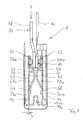
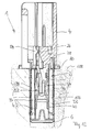
- FIG. 12 shows a heater 1 used in a receptacle or pocket of a container to be heated, wherein the heating section 2 is received flush in the pocket 106 and the plug member 4 is seated with the plug flange 10 on an outer surface 108.
- the insulating sheet 6 sits flat against the peripheral walls of the pocket 106, wherein, however, the end face of the heating section 2 may be spaced to a bottom of the bag.
- the activation pin 20 in its in FIG. 7 leave shown position in which the electrode plates 40, 42 and 94, 96 are not contacted with the PTC resistor elements 34, 36 with bias.
- the insulating film 6 is not pressed against the wall of the pocket 106.
- the gap s between the inner electrode plates 40, 42 and the respectively associated PTC resistor elements 34a, 34b; 36a, 36b available.
- the activation pin 20 via the projecting into the plug space 12 actuating projection 18 from the illustration FIG. 6 moved down ( Fig.
- the insulating film 6 serves as electrical insulation.
- the insulating film can also be used as a compensation for slight bumps in the recording of the component.
- a particular advantage of this design is that any existing manufacturing tolerances and temperature-related dimensional variations can be compensated by the considerable spring force of the spring bridges 74a, 74b, so that a sufficient mechanical, thermal and electrical contact is always ensured.
- the assembly of the heater 1 itself and its insertion into the receptacle is facilitated by the game s.
- this concept can be further simplified if the actuating projection 18 of the activation pin 20 acts as a power supply, so that then the energization is only possible when adjusting the activation pin 20 in its activation position.
- the construction principle underlying the invention can be easily adapted to different sizes and benefits.
- an electrical heater with at least one heating element, which can be brought into thermal contact with a wall of a component to be heated.
- This heating section is provided with an activation pin, which is adjustable from a release position to an activation position to adjust the heating element after insertion into the receptacle in an operative position in which a sufficient thermal and / or electrical contact is ensured.
Abstract
Description
Die Erfindung betrifft einen elektrischen Heizer gemäß dem Oberbegriff des Patentanspruchs 1.The invention relates to an electric heater according to the preamble of
Derartige elektrische Heizer können beispielsweise im Blow-By-System von Verbrennungsmotoren oder zum Aufheizen eines Tanks eines SCR-Systems (Selektive Katalytische Reduktion) verwendet werden. Auf der Homepage der Anmelderin (www.dbk-group.de) sind Beispiele derartiger elektrischer Heizungen dargestellt. Demgemäß haben diese einen Heizabschnitt, der in eine entsprechend gestaltete Aufnahme des zu thermostatisierenden Bauteils, beispielsweise einen Tank oder einen Strömungspfad des Blow-By-Gases eingesetzt wird. Dieser Heizabschnitt geht in einen Stecker- oder Kontaktierungsteil über, in dem die Stromzuführungen für den Heizer angeordnet sind. Bei den bekannten Heizern werden Widerstandselemente, beispielsweise PTC-Heizelemente verwendet, die über die Stromzuführungen des Kontaktierungsteils bestromt sind und möglichst flächig an einem Wandungsbereich des Gehäuseabschnitts anliegen, so dass die Wärme direkt über die Wandung des Heizabschnitts und die benachbarte Wandung des zu thermostatisierenden Bauteils übertragen wird. Dabei ist es wichtig, dass zur Verbesserung der Wärmeübertragung zum Einen eine große Wärmeaustauschfläche vorhanden ist und des Weiteren keine isolierenden Luftspalte im Wärmeübertragungspfad angeordnet sind.Such electric heaters can be used, for example, in the blow-by system of internal combustion engines or for heating a tank of an SCR system (Selective Catalytic Reduction). On the homepage of the applicant ( www.dbk-group.de ) examples of such electrical heaters are shown. Accordingly, these have a heating section which is inserted into a correspondingly shaped receptacle of the component to be thermostated, for example a tank or a flow path of the blow-by gas. This heating section goes into a plug or contacting part, in which the power supply lines for the heater are arranged. In the known heaters, resistance elements, for example PTC heating elements are used, which are energized via the power supply lines of the contacting and as possible abut against a wall portion of the housing portion, so that the heat transmitted directly through the wall of the heating section and the adjacent wall of the component to be thermostated becomes. It is important that on the one hand to improve the heat transfer, a large heat exchange surface is present and further no insulating air gaps are arranged in the heat transfer path.
Problematisch ist dabei, dass es aufgrund von Toleranzen bei der Herstellung und Temperaturschwankungen im Betrieb des Heizers bzw. des zu beheizenden Bauteils im Bereich der Anlage des Heizelementes an die Wandung zu einem isolierenden Luftspalt kommen kann. Diesen Nachteil kann man nur dann ausschließen, wenn die Passungen für die die Heizelemente abstützenden Bereiche sehr eng gewählt sind, dann ist allerdings die Montage des Heizers aufgrund der erforderlichen engen Passmaße relativ schwierig, so dass insbesondere bei der Verwendung von PTC-Bausteinen die Gefahr einer Beschädigung des Heizelementes besteht.The problem is that it may come to an insulating air gap in the area of the system of the heating element to the wall due to tolerances in the production and temperature fluctuations in the operation of the heater or the component to be heated. This disadvantage can only be ruled out if the fits for the heating elements supporting areas are very narrow, but then the installation of the heater due to the required tight fitting dimensions is relatively difficult, so that especially in the use of PTC devices the risk of Damage to the heating element is.
In der
Dem gegenüber liegt der Erfindung die Aufgabe zugrunde, einen elektrischen Heizer zu schaffen, bei dem eine optimale Wärmeübertragung bei einfacher Montage gewährleistet ist.In contrast, the invention has for its object to provide an electric heater, in which an optimal heat transfer is ensured with simple installation.
Diese Aufgabe wird durch einen elektrischen Heizer mit den Merkmalen des Patentanspruchs 1 gelöst.This object is achieved by an electric heater with the features of
Vorteilhafte Weiterbildungen der Erfindung sind Gegenstand der Unteransprüche.Advantageous developments of the invention are the subject of the dependent claims.
Der erfindungsgemäße elektrische Heizer hat einen Heizabschnitt, der in eine Aufnahme eines zu thermostatisierenden Bauteils einsetzbar ist. Der Heizer hat des Weiteren über Stromzuführungen bestromte Heizelemente. Erfindungsgemäß ist der Heizer mit einem Aktivierungspin ausgeführt, der aus einer Freigabeposition in eine Aktivierungspostion verstellbar ist. In der Freigabeposition befindet sich das Heizelement in einer spielbehafteten Montageposition, in der das Heizelement nicht oder nur unwesentlich in thermischen Kontakt mit der Wandung oder in elektrischem Kontakt mit den Stromzuführungen steht. Durch Verschieben des Aktivierungspins in die Aktivierungsposition wird das Heizelement oder die Stromzuführung in eine Wirkposition verstellt, in der der thermische und/oder elektrische Kontakt im Wesentlichen spielfrei und flächig ausgebildet ist.The electric heater according to the invention has a heating section which can be inserted into a receptacle of a component to be thermostated. The heater also has heating elements powered by power supply. According to the invention, the heater is designed with an activation pin, which is adjustable from a release position into an activation position. In the release position, the heating element is in a play-loaded mounting position in which the heating element is not or only slightly in thermal contact with the wall or in electrical contact with the power supply lines. By moving the activation pin in the activation position, the heating element or the power supply is adjusted to an operative position in which the thermal and / or electrical contact is formed substantially free of play and area.
Mit der erfindungsgemäßen Lösung wird somit ein Heizer geschaffen, bei dem die Heizelemente zunächst in einer spielbehafteten, nicht in kompakter Anlage an der zu beheizenden Wandung oder den Stromzuführungen angeordnet sind. Zur Aktivierung des Heizers wird dann der Aktivierungspin verstellt, so dass die Heizelemente in ihre Wirkposition verstellt oder verschoben werden. Auf diese Weise ist die Montage des Heizers wesentlich vereinfacht, da die Heizelemente zunächst mit vergleichsweise großem Spiel im Gehäuse aufgenommen sind. In der Aktivierungsposition des Aktivierungspins wird dieses Spiel dann aufgehoben, so dass der gewünschte thermische und elektrische Kontakt mit sehr gutem Wärmeübergang hergestellt ist.With the solution according to the invention thus a heater is provided in which the heating elements are initially arranged in a game-afflicted, not in a compact system on the wall to be heated or the power supply lines. To activate the heater then the activation pin is adjusted, so that the heating elements are adjusted or moved into their operative position. In this way, the assembly of the Heater much easier, since the heating elements are initially taken up with relatively large game in the housing. In the activation position of the activation pin this game is then canceled, so that the desired thermal and electrical contact is made with very good heat transfer.
Mit der aufgrund der Verschiebung des Aktivierungspins hergestellten thermischen und/oder elektrischen Kontaktierung geht vorzugsweise auch eine mechanische Kontaktierung einher, die dafür sorgt, dass die Heizelemente gegen die entsprechende Wandung der Aufnahme des Bauteils gepresst werden. Die Anmelderin behält sich vor, diese mechanische Kontaktierung zusätzlich oder unabhängig von der thermischen und elektrischen Kontaktierung zu beanspruchen. Dabei kann die mechanische Kontaktierung der Heizelemente mittelbar, d.h. über zwischengeschaltete Bauelemente oder unmittelbar erfolgen.The thermal and / or electrical contacting produced by virtue of the displacement of the activation pin is preferably accompanied by mechanical contacting, which ensures that the heating elements are pressed against the corresponding wall of the receptacle of the component. The Applicant reserves the right to claim this mechanical contact additionally or independently of the thermal and electrical contact. In this case, the mechanical contacting of the heating elements indirectly, i. via intermediate components or directly.
Bei einem bevorzugten Ausführungsbeispiel der Erfindung hat der Aktivierungspin einen aus einem Gehäuseabschnitt auskragenden Betätigungsvorsprung und einen heizelementseitigen Aktivierungsabschnitt, der zum Aktivieren des Heizers durch Verstellen des Betätigungsvorsprungs in Wirkverbindung mit dem Heizelement gelangt, wobei der Aktivierungspin mittelbar oder unmittelbar am Heizelement anliegen kann.In a preferred embodiment of the invention, the activation pin has an actuating projection projecting from a housing section and a heater-element-side activation section which comes into operative connection with the heating element for activating the heater by adjusting the actuating projection, wherein the activation pin can abut directly or indirectly on the heating element.
Vorteilhaft ist auch, dass bei in Freigabeposition des Aktivierungspins ein elektrischer Gegenstecker nicht steckbar ist. Somit wird eine einfache Absicherung gegen Fehlnutzung realisiert.It is also advantageous that in the release position of the activation pin, an electrical mating connector is not pluggable. Thus, a simple hedge against misuse is realized.
Der Aufbau des Heizers ist besonders einfach, wenn zumindest eine der Stromzuführungen mit einem Federelement ausgebildet ist, das in der Wirkposition des Aktivierungspins das Heizelement in Richtung der Wandung beaufschlagt.The structure of the heater is particularly simple if at least one of the power supply lines is formed with a spring element which, in the active position of the activation pin, acts on the heating element in the direction of the wall.
Bei einer Variante der Erfindung ist ein Federelement an einer Stromzuführung befestigt. Dieses kann beispielsweise über Crimplaschen der Stromzuführung gehalten werden.In a variant of the invention, a spring element is attached to a power supply. This can be maintained, for example, via Crimplaschen the power supply.
Bei einem Ausführungsbeispiel der Erfindung ist zumindest eine der Stromzuführungen federnd ausgebildet, so dass durch die Federwirkung Toleranzabweichungen ausgeglichen werden können und eine flächige Anlage des Heizelements in seiner Wirkposition gewährleistet ist.In one embodiment of the invention, at least one of the power supply lines is resilient, so that by the spring action tolerance deviations can be compensated and a flat contact of the heating element is ensured in its operative position.
Die Stromzuführung kann einen etwa U-förmigen Aufbau haben, wobei an einer U-Basis eine die Federwirkung bereitstellende Einwölbung ausgebildet ist.The power supply can have an approximately U-shaped construction, wherein on a U-base, a spring effect providing concavity is formed.
Erfindungsgemäß wird es bevorzugt, wenn beide Stromzuführungen federnd und/oder mit Federelementen ausgebildet sind, über die beispielsweise jeweils zumindest ein Heizelement in Richtung seiner Wirkposition beaufschlagbar ist.According to the invention it is preferred if both power supply lines are resilient and / or formed with spring elements, via which, for example, at least one heating element in the direction of its operative position can be acted upon.
Bei einem Ausführungsbeispiel der Erfindung hat der Heizer zumindest zwei einander gegenüberliegende Heizelemente, denen jeweils ein Federelement im Sinne der vorstehenden Ausführungen zugeordnet ist, wobei der Aktivierungspin in seiner Aktivierungsposition zwischen die beiden Federelemente eintaucht, um die Heizelemente durch die Federkraft in Richtung der Wandung zu beaufschlagen. Bei dieser Variante werden somit zwei Heizelemente an einander gegenüberliegende Wandungen der Aufnahme des aufzuheizenden Bauteils gepresst, sodass aufgrund der verbesserten Wärmeübertragungsfläche gegenüber dem in der Beschreibungseinleitung zitierten Stand der Technik ein erheblich verbesserter Wärmeeintrag mit hoher Leistungsdichte realisierbar ist.In one embodiment of the invention, the heater has at least two opposing heating elements, each associated with a spring element in the sense of the foregoing, wherein the activation pin dips in its activation position between the two spring elements to bias the heating elements by the spring force in the direction of the wall , In this variant, two heating elements are thus pressed against mutually opposite walls of the receptacle of the component to be heated, so that a significantly improved heat input with high power density can be realized due to the improved heat transfer surface compared to the cited in the introduction of the prior art.
Eine Variante der Erfindung sieht vor, dass insgesamt vier Heizelemente vorgesehen sind, die einander paarweise gegenüberliegen und zwischen denen Federelemente und ein Aktivierungspin angeordnet ist.A variant of the invention provides that a total of four heating elements are provided which face each other in pairs and between which spring elements and an activation pin is arranged.
Der Aktivierungspin kann aus Metall als Stanzbiegeteil mit einem umgefalzten Aktivierungsabschnitt oder aus Kunststoff ausgeführt sein.The activation pin can be made of metal as a stamped and bent part with a folded activation section or made of plastic.
Bei einer Weiterbildung der Erfindung wird der Aktivierungspin in seiner Aktivierungsposition durch kraft- oder formschlüssigen Eingriff mit einem weiteren Bauelement des Heizers, beispielsweise dem vorgenannten Steckerteil lagefixiert. Diese Lagefixierung kann beispielsweise durch eine Verrastung erfolgen, bei der eine Zunge in eine Ausnehmung des Aktivierungspins oder in kinematischer Umkehr ein Vorsprung des Aktivierungspins in eine Ausnehmung des Steckerteils oder eines sonstigen gehäusefesten Abschnitts des Heizers einschnappt.In a further development of the invention, the activation pin is fixed in position in its activation position by frictional or positive engagement with a further component of the heater, for example, the aforementioned plug part. This fixation can be done, for example, by latching, in which a tongue snaps into a recess of the activation pin or in kinematic reversal, a projection of the activation pins in a recess of the plug part or other housing-fixed portion of the heater.
Erfindungsgemäß wird es bevorzugt, wenn der elektrische Heizer mit PTC-Widerstandselementen ausgeführt ist.According to the invention it is preferred if the electrical heater is designed with PTC resistor elements.
Vorteilhaft ist an der beschriebenen Ausführung auch, dass der Heizer wieder demontierbar ist. Nach Deaktivierung des Aktivierungspins ist der Heizer wieder kraftlos entnehmbar und kann beispielsweise im Servicefall ersetzt werden. Hierbei ist jedoch darauf zu achten, dass der Heizer nicht willkürlich entfernt wird. Sinnvoll ist hier die Verwendung eines Spezialwerkzeugs.An advantage of the described embodiment also that the heater is removable again. After deactivation of the activation pin, the heater is again powerless removable and can be replaced, for example, in case of service. However, it is important to ensure that the heater is not removed arbitrarily. It makes sense to use a special tool here.
Ein bevorzugtes Ausführungsbeispiel der Erfindung wird im Folgenden anhand schematischer Zeichnungen näher erläutert. Es zeigen:
-
Figur 1 -
Figur 2Figur 1 -
Figur 3 den Heizer ausFigur 1 -
Figur 4Figur 1 -
Figur 5 eine dreidimensionale Ansicht des Heizers gemäßFigur 1 -
Figur 6Figur 5 in einer anderen Ansicht; -
Figur 7Figur 1 -
Figur 8 eine Einzeldarstellung einer ersten Stromzuführung des Heizers gemäßFigur 1 -
Figur 9 eine Einzeldarstellung eines Federelementes des Heizers ausFigur 1 -
Figur 10Figur 1 -
Figur 11 eine Einzeldarstellung einer zweiten Stromzuführung des Heizers ausFigur 1 -
Figur 12 den Heizer ausFigur 1
-
FIG. 1 a three-dimensional view of an electric heater according to the invention; -
FIG. 2 a view from the top on a heater according toFIG. 1 ; -
FIG. 3 the heater offFIG. 1 without insulating film; -
FIG. 4 a plug part of the heater offFIG. 1 ; -
FIG. 5 a three-dimensional view of the heater according toFIG. 1 without housing; -
FIG. 6 the arrangement according toFIG. 5 in another view; -
FIG. 7 a side view of the heater offFIG. 1 without housing; -
FIG. 8 a detailed representation of a first power supply of the heater according toFIG. 1 ; -
FIG. 9 an individual representation of a spring element of the heater offFIG. 1 ; -
FIG. 10 a single representation of an activation pin of the heater offFIG. 1 ; -
FIG. 11 a single representation of a second power supply of the heater offFIG. 1 and -
FIG. 12 the heater offFIG. 1 inserted in a bag.
Der Heizabschnitt 2 des Heizers 1 ist im vorliegenden Fall mit vier PTC-Heizelementen 34a, 34b und 36a, 36b ausgebildet, die in der Ansicht gemäß
Gemäß den Darstellungen in den
An den beiden Elektrodenplatten 40, 42 der Stromzuführung 16 ist jeweils ein Federelement 52, 54 (siehe
Jedes Federelement 52, 54 stützt sich somit mit seinen oberen und unteren Querstreben 60, 64 bzw. 62, 66 an der zugehörigen Elektrodenplatte 40, 42 ab, wobei eine seitliche Lagefixierung über die an jeder Elektrodenplatte 40, 42 ausgebildeten Crimplaschen 56a, 56b bzw. 58a, 58b erfolgt. Die beiden Scheitel 72, 74 (
Beim Einschieben des Aktivierungspins 20 zwischen die Federelemente 52, 54 bleiben die Querstreben 60, 62 durch ihre mittels der Crimplaschen 56a, 56b; 58a, 58b hergestellte Verbindung zu den Elektrodenplatten 40, 42 lagefixiert. Die Querstreben 64, 66 an den Federelemente 52, 54 werden beim Einschieben des Aktivierungspins 20 verschoben, behalten ihre Lage also nicht bei.When inserting the
Gemäß der Einzeldarstellung des Aktivierungspins 20 in
Wie erläutert, ist im Montagezustand der Spalt s zwischen den innen liegenden Elektrodenplatten 40, 42 und den jeweils zugeordneten PTC-Widerstandselementen 34a, 34b; 36a, 36b vorhanden. Nach dem durch das vorgegebene Spiel s nahezu kraftlosen Einsetzen des Heizers 1 in die Aufnahme 106 wird entweder durch den angesetzten Stecker oder aber durch ein geeignetes Werkzeug der Aktivierungspin 20 über den in den Steckerraum 12 hineinragenden Betätigungsvorsprung 18 aus der Darstellung gemäß
In der Darstellung gemäß
Ist die Aufnahme des Bauteils aus metallischem Werkstoff ausgeführt, dient die Isolierfolie 6 als elektrische Isolierung. Daneben kann die Isolierfolie auch als Ausgleich leichter Unebenheiten in der Aufnahme des Bauteils dienen.If the recording of the component made of metallic material, the insulating
Ein besonderer Vorteil dieser Konstruktion liegt darin, dass eventuell vorhandene Fertigungstoleranzen und temperaturbedingte Maßschwankungen durch die erhebliche Federkraft der Federbrücken 74a, 74b ausgeglichen werden können, so dass stets ein hinreichender mechanischer, thermischer und elektrischer Kontakt gewährleistet ist. Darüber hinaus wird die Montage des Heizers 1 selbst und dessen Einsetzen in die Aufnahme durch das Spiel s erleichtert.A particular advantage of this design is that any existing manufacturing tolerances and temperature-related dimensional variations can be compensated by the considerable spring force of the spring bridges 74a, 74b, so that a sufficient mechanical, thermal and electrical contact is always ensured. In addition, the assembly of the
Prinzipiell lässt sich dieses Konzept noch weiter vereinfachen, wenn der Betätigungsvorsprung 18 des Aktivierungspins 20 als Stromzuführung wirkt, so dass dann die Bestromung nur bei Verstellen des Aktivierungspins 20 in seine Aktivierungsposition möglich ist.In principle, this concept can be further simplified if the
Das der Erfindung zugrunde liegende Bauprinzip kann leicht auf verschiedene Größen und Leistungen angepasst werden.The construction principle underlying the invention can be easily adapted to different sizes and benefits.
Offenbart ist ein elektrischer Heizer mit zumindest einem Heizelement, das in thermischen Kontakt mit einer Wandung eines aufzuheizenden Bauteils bringbar ist. Dieser Heizabschnitt ist mit einem Aktivierungspin versehen, der aus einer Freigabeposition in eine Aktivierungsposition verstellbar ist, um das Heizelement nach Einsetzen in die Aufnahme in eine Wirkposition zu verstellen, in der ein hinreichender thermischer und/oder elektrischer Kontakt gewährleistet ist.Disclosed is an electrical heater with at least one heating element, which can be brought into thermal contact with a wall of a component to be heated. This heating section is provided with an activation pin, which is adjustable from a release position to an activation position to adjust the heating element after insertion into the receptacle in an operative position in which a sufficient thermal and / or electrical contact is ensured.
- 11
- Heizerstoker
- 22
- Heizabschnittheating section
- 44
- Steckerteilplug part
- 66
- Isolierfolieinsulation
- 88th
- Steckerkonturplug contour
- 1010
- Steckerflanschconnector flange
- 1212
- Steckerraumplug compartment
- 1414
- Stromzuführungpower supply
- 1616
- Stromzuführungpower supply
- 1818
- Betätigungsvorsprungoperating projection
- 2020
- Aktivierungspinenable pin
- 2222
- Federzungespring tongue
- 2424
- Federzungespring tongue
- 2626
- Ausnehmungrecess
- 2828
- Halteschenkelholding leg
- 3030
- Halteschenkelholding leg
- 3232
- Profilprofile
- 3333
- Rastnaselocking lug
- 3434
- PTC-WiderstandselementPTC resistive element
- 3535
- Rastnaselocking lug
- 3636
- PTC-WiderstandselementPTC resistive element
- 3838
- Kontaktelementcontact element
- 4040
- Elektrodenplatteelectrode plate
- 4242
- Elektrodenplatteelectrode plate
- 4444
- Basisteilbase
- 4646
- Einwölbungconcavity
- 4747
- Rastausnehmungrecess
- 4848
- Kontaktzungecontact tongue
- 4949
- Rastausnehmungrecess
- 5050
- Kontaktschenkelcontact legs
- 5252
- Federelementspring element
- 5454
- Federelementspring element
- 5656
- CrimplascheCrimplasche
- 5858
- CrimplascheCrimplasche
- 6060
- obere Querstrebeupper cross strut
- 6161
- Aussparungrecess
- 6262
- obere Querstrebeupper cross strut
- 6464
- untere Querstrebelower crossbar
- 6666
- untere Querstrebelower crossbar
- 6868
- Federbrückespring bridge
- 7070
- Federbrückespring bridge
- 7272
- Scheitelvertex
- 7474
- Scheitelvertex
- 7676
- Aktivierungsabschnittactivating section
- 7878
- Durchbruchbreakthrough
- 8080
- Anbindungconnection
- 8282
- Schenkelleg
- 8484
- Schenkelleg
- 8686
- umgefalzter Endabschnittfolded end section
- 8888
- umgefalzter Endabschnittfolded end section
- 9090
- StirnflächenbereichEnd face region
- 9292
- StirnflächenbereichEnd face region
- 9494
- Elektrodenplatteelectrode plate
- 9696
- Elektrodenplatteelectrode plate
- 9898
- Basisteilbase
- 100100
- Einwölbungconcavity
- 102102
- Kontaktzungecontact tongue
- 104104
- U-TeilU-part
- 106106
- Taschebag
- 108108
- Flächearea
- 110110
- Fixierelementfixing
Claims (15)
Priority Applications (1)
| Application Number | Priority Date | Filing Date | Title |
|---|---|---|---|
| EP16165765.5A EP3073800B1 (en) | 2010-09-10 | 2011-09-12 | Electric heater |
Applications Claiming Priority (1)
| Application Number | Priority Date | Filing Date | Title |
|---|---|---|---|
| DE102010037479.2A DE102010037479B4 (en) | 2010-09-10 | 2010-09-10 | Electric heater |
Related Child Applications (1)
| Application Number | Title | Priority Date | Filing Date |
|---|---|---|---|
| EP16165765.5A Division EP3073800B1 (en) | 2010-09-10 | 2011-09-12 | Electric heater |
Publications (2)
| Publication Number | Publication Date |
|---|---|
| EP2429257A1 true EP2429257A1 (en) | 2012-03-14 |
| EP2429257B1 EP2429257B1 (en) | 2016-04-20 |
Family
ID=44677701
Family Applications (2)
| Application Number | Title | Priority Date | Filing Date |
|---|---|---|---|
| EP11180922.4A Active EP2429257B1 (en) | 2010-09-10 | 2011-09-12 | Electric heater |
| EP16165765.5A Active EP3073800B1 (en) | 2010-09-10 | 2011-09-12 | Electric heater |
Family Applications After (1)
| Application Number | Title | Priority Date | Filing Date |
|---|---|---|---|
| EP16165765.5A Active EP3073800B1 (en) | 2010-09-10 | 2011-09-12 | Electric heater |
Country Status (4)
| Country | Link |
|---|---|
| EP (2) | EP2429257B1 (en) |
| DE (1) | DE102010037479B4 (en) |
| DK (1) | DK2429257T3 (en) |
| ES (1) | ES2575134T3 (en) |
Cited By (4)
| Publication number | Priority date | Publication date | Assignee | Title |
|---|---|---|---|---|
| WO2014077868A1 (en) * | 2012-11-19 | 2014-05-22 | Intelligent Energy, Inc. | Heater assembly, hydrogen generator and method of providing hydrogen gas |
| US10093538B2 (en) | 2012-11-19 | 2018-10-09 | Intelligent Energy Inc. | Heater assembly, hydrogen generator and method of providing hydrogen gas |
| WO2019072800A1 (en) * | 2017-10-10 | 2019-04-18 | Eichenauer Heizelemente Gmbh & Co. Kg | Tank heater |
| CN110145808A (en) * | 2019-06-24 | 2019-08-20 | 宁波奥克斯电气股份有限公司 | A kind of foldable air-conditioning auxiliary electrical heater device and air-conditioning |
Citations (8)
| Publication number | Priority date | Publication date | Assignee | Title |
|---|---|---|---|---|
| US3940591A (en) * | 1974-07-01 | 1976-02-24 | Texas Instruments Incorporated | Self-regulating electric heater |
| US4395623A (en) * | 1980-03-04 | 1983-07-26 | Murata Manufacturing Co., Ltd. | Self-regulating electric heater |
| US5194717A (en) * | 1990-10-18 | 1993-03-16 | Tecumseh Products Company | Bracket for mounting a crankcase heater |
| US5262619A (en) * | 1991-08-12 | 1993-11-16 | Siemens Matsushita Components Gmbh & Co. Kg | Heating device with PTC resistors non-abrasively positioned in a metallic heat body for heating flowing media |
| US20020040899A1 (en) * | 2000-10-11 | 2002-04-11 | Chang Kee Hung Daniel | Heat sink for a PTC heating element and a PTC heating member made thereof |
| EP1375997A1 (en) | 2002-06-27 | 2004-01-02 | David & Baader DBK Spezialfabrik elektrischer Apparate und Heizwiderstände GmbH | Heating device for a pipe and method of production |
| US20080117018A1 (en) * | 2006-11-16 | 2008-05-22 | Saleh Saleh A | Retainer system |
| EP2063683A1 (en) * | 2006-09-13 | 2009-05-27 | Calsonic Kansei Corporation | Electric heater and its manufacturing method |
Family Cites Families (2)
| Publication number | Priority date | Publication date | Assignee | Title |
|---|---|---|---|---|
| DE10325965B4 (en) | 2003-06-07 | 2007-01-11 | Mann + Hummel Gmbh | Heating device for fluids |
| US7537000B2 (en) | 2006-02-14 | 2009-05-26 | Honda Motor Co., Ltd | Engine with breather apparatus |
-
2010
- 2010-09-10 DE DE102010037479.2A patent/DE102010037479B4/en active Active
-
2011
- 2011-09-12 EP EP11180922.4A patent/EP2429257B1/en active Active
- 2011-09-12 ES ES11180922.4T patent/ES2575134T3/en active Active
- 2011-09-12 DK DK11180922.4T patent/DK2429257T3/en active
- 2011-09-12 EP EP16165765.5A patent/EP3073800B1/en active Active
Patent Citations (8)
| Publication number | Priority date | Publication date | Assignee | Title |
|---|---|---|---|---|
| US3940591A (en) * | 1974-07-01 | 1976-02-24 | Texas Instruments Incorporated | Self-regulating electric heater |
| US4395623A (en) * | 1980-03-04 | 1983-07-26 | Murata Manufacturing Co., Ltd. | Self-regulating electric heater |
| US5194717A (en) * | 1990-10-18 | 1993-03-16 | Tecumseh Products Company | Bracket for mounting a crankcase heater |
| US5262619A (en) * | 1991-08-12 | 1993-11-16 | Siemens Matsushita Components Gmbh & Co. Kg | Heating device with PTC resistors non-abrasively positioned in a metallic heat body for heating flowing media |
| US20020040899A1 (en) * | 2000-10-11 | 2002-04-11 | Chang Kee Hung Daniel | Heat sink for a PTC heating element and a PTC heating member made thereof |
| EP1375997A1 (en) | 2002-06-27 | 2004-01-02 | David & Baader DBK Spezialfabrik elektrischer Apparate und Heizwiderstände GmbH | Heating device for a pipe and method of production |
| EP2063683A1 (en) * | 2006-09-13 | 2009-05-27 | Calsonic Kansei Corporation | Electric heater and its manufacturing method |
| US20080117018A1 (en) * | 2006-11-16 | 2008-05-22 | Saleh Saleh A | Retainer system |
Cited By (5)
| Publication number | Priority date | Publication date | Assignee | Title |
|---|---|---|---|---|
| WO2014077868A1 (en) * | 2012-11-19 | 2014-05-22 | Intelligent Energy, Inc. | Heater assembly, hydrogen generator and method of providing hydrogen gas |
| US9944521B2 (en) | 2012-11-19 | 2018-04-17 | Intelligent Energy Inc. | Hydrogen generator having a thermal actuator |
| US10093538B2 (en) | 2012-11-19 | 2018-10-09 | Intelligent Energy Inc. | Heater assembly, hydrogen generator and method of providing hydrogen gas |
| WO2019072800A1 (en) * | 2017-10-10 | 2019-04-18 | Eichenauer Heizelemente Gmbh & Co. Kg | Tank heater |
| CN110145808A (en) * | 2019-06-24 | 2019-08-20 | 宁波奥克斯电气股份有限公司 | A kind of foldable air-conditioning auxiliary electrical heater device and air-conditioning |
Also Published As
| Publication number | Publication date |
|---|---|
| ES2575134T3 (en) | 2016-06-24 |
| DK2429257T3 (en) | 2016-08-01 |
| DE102010037479A1 (en) | 2012-03-15 |
| EP3073800B1 (en) | 2020-01-15 |
| EP3073800A1 (en) | 2016-09-28 |
| EP2429257B1 (en) | 2016-04-20 |
| DE102010037479B4 (en) | 2023-03-16 |
Similar Documents
| Publication | Publication Date | Title |
|---|---|---|
| EP1564503B1 (en) | Electical heating device of low height | |
| EP2866306B1 (en) | Contact socket for an electric plug | |
| EP2025541B1 (en) | Heating element of an electric heating device | |
| EP2298582B1 (en) | Electric heating device and method for its production | |
| DE102005033696B4 (en) | contact element | |
| EP2058904B1 (en) | Hermaphrodite plug-in connector | |
| EP2429257B1 (en) | Electric heater | |
| EP3293833A1 (en) | Current rail connector | |
| DE502005007754C5 (en) | Electric switch | |
| DE102014117062B4 (en) | Spring-loaded terminal | |
| DE102009036807B4 (en) | Electrical connector assembly with reduced insertion force | |
| EP2126327B1 (en) | Device for producing a temperature gradient | |
| DE102013101736A1 (en) | Arrangement for fastening and positioning of relays | |
| EP0860846B1 (en) | Electrical power regulator, in particular for electric heaters | |
| WO2018073346A1 (en) | Contact part | |
| BE1026101B1 (en) | Contact element with a contact body and a spring element arranged thereon | |
| EP0388598A1 (en) | One-piece connection casing | |
| EP2498577B1 (en) | Assembly for a hob and induction hob with such an assembly | |
| EP1088697A2 (en) | Electric plug-in connector | |
| DE19846577C2 (en) | Electrical device with a connection clip and a connection clip receptacle for connection to a second electrical device | |
| EP2650897A1 (en) | Temperature-sensitive electrical switch and method for producing the same | |
| DE19648277B4 (en) | Electrical connection terminal | |
| DE19706249B4 (en) | Electrical control device, in particular for electric heating apparatus and method for its production | |
| DE4134171C2 (en) | Electric cigar lighter with overheating protection | |
| WO2024037909A1 (en) | Connection terminal for connecting an electrical wire |
Legal Events
| Date | Code | Title | Description |
|---|---|---|---|
| AK | Designated contracting states |
Kind code of ref document: A1 Designated state(s): AL AT BE BG CH CY CZ DE DK EE ES FI FR GB GR HR HU IE IS IT LI LT LU LV MC MK MT NL NO PL PT RO RS SE SI SK SM TR |
|
| AX | Request for extension of the european patent |
Extension state: BA ME |
|
| PUAI | Public reference made under article 153(3) epc to a published international application that has entered the european phase |
Free format text: ORIGINAL CODE: 0009012 |
|
| RIN1 | Information on inventor provided before grant (corrected) |
Inventor name: LECOENT, PATRICK Inventor name: HEIDELBERGER, WALTER |
|
| 17P | Request for examination filed |
Effective date: 20120827 |
|
| RAP1 | Party data changed (applicant data changed or rights of an application transferred) |
Owner name: DBK DAVID + BAADER GMBH |
|
| 17Q | First examination report despatched |
Effective date: 20150223 |
|
| GRAP | Despatch of communication of intention to grant a patent |
Free format text: ORIGINAL CODE: EPIDOSNIGR1 |
|
| INTG | Intention to grant announced |
Effective date: 20151021 |
|
| GRAS | Grant fee paid |
Free format text: ORIGINAL CODE: EPIDOSNIGR3 |
|
| GRAA | (expected) grant |
Free format text: ORIGINAL CODE: 0009210 |
|
| AK | Designated contracting states |
Kind code of ref document: B1 Designated state(s): AL AT BE BG CH CY CZ DE DK EE ES FI FR GB GR HR HU IE IS IT LI LT LU LV MC MK MT NL NO PL PT RO RS SE SI SK SM TR |
|
| REG | Reference to a national code |
Ref country code: GB Ref legal event code: FG4D Free format text: NOT ENGLISH |
|
| REG | Reference to a national code |
Ref country code: CH Ref legal event code: EP |
|
| REG | Reference to a national code |
Ref country code: AT Ref legal event code: REF Ref document number: 793649 Country of ref document: AT Kind code of ref document: T Effective date: 20160515 |
|
| REG | Reference to a national code |
Ref country code: IE Ref legal event code: FG4D Free format text: LANGUAGE OF EP DOCUMENT: GERMAN |
|
| REG | Reference to a national code |
Ref country code: DE Ref legal event code: R096 Ref document number: 502011009502 Country of ref document: DE |
|
| REG | Reference to a national code |
Ref country code: SE Ref legal event code: TRGR |
|
| REG | Reference to a national code |
Ref country code: ES Ref legal event code: FG2A Ref document number: 2575134 Country of ref document: ES Kind code of ref document: T3 Effective date: 20160624 |
|
| REG | Reference to a national code |
Ref country code: DK Ref legal event code: T3 Effective date: 20160725 |
|
| REG | Reference to a national code |
Ref country code: NO Ref legal event code: T2 Effective date: 20160420 |
|
| REG | Reference to a national code |
Ref country code: LT Ref legal event code: MG4D |
|
| REG | Reference to a national code |
Ref country code: FR Ref legal event code: PLFP Year of fee payment: 6 |
|
| REG | Reference to a national code |
Ref country code: NL Ref legal event code: MP Effective date: 20160420 |
|
| PG25 | Lapsed in a contracting state [announced via postgrant information from national office to epo] |
Ref country code: PL Free format text: LAPSE BECAUSE OF FAILURE TO SUBMIT A TRANSLATION OF THE DESCRIPTION OR TO PAY THE FEE WITHIN THE PRESCRIBED TIME-LIMIT Effective date: 20160420 Ref country code: NL Free format text: LAPSE BECAUSE OF FAILURE TO SUBMIT A TRANSLATION OF THE DESCRIPTION OR TO PAY THE FEE WITHIN THE PRESCRIBED TIME-LIMIT Effective date: 20160420 Ref country code: LT Free format text: LAPSE BECAUSE OF FAILURE TO SUBMIT A TRANSLATION OF THE DESCRIPTION OR TO PAY THE FEE WITHIN THE PRESCRIBED TIME-LIMIT Effective date: 20160420 |
|
| PG25 | Lapsed in a contracting state [announced via postgrant information from national office to epo] |
Ref country code: PT Free format text: LAPSE BECAUSE OF FAILURE TO SUBMIT A TRANSLATION OF THE DESCRIPTION OR TO PAY THE FEE WITHIN THE PRESCRIBED TIME-LIMIT Effective date: 20160822 Ref country code: RS Free format text: LAPSE BECAUSE OF FAILURE TO SUBMIT A TRANSLATION OF THE DESCRIPTION OR TO PAY THE FEE WITHIN THE PRESCRIBED TIME-LIMIT Effective date: 20160420 Ref country code: HR Free format text: LAPSE BECAUSE OF FAILURE TO SUBMIT A TRANSLATION OF THE DESCRIPTION OR TO PAY THE FEE WITHIN THE PRESCRIBED TIME-LIMIT Effective date: 20160420 Ref country code: LV Free format text: LAPSE BECAUSE OF FAILURE TO SUBMIT A TRANSLATION OF THE DESCRIPTION OR TO PAY THE FEE WITHIN THE PRESCRIBED TIME-LIMIT Effective date: 20160420 Ref country code: GR Free format text: LAPSE BECAUSE OF FAILURE TO SUBMIT A TRANSLATION OF THE DESCRIPTION OR TO PAY THE FEE WITHIN THE PRESCRIBED TIME-LIMIT Effective date: 20160721 |
|
| REG | Reference to a national code |
Ref country code: DE Ref legal event code: R097 Ref document number: 502011009502 Country of ref document: DE |
|
| PG25 | Lapsed in a contracting state [announced via postgrant information from national office to epo] |
Ref country code: CZ Free format text: LAPSE BECAUSE OF FAILURE TO SUBMIT A TRANSLATION OF THE DESCRIPTION OR TO PAY THE FEE WITHIN THE PRESCRIBED TIME-LIMIT Effective date: 20160420 Ref country code: RO Free format text: LAPSE BECAUSE OF FAILURE TO SUBMIT A TRANSLATION OF THE DESCRIPTION OR TO PAY THE FEE WITHIN THE PRESCRIBED TIME-LIMIT Effective date: 20160420 Ref country code: SK Free format text: LAPSE BECAUSE OF FAILURE TO SUBMIT A TRANSLATION OF THE DESCRIPTION OR TO PAY THE FEE WITHIN THE PRESCRIBED TIME-LIMIT Effective date: 20160420 Ref country code: EE Free format text: LAPSE BECAUSE OF FAILURE TO SUBMIT A TRANSLATION OF THE DESCRIPTION OR TO PAY THE FEE WITHIN THE PRESCRIBED TIME-LIMIT Effective date: 20160420 |
|
| PLBE | No opposition filed within time limit |
Free format text: ORIGINAL CODE: 0009261 |
|
| STAA | Information on the status of an ep patent application or granted ep patent |
Free format text: STATUS: NO OPPOSITION FILED WITHIN TIME LIMIT |
|
| PG25 | Lapsed in a contracting state [announced via postgrant information from national office to epo] |
Ref country code: BE Free format text: LAPSE BECAUSE OF NON-PAYMENT OF DUE FEES Effective date: 20160930 Ref country code: SM Free format text: LAPSE BECAUSE OF FAILURE TO SUBMIT A TRANSLATION OF THE DESCRIPTION OR TO PAY THE FEE WITHIN THE PRESCRIBED TIME-LIMIT Effective date: 20160420 |
|
| 26N | No opposition filed |
Effective date: 20170123 |
|
| PG25 | Lapsed in a contracting state [announced via postgrant information from national office to epo] |
Ref country code: MC Free format text: LAPSE BECAUSE OF FAILURE TO SUBMIT A TRANSLATION OF THE DESCRIPTION OR TO PAY THE FEE WITHIN THE PRESCRIBED TIME-LIMIT Effective date: 20160420 |
|
| REG | Reference to a national code |
Ref country code: CH Ref legal event code: PL |
|
| PG25 | Lapsed in a contracting state [announced via postgrant information from national office to epo] |
Ref country code: SI Free format text: LAPSE BECAUSE OF FAILURE TO SUBMIT A TRANSLATION OF THE DESCRIPTION OR TO PAY THE FEE WITHIN THE PRESCRIBED TIME-LIMIT Effective date: 20160420 |
|
| REG | Reference to a national code |
Ref country code: IE Ref legal event code: MM4A |
|
| PG25 | Lapsed in a contracting state [announced via postgrant information from national office to epo] |
Ref country code: CH Free format text: LAPSE BECAUSE OF NON-PAYMENT OF DUE FEES Effective date: 20160930 Ref country code: IE Free format text: LAPSE BECAUSE OF NON-PAYMENT OF DUE FEES Effective date: 20160912 Ref country code: LI Free format text: LAPSE BECAUSE OF NON-PAYMENT OF DUE FEES Effective date: 20160930 |
|
| PG25 | Lapsed in a contracting state [announced via postgrant information from national office to epo] |
Ref country code: LU Free format text: LAPSE BECAUSE OF NON-PAYMENT OF DUE FEES Effective date: 20160912 |
|
| REG | Reference to a national code |
Ref country code: FR Ref legal event code: PLFP Year of fee payment: 7 |
|
| PGFP | Annual fee paid to national office [announced via postgrant information from national office to epo] |
Ref country code: NO Payment date: 20170921 Year of fee payment: 7 Ref country code: FI Payment date: 20170920 Year of fee payment: 7 Ref country code: IT Payment date: 20170926 Year of fee payment: 7 |
|
| REG | Reference to a national code |
Ref country code: AT Ref legal event code: MM01 Ref document number: 793649 Country of ref document: AT Kind code of ref document: T Effective date: 20160912 |
|
| REG | Reference to a national code |
Ref country code: BE Ref legal event code: MM Effective date: 20160930 |
|
| PGFP | Annual fee paid to national office [announced via postgrant information from national office to epo] |
Ref country code: DK Payment date: 20170925 Year of fee payment: 7 |
|
| PG25 | Lapsed in a contracting state [announced via postgrant information from national office to epo] |
Ref country code: AT Free format text: LAPSE BECAUSE OF NON-PAYMENT OF DUE FEES Effective date: 20160912 |
|
| PG25 | Lapsed in a contracting state [announced via postgrant information from national office to epo] |
Ref country code: HU Free format text: LAPSE BECAUSE OF FAILURE TO SUBMIT A TRANSLATION OF THE DESCRIPTION OR TO PAY THE FEE WITHIN THE PRESCRIBED TIME-LIMIT; INVALID AB INITIO Effective date: 20110912 Ref country code: CY Free format text: LAPSE BECAUSE OF FAILURE TO SUBMIT A TRANSLATION OF THE DESCRIPTION OR TO PAY THE FEE WITHIN THE PRESCRIBED TIME-LIMIT Effective date: 20160420 |
|
| PG25 | Lapsed in a contracting state [announced via postgrant information from national office to epo] |
Ref country code: IS Free format text: LAPSE BECAUSE OF FAILURE TO SUBMIT A TRANSLATION OF THE DESCRIPTION OR TO PAY THE FEE WITHIN THE PRESCRIBED TIME-LIMIT Effective date: 20160420 Ref country code: TR Free format text: LAPSE BECAUSE OF FAILURE TO SUBMIT A TRANSLATION OF THE DESCRIPTION OR TO PAY THE FEE WITHIN THE PRESCRIBED TIME-LIMIT Effective date: 20160420 Ref country code: MK Free format text: LAPSE BECAUSE OF FAILURE TO SUBMIT A TRANSLATION OF THE DESCRIPTION OR TO PAY THE FEE WITHIN THE PRESCRIBED TIME-LIMIT Effective date: 20160420 Ref country code: MT Free format text: LAPSE BECAUSE OF FAILURE TO SUBMIT A TRANSLATION OF THE DESCRIPTION OR TO PAY THE FEE WITHIN THE PRESCRIBED TIME-LIMIT Effective date: 20160420 |
|
| PG25 | Lapsed in a contracting state [announced via postgrant information from national office to epo] |
Ref country code: BG Free format text: LAPSE BECAUSE OF FAILURE TO SUBMIT A TRANSLATION OF THE DESCRIPTION OR TO PAY THE FEE WITHIN THE PRESCRIBED TIME-LIMIT Effective date: 20160420 |
|
| REG | Reference to a national code |
Ref country code: FR Ref legal event code: PLFP Year of fee payment: 8 |
|
| PG25 | Lapsed in a contracting state [announced via postgrant information from national office to epo] |
Ref country code: AL Free format text: LAPSE BECAUSE OF FAILURE TO SUBMIT A TRANSLATION OF THE DESCRIPTION OR TO PAY THE FEE WITHIN THE PRESCRIBED TIME-LIMIT Effective date: 20160420 |
|
| REG | Reference to a national code |
Ref country code: NO Ref legal event code: MMEP |
|
| PG25 | Lapsed in a contracting state [announced via postgrant information from national office to epo] |
Ref country code: FI Free format text: LAPSE BECAUSE OF NON-PAYMENT OF DUE FEES Effective date: 20180912 |
|
| REG | Reference to a national code |
Ref country code: DK Ref legal event code: EBP Effective date: 20180930 |
|
| PG25 | Lapsed in a contracting state [announced via postgrant information from national office to epo] |
Ref country code: NO Free format text: LAPSE BECAUSE OF NON-PAYMENT OF DUE FEES Effective date: 20180930 Ref country code: IT Free format text: LAPSE BECAUSE OF NON-PAYMENT OF DUE FEES Effective date: 20180912 |
|
| PG25 | Lapsed in a contracting state [announced via postgrant information from national office to epo] |
Ref country code: DK Free format text: LAPSE BECAUSE OF NON-PAYMENT OF DUE FEES Effective date: 20180930 |
|
| PGFP | Annual fee paid to national office [announced via postgrant information from national office to epo] |
Ref country code: SE Payment date: 20210921 Year of fee payment: 11 |
|
| PGFP | Annual fee paid to national office [announced via postgrant information from national office to epo] |
Ref country code: ES Payment date: 20211019 Year of fee payment: 11 |
|
| PGFP | Annual fee paid to national office [announced via postgrant information from national office to epo] |
Ref country code: GB Payment date: 20220927 Year of fee payment: 12 |
|
| REG | Reference to a national code |
Ref country code: SE Ref legal event code: EUG |
|
| P01 | Opt-out of the competence of the unified patent court (upc) registered |
Effective date: 20230525 |
|
| PG25 | Lapsed in a contracting state [announced via postgrant information from national office to epo] |
Ref country code: SE Free format text: LAPSE BECAUSE OF NON-PAYMENT OF DUE FEES Effective date: 20220913 |
|
| REG | Reference to a national code |
Ref country code: ES Ref legal event code: FD2A Effective date: 20231027 |
|
| PGFP | Annual fee paid to national office [announced via postgrant information from national office to epo] |
Ref country code: FR Payment date: 20230918 Year of fee payment: 13 Ref country code: DE Payment date: 20230817 Year of fee payment: 13 |
|
| PG25 | Lapsed in a contracting state [announced via postgrant information from national office to epo] |
Ref country code: ES Free format text: LAPSE BECAUSE OF NON-PAYMENT OF DUE FEES Effective date: 20220913 |
|
| PG25 | Lapsed in a contracting state [announced via postgrant information from national office to epo] |
Ref country code: ES Free format text: LAPSE BECAUSE OF NON-PAYMENT OF DUE FEES Effective date: 20220913 |