EP2058904B1 - Hermaphrodite plug-in connector - Google Patents
Hermaphrodite plug-in connector Download PDFInfo
- Publication number
- EP2058904B1 EP2058904B1 EP08019500.1A EP08019500A EP2058904B1 EP 2058904 B1 EP2058904 B1 EP 2058904B1 EP 08019500 A EP08019500 A EP 08019500A EP 2058904 B1 EP2058904 B1 EP 2058904B1
- Authority
- EP
- European Patent Office
- Prior art keywords
- plug
- hermaphrodite
- contact
- type connector
- housing
- Prior art date
- Legal status (The legal status is an assumption and is not a legal conclusion. Google has not performed a legal analysis and makes no representation as to the accuracy of the status listed.)
- Not-in-force
Links
Images


Classifications
-
- H—ELECTRICITY
- H01—ELECTRIC ELEMENTS
- H01R—ELECTRICALLY-CONDUCTIVE CONNECTIONS; STRUCTURAL ASSOCIATIONS OF A PLURALITY OF MUTUALLY-INSULATED ELECTRICAL CONNECTING ELEMENTS; COUPLING DEVICES; CURRENT COLLECTORS
- H01R13/00—Details of coupling devices of the kinds covered by groups H01R12/70 or H01R24/00 - H01R33/00
- H01R13/02—Contact members
- H01R13/28—Contacts for sliding cooperation with identically-shaped contact, e.g. for hermaphroditic coupling devices
-
- H—ELECTRICITY
- H01—ELECTRIC ELEMENTS
- H01R—ELECTRICALLY-CONDUCTIVE CONNECTIONS; STRUCTURAL ASSOCIATIONS OF A PLURALITY OF MUTUALLY-INSULATED ELECTRICAL CONNECTING ELEMENTS; COUPLING DEVICES; CURRENT COLLECTORS
- H01R13/00—Details of coupling devices of the kinds covered by groups H01R12/70 or H01R24/00 - H01R33/00
- H01R13/46—Bases; Cases
- H01R13/502—Bases; Cases composed of different pieces
- H01R13/506—Bases; Cases composed of different pieces assembled by snap action of the parts
-
- H—ELECTRICITY
- H01—ELECTRIC ELEMENTS
- H01R—ELECTRICALLY-CONDUCTIVE CONNECTIONS; STRUCTURAL ASSOCIATIONS OF A PLURALITY OF MUTUALLY-INSULATED ELECTRICAL CONNECTING ELEMENTS; COUPLING DEVICES; CURRENT COLLECTORS
- H01R24/00—Two-part coupling devices, or either of their cooperating parts, characterised by their overall structure
- H01R24/84—Hermaphroditic coupling devices
-
- H—ELECTRICITY
- H01—ELECTRIC ELEMENTS
- H01R—ELECTRICALLY-CONDUCTIVE CONNECTIONS; STRUCTURAL ASSOCIATIONS OF A PLURALITY OF MUTUALLY-INSULATED ELECTRICAL CONNECTING ELEMENTS; COUPLING DEVICES; CURRENT COLLECTORS
- H01R13/00—Details of coupling devices of the kinds covered by groups H01R12/70 or H01R24/00 - H01R33/00
- H01R13/46—Bases; Cases
- H01R13/514—Bases; Cases composed as a modular blocks or assembly, i.e. composed of co-operating parts provided with contact members or holding contact members between them
Definitions
- the invention relates to a hermaphroditic connector or a hermaphroditic connector according to the preamble of claim 1.
- the invention therefore relates to a modular hermaphroditic connector system having a hermaphroditic connector housing, hermaphroditic contacts, and hermaphroditic modular contact carriers.
- Hermaphroditic connector systems are already known in the art.
- a non-cutting shaped contact piece for electrical connectors in which one side of the front plug-in portion has an inwardly directed spring clip, while the second side has a knife piece which is inserted into the column of the spring chamber when telescoping two identically shaped contact pieces.
- a contact plate electrical hermetic contact in which two resilient contact arms overlay a receiving member having two spaced, interconnected side walls forming a channel, the side walls being spaced apart therebetween pick up the contact arms of an identical trained hermaphroditic contact and get into contact with this.
- DE9103278 U discloses a connector according to the preamble of claim 1. From the DE 29618214 U a connector is known, wherein the connector housing consists of two hermaphroditic housing half-shells.
- the hermaphroditic plug contacts known in the prior art are not suitable in a simple manner to build a modular connector system in which a simple assembly and disassembly of the connector and also the replacement of a single contact should be possible even in the case of installation.
- the invention is therefore an object of the invention to provide a hermaphroditic connector system or a hermaphroditic connector of the type mentioned, which is characterized by a small number of parts, which are particularly modular and modular as easy to manufacture. It is a world-wide object of the present invention to provide a hermaphroditic contact, so that two different contacts, namely one socket and one pin contact each can be avoided and so to say only one type of contact is necessary in this type of connector.
- Another object of the present invention is to make the hermaphroditic connector so that by simply scaling the contours of the parent connector housing a plurality of hermaphroditic contacts can be accommodated in the housing and no further additional parts are needed.
- This object is achieved by the subject matter of claim 1, namely the fact that the connector housing, and the contact carrier and the contacts therein are all formed hermaphroditic. Further advantageous embodiments of the invention are specified in the subclaims.
- Such a hermaphroditic connector has the advantage only two basic components stocked to hold and beyond each necessary for the application or application housing in which the basic components, namely the contact modules, ie hermaphroditic contact carrier modules and the hermaphroditic contacts can be mounted.
- the hermaphroditic contact is made of a simple sheet metal as a punched / bent part so that it can be pushed and inserted from behind through the contact carrier modules according to the invention, whereby in a maintenance case the individual contact can be changed in a simple manner.
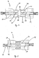
- Fig. 1 and Fig. 2 In the following, only a part, namely the housing half shell 4, designed as a connector housing lower part of the hermaphroditic connector housing 3 describe, since this is identical to the connector housing upper part.
- This consists of an electrical insulation material, preferably plastic and comprises a substantially planar housing bottom 9, each of which has a first housing wall 20 and a second housing wall 30 at the left and at the right edge, which protrude perpendicularly upwards from the housing bottom 9.
- the two housing walls 20, 30 extend in the rear portion along an arcuate housing wall portion 21. In the rear region extends a transverse web and connects the two housing walls 20 and 30 with each other.
- the housing crosspiece know a semicircular recess 42, which serves as a cable gland.
- the first housing wall 20 extends starting from the cable duct along the arcuate housing wall section 21 to a then substantially straight wall section. Following the arcuate housing wall portion 21 is a recess 23. This is followed by the straight housing wall portion at which extends upwards, so preferably perpendicular to the housing bottom 9, a wall web 24 is arranged.
- the wall web 24 know on its inward side a recess on.
- the wall thickness tapers abruptly, namely at an offset 26, which is found on the outer surface of the outer wall.
- the second housing wall 30 is arranged substantially mirror-inverted to the first housing wall 20 in its course and protrudes from the housing bottom 9 substantially vertically upwards, starting with an arcuate course at the rear end.
- a recess 34 over the entire height of the housing wall 30 correspondingly formed in its geometry to the mirror image arranged wall web 28.
- On the back of the wall web 28 is a not shown locking groove 29 which coincides with the locking lug 35 when mating two connector half-shells 4 lock. To complain about this later, as well as clearly in Fig. 2 to recognize which in Fig. 1 is rotated by 180 °, there is a wall web 31, which protrudes in height above the housing wall 30.
- a latching tab 37 which is arranged corresponding to the latching lug 22 and the recess 23.
- a further recess 32 are next to the wall web 31 towards plug-side end 10 of the housing part, a further recess 32, with another Latch 36, which is correspondingly formed to the wall web 24 of the first housing wall 20.
- a substantially U-shaped portion formed by the two housing wall sections with offset to the plug-side end and the front part of the housing bottom 9 in the middle web of the U-shaped portion has a further offset, namely a step 27.
- a plug contour which is formed so to speak of two L-shaped legs, which are arranged offset relative to each other via a step 27.
- a locking groove 43 In the left slightly deeper stepped area is a locking groove 43.
- a corresponding corresponding latching web 44 is formed, which is adapted to immerse in the locking groove 43.
- chamber wall webs 40 are arranged at a fixed distance from each other, which project as wall-like webs from the bottom 9 of the connector housing 4 upwards and, so to speak, chambers for the contacts 6, preferably for the terminal portions of the contacts 6 form.
- chambers for the contacts 6, preferably for the terminal portions of the contacts 6 form.
- four chambers formed by three chamber wall webs 40 and the two housing walls 20, 30, which define the two outer chambers.
- substantially cuboid Codierstege 41 for receiving the contact carrier on the housing bottom 9 are offset towards the front.
- This Codierstege are slightly widened in their width formed opposite the chamber wall webs 40th Die Codierstege 41 serve to receive and fix the in Fig. 4
- a hermaphroditic connector housing is obtained in a simple manner by locking identical housing halves 4 together, so that one to a hermaphroditic connector housing, as in Fig. 9 shown, which in turn represents itself as a hermaphroditic connector in the whole. Two of these mated housing pairs can be plugged together, and in Fig. 10 shown.
- the number of Kunststoffmmem and thus absorbable hermaphroditic contact carrier modules 7, can be constructed modular by appropriate geometric broadening of the housing 3.
- FIG Fig. 4 An embodiment of a hermaphroditic contact carrier module 7 is shown in FIG Fig. 4 displayed.
- a contact carrier module 7 is a substantially parallelepiped-shaped module with two parallel and substantially spaced and flat module walls 81, 82.
- an opening 74 Preferably in the central position of the contact carrier module 7 is an opening 74, which from the rear end to the front end of an inventive Contact carrier module 7 passes through, such that a contact, in accordance with Fig. 3 , Through this opening in such a contact carrier module 7 can be mounted by simple push-through mounting.
- the contact carrier module 7 has a lower contact carrier web 70, a middle contact carrier web 71 and an upper contact carrier web 72, which are arranged fork-like and parallel to one another in the plug-in direction when the contact carrier module is installed.
- the webs 70, 71, 72 extend in height substantially over the entire thickness of the contact carrier module 7.
- the upper contact carrier web 72 comprises a further, placed on this web 77, which is positively and materially connected to the upper contact carrier web 72.
- a contact channel 80 formed as a recess, over the entire length of the lower contact carrier web 70.
- recesses 76, 79 which are diametrically opposed.
- the opening 74 Between the upper recess 76, which is formed as a box-shaped recess, as in Fig. 4 and the lower recess 79, which is also formed as a box-shaped recess, there is the aforementioned opening 74.
- this opening 74 are two grooves for receiving a hermaphroditic contact 6, according to Fig. 3 appropriate.
- the hermaphroditic contact 6 is punched and formed as a stamped / bent part of a metal sheet.
- An example according to the invention, as in Fig. 3 shows a hermaphroditic contact formed with a terminal portion 60 and a Greierabexcellent 61. Between the two sections 60, 61 is a holding portion 66 which is formed substantially U-shaped.
- the first contact tongue 62 is formed as a substantially straight web
- the second contact tongue 62 connected to the diametrically opposite leg of the holding portion 66, connected parallel to the other.
- the second contact tongue 63 is formed in its front contacting region with a bent contacting portion 64.
- the otherwise substantially rectilinear second contact tongue 63 is as in here Fig. 3 darg Congress provided with a contact tip 65, the is produced by bending in the region of the bent contacting section 64. This results in a hermaphroditic contact, which can be mounted by means of simple push-through mounting in a contact carrier module 7 according to the invention.
- connection section 60 is designed here as a crimp connection region and forms a receptacle for a cable, not shown, to be connected.
- Fig. 5 By way of example, four hermaphroditic contact carrier modules are mounted in a housing part 4, in which four hermaphroditic contacts 6, according to FIG Fig. 3 are mounted by means of push-through mounting from the rear. Good to see is the location of the connecting portions 60 between the chamber wall webs 40. The hermaphroditic contacts 6 are so far inserted into the contact carrier modules 7 that they come with their stop 67 at an inner detent point of the contact carrier modules 7 to the plant. As a result, a fixed mounting position is achieved in the plugging direction.
- the chamber wall webs 40 simultaneously form a lateral limit stop for a contact surface of the connection portion 60. This simultaneously achieves a lateral hositionieriage the contacts 7 relative to the connector housing 3.
- the mode of action of hermaphroditic contact carrier modules with built-in contact is in the FIGS. 7 and 8 shown.
- An unmapped position is in Fig. 7 and an inserted position in Fig. 8 shown, In Fig.
- the contact carrier modules 7 are two contact carrier modules 7 rotated by 180 ° to each other with respect to each other, so that they are placed in a pluggable position.
- the contact carrier modules 7 are each equipped with a hermaphroditic contact 6, which protrude with its contact point 65 in the gap between the upper contact carrier web 72 and the central contact carrier web 71.
- the middle contact carrier web 71 is located in the illustration in Fig. 7 .
- the left contact carrier module arranged on the underside, also a contact channel, in which the contact tongue 62 is introduced and rests with its upper side. As a result, the contact tongue 62 is guided on the one hand in the middle contact carrier web 71 and on the other hand supported by this.
- the lower contact carrier web 70 lies with its groove 80 the corresponding contact carrier web 72 with its corresponding web 77 opposite, so that when mating, as in Fig. 8 shown, in each case the groove 77 of a contact carrier module dips into the groove 80 of the corresponding contact carrier module, so that the contact carrier modules 7 together with the hermaphroditic contact 6 itself as hermaphroditic plug-in system are formed.
- contact carrier modules are the resilient contact tongues 63 deflected from its rest position and slide on the corresponding contact tongue 62 of the opposite contact carrier module 7.
- a hermaphroditic connector which can be plugged so to speak with itself, so a second similar hermaphroditic connector, as in Fig. 10 shown in mated condition.
- the locking webs 44 cooperate with the locking grooves 43 so that the plug connector is securely held in its inserted position.
- the holding force of a hermaphroditic connector pair can be set and determine.
- two or more webs can be arranged side by side or offset from one another to achieve a higher holding force.
Description
Die Erfindung betrifft einen hermaphroditischen Steckverbinder beziehungsweise eine hermaphroditische Steckverbindung gemäß dem Oberbegriff des Anspruchs 1.The invention relates to a hermaphroditic connector or a hermaphroditic connector according to the preamble of
Die Erfindung betrifft daher ein modulares hermaphroditisches Steckverbindersystem mit einem hermaphroditischen Steckverbindergehäuse, hermaphroditischen Kontakten, sowie hermaphroditischen modularen Kontaktträgern. Hermaphroditische Steckverbindersysteme sind bereits im Stand der Technik bekannt.The invention therefore relates to a modular hermaphroditic connector system having a hermaphroditic connector housing, hermaphroditic contacts, and hermaphroditic modular contact carriers. Hermaphroditic connector systems are already known in the art.
Aus der
Daneben ist aus der
Des Weiteren ist im Stand der Technik ein elektrischer Zwitterkontakt aus Kontaktblech bekannt, bei dem zwei federnde Kontaktarme über einem Aufnahmeteil liegen, der zwei beabstandete, miteinander verbundene Seitenwände aufweist, die einen Kanal bilden, wobei die Seitenwände so voneinander beabstandet sind, dass sie zwischen sich die Kontaktarme eines identischen ausgebildeten Zwitterkontaktes aufnehmen und mit diesem in Anlage gelangen.Further known in the art is a contact plate electrical hermetic contact in which two resilient contact arms overlay a receiving member having two spaced, interconnected side walls forming a channel, the side walls being spaced apart therebetween pick up the contact arms of an identical trained hermaphroditic contact and get into contact with this.
Ferner ist aus der
Aus der
Die im Stand der Technik bekannten hermaphroditischen Steckerkontakte eignet sich nicht in einfacher Weise zum Aufbau eines modularen Steckverbindersystems, bei dem auch im Montagefall eine einfache Montage und Demontage des Steckverbinders und darüber hinaus auch der Austausch eines einzelnen Kontaktes möglich sein soll. Der Erfindung liegt daher die Aufgabe zugrunde, ein hermaphroditisches Steckverbindersystem beziehungsweise einen hermaphroditischen Steckverbinder der eingangs genannten Art zu schaffen, welcher durch eine geringe Anzahl von Teilen charakterisiert ist, die zumal modular aufbaubar sind und möglichst einfach herzustellen sind. Weltere Aufgabe der vorliegenden Erfindung ist es dabei, einen hermaphroditischen Kontakt bereitzustellen, so dass zwei unterschiedliche Kontakte, nämlich je ein Buchsen- und ein Stiftkontakt vermieden werden können und so zu sagen nur ein Kontakttyp bei dieser Art der Steckverbindung notwendig ist. Weitere Aufgabe der vorliegenden Erfindung ist es, den hermaphroditischen Steckverbinder so zu gestalten, dass durch einfaches Skalieren der Konturen des übergeordneten Steckverbindergehäuses eine Vielzahl von hermaphroditischen Kontakten in dem Gehäuse untergebracht werden können und dabei keine weiteren zusätzlichen Teile benötigt werden. Diese Aufgabe wird erfindungsgemäß durch den Gegenstand von Anspruch 1 gelöst, nämlich dadurch, dass das Steckverbindergehäuse, sowie die Kontaktträger und die darin befindlichen Kontakten alle hermaphroditisch ausgebildet sind. Weitere vorteilhafte Ausgestaltungen der Erfindungen sind in den Unteransprüchen angegeben.The hermaphroditic plug contacts known in the prior art are not suitable in a simple manner to build a modular connector system in which a simple assembly and disassembly of the connector and also the replacement of a single contact should be possible even in the case of installation. The invention is therefore an object of the invention to provide a hermaphroditic connector system or a hermaphroditic connector of the type mentioned, which is characterized by a small number of parts, which are particularly modular and modular as easy to manufacture. It is a world-wide object of the present invention to provide a hermaphroditic contact, so that two different contacts, namely one socket and one pin contact each can be avoided and so to say only one type of contact is necessary in this type of connector. Another object of the present invention is to make the hermaphroditic connector so that by simply scaling the contours of the parent connector housing a plurality of hermaphroditic contacts can be accommodated in the housing and no further additional parts are needed. This object is achieved by the subject matter of
Die mit der Erfindung erzielten Vorteile bestehen weiterhin darin, dass ein derartiger elektrischer, hermaphroditisch ausgebildeter Steckverbinder verwechslungssicher einsetzbar ist. Zudem hat ein derartiger hermaphroditischer Steckverbinder den Vorteil, lediglich zwei Grundbauteile lagermäßig vorhalten zu müssen und darüber hinaus jeweils für die Applikation oder die Anwendung notwendigen Umgehäuse, in die die Grundbauteile, nämlich die Kontaktmodule, sprich hermaphroditische Kontaktträgermodule und die hermaphroditischen Kontakte montiert werden können.The advantages achieved by the invention continue to be that such electrical, hermaphroditically trained connector is used confusion safe. In addition, such a hermaphroditic connector has the advantage only two basic components stocked to hold and beyond each necessary for the application or application housing in which the basic components, namely the contact modules, ie hermaphroditic contact carrier modules and the hermaphroditic contacts can be mounted.
Dabei ist der Zwitterkontakt aus einem einfachen Blech als Stanz-/Biegeteil so ausgeführt, dass dieses von hinten durch das erfindungsgemäße Kontaktträgermodule hindurch geschoben und eingeführt werden kann, wodurch bei einem Instandhaltungsfall der einzelne Kontakt auf einfache Weise gewechselt werden kann.In this case, the hermaphroditic contact is made of a simple sheet metal as a punched / bent part so that it can be pushed and inserted from behind through the contact carrier modules according to the invention, whereby in a maintenance case the individual contact can be changed in a simple manner.
Ein Ausführungsbeispiel der Erfindung ist in der Zeichnung dargestellt und wir im Folgenden näher erläutert. Es zeigen:
-
Fig. 1 eine perspektivische Ansicht eines Teiles eines hermaphroditischen Steckverbindergehäuses (hier als Unterteil dargestellt), -
Fig. 2 ein identisches, wie inFig. 1 gezeigtes hermaphroditisches Steckverbindergehäuseteil (hier als Oberteil gezeigt), -
Fig. 3 zeigt eine perspektivische Ansicht eines herrnaphroditischen Kontaktes, -
Fig. 4 zeigt die perspektivische Ansicht von schräg hinten eines hermaphroditischen Kontaktträgermoduls, -
Fig. 5 zeigt die halboffene perspektivische Ansicht eines hermaphroditischen Steckverbindergehäuses mit eingesetzten Kontaktträgermodulen und Kontakten, -
Fig. 6 zeigt eine Ansicht gemäl3Fig. 5 von oben, -
Fig. 7 zeigt die seitliche und halbtransparente Ansicht eines nicht gesteckten hermaphroditischen Kontaktträgermodulpaares, -
Fig. 8 ist eine Ansicht entsprechendFig. 7 im gesteckten Zustand, -
Fig. 9 zeigt ein hermaphroditisches Steckverbinderpaar mit eingesetzten Kontaktträgermodulen in perspektivischer Ansicht, -
Fig..10 ist eine Ansicht gemäßFig. 9 im gesteckten Zustand.
-
Fig. 1 a perspective view of a part of a hermaphroditic connector housing (shown here as a lower part), -
Fig. 2 an identical, as inFig. 1 shown hermaphroditic connector housing part (shown here as a top), -
Fig. 3 shows a perspective view of a Herrnaphroditic contact, -
Fig. 4 shows the perspective view obliquely from the back of a hermaphroditic contact carrier module, -
Fig. 5 shows the half-open perspective view of a hermaphroditic connector housing with inserted contact carrier modules and contacts, -
Fig. 6 shows a view gemäl3Fig. 5 from above, -
Fig. 7 shows the lateral and semi-transparent view of an unmated hermaphroditic contact carrier module pair, -
Fig. 8 is a view accordinglyFig. 7 when plugged in, -
Fig. 9 shows a hermaphroditic connector pair with inserted contact carrier modules in perspective view, -
Fig..10 is a view according toFig. 9 in mated condition.
In
Die zweite Gehäusewand 30 ist im Wesentlichen spiegelbildlich zur ersten Gehäusewand 20 in ihrem Verlauf angeordnet und ragt ebenso von dem Gehäuseboden 9 im Wesentlichen senkrecht nach oben, beginnend mit einem bogenförmigen Verlauf am hinteren Ende. Am Beginn des bogenförmigen Verlaufes befindet sich eine Ausnehmung 34 über die gesamte Höhe der Gehäusewand 30 korrespondierend in seiner Geometrie ausgebildet zu dem spiegelbildlich angeordneten Wandsteg 28. Auf der Rückseite des Wandsteges 28 befindet sich eine nicht dargestellte Rastnut 29, die mit der Rastnase 35 beim Zusammenstecken zweier Steckverbinderhalbschalen 4 verrasten. Dazu beanstandet im weiteren Verlauf, wie auch deutlich in
Am Gehäuseboden 9 sind Kammerwandstege 40 in einem festen Abstand zueinander angeordnet, welche als wandartige Stege vom Boden 9 des Steckverbindergehäuses 4 nach oben ragen und sozusagen Kammern für die Kontakte 6, vorzugsweise für die Anschlussbereiche der Kontakte 6, bilden. In dem in
Ein Ausführungsbeispiel eines hermaphroditischen Kontaktträgermoduls 7 ist in der
- 11
- Hermaphroditischer SteckverbinderHermaphroditic connector
- 22
- Hermaphroditisches SteckverbinderpaarHermaphroditic connector pair
- 33
- Hermaphroditisches SteckverbindergehäuseHermaphroditic connector housing
- 44
- GehäusehalbschaleHousing shell
- 66
- Hermaphroditischer KontaktHermaphroditic contact
- 77
- Hermaphroditisches KontaktträgermodulHermaphroditic contact carrier module
- 88th
- Gehäusewandhousing wall
- 99
- Gehäusebodencaseback
- 1010
- stedcseitiges Endestedcseitiges end
- 2020
- erste Gehäusewandfirst housing wall
- 2121
- bogenförmiger Gehäusewandabschnittarcuate housing wall section
- 2222
- Rastnaselocking lug
- 2323
- Ausnehmungrecess
- 2424
- Wandstegwall web
- 2525
- Ausnehmungrecess
- 2626
- Versatz (an der Außenfläche)Offset (on the outer surface)
- 2727
- Stufestep
- 2828
- Wandstegwall web
- 2929
- Rastnutlocking groove
- 3030
- zweite Gehäusewandsecond housing wall
- 3131
- Wandstegwall web
- 3232
- Ausnehmungrecess
- 3333
- Versatz (an der Innenfläche)Offset (on the inner surface)
- 3434
- Ausnehmungrecess
- 35,3635.36
- Rastnasenlocking lugs
- 3737
- Rastlaschesnap tab
- 3838
- Radiusradius
- 4040
- KammerwandstegeChamber wall webs
- 4141
- Codierstegepegs at
- 4242
- Ausnehmungrecess
- 4343
- Rastnutlocking groove
- 4444
- Raststeglatching web
- 6060
- Anschlussabschnittconnecting section
- 6161
- Kontaktierabschnittcontacting section
- 6262
- erste Kontaktzungefirst contact tongue
- 6363
- zweite Kontaktzungesecond contact tongue
- 6464
- gebogener Kontaktzungenabschnittcurved contact tongue section
- 6565
- Kontaktkuppecontact cusp
- 6666
- Halteabschnittholding section
- 6767
- Anschlagattack
- 7070
- unterer Kontaktträgersteglower contact carrier bar
- 7171
- mittlerer Kontaktträgerstegmiddle contact carrier bar
- 7171
- oberer Kontaktträgerstegupper contact carrier bar
- 7474
- Öffnung/DurchbruchOpening / Breakthrough
- 7575
- Längsnutelongitudinal groove
- 7676
- Ausnehmungrecess
- 7777
- Stegweb
- 7878
- Anschlagattack
- 7979
- Ausnehmungrecess
- 8080
- Nutgroove
- 81, 8281, 82
- Modulwändemodule walls
Claims (13)
- Hermaphrodite plug-type connector (1) comprising a plug-type connector housing (3) having a plurality of hermaphrodite contacts (6) which each have a connection section (60) for connection of a cable at an end which is averted from the contact-making section (64), characterized in that the hermaphrodite plug-type connector (1) comprises at least one hermaphrodite contact carrier module (7) which is arranged in the plug-type connector housing (3), and in that the plug-type connector housing (3) consists of two hermaphrodite housing half-shells.
- Hermaphrodite plug-type connector (1) according to Claim 1, characterized in that at least one hermaphrodite contact (6) is arranged in at least one contact carrier module (7).
- Hermaphrodite plug-type connector (1) according to Claim 1 or 2,
characterized in that a plurality of hermaphrodite contact carrier modules (7) are arranged next to one another in the plug-type connector housing (3). - Hermaphrodite plug-type connector (1) according to one of the preceding claims, characterized in that the housing half-shells (4) each have side walls (20, 30), at least one wall web (24, 28, 31) projecting beyond each of the said side walls.
- Hermaphrodite plug-type connector (1) according to Claim 4, characterized in that at least one latching tab (29, 37) is integrally formed on each of the wall webs (24, 28, 31).
- Hermaphrodite plug-type connector (1) according to Claim 4 or 5,
characterized in that the latching lugs (22, 35, 36) are arranged on the outer faces of the housing walls (20, 30). - Hermaphrodite plug-type connector (1) according to Claim 6, characterized in that the latching lugs (22, 35, 36) are arranged in recesses (23, 32, 34) on the housing walls (20, 30).
- Hermaphrodite plug-type connector (1) according to one of the preceding claims, characterized in that a step (27) is arranged transverse to the plug-in direction of the plug-type connector at the plug-in end (10) of the plug-type connector housing (3), wherein at least two regions with inner and outer surfaces which are offset in relation to one another are connected to one another by the step (27).
- Hermaphrodite plug-type connector (1) according to one of the preceding claims, characterized in that the hermaphrodite contacts (6) have two spring-action contact tongues (62, 63) which run parallel in relation to one another.
- Hermaphrodite plug-type connector (1) according to Claim 9, characterized in that a contact dome (65) which is bent in the direction of the contact tongue (62) is formed at the end of the contact tongue (63).
- Hermaphrodite plug-type connector (1) according to Claim 9 or 10, characterized in that that side of the contact tongue (62) which faces the contact tongue (63) is supported on the contact carrier module (7) in the fitted state.
- Hermaphrodite plug-type connector (1) according to Claim 10 or 11, characterized in that that side of the contact tongue (62) which is averted from the contact tongue (63) makes contact with contact dome (65) of the contact tongue (63) of the corresponding mating plug in the plug-connected state of the hermaphrodite plug-type connector.
- Hermaphrodite plug-type connector (1) according to one of the preceding claims, characterized in that the contact carrier modules (7) have webs which extend in the plug-in direction of the plug-type connector in the direction of the plug-in end (10) in the fitted state.
Applications Claiming Priority (1)
| Application Number | Priority Date | Filing Date | Title |
|---|---|---|---|
| DE102007053722A DE102007053722B4 (en) | 2007-11-10 | 2007-11-10 | Hermaphroditic connector |
Publications (3)
| Publication Number | Publication Date |
|---|---|
| EP2058904A2 EP2058904A2 (en) | 2009-05-13 |
| EP2058904A3 EP2058904A3 (en) | 2011-08-17 |
| EP2058904B1 true EP2058904B1 (en) | 2016-10-19 |
Family
ID=40342750
Family Applications (1)
| Application Number | Title | Priority Date | Filing Date |
|---|---|---|---|
| EP08019500.1A Not-in-force EP2058904B1 (en) | 2007-11-10 | 2008-11-07 | Hermaphrodite plug-in connector |
Country Status (2)
| Country | Link |
|---|---|
| EP (1) | EP2058904B1 (en) |
| DE (1) | DE102007053722B4 (en) |
Families Citing this family (12)
| Publication number | Priority date | Publication date | Assignee | Title |
|---|---|---|---|---|
| CN102437469B (en) * | 2011-09-19 | 2013-07-17 | 四川华丰企业集团有限公司 | Rapid wire-protecting box for connector |
| EP3641074A1 (en) * | 2013-09-25 | 2020-04-22 | Virginia Panel Corporation | High speed data module for high life cycle interconnect device |
| US9685727B2 (en) | 2013-09-25 | 2017-06-20 | Virginia Panel Corporation | High speed data contact set with right angle termination insert |
| DE202014101121U1 (en) * | 2014-03-12 | 2014-03-20 | Amphenol-Tuchel Electronics Gmbh | Connector alignment module and modular connector with connector alignment module |
| NO2780523T3 (en) | 2014-06-25 | 2018-03-24 | ||
| USD759606S1 (en) | 2014-09-25 | 2016-06-21 | Virginia Panel Corporation | Contact extraction tool |
| USD765047S1 (en) | 2014-11-11 | 2016-08-30 | Virginia Panel Corporation | Contact extraction tool |
| DE102014119220A1 (en) * | 2014-12-19 | 2016-06-23 | Amphenol-Tuchel Electronics Gmbh | Hermaphroditic connector |
| US9551483B1 (en) | 2015-07-01 | 2017-01-24 | Tyco Electronics Corporation | Multiple cable disconnect |
| US9680268B1 (en) * | 2016-05-18 | 2017-06-13 | Itt Manufacturing Enterprises Llc | Genderless electrical connectors |
| CN110148854B (en) * | 2019-05-30 | 2024-02-27 | 厦门广泓工贸有限公司 | Electric connection terminal and male-female mutual power distribution connector applied to same |
| CN114498168B (en) * | 2022-01-24 | 2024-02-20 | 鹤山市得润电子科技有限公司 | Connector, connector assembly and electronic equipment |
Family Cites Families (12)
| Publication number | Priority date | Publication date | Assignee | Title |
|---|---|---|---|---|
| DE1177231B (en) | 1962-05-25 | 1964-09-03 | Harting Elektro W | Contact piece for electrical plug connections |
| ES175163Y (en) | 1968-09-23 | 1973-02-16 | Amp, Incorporated | A MALE AND FEMALE CONTACT DEVICE MADE OF SHEET - METALLIC. |
| FR2223856B1 (en) * | 1973-03-26 | 1976-12-03 | Bendix Corp | |
| US4061406A (en) | 1974-08-28 | 1977-12-06 | Amp Incorporated | High current carrying connector |
| CA1105815A (en) | 1977-06-17 | 1981-07-28 | Paul-Emile Bonneau | Red blood cell labelling kit |
| US5035639A (en) * | 1990-03-20 | 1991-07-30 | Amp Incorporated | Hermaphroditic electrical connector |
| US5183409A (en) | 1991-04-15 | 1993-02-02 | Eric Clever | Hermaphroditic multiple contact connector |
| FR2719706B1 (en) | 1994-05-03 | 1996-05-31 | Cinch Connecteurs Sa | Hermaphroditic electrical contact member. |
| JPH1027646A (en) * | 1996-07-12 | 1998-01-27 | Sumitomo Wiring Syst Ltd | Connector |
| JP3146982B2 (en) * | 1996-07-12 | 2001-03-19 | 住友電装株式会社 | connector |
| DE29618214U1 (en) * | 1996-10-22 | 1996-12-05 | Maxi System Int Sa | plug |
| CN1228891C (en) * | 2001-01-29 | 2005-11-23 | 蒂科电子公司 | High-density plug connector for twisted pair cable |
-
2007
- 2007-11-10 DE DE102007053722A patent/DE102007053722B4/en not_active Expired - Fee Related
-
2008
- 2008-11-07 EP EP08019500.1A patent/EP2058904B1/en not_active Not-in-force
Non-Patent Citations (1)
| Title |
|---|
| None * |
Also Published As
| Publication number | Publication date |
|---|---|
| EP2058904A3 (en) | 2011-08-17 |
| DE102007053722A1 (en) | 2009-05-20 |
| EP2058904A2 (en) | 2009-05-13 |
| DE102007053722B4 (en) | 2011-08-25 |
Similar Documents
| Publication | Publication Date | Title |
|---|---|---|
| EP2058904B1 (en) | Hermaphrodite plug-in connector | |
| EP2690716B1 (en) | Electrical connecting element | |
| EP2182592B1 (en) | Connector | |
| DE10126957B4 (en) | Plug connection with means for preventing an incompletely connected state | |
| DE10121654B4 (en) | Box-shaped contact with stress limitation | |
| EP3480898B1 (en) | Modular mounting frame for electrical connectors | |
| EP3293833B1 (en) | Current rail connector | |
| DE102011056043B4 (en) | Stromschienenabgriffelement | |
| EP2018684A1 (en) | Module with connectors for actuators and/or sensors | |
| DE102006062742B4 (en) | Electrical blade receptacle | |
| EP0865105B1 (en) | Female electrical contact with contact spring and use as a terminal contact | |
| DE10244946B4 (en) | Contact socket for an electrical plug connection | |
| DE4205974C1 (en) | Electrical plug connector with built-in latching for pins - provides section formed on housing that locates against pin flange and is held by latch stage | |
| DE102006009357B3 (en) | Electrical blade receptacle for contacting e.g. electrical fan connector, has contact boxes that are arranged next to each other such that contact blade is electrically contacted by contact spring in plugging position | |
| EP1154521B1 (en) | Connetor and mounting method of a connector | |
| DE102012218028A1 (en) | Plug and kit for a plug | |
| EP1819019A1 (en) | Plug and socket for an electric plug and socket connection and electric plug and socket assembly with such a plug and socket | |
| EP1720222B1 (en) | Electrical connector, particularly for airbag ignition systems | |
| DE19914308A1 (en) | Electrical connector for insulated or stripped wire | |
| EP2837064B1 (en) | Connector set and connector and mating connector therefor | |
| EP1923960B1 (en) | Blade receptacle | |
| DE102005054590A1 (en) | Electrical pluggable connector e.g. for circuit boards, has convex surfaces of spring limbs of contacts facing opposite one another | |
| EP0527332B1 (en) | Jack with resilient one-piece guide means | |
| DE102018125366A1 (en) | Contact socket, socket strip and electrical assembly | |
| DE102017213105A1 (en) | Electrical contact housing for simplified contact assemblage |
Legal Events
| Date | Code | Title | Description |
|---|---|---|---|
| PUAI | Public reference made under article 153(3) epc to a published international application that has entered the european phase |
Free format text: ORIGINAL CODE: 0009012 |
|
| AK | Designated contracting states |
Kind code of ref document: A2 Designated state(s): AT BE BG CH CY CZ DE DK EE ES FI FR GB GR HR HU IE IS IT LI LT LU LV MC MT NL NO PL PT RO SE SI SK TR |
|
| AX | Request for extension of the european patent |
Extension state: AL BA MK RS |
|
| PUAL | Search report despatched |
Free format text: ORIGINAL CODE: 0009013 |
|
| AK | Designated contracting states |
Kind code of ref document: A3 Designated state(s): AT BE BG CH CY CZ DE DK EE ES FI FR GB GR HR HU IE IS IT LI LT LU LV MC MT NL NO PL PT RO SE SI SK TR |
|
| AX | Request for extension of the european patent |
Extension state: AL BA MK RS |
|
| RIC1 | Information provided on ipc code assigned before grant |
Ipc: H01R 13/28 20060101AFI20110712BHEP Ipc: H01R 13/506 20060101ALI20110712BHEP |
|
| AKY | No designation fees paid | ||
| REG | Reference to a national code |
Ref country code: DE Ref legal event code: R108 Effective date: 20120425 |
|
| 17P | Request for examination filed |
Effective date: 20120218 |
|
| RBV | Designated contracting states (corrected) |
Designated state(s): AT BE BG CH CY CZ DE DK EE ES FI FR GB GR HR HU IE IS IT LI LT LU LV MC MT NL NO PL PT RO SE SI SK TR |
|
| RIC1 | Information provided on ipc code assigned before grant |
Ipc: H01R 13/28 20060101AFI20150930BHEP Ipc: H01R 13/514 20060101ALN20150930BHEP Ipc: H01R 13/506 20060101ALI20150930BHEP |
|
| RIC1 | Information provided on ipc code assigned before grant |
Ipc: H01R 13/514 20060101ALN20151014BHEP Ipc: H01R 13/506 20060101ALI20151014BHEP Ipc: H01R 24/84 20110101ALI20151014BHEP Ipc: H01R 13/28 20060101AFI20151014BHEP |
|
| 17Q | First examination report despatched |
Effective date: 20151030 |
|
| GRAP | Despatch of communication of intention to grant a patent |
Free format text: ORIGINAL CODE: EPIDOSNIGR1 |
|
| RIC1 | Information provided on ipc code assigned before grant |
Ipc: H01R 13/514 20060101ALN20160623BHEP Ipc: H01R 24/84 20110101ALI20160623BHEP Ipc: H01R 13/28 20060101AFI20160623BHEP Ipc: H01R 13/506 20060101ALI20160623BHEP |
|
| INTG | Intention to grant announced |
Effective date: 20160707 |
|
| GRAS | Grant fee paid |
Free format text: ORIGINAL CODE: EPIDOSNIGR3 |
|
| GRAA | (expected) grant |
Free format text: ORIGINAL CODE: 0009210 |
|
| AK | Designated contracting states |
Kind code of ref document: B1 Designated state(s): AT BE BG CH CY CZ DE DK EE ES FI FR GB GR HR HU IE IS IT LI LT LU LV MC MT NL NO PL PT RO SE SI SK TR |
|
| REG | Reference to a national code |
Ref country code: GB Ref legal event code: FG4D Free format text: NOT ENGLISH |
|
| REG | Reference to a national code |
Ref country code: CH Ref legal event code: EP |
|
| REG | Reference to a national code |
Ref country code: AT Ref legal event code: REF Ref document number: 839053 Country of ref document: AT Kind code of ref document: T Effective date: 20161115 |
|
| REG | Reference to a national code |
Ref country code: IE Ref legal event code: FG4D Free format text: LANGUAGE OF EP DOCUMENT: GERMAN |
|
| REG | Reference to a national code |
Ref country code: DE Ref legal event code: R096 Ref document number: 502008014717 Country of ref document: DE |
|
| REG | Reference to a national code |
Ref country code: NL Ref legal event code: MP Effective date: 20161019 |
|
| REG | Reference to a national code |
Ref country code: LT Ref legal event code: MG4D |
|
| PG25 | Lapsed in a contracting state [announced via postgrant information from national office to epo] |
Ref country code: LV Free format text: LAPSE BECAUSE OF FAILURE TO SUBMIT A TRANSLATION OF THE DESCRIPTION OR TO PAY THE FEE WITHIN THE PRESCRIBED TIME-LIMIT Effective date: 20161019 Ref country code: BE Free format text: LAPSE BECAUSE OF NON-PAYMENT OF DUE FEES Effective date: 20161130 |
|
| PG25 | Lapsed in a contracting state [announced via postgrant information from national office to epo] |
Ref country code: LT Free format text: LAPSE BECAUSE OF FAILURE TO SUBMIT A TRANSLATION OF THE DESCRIPTION OR TO PAY THE FEE WITHIN THE PRESCRIBED TIME-LIMIT Effective date: 20161019 Ref country code: NO Free format text: LAPSE BECAUSE OF FAILURE TO SUBMIT A TRANSLATION OF THE DESCRIPTION OR TO PAY THE FEE WITHIN THE PRESCRIBED TIME-LIMIT Effective date: 20170119 Ref country code: GR Free format text: LAPSE BECAUSE OF FAILURE TO SUBMIT A TRANSLATION OF THE DESCRIPTION OR TO PAY THE FEE WITHIN THE PRESCRIBED TIME-LIMIT Effective date: 20170120 Ref country code: SE Free format text: LAPSE BECAUSE OF FAILURE TO SUBMIT A TRANSLATION OF THE DESCRIPTION OR TO PAY THE FEE WITHIN THE PRESCRIBED TIME-LIMIT Effective date: 20161019 |
|
| PG25 | Lapsed in a contracting state [announced via postgrant information from national office to epo] |
Ref country code: NL Free format text: LAPSE BECAUSE OF FAILURE TO SUBMIT A TRANSLATION OF THE DESCRIPTION OR TO PAY THE FEE WITHIN THE PRESCRIBED TIME-LIMIT Effective date: 20161019 Ref country code: HR Free format text: LAPSE BECAUSE OF FAILURE TO SUBMIT A TRANSLATION OF THE DESCRIPTION OR TO PAY THE FEE WITHIN THE PRESCRIBED TIME-LIMIT Effective date: 20161019 Ref country code: PT Free format text: LAPSE BECAUSE OF FAILURE TO SUBMIT A TRANSLATION OF THE DESCRIPTION OR TO PAY THE FEE WITHIN THE PRESCRIBED TIME-LIMIT Effective date: 20170220 Ref country code: PL Free format text: LAPSE BECAUSE OF FAILURE TO SUBMIT A TRANSLATION OF THE DESCRIPTION OR TO PAY THE FEE WITHIN THE PRESCRIBED TIME-LIMIT Effective date: 20161019 Ref country code: IS Free format text: LAPSE BECAUSE OF FAILURE TO SUBMIT A TRANSLATION OF THE DESCRIPTION OR TO PAY THE FEE WITHIN THE PRESCRIBED TIME-LIMIT Effective date: 20170219 Ref country code: ES Free format text: LAPSE BECAUSE OF FAILURE TO SUBMIT A TRANSLATION OF THE DESCRIPTION OR TO PAY THE FEE WITHIN THE PRESCRIBED TIME-LIMIT Effective date: 20161019 Ref country code: FI Free format text: LAPSE BECAUSE OF FAILURE TO SUBMIT A TRANSLATION OF THE DESCRIPTION OR TO PAY THE FEE WITHIN THE PRESCRIBED TIME-LIMIT Effective date: 20161019 |
|
| REG | Reference to a national code |
Ref country code: DE Ref legal event code: R119 Ref document number: 502008014717 Country of ref document: DE |
|
| REG | Reference to a national code |
Ref country code: CH Ref legal event code: PL |
|
| PG25 | Lapsed in a contracting state [announced via postgrant information from national office to epo] |
Ref country code: MC Free format text: LAPSE BECAUSE OF FAILURE TO SUBMIT A TRANSLATION OF THE DESCRIPTION OR TO PAY THE FEE WITHIN THE PRESCRIBED TIME-LIMIT Effective date: 20161019 Ref country code: CH Free format text: LAPSE BECAUSE OF NON-PAYMENT OF DUE FEES Effective date: 20161130 Ref country code: LI Free format text: LAPSE BECAUSE OF NON-PAYMENT OF DUE FEES Effective date: 20161130 Ref country code: SK Free format text: LAPSE BECAUSE OF FAILURE TO SUBMIT A TRANSLATION OF THE DESCRIPTION OR TO PAY THE FEE WITHIN THE PRESCRIBED TIME-LIMIT Effective date: 20161019 Ref country code: CZ Free format text: LAPSE BECAUSE OF FAILURE TO SUBMIT A TRANSLATION OF THE DESCRIPTION OR TO PAY THE FEE WITHIN THE PRESCRIBED TIME-LIMIT Effective date: 20161019 Ref country code: RO Free format text: LAPSE BECAUSE OF FAILURE TO SUBMIT A TRANSLATION OF THE DESCRIPTION OR TO PAY THE FEE WITHIN THE PRESCRIBED TIME-LIMIT Effective date: 20161019 Ref country code: DK Free format text: LAPSE BECAUSE OF FAILURE TO SUBMIT A TRANSLATION OF THE DESCRIPTION OR TO PAY THE FEE WITHIN THE PRESCRIBED TIME-LIMIT Effective date: 20161019 Ref country code: EE Free format text: LAPSE BECAUSE OF FAILURE TO SUBMIT A TRANSLATION OF THE DESCRIPTION OR TO PAY THE FEE WITHIN THE PRESCRIBED TIME-LIMIT Effective date: 20161019 |
|
| REG | Reference to a national code |
Ref country code: IE Ref legal event code: MM4A |
|
| PLBE | No opposition filed within time limit |
Free format text: ORIGINAL CODE: 0009261 |
|
| REG | Reference to a national code |
Ref country code: FR Ref legal event code: ST Effective date: 20170731 |
|
| STAA | Information on the status of an ep patent application or granted ep patent |
Free format text: STATUS: NO OPPOSITION FILED WITHIN TIME LIMIT |
|
| PG25 | Lapsed in a contracting state [announced via postgrant information from national office to epo] |
Ref country code: IT Free format text: LAPSE BECAUSE OF FAILURE TO SUBMIT A TRANSLATION OF THE DESCRIPTION OR TO PAY THE FEE WITHIN THE PRESCRIBED TIME-LIMIT Effective date: 20161019 |
|
| 26N | No opposition filed |
Effective date: 20170720 |
|
| GBPC | Gb: european patent ceased through non-payment of renewal fee |
Effective date: 20170119 |
|
| PG25 | Lapsed in a contracting state [announced via postgrant information from national office to epo] |
Ref country code: LU Free format text: LAPSE BECAUSE OF NON-PAYMENT OF DUE FEES Effective date: 20161130 |
|
| PG25 | Lapsed in a contracting state [announced via postgrant information from national office to epo] |
Ref country code: FR Free format text: LAPSE BECAUSE OF NON-PAYMENT OF DUE FEES Effective date: 20161219 |
|
| PG25 | Lapsed in a contracting state [announced via postgrant information from national office to epo] |
Ref country code: DE Free format text: LAPSE BECAUSE OF NON-PAYMENT OF DUE FEES Effective date: 20170601 Ref country code: GB Free format text: LAPSE BECAUSE OF NON-PAYMENT OF DUE FEES Effective date: 20170119 Ref country code: SI Free format text: LAPSE BECAUSE OF FAILURE TO SUBMIT A TRANSLATION OF THE DESCRIPTION OR TO PAY THE FEE WITHIN THE PRESCRIBED TIME-LIMIT Effective date: 20161019 Ref country code: IE Free format text: LAPSE BECAUSE OF NON-PAYMENT OF DUE FEES Effective date: 20161107 |
|
| REG | Reference to a national code |
Ref country code: AT Ref legal event code: MM01 Ref document number: 839053 Country of ref document: AT Kind code of ref document: T Effective date: 20161107 |
|
| PG25 | Lapsed in a contracting state [announced via postgrant information from national office to epo] |
Ref country code: AT Free format text: LAPSE BECAUSE OF NON-PAYMENT OF DUE FEES Effective date: 20161107 |
|
| REG | Reference to a national code |
Ref country code: BE Ref legal event code: MM Effective date: 20161130 |
|
| PG25 | Lapsed in a contracting state [announced via postgrant information from national office to epo] |
Ref country code: HU Free format text: LAPSE BECAUSE OF FAILURE TO SUBMIT A TRANSLATION OF THE DESCRIPTION OR TO PAY THE FEE WITHIN THE PRESCRIBED TIME-LIMIT; INVALID AB INITIO Effective date: 20081107 Ref country code: CY Free format text: LAPSE BECAUSE OF FAILURE TO SUBMIT A TRANSLATION OF THE DESCRIPTION OR TO PAY THE FEE WITHIN THE PRESCRIBED TIME-LIMIT Effective date: 20161019 |
|
| PG25 | Lapsed in a contracting state [announced via postgrant information from national office to epo] |
Ref country code: TR Free format text: LAPSE BECAUSE OF FAILURE TO SUBMIT A TRANSLATION OF THE DESCRIPTION OR TO PAY THE FEE WITHIN THE PRESCRIBED TIME-LIMIT Effective date: 20161019 |
|
| PG25 | Lapsed in a contracting state [announced via postgrant information from national office to epo] |
Ref country code: BG Free format text: LAPSE BECAUSE OF FAILURE TO SUBMIT A TRANSLATION OF THE DESCRIPTION OR TO PAY THE FEE WITHIN THE PRESCRIBED TIME-LIMIT Effective date: 20161019 |
|
| PG25 | Lapsed in a contracting state [announced via postgrant information from national office to epo] |
Ref country code: MT Free format text: LAPSE BECAUSE OF FAILURE TO SUBMIT A TRANSLATION OF THE DESCRIPTION OR TO PAY THE FEE WITHIN THE PRESCRIBED TIME-LIMIT Effective date: 20161019 |