EP2428963A1 - Method for forming fine protrusions on cladding surface of nuclear fuel rod containing zirconium - Google Patents
Method for forming fine protrusions on cladding surface of nuclear fuel rod containing zirconium Download PDFInfo
- Publication number
- EP2428963A1 EP2428963A1 EP09844360A EP09844360A EP2428963A1 EP 2428963 A1 EP2428963 A1 EP 2428963A1 EP 09844360 A EP09844360 A EP 09844360A EP 09844360 A EP09844360 A EP 09844360A EP 2428963 A1 EP2428963 A1 EP 2428963A1
- Authority
- EP
- European Patent Office
- Prior art keywords
- cladding
- nuclear fuel
- fuel rod
- electrolyte solution
- nuclear
- Prior art date
- Legal status (The legal status is an assumption and is not a legal conclusion. Google has not performed a legal analysis and makes no representation as to the accuracy of the status listed.)
- Withdrawn
Links
Images




Classifications
-
- G—PHYSICS
- G21—NUCLEAR PHYSICS; NUCLEAR ENGINEERING
- G21C—NUCLEAR REACTORS
- G21C3/00—Reactor fuel elements and their assemblies; Selection of substances for use as reactor fuel elements
- G21C3/02—Fuel elements
- G21C3/04—Constructional details
- G21C3/06—Casings; Jackets
- G21C3/08—Casings; Jackets provided with external means to promote heat-transfer, e.g. fins, baffles
-
- G—PHYSICS
- G21—NUCLEAR PHYSICS; NUCLEAR ENGINEERING
- G21C—NUCLEAR REACTORS
- G21C3/00—Reactor fuel elements and their assemblies; Selection of substances for use as reactor fuel elements
- G21C3/02—Fuel elements
- G21C3/04—Constructional details
- G21C3/06—Casings; Jackets
-
- Y—GENERAL TAGGING OF NEW TECHNOLOGICAL DEVELOPMENTS; GENERAL TAGGING OF CROSS-SECTIONAL TECHNOLOGIES SPANNING OVER SEVERAL SECTIONS OF THE IPC; TECHNICAL SUBJECTS COVERED BY FORMER USPC CROSS-REFERENCE ART COLLECTIONS [XRACs] AND DIGESTS
- Y02—TECHNOLOGIES OR APPLICATIONS FOR MITIGATION OR ADAPTATION AGAINST CLIMATE CHANGE
- Y02E—REDUCTION OF GREENHOUSE GAS [GHG] EMISSIONS, RELATED TO ENERGY GENERATION, TRANSMISSION OR DISTRIBUTION
- Y02E30/00—Energy generation of nuclear origin
- Y02E30/30—Nuclear fission reactors
Definitions
- the present invention relates to a method for treating the surface of cladding of nuclear fuel rod.
- Zirconium having a melting point of 1,852 degrees Celsius and being chemically stable, has properties that it is greatly resistant to external corrosion.
- zirconium, a zircaloy, or zirconium oxide is used for goods or articles which are not to corrode, such as nuclear fuel rod coating film in a nuclear power plant, rustproof ceramic kitchen utensils, tools used for treating chemical medicines, and the like.
- nuclear fuel is covered by an aluminum or magnesium coating film so as to prevent nuclear wastes produced in the course of a nuclear fission from being mixed with a coolant and discharged to the outside.
- Zirconium having a melting point of 1,852 degrees Celsius and being chemically stable, has properties that it is greatly resistant to external corrosion.
- zirconium, a zircaloy, or zirconium oxide is used for goods or articles which are not to corrode, such as nuclear fuel rod coating film in a nuclear power plant, rustproof ceramic kitchen utensils, tools used for treating chemical medicines, and the like.
- nuclear fuel is covered by an aluminum or magnesium coating film so as to prevent nuclear wastes produced in the course of a nuclear fission from being mixed with a coolant and discharged to the outside.
- low-concentration enriched uranium dioxide (UO 2 ) powder is sintered into a cylindrical tablet having a diameter of 2 cm and height of 2 cm to create a dark brown pellet, which is then put into a thin metal tube having a thickness of 3mm clad (or coated) with a zircaloy which has good corrosion resistance to high temperature cooling water, and then both ends of the metal tubes are hermetically sealed.
- the cladding tube is formed to have a thickness of 1mm or smaller to facilitate thermal conduction.
- the temperature of the center of a fuel pellet is approximately 200°C
- the temperature of the surface of the fuel pellet is 600°C
- the temperatures of an inner surface and outer surface of a nuclear fuel rod are 400°C and 300°C, respectively.
- the present invention has been made in an effort to provide a method for forming roughness on an outer surface of cladding including zirconium to have hydrophilicity to thus improve stability of a nuclear fuel rod used in a nuclear power plant.
- An exemplary embodiment of the present invention provides a method for forming roughness on an outer surface of cladding of a nuclear fuel rod including zirconium, including: positioning the cladding of the nuclear fuel rod at a first electrode and connecting a positive electrode thereto, and positioning a conductive plate at a second electrode and connecting a negative electrode thereto; putting the cladding of the nuclear fuel rod in an electrolyte solution; and applying voltage to the positive electrode and the negative electrode to cause oxidation on the outer surface of the cladding of the nuclear fuel rod.
- the temperature of the electrolyte solution may be maintained at 10°C or lower.
- the method may be performed while maintaining the temperature of the electrolyte solution at a temperature range of 0°C to 10°C.
- the electrolyte solution may be a 0.01 wt% to 1.0 wt% of hydrofluoric acid (HF) solution.
- the voltage applied to the positive electrode and the negative electrode may be set to range from 20V to 40V in performing the method.
- Time for applying voltage to the positive electrode and negative electrode may be set to range from 10 minutes to 30 minutes in performing the method.
- hydrophilic oxide film having a fine structure can be formed on the outer surface of zirconium and zircaloy at a low cost through anodization compared with a method such as MEMS, or the like.
- the surface having a cylindrical shape such as a nuclear fuel rod can be easily processed to have hydrophilicity.
- the cladding of the nuclear fuel rod is formed to be hydrophilic, a contact angle with respect to a liquid can be reduced to increase heat transfer efficiency, and thus, the efficiency of a nuclear power plant can be improved.
- CHF critical heat flux
- the CHF refers to a point from which the outer surface temperature of the heater sharply goes up, while heat flux moving to a fluid is not further increased, in a state in which the heat flux is raised by operating the heater. If heating continues to pass this point, the heater, succumbing to the heat, will be broken, so in actuality, the heat engine is operated at a level lower than the CHF for the security.
- This principle may be applied for a nuclear power plant to make the outer surface of cladding of a nuclear fuel rod exposed to high temperature hydrophilic, to thereby raise the CHF and thus secure high stability.
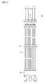
- FIG. 1 is a schematic view of a nuclear fuel rod constituting a fuel assembly used in a nuclear power plant
- FIG. 2 is a schematic view of a fuel assembly used in the nuclear power plant.
- Nuclear fuel rods 10, each including uranium dioxide (UO 2 ), may be arranged by 16x16 and fixed by spacer grids 21 and 23 to constitute a nuclear fuel assembly 20.
- the nuclear fuel rod 10 has a cylindrical shape.
- a plurality of cylindrical pellets 12 are accumulated in the nuclear fuel rod 10, and in order to prevent the pellets 12 from moving in the nuclear fuel rod 10, a compression spring 15 may be inserted at an upper side of the pellets 12.
- a cladding 17 forming an outer cover of the nuclear fuel rod 10 may be made of zircaloy, an alloy of tin and zirconium obtained by mixing chromium and iron.
- a method for changing chemical characteristics of the surface and a method for changing a surface shape in a microscale or in a nanoscale may be used, and in the present exemplary embodiment, the method of changing a surface shape in a microscale or in a nanoscale is employed.
- a micro/nano scale structure may be formed on the outer surface of the cladding of the nuclear fuel rod, while accelerating oxidation on the outer surface of the cladding electrochemically by applying anodization to the cladding.
- Anodization is advantageously applied to a large area, a curved surface, or the like, at a low cost, compared with an MEMS (microelectromechanical system) which incurs a great amount of seed investment cost because it basically requires a clean facility and uses photolithography which can be hardly applicable to a large area or a curved surface.
- MEMS microelectromechanical system
- the cladding of the nuclear fuel rod is positioned at a first electrode and a positive electrode is connected thereto, and a conductive plate is positioned at a second electrode and a negative electrode is connected thereto.
- a conductive plate made of platinum may be used as the conductive plate connected to the negative electrode.
- the nuclear fuel rod cladding connected to the positive electrode and the conductive plate connected to the negative electrode are put in an electrolyte solution.
- an electrolyte solution a hydrofluoric acid solution ranging from 0.01 wt% to 1.0 wt% may be used. If the hydrofluoric acid solution is less than 0.01 wt%, the speed of oxidation will be too slow to be actually applied, and if the hydrofluoric acid solution exceeds 1.0 wt%, an oxidized film of the nuclear fuel rod cladding will be wholly peeled off to have an electropolishing effect, so a hydrophilic surface cannot be obtained.
- the temperature to cause oxidation can be changed by regulating the temperature of external cooling water, and the temperature of the electrolyte solution may be maintained at 10°C or lower and can be maintained within a temperature range of 0°C to 10°C. If the temperature of the electrolyte solution is lower than 0°C, the speed of oxidation will be too slow to be actually applied, and if the temperature of the electrolyte solution is higher than 10°C, the oxidized film of the cladding of the nuclear fuel rod will be peeled off, failing to formation of a hydrophilic surface.
- the voltage applied to the positive electrode and the negative electrode may be selectively applied within the range of 20V to 40V, and time for applying the voltage to the positive electrode and the negative electrode may be set to range from 10 minutes to 30 minutes. If the application voltage is lower than 20V, the speed of oxidation will be too slow to be actually applied, 5and if the application voltage is higher than 40V, the oxidized film of the cladding of the nuclear fuel rod will be wholly peeled off to have an electropolishing effect, so a hydrophilic surface cannot be obtained.
- reaction time is less than 10 minutes, wettability of the outer surface of the cladding of the nuclear fuel rod is not sufficient, and if the reaction time exceeds 30 minutes, the oxidized film of the cladding of the nuclear fuel rod will be peeled off, a hydrophilic surface cannot be formed.
- the outer surface of the cladding has hydrophilicity having a contact angle of 10 degrees or some.
- the contact angle is obtained by measuring an angle between a surface of a droplet and a surface of a solid, such as metal, or the like, to which the droplet is attached.
- Nuclear fuel rod cladding made of a zircaloy was connected to a positive electrode, and a platinum plate was connected to a negative electrode, and anodization was performed by using a hydrofluoric acid (HF) solution as an electrolyte solution.
- the anodization was performed while changing the concentration of the electrolyte solution, the temperature of the electrolyte solution, an application voltage, and a reaction time as shown in Table 1 below.
- Table 1 Classification Electrolyte solution Temperature of electrolyte solution Applied voltage Reaction time Contact angle Exemplary Embodiment1 0.5wt% HF 10°C 30V 30 min. 8° Exemplary Embodiment2 0.5wt% HF 10°C 30V 20 min.
- Comparative Example 1 Anodization was not performed, while in Comparative Examples 2 and 3, anodization was performed under the conditions in which the temperature of an electrolyte solution was maintained at room temperature (25°C), the concentration of hydrofluoric acid solution was 0.5 wt% and 0.1 wt%, respectively, an application voltage was 5V, and a reaction time was 20 minutes and 30 minutes, respectively.
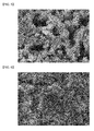
- FIGS. 3 and 4 The results of Exemplary Embodiment 1 are shown in FIGS. 3 and 4 , and the results of Exemplary Embodiments 2 and 3 are shown in FIGS. 5 and 6 , respectively.
- the results of Comparative Example 1 are shown in FIG. 7
- the results of Comparative Examples 2 and 3 are shown in FIGS. 8 and 9 , respectively.
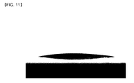
- the contact angle in Comparative Example 1 was measured to be approximately 70°, while that in Exemplary Embodiment 1 was measured to be approximately 8° and those in Exemplary Embodiments 2 and 3 were measured to be 10° and 12°, respectively.
Landscapes
- Physics & Mathematics (AREA)
- Engineering & Computer Science (AREA)
- Plasma & Fusion (AREA)
- General Engineering & Computer Science (AREA)
- High Energy & Nuclear Physics (AREA)
- Monitoring And Testing Of Nuclear Reactors (AREA)
- Other Surface Treatments For Metallic Materials (AREA)
- Chemical Treatment Of Metals (AREA)
- Electrical Discharge Machining, Electrochemical Machining, And Combined Machining (AREA)
Abstract
Description
- The present invention relates to a method for treating the surface of cladding of nuclear fuel rod.
- Zirconium, having a melting point of 1,852 degrees Celsius and being chemically stable, has properties that it is greatly resistant to external corrosion. Thus, zirconium, a zircaloy, or zirconium oxide is used for goods or articles which are not to corrode, such as nuclear fuel rod coating film in a nuclear power plant, rustproof ceramic kitchen utensils, tools used for treating chemical medicines, and the like.
- Meanwhile, nuclear fuel is covered by an aluminum or magnesium coating film so as to prevent nuclear wastes produced in the course of a nuclear fission from being mixed with a coolant and discharged to the outside. Zirconium, having a melting point of 1,852 degrees Celsius and being chemically stable, has properties that it is greatly resistant to external corrosion. Thus, zirconium, a zircaloy, or zirconium oxide is used for goods or articles which are not to corrode, such as nuclear fuel rod coating film in a nuclear power plant, rustproof ceramic kitchen utensils, tools used for treating chemical medicines, and the like.
- Meanwhile, nuclear fuel is covered by an aluminum or magnesium coating film so as to prevent nuclear wastes produced in the course of a nuclear fission from being mixed with a coolant and discharged to the outside. In case of a light-water nuclear reactor, low-concentration enriched uranium dioxide (UO2) powder is sintered into a cylindrical tablet having a diameter of 2 cm and height of 2 cm to create a dark brown pellet, which is then put into a thin metal tube having a thickness of 3mm clad (or coated) with a zircaloy which has good corrosion resistance to high temperature cooling water, and then both ends of the metal tubes are hermetically sealed.
- In general, tens to hundreds of the metal tubes are grouped to form a fuel assembly (or bundle) and the fuel assembly is used as a unit. Nuclear reactor includes hundreds of such assemblies. The cladding tube is formed to have a thickness of 1mm or smaller to facilitate thermal conduction. In the occurrence of nuclear fission, the temperature of the center of a fuel pellet is approximately 200°C, the temperature of the surface of the fuel pellet is 600°C, and the temperatures of an inner surface and outer surface of a nuclear fuel rod are 400°C and 300°C, respectively.
- Thus, if the fuel rod, exposed to high temperature, ruptures, nuclear fission products would be leaked out to potentially cause a serious problem, so continued efforts are required to enhance the stability.
- The present invention has been made in an effort to provide a method for forming roughness on an outer surface of cladding including zirconium to have hydrophilicity to thus improve stability of a nuclear fuel rod used in a nuclear power plant.
- An exemplary embodiment of the present invention provides a method for forming roughness on an outer surface of cladding of a nuclear fuel rod including zirconium, including: positioning the cladding of the nuclear fuel rod at a first electrode and connecting a positive electrode thereto, and positioning a conductive plate at a second electrode and connecting a negative electrode thereto; putting the cladding of the nuclear fuel rod in an electrolyte solution; and applying voltage to the positive electrode and the negative electrode to cause oxidation on the outer surface of the cladding of the nuclear fuel rod.
- The temperature of the electrolyte solution may be maintained at 10°C or lower. The method may be performed while maintaining the temperature of the electrolyte solution at a temperature range of 0°C to 10°C.
- The electrolyte solution may be a 0.01 wt% to 1.0 wt% of hydrofluoric acid (HF) solution. The voltage applied to the positive electrode and the negative electrode may be set to range from 20V to 40V in performing the method.
- Time for applying voltage to the positive electrode and negative electrode may be set to range from 10 minutes to 30 minutes in performing the method.
- According to an embodiment of the present invention, in the method for forming roughness on the outer surface of the cladding of the nuclear fuel rod including zirconium, hydrophilic oxide film having a fine structure can be formed on the outer surface of zirconium and zircaloy at a low cost through anodization compared with a method such as MEMS, or the like.
- In addition, because even a large curved surface can be processed through anodization, the surface having a cylindrical shape such as a nuclear fuel rod can be easily processed to have hydrophilicity.
- Also, because the cladding of the nuclear fuel rod is formed to be hydrophilic, a contact angle with respect to a liquid can be reduced to increase heat transfer efficiency, and thus, the efficiency of a nuclear power plant can be improved.
-
-
FIG. 1 is a schematic view of a nuclear fuel rod constituting a fuel assembly used in a nuclear power plant. -
FIG. 2 is a schematic view of a fuel assembly used in the nuclear power plant. -
FIG. 3 is a 10 thousand times-enlarged SEM photograph showing an outer surface of a zircaloy treated by anodization according to a method according to a first exemplary embodiment of the present invention. -
FIG. 4 is an 80 thousand times-enlarged SEM photograph showing an outer surface of a zircaloy treated by anodization according to a method according to a first exemplary embodiment of the present invention. -
FIG. 5 is an 80 thousand times-enlarged SEM photograph showing an outer surface of a zircaloy treated by anodization according to a method according to a second exemplary embodiment of the present invention. -
FIG. 6 is an 80 thousand times-enlarged SEM photograph showing an outer surface of a zircaloy treated by anodization according to a method according to a third exemplary embodiment of the present invention. -
FIG. 7 is a 10 thousand times-enlarged SEM photograph showing an outer surface (Comparative Example 1) of a zircaloy not treated by anodization. -
FIG. 8 is an 80 thousand times-enlarged SEM photograph showing an outer surface of a zircaloy treated by anodization under the conditions of Comparative Example 2. -
FIG. 9 is an 80 thousand times-enlarged SEM photograph showing an outer surface of a zircaloy treated by anodization under the conditions of Comparative Example 3. -
FIG. 10 is a photograph showing measurement of a contact angle on the outer surface of the zircaloy according to Comparative Example 1. -
FIG. 11 is a photograph showing measurement of a contact angle on the outer surface of the zircaloy according to Exemplary Embodiment 1 of the present invention. - Exemplary embodiments of the present invention will now be described in detail such that those can be easily carried out by a person skilled in the art with reference to the accompanying drawings. As those skilled in the art would realize, the described embodiments may be modified in various different ways, all without departing from the spirit or scope of the present invention. The drawings and description are to be regarded as illustrative in nature and not restrictive. Like reference numerals designate like elements throughout the specification.
- According to prior research (See Kandlikar, S, G., 2001, "A Theoretical Model to Predict Pool Boiling CHF Incorporating Effects of Contact Angle and Orientation," Journal of Heat Transfer, Vol. 123, pp. 1071-1079), in a boiling heating apparatus, as the outer surface of a heater is close to hydrophilicity, a critical heat flux (CHF) increases (namely, the more hydrophilic the outer surface of the heater is, the more the CHF increases). The CHF refers to a point from which the outer surface temperature of the heater sharply goes up, while heat flux moving to a fluid is not further increased, in a state in which the heat flux is raised by operating the heater. If heating continues to pass this point, the heater, succumbing to the heat, will be broken, so in actuality, the heat engine is operated at a level lower than the CHF for the security.
- When the CHF is increased through a surface modification, because the heat engine can be operated at a higher temperature, energy efficiency can be improved according to the principle of the Rankine cycle. Also, even if an actual operation temperature is not increased, because the difference between the heat flux and the CHF becomes larger, the stability and security can be increased as much.
- This principle may be applied for a nuclear power plant to make the outer surface of cladding of a nuclear fuel rod exposed to high temperature hydrophilic, to thereby raise the CHF and thus secure high stability.
-
FIG. 1 is a schematic view of a nuclear fuel rod constituting a fuel assembly used in a nuclear power plant, andFIG. 2 is a schematic view of a fuel assembly used in the nuclear power plant. -
Nuclear fuel rods 10, each including uranium dioxide (UO2), may be arranged by 16x16 and fixed byspacer grids nuclear fuel assembly 20. Thenuclear fuel rod 10 has a cylindrical shape. A plurality ofcylindrical pellets 12 are accumulated in thenuclear fuel rod 10, and in order to prevent thepellets 12 from moving in thenuclear fuel rod 10, acompression spring 15 may be inserted at an upper side of thepellets 12. - A
cladding 17 forming an outer cover of thenuclear fuel rod 10 may be made of zircaloy, an alloy of tin and zirconium obtained by mixing chromium and iron. - Meanwhile, in order to make the surface of a solid hydrophilic, a method for changing chemical characteristics of the surface and a method for changing a surface shape in a microscale or in a nanoscale may be used, and in the present exemplary embodiment, the method of changing a surface shape in a microscale or in a nanoscale is employed.
- Namely, in the present exemplary embodiment, a micro/nano scale structure may be formed on the outer surface of the cladding of the nuclear fuel rod, while accelerating oxidation on the outer surface of the cladding electrochemically by applying anodization to the cladding. Anodization is advantageously applied to a large area, a curved surface, or the like, at a low cost, compared with an MEMS (microelectromechanical system) which incurs a great amount of seed investment cost because it basically requires a clean facility and uses photolithography which can be hardly applicable to a large area or a curved surface.
- In order to apply anodization to the outer surface of the cladding of the nuclear fuel rod including zirconium, first, the cladding of the nuclear fuel rod is positioned at a first electrode and a positive electrode is connected thereto, and a conductive plate is positioned at a second electrode and a negative electrode is connected thereto. A conductive plate made of platinum may be used as the conductive plate connected to the negative electrode.
- The nuclear fuel rod cladding connected to the positive electrode and the conductive plate connected to the negative electrode are put in an electrolyte solution. As the electrolyte solution, a hydrofluoric acid solution ranging from 0.01 wt% to 1.0 wt% may be used. If the hydrofluoric acid solution is less than 0.01 wt%, the speed of oxidation will be too slow to be actually applied, and if the hydrofluoric acid solution exceeds 1.0 wt%, an oxidized film of the nuclear fuel rod cladding will be wholly peeled off to have an electropolishing effect, so a hydrophilic surface cannot be obtained.
- Thereafter, when voltage is applied to the positive electrode and the negative electrode, oxidation start from the outer surface of the cladding of the nuclear fuel rod.
- In this case, the temperature to cause oxidation can be changed by regulating the temperature of external cooling water, and the temperature of the electrolyte solution may be maintained at 10°C or lower and can be maintained within a temperature range of 0°C to 10°C. If the temperature of the electrolyte solution is lower than 0°C, the speed of oxidation will be too slow to be actually applied, and if the temperature of the electrolyte solution is higher than 10°C, the oxidized film of the cladding of the nuclear fuel rod will be peeled off, failing to formation of a hydrophilic surface.
- Also, the voltage applied to the positive electrode and the negative electrode may be selectively applied within the range of 20V to 40V, and time for applying the voltage to the positive electrode and the negative electrode may be set to range from 10 minutes to 30 minutes. If the application voltage is lower than 20V, the speed of oxidation will be too slow to be actually applied, 5and if the application voltage is higher than 40V, the oxidized film of the cladding of the nuclear fuel rod will be wholly peeled off to have an electropolishing effect, so a hydrophilic surface cannot be obtained. If the reaction time is less than 10 minutes, wettability of the outer surface of the cladding of the nuclear fuel rod is not sufficient, and if the reaction time exceeds 30 minutes, the oxidized film of the cladding of the nuclear fuel rod will be peeled off, a hydrophilic surface cannot be formed.
- When the anodization process is performed on the outer surface of the cladding of the nuclear fuel rod including zirconium, the outer surface of the cladding has hydrophilicity having a contact angle of 10 degrees or some. The contact angle is obtained by measuring an angle between a surface of a droplet and a surface of a solid, such as metal, or the like, to which the droplet is attached.
- Nuclear fuel rod cladding made of a zircaloy was connected to a positive electrode, and a platinum plate was connected to a negative electrode, and anodization was performed by using a hydrofluoric acid (HF) solution as an electrolyte solution. The anodization was performed while changing the concentration of the electrolyte solution, the temperature of the electrolyte solution, an application voltage, and a reaction time as shown in Table 1 below.
[Table 1] Classification Electrolyte solution Temperature of electrolyte solution Applied voltage Reaction time Contact angle Exemplary Embodiment1 0.5 wt% HF 10°C 30V 30 min. 8° Exemplary Embodiment2 0.5 wt% HF 10° C 30V 20 min. 10° Exemplary Embodiment3 0.5 wt% HF 10°C 15V 60 min. 12° Comparative Example1 Anodization was not performed 70° Comparative Example2 0.5wt% HF 25° C 5V 20 min. 78° Comparative Example3 0.1wt% HF 25°C 5V 30 min. - - Namely, in the Exemplary embodiments 1 to 3, in performing the anodization, 0.5 wt% of hydrofluoric acid solution was maintained at 10°C, the 5applied voltage was changed to 30V or 15V, and the reaction time was set to be 30 minutes, 20 minutes, and 60 minutes.
- In Comparative Example 1, anodization was not performed, while in Comparative Examples 2 and 3, anodization was performed under the conditions in which the temperature of an electrolyte solution was maintained at room temperature (25°C), the concentration of hydrofluoric acid solution was 0.5 wt% and 0.1 wt%, respectively, an application voltage was 5V, and a reaction time was 20 minutes and 30 minutes, respectively.
- The results of Exemplary Embodiment 1 are shown in
FIGS. 3 and 4 , and the results ofExemplary Embodiments 2 and 3 are shown inFIGS. 5 and 6 , respectively. The results of Comparative Example 1 are shown inFIG. 7 , and the results of Comparative Examples 2 and 3 are shown inFIGS. 8 and9 , respectively. - Compared with Comparative Example 1 (anodization was not performed), it is noted, in Exemplary embodiments 1 to 3, that micro/nano structures of various patterns are formed on the outer surface of the cladding.
- Also, with reference to
FIGS. 8 and9 , in case of Comparative Examples 2 and 3, it is noted that the oxidized film was peeled off, without any micro/nano structure observed thereon, and the outer surface of the cladding is shown to have a similar form as that in Comparative Example 1 in which anodization was not performed. In particular, in case of Comparative Example 3, because the oxidized film was partially peeled off, the outer surface of the cladding became uneven, making it impossible to measure a contact angle. - As for the contact angle on the outer surface of the cladding in Comparative Example 1 and the contact angle on the outer surface of the cladding in Exemplary Embodiment 1 with reference to
FIGS. 10 and11 , the contact angle in Comparative Example 1 was measured to be approximately 70°, while that in Exemplary Embodiment 1 was measured to be approximately 8° and those inExemplary Embodiments 2 and 3 were measured to be 10° and 12°, respectively. - Thus, it was confirmed that the outer surface of the cladding of the nuclear fuel rod including zirconium was changed to be hydrophilic surface through the anodization.
- While this invention has been described in connection with what is presently considered to be practical exemplary embodiments, it is to be understood that the invention is not limited to the disclosed embodiments, but, on the contrary, is intended to cover various modifications and equivalent arrangements included within the spirit and scope of the appended claims.
Claims (7)
- A method for forming roughness on an outer surface of cladding of a nuclear fuel rod including zirconium to modify the outer surface of the cladding, the method comprising:positioning the cladding of the nuclear fuel rod at a first electrode and connecting a positive electrode thereto, and positioning a conductive plate at a second electrode and connecting a negative electrode thereto;putting the cladding of the nuclear fuel rod in an electrolyte solution; andapplying voltage to the positive electrode and the negative electrode to cause oxidation on the outer surface of the cladding of the nuclear fuel rod.
- The method of claim 1, wherein the temperature of the electrolyte solution is maintained at 10°C or lower.
- The method of claim 2, wherein the temperature of the electrolyte solution is maintained within the range of 0°C to 10°C.
- The method of claim 1, wherein the electrolyte solution is a 0.1 wt% to 1.0 wt% of hydrofluoric acid (HF) solution.
- The method of claim 1, wherein the voltage applied to the positive electrode and the negative electrode ranges from 20V to 40V.
- The method of claim 5, wherein time for applying voltage to the positive electrode and negative electrode ranges from 10 minutes to 30 minutes in performing the method.
- A nuclear fuel rod having roughness formed on an outer surface of cladding thereof according to the method of any one of claim 1 to claim 6.
Applications Claiming Priority (1)
| Application Number | Priority Date | Filing Date | Title |
|---|---|---|---|
| PCT/KR2009/002351 WO2010128691A1 (en) | 2009-05-04 | 2009-05-04 | Method for forming fine protrusions on cladding surface of nuclear fuel rod containing zirconium |
Publications (2)
| Publication Number | Publication Date |
|---|---|
| EP2428963A1 true EP2428963A1 (en) | 2012-03-14 |
| EP2428963A4 EP2428963A4 (en) | 2016-03-30 |
Family
ID=43050185
Family Applications (1)
| Application Number | Title | Priority Date | Filing Date |
|---|---|---|---|
| EP09844360.9A Withdrawn EP2428963A4 (en) | 2009-05-04 | 2009-05-04 | METHOD FOR FORMING FINE PROTUBERANCES ON THE SURFACE OF A ZIRCONIUM-CONTAINING NUCLEAR FUEL BAR SHEATH |
Country Status (6)
| Country | Link |
|---|---|
| US (1) | US20120045030A1 (en) |
| EP (1) | EP2428963A4 (en) |
| JP (1) | JP2012524256A (en) |
| CN (1) | CN102414758B (en) |
| RU (1) | RU2483372C1 (en) |
| WO (1) | WO2010128691A1 (en) |
Families Citing this family (1)
| Publication number | Priority date | Publication date | Assignee | Title |
|---|---|---|---|---|
| CN111636082A (en) * | 2020-06-16 | 2020-09-08 | 西安稀有金属材料研究院有限公司 | Method for electrochemically preparing accident fault-tolerant Cr coating of nuclear fuel cladding element |
Family Cites Families (16)
| Publication number | Priority date | Publication date | Assignee | Title |
|---|---|---|---|---|
| SU1080522A1 (en) * | 1982-04-01 | 1986-11-23 | Предприятие П/Я А-7340 | Device for anodizing long articles |
| JPS646891A (en) * | 1987-06-30 | 1989-01-11 | Nippon Nuclear Fuel Dev | Nuclear fuel cladding pipe |
| JPH02206795A (en) * | 1989-02-07 | 1990-08-16 | Nippon Nuclear Fuel Dev Co Ltd | Nuclear fuel cladding pipe |
| JP3212334B2 (en) * | 1991-11-28 | 2001-09-25 | ペルメレック電極株式会社 | Electrode substrate for electrolysis, electrode for electrolysis, and methods for producing them |
| JP3405033B2 (en) * | 1995-12-27 | 2003-05-12 | 松下電器産業株式会社 | Piezoelectric transformer |
| JPH1123757A (en) * | 1997-07-07 | 1999-01-29 | Hitachi Ltd | Fuel cladding tube and its anodizing method and apparatus |
| JPH11142562A (en) * | 1997-11-07 | 1999-05-28 | Hitachi Ltd | Fuel assembly |
| SE524428C3 (en) * | 2002-12-20 | 2004-09-08 | Westinghouse Atom Ab | Nuclear fuel rod and process for producing a nuclear fuel rod |
| US6813329B1 (en) * | 2003-06-12 | 2004-11-02 | Westinghouse Electric Copmany Llc | Crud-resistant nuclear fuel cladding |
| US7400697B1 (en) * | 2003-12-08 | 2008-07-15 | Bwx Technologies, Inc. | Clad tube for nuclear fuel |
| RU2252277C1 (en) * | 2004-01-20 | 2005-05-20 | Пензенский государственный университет | Method of making coatings |
| KR20060022772A (en) * | 2004-09-08 | 2006-03-13 | 박혜련 | Method for manufacturing corrosion resistant zirconium alloy cladding tube for nuclear fuel by forming ionized multilayer Zr (C, N) |
| WO2007016310A2 (en) * | 2005-07-28 | 2007-02-08 | Indiana University Research & Technology Corporation | Niobium oxide compositions, nanostructures, bioactive forms and uses thereof |
| JP2008122309A (en) * | 2006-11-15 | 2008-05-29 | Nuclear Fuel Ind Ltd | Fuel cladding tube for boiling water reactor and manufacturing method thereof |
| DE102006062152B3 (en) * | 2006-12-22 | 2008-05-29 | Areva Np Gmbh | Fuel rod cladding tube pretreatment method, involves partially coating tube with ferrous oxide layer by coating device by immersing medium with ferrous oxide particles, which are produced by anodic oxidation of working electrode |
| KR100841083B1 (en) * | 2006-12-28 | 2008-06-25 | 한국원자력연구원 | Surface Treatment Method of Reactor Structural Components |
-
2009
- 2009-05-04 CN CN200980159116.7A patent/CN102414758B/en not_active Expired - Fee Related
- 2009-05-04 WO PCT/KR2009/002351 patent/WO2010128691A1/en not_active Ceased
- 2009-05-04 US US13/266,224 patent/US20120045030A1/en not_active Abandoned
- 2009-05-04 EP EP09844360.9A patent/EP2428963A4/en not_active Withdrawn
- 2009-05-04 JP JP2012505792A patent/JP2012524256A/en active Pending
- 2009-05-04 RU RU2011147752/07A patent/RU2483372C1/en not_active IP Right Cessation
Non-Patent Citations (1)
| Title |
|---|
| See references of WO2010128691A1 * |
Also Published As
| Publication number | Publication date |
|---|---|
| US20120045030A1 (en) | 2012-02-23 |
| RU2483372C1 (en) | 2013-05-27 |
| CN102414758B (en) | 2014-11-12 |
| JP2012524256A (en) | 2012-10-11 |
| CN102414758A (en) | 2012-04-11 |
| EP2428963A4 (en) | 2016-03-30 |
| WO2010128691A1 (en) | 2010-11-11 |
Similar Documents
| Publication | Publication Date | Title |
|---|---|---|
| Paulose et al. | Anodic growth of highly ordered TiO2 nanotube arrays to 134 μm in length | |
| Lee et al. | Micro/nanostructure evolution of zircaloy surface using anodization technique: Application to nuclear fuel cladding modification | |
| EP3226247A1 (en) | Nuclear reactor fuel rods and fuel assembly in which same are bundled | |
| CN106757299A (en) | The electrobrightening corrosive agent and its application method of a kind of nickel-base alloy metallographic structure | |
| Park et al. | Enhancement of oxidation resistance of zirconium alloy with anodic nanoporous oxide layer in high-temperature air/steam environments | |
| Ramos et al. | Influence of zirconium percentage on microhardness and corrosion resistance of Ti50 Ni50-xZrx shape memory alloys | |
| EP2469641B1 (en) | Dye-sensitized solar cell and method for manufacturing the same | |
| KR101352356B1 (en) | Apparatus and method of anodizing inner surface of tube | |
| US20120045030A1 (en) | Method for forming roughness on surface of nuclear fuel rod cladding including zirconium | |
| TW470970B (en) | A hafnium alloy having high corrosion resistance, neutron absorber for reactor control rods made of same, reactor controlrod, reactor and nuclear power | |
| KR101075573B1 (en) | Method of forming micro/nano structure on surface of nuclear fuel rod cladding having zirconium | |
| US20090026069A1 (en) | Hydrogenation electrolysis apparatus | |
| KR101487991B1 (en) | Method for coating with metallic oxide by anodic oxidation, graded material and zircalloy nuclear fuel tube using the same | |
| Peng et al. | Interface reactions between sealing glass and metal interconnect under static and dynamic heat treatment conditions | |
| Molotova et al. | Effect of high-temperature oxidation on the surface properties as applied to quenching of high-temperature bodies | |
| US3260466A (en) | Fissile fuel recovery process | |
| Rishel et al. | In situ EIS measurements of irradiated zircaloy-4 post-transition corrosion kinetic behavior | |
| SE512804C2 (en) | Device and method for preventing shadow corrosion | |
| JP2001004768A (en) | Nuclear fuel cladding and method of manufacturing the same | |
| Jung et al. | Study of Oxide Formation on Alloy 800 by Potentiostatic Polarization | |
| Park et al. | High Temperature Oxidation Behavior of Zirconium Alloy with Nano structured Oxide Layer in Air Environment | |
| JP5825621B2 (en) | Reactor structural member manufacturing method | |
| Park et al. | Oxidation Behavior of Zirconium Alloys with Nanostructured Oxide Films in High Temperature Steam Environments | |
| JP7485876B2 (en) | Method for manufacturing fuel cladding tube | |
| Miroslav | Limitations of application of structural materials for generation IV. reactors–MSR and VHTR |
Legal Events
| Date | Code | Title | Description |
|---|---|---|---|
| PUAI | Public reference made under article 153(3) epc to a published international application that has entered the european phase |
Free format text: ORIGINAL CODE: 0009012 |
|
| 17P | Request for examination filed |
Effective date: 20111117 |
|
| AK | Designated contracting states |
Kind code of ref document: A1 Designated state(s): AT BE BG CH CY CZ DE DK EE ES FI FR GB GR HR HU IE IS IT LI LT LU LV MC MK MT NL NO PL PT RO SE SI SK TR |
|
| DAX | Request for extension of the european patent (deleted) | ||
| RIC1 | Information provided on ipc code assigned before grant |
Ipc: G21C 3/06 20060101ALI20160217BHEP Ipc: G21C 3/08 20060101AFI20160217BHEP |
|
| RA4 | Supplementary search report drawn up and despatched (corrected) |
Effective date: 20160225 |
|
| STAA | Information on the status of an ep patent application or granted ep patent |
Free format text: STATUS: THE APPLICATION IS DEEMED TO BE WITHDRAWN |
|
| 18D | Application deemed to be withdrawn |
Effective date: 20160927 |