EP2428343A1 - Mould for rotational moulding provided with a venting system - Google Patents
Mould for rotational moulding provided with a venting system Download PDFInfo
- Publication number
- EP2428343A1 EP2428343A1 EP11180958A EP11180958A EP2428343A1 EP 2428343 A1 EP2428343 A1 EP 2428343A1 EP 11180958 A EP11180958 A EP 11180958A EP 11180958 A EP11180958 A EP 11180958A EP 2428343 A1 EP2428343 A1 EP 2428343A1
- Authority
- EP
- European Patent Office
- Prior art keywords
- mold
- conduit
- orifice
- wall
- mold according
- Prior art date
- Legal status (The legal status is an assumption and is not a legal conclusion. Google has not performed a legal analysis and makes no representation as to the accuracy of the status listed.)
- Granted
Links
Images

Classifications
-
- B—PERFORMING OPERATIONS; TRANSPORTING
- B29—WORKING OF PLASTICS; WORKING OF SUBSTANCES IN A PLASTIC STATE IN GENERAL
- B29C—SHAPING OR JOINING OF PLASTICS; SHAPING OF MATERIAL IN A PLASTIC STATE, NOT OTHERWISE PROVIDED FOR; AFTER-TREATMENT OF THE SHAPED PRODUCTS, e.g. REPAIRING
- B29C41/00—Shaping by coating a mould, core or other substrate, i.e. by depositing material and stripping-off the shaped article; Apparatus therefor
- B29C41/02—Shaping by coating a mould, core or other substrate, i.e. by depositing material and stripping-off the shaped article; Apparatus therefor for making articles of definite length, i.e. discrete articles
- B29C41/04—Rotational or centrifugal casting, i.e. coating the inside of a mould by rotating the mould
-
- B—PERFORMING OPERATIONS; TRANSPORTING
- B29—WORKING OF PLASTICS; WORKING OF SUBSTANCES IN A PLASTIC STATE IN GENERAL
- B29C—SHAPING OR JOINING OF PLASTICS; SHAPING OF MATERIAL IN A PLASTIC STATE, NOT OTHERWISE PROVIDED FOR; AFTER-TREATMENT OF THE SHAPED PRODUCTS, e.g. REPAIRING
- B29C33/00—Moulds or cores; Details thereof or accessories therefor
- B29C33/10—Moulds or cores; Details thereof or accessories therefor with incorporated venting means
-
- B—PERFORMING OPERATIONS; TRANSPORTING
- B29—WORKING OF PLASTICS; WORKING OF SUBSTANCES IN A PLASTIC STATE IN GENERAL
- B29C—SHAPING OR JOINING OF PLASTICS; SHAPING OF MATERIAL IN A PLASTIC STATE, NOT OTHERWISE PROVIDED FOR; AFTER-TREATMENT OF THE SHAPED PRODUCTS, e.g. REPAIRING
- B29C41/00—Shaping by coating a mould, core or other substrate, i.e. by depositing material and stripping-off the shaped article; Apparatus therefor
- B29C41/34—Component parts, details or accessories; Auxiliary operations
- B29C41/50—Shaping under special conditions, e.g. vacuum
Definitions
- the present invention relates to a mold for rotomolding plastic products, especially large volume waste collection containers, in particular greater than 1000 L.
- Rotational molding consists of placing a small amount of polymer material in powder form in a mold in order to form a hollow object.
- the mold is then placed in an oven and is rotated according to one, and more generally, a plurality of axes.
- the plastic material in powder form is deposited on the walls of the mold. Because of the temperature of these walls, the powder that is deposited on the walls passes at least partially to the viscous state on their contact and adheres to these walls, so as to form a viscous solid which follows the contour of the mold. This mass is then cooled to form the molded object.
- a mold for this purpose comprising a fixed part and a movable part each having walls defining a closed molding chamber. This room is usually large. At least one orifice forming a vent is formed in a wall of the mold to prevent a pressure difference between the inside and the outside of the mold, such a pressure difference being due in particular to the expansion of the air located inside the mold. Such vents also allow faster cooling of the mold during the cooling phase.
- the subject of the invention is a mold for rotomolding a plastic part, comprising a plurality of walls delimiting a closed molding chamber, at least one wall of the mold having an orifice capable of discharging towards the a fluid located in the molding chamber, the mold also having a flexible conduit located at least partially in the molding chamber, in fluid communication with the orifice, the conduit comprising an end connected to the wall of the mold and an end free.
- fluid communication is understood to mean that the fluid (air) situated inside the mold circulates between the conduit and the orifice, ie that the conduit is connected directly or indirectly to this orifice.
- end connected to the wall of the mold an end of the conduit attached directly or through other elements to the wall of the mold.
- the free end of the duct is always oriented downwards, regardless of the orientation of the mold.
- the powder must thus make a vertical and upward path to enter the conduit.
- the flexible duct forms a semicircle, whereas when this wall forms the upper wall, it is straight and vertical with its free end downwards.
- each container is formed with the same amount of material. It can thus save material, since it is not necessary to place a surplus of powder in the mold and / or limit the rate of container discarded due to insufficient wall thickness.
- the diameter of the orifices may be modified, in particular enlarged, for increase the cooling efficiency.
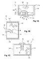
- FIG. 1A to 1C a mold 10 according to a first embodiment of the invention.
- This mold is a mold in two molding parts, jointly delimiting a molding chamber, a single molding part being visible on the Figures 1A to 1C .
- the mold 10 is a rotational molding mold for manufacturing a molded hollow body product defined by the mold.
- Part 12 shown on Figures 1A to 1C has a plurality of walls 14A-14D delimiting the molding chamber.
- the rotational molding consists in inserting plastic powder 16 into the mold and rotating the mold along at least one axis by heating it so that the powder adheres to all the walls of the mold and then becomes viscous in order to form the molded product.
- a mold wall 14A includes a vent port 18 allowing hot air in the mold chamber to escape from the mold.
- a rigid conduit 20, for example made of the same material as the mold 10 is mounted on the wall 14A so as to include a first end 21 opening into the orifice 18 and a second end 22 located inside the chamber molding.
- This rigid conduit 20 comprises at its first end a flange 24 intended to be applied against the outer face of the wall 14A.
- the collar of the rigid conduit can be fixed to the wall 14A by screwing.
- the mold also comprises a flexible conduit 26, fitted with conventional means on the second end 22 of the rigid conduit 20, with the interposition of a seal.
- the flexible conduit is made of a heat-resistant polymeric material based on an elastomer such as rubber.
- This conduit comprises an end 27 connected to the rigid conduit and an opposite free end 28. In the vicinity of the free end, is arranged a mass 30. This mass is formed by a ring placed around the flexible conduit.
- the free end of the flexible conduit is always oriented downwards, whatever the orientation of the mold.
- the powder 16 which always tends to fall vertically from the highest wall of the mold does not engage in the flexible conduit and is therefore not likely to escape the mold.
- the length of the flexible duct is chosen according to its flexibility so that the free end of the duct is able to be oriented downwards even when the wall 14A is the lower wall of the mold (case of the Figure 1A ).
- the length of the rigid duct is chosen so that the flexible duct does not come into contact with the wall of the mold even in the case of the Figure 1A .
- the mold 40 comprises, as already described, two parts of which only one is represented in the figure 2 .
- the portion comprises a plurality of walls 44A-44D delimiting a molding chamber 46.
- Plastic powder 48 is introduced into the mold to form a hollow part.
- the wall 44A comprises two vent holes 50A, 50B.
- a rigid conduit 52A, 52B located partially inside the mold, in the molding chamber, and partially outside thereof.
- Each rigid conduit passes through the wall 44A through the vent orifice to which it is connected, and is, of course, in fluid communication with the orifice.
- each rigid conduit On each rigid conduit, is also fitted a flexible conduit, respectively 54A, 54B, comprising an end connected to the rigid conduit and an opposite free end on which is arranged a mass 56A, 56B, as already described above.
- a shutter 58 with adjustable opening to limit the amount of air escaping from the mold.
- a distributor 60 that circulates the air in the mold through two inputs. Upstream of one of the inputs are means for supplying the mold with fluid under pressure, for example compressed air.
- the other of the inputs is left free so that the air can exit the mold by duct during the heating phase of the mold.
- Such a mold makes it possible to conform the product in the mold during the cooling phase. Indeed, by injecting during this phase of the compressed air by the first orifice, and by adjusting the opening of the shutter so that the outlet flow of the shutter is low, the pressure is increased to the inside the molding chamber and thus prevents the removal of the part during its cooling, since it is pressed against the walls of the mold.
- the presence of two orifices makes it possible to improve the air circulation and to create convection movements when the cold air coming from the outside of the mold meets the hot air coming from the heating of the mold.
- Cooling is therefore faster and more efficient, and thus more balanced between the polymer surface in contact with the mold and the opposite, exposed to the internal air. Balanced cooling ensures the homogeneity of the morphology of the polymer and thus leads to the reduction of warping phenomena related to the differential shrinkage.
- the shape of the mold is not limited to what has been described. It can include more than two parts.
- the vent holes may be distributed differently in the mold.
- the mold can understand more than two.
- the mold may also comprise two orifices, each being arranged in a part of the mold or on a separate wall of the same part.
- the mass can be put in place at the end of the flexible conduit by means other than those described above. It can also be of a different form from what has been described previously.
- the mold may also not include a mass, or rigid conduit, the flexible conduit being in this case directly connected to the wall of the mold.
- the flexible conduit may for example be made of a material based on silicone elastomer or polyurethane.
- the rigid conduit may be made of PTFE, or a mixture of epoxy resin and glass fiber, for example.
- shutters and distributors are also optional, as well as the feed means for the molding chamber in pressurized fluid.
Landscapes
- Engineering & Computer Science (AREA)
- Mechanical Engineering (AREA)
- Moulds For Moulding Plastics Or The Like (AREA)
Abstract
Description
La présente invention concerne un moule pour le rotomoulage de produits en matière plastique, notamment de conteneurs de collecte de déchets de grand volume, en particulier supérieur à 1000 L.The present invention relates to a mold for rotomolding plastic products, especially large volume waste collection containers, in particular greater than 1000 L.
Le rotomoulage consiste à mettre en place dans un moule une petite quantité de matériau polymère sous forme de poudre dans le but de former un objet creux. Le moule est ensuite placé dans un four et est mis en rotation selon un, et plus généralement, une pluralité d'axes. Ainsi, grâce aux mouvements de rotation du moule, on vient déposer la matière plastique en poudre sur les parois du moule. Du fait de la température de ces parois, la poudre qui vient se déposer sur les parois passe au moins partiellement à l'état visqueux à leur contact et adhère à ces parois, de façon à former un solide visqueux qui suit le contour du moule. Cette masse est ensuite refroidie pour former l'objet moulé.Rotational molding consists of placing a small amount of polymer material in powder form in a mold in order to form a hollow object. The mold is then placed in an oven and is rotated according to one, and more generally, a plurality of axes. Thus, thanks to the rotational movements of the mold, the plastic material in powder form is deposited on the walls of the mold. Because of the temperature of these walls, the powder that is deposited on the walls passes at least partially to the viscous state on their contact and adheres to these walls, so as to form a viscous solid which follows the contour of the mold. This mass is then cooled to form the molded object.
On connaît à cet effet un moule comprenant une partie fixe et une partie mobile comportant chacune des parois délimitant une chambre de moulage fermée. Cette chambre est généralement de grand volume. Au moins un orifice formant évent est ménagé dans une paroi du moule pour éviter qu'il existe une différence de pression entre l'intérieur et l'extérieur du moule, une telle différence de pression étant due notamment à la détente de l'air situé à l'intérieur du moule. De tels évents permettent également un refroidissement plus rapide du moule durant la phase de refroidissement.A mold is known for this purpose comprising a fixed part and a movable part each having walls defining a closed molding chamber. This room is usually large. At least one orifice forming a vent is formed in a wall of the mold to prevent a pressure difference between the inside and the outside of the mold, such a pressure difference being due in particular to the expansion of the air located inside the mold. Such vents also allow faster cooling of the mold during the cooling phase.
Généralement, dans l'état de la technique, on met en place, dans chacun des évents, de la paille de fer tassée, qui laisse théoriquement traverser l'air mais empêche le passage de la poudre de polymère vers l'extérieur du moule.Generally, in the state of the art, is placed in each of the vents, packed iron straw, which theoretically allows air to pass through but prevents the passage of the polymer powder to the outside of the mold.
Toutefois, cette opération de mise en place de la paille de fer dans l'évent du moule est effectuée manuellement par un opérateur. Elle présente ainsi l'inconvénient d'être difficilement répétable. En outre, un mauvais dosage de la paille de fer peut engendrer des défauts dans le produit moulé ou des dégradations de l'outillage de moulage.However, this operation of placing the iron straw in the vent of the mold is performed manually by an operator. It thus has the disadvantage of being difficult to repeat. In addition, a wrong dosage of the iron straw can cause defects in the molded product or damage to the molding tool.
Par exemple, si une quantité de paille de fer trop importante est mise en place dans le moule, une quantité d'air insuffisante s'échappe du moule et celui-ci peut être déformé du fait de la surpression y régnant. Une forme défectueuse du produit moulé peut alors résulter de cette déformation. Une quantité de paille de fer pas suffisamment importante laisse sortir trop de poudre à l'extérieur du moule ce qui est susceptible de dégrader le fonctionnement de l'outil de rotation du moule ou de former une couche thermiquement isolante sur le moule, néfaste à la formation de l'objet moulé.For example, if a too large amount of iron straw is placed in the mold, an insufficient amount of air escapes from the mold and it can be deformed due to the overpressure therein. A defective form of the molded product may then result from this deformation. A quantity of iron straw that is not large enough leaves too much powder outside the mold, which is likely to degrade the operation of the mold rotation tool or to form a thermally insulating layer on the mold, which is harmful to the mold. formation of the molded object.
On cherche donc, pour améliorer le procédé de rotomoulage, à mieux contrôler l'aération du moule, de façon à éviter au maximum et de façon répétable la sortie de poudre à l'extérieur du moule tout en laissant un passage suffisant pour l'air.In order to improve the rotational molding process, it is therefore sought to better control aeration of the mold, so as to avoid the maximum and repeatably the powder outlet outside the mold while leaving a sufficient passage for air.
A cet effet, l'invention a pour objet un moule pour le rotomoulage d'une pièce en matière plastique, comprenant une pluralité de parois délimitant une chambre de moulage fermée, au moins une paroi du moule comportant un orifice apte à évacuer vers l'extérieur un fluide situé dans la chambre de moulage, le moule comportant également un conduit flexible situé au moins partiellement dans la chambre de moulage, en communication de fluide avec l'orifice, le conduit comprenant une extrémité liée à la paroi du moule et une extrémité libre.To this end, the subject of the invention is a mold for rotomolding a plastic part, comprising a plurality of walls delimiting a closed molding chamber, at least one wall of the mold having an orifice capable of discharging towards the a fluid located in the molding chamber, the mold also having a flexible conduit located at least partially in the molding chamber, in fluid communication with the orifice, the conduit comprising an end connected to the wall of the mold and an end free.
On entend par « communication de fluide » que le fluide (l'air) situé à l'intérieur du moule circule entre le conduit et l'orifice, soit que le conduit est relié directement ou indirectement à cet orifice. De même, on entend par « extrémité liée à la paroi du moule » une extrémité du conduit fixée directement ou par l'intermédiaire d'autres éléments à la paroi du moule.The term "fluid communication" is understood to mean that the fluid (air) situated inside the mold circulates between the conduit and the orifice, ie that the conduit is connected directly or indirectly to this orifice. Similarly, the term "end connected to the wall of the mold" an end of the conduit attached directly or through other elements to the wall of the mold.
De cette façon, du fait de la flexibilité du conduit et sous l'effet de la gravité, l'extrémité libre du conduit est toujours orientée vers le bas, quelle que soit l'orientation du moule. La poudre doit ainsi effectuer un trajet vertical et vers le haut pour entrer dans le conduit. Par exemple, lorsque la paroi comprenant les orifices forme la paroi inférieure du moule, le conduit flexible forme un demi-cercle, alors que lorsque cette paroi forme la paroi supérieure, il est droit et vertical avec son extrémité libre vers le bas.In this way, because of the flexibility of the duct and under the effect of gravity, the free end of the duct is always oriented downwards, regardless of the orientation of the mold. The powder must thus make a vertical and upward path to enter the conduit. For example, when the wall comprising the orifices forms the bottom wall of the mold, the flexible duct forms a semicircle, whereas when this wall forms the upper wall, it is straight and vertical with its free end downwards.
Cela rend donc difficile l'entrée de la poudre dans le conduit, au vu de l'effet de la gravité, et par conséquent la poudre ne peut pas s'échapper du moule.This therefore makes it difficult for the powder to enter the conduit, in view of the effect of gravity, and therefore the powder can not escape from the mold.
Ainsi, on évite tout endommagement du moule, de l'outil de rotation ou du four. On sauvegarde donc les outils de moulage et on évite de devoir prévoir une maintenance fréquente de ceux-ci.Thus, it avoids any damage to the mold, the rotating tool or the oven. So we save the molding tools and avoids having to provide for frequent maintenance thereof.
En outre, puisque toute la poudre reste dans le moule, on s'assure que chaque conteneur est formé avec la même quantité de matière. On peut ainsi faire des économies de matière, puisqu'il n'est pas nécessaire de placer un surplus de poudre dans le moule et/ou limiter le taux de conteneur mis au rebut, du fait d'une épaisseur de paroi insuffisante.In addition, since all the powder remains in the mold, it is ensured that each container is formed with the same amount of material. It can thus save material, since it is not necessary to place a surplus of powder in the mold and / or limit the rate of container discarded due to insufficient wall thickness.
De plus, on évite l'utilisation de paille de fer consommable et on économise donc de la matière. On diminue également le temps de cycle puisque l'on évite l'étape de mise en place de la paille de fer dans l'orifice. Le moule selon l'invention permet donc d'économiser des coûts de fabrication.In addition, it avoids the use of consumable iron straw and thus saves material. The cycle time is also reduced since it avoids the step of placing the iron straw in the orifice. The mold according to the invention thus saves manufacturing costs.
On notera également que, comme la poudre n'est pas susceptible de s'échapper du moule, le diamètre des orifices peut être modifié, notamment agrandi, pour augmenter l'efficacité du refroidissement.It should also be noted that, since the powder is not likely to escape from the mold, the diameter of the orifices may be modified, in particular enlarged, for increase the cooling efficiency.
Le moule selon l'invention peut également comprendre l'une ou plusieurs des caractéristiques suivantes :
- une masse est ménagée sur le conduit flexible, au voisinage de son extrémité libre. Cela permet d'accentuer encore la courbure du conduit flexible lorsque celui-ci est soumis à la gravité et de diminuer encore la probabilité que la poudre pénètre dans ce conduit,
- un conduit rigide est ménagé dans le moule, un tel conduit étant en communication de fluide avec l'orifice et solidaire de la paroi du moule, le conduit flexible étant raccordé au conduit rigide. Un tel conduit rigide permet d'éloigner de la paroi du moule l'extrémité liée, et de ce fait l'extrémité libre, du conduit flexible. On évite ainsi que le conduit flexible n'entre en contact en cours de moulage avec une paroi du moule et ne dégrade l'objet moulé,
- le moule comprend au moins deux orifices, un conduit flexible, et éventuellement un conduit rigide, étant en communication de fluide avec chacun des orifices. De cette façon, on peut créer une circulation d'air plus importante dans la chambre de moulage, de l'air entrant dans la chambre grâce à l'un des orifices puis sortant de celle-ci par l'autre orifice. Cela crée en outre un effet de convection qui permet d'accélérer encore le refroidissement de l'objet. Les orifices sont ménagés par exemple dans la même paroi du moule,
- le moule comprend un distributeur à double entrée à l'extérieur du moule, en communication de fluide avec un orifice du moule de sorte que le fluide (tel que l'air), entrant dans la chambre de moulage par cet orifice peut provenir de deux sources. Des moyens d'alimentation en fluide sous pression, tel que de l'air comprimé, de la chambre de moulage peuvent également être prévus, notamment par l'intermédiaire d'une entrée du distributeur, afin de pouvoir gérer le retrait de la pièce dans le moule. On peut en effet éviter ce retrait en plaquant grâce à l'air sous pression la matière contre les parois du moule. La pièce est ainsi conformée dans le moule. En effet, actuellement, à la fin du moulage, les pièces sont sorties du moule et replacées dans un gabarit pour conformer celle-ci dans leur forme finale, ce qui pourrait être évité grâce au moule selon l'invention. Les moyens d'alimentation peuvent être ménagés sur le moule ou être rapportés sur celui-ci en phase de refroidissement,
- un obturateur à ouverture réglable est placé à l'extérieur du moule, l'obturateur étant agencé de sorte que le fluide s'échappant du moule par l'un au moins des orifices circule dans l'obturateur. De cette façon, lors du refroidissement, on peut régler l'ouverture de l'obturateur pour gérer au mieux le retrait de la pièce.
- le conduit flexible est réalisé à base d'un matériau élastomère tel que le caoutchouc, l'élastomère silicone, ou le polyuréthane,
- le conduit rigide est réalisé à base de métal, de thermoplastique tel que le PTFE (Poly Ethylène Tétra Fluoré), ou d'un matériau composite comprenant par exemple de la résine thermodurcissable, tel que la résine époxy, renforcée de fibres,
- la masse est par exemple un anneau placé autour du conduit, au voisinage de son extrémité libre.
- La longueur du conduit flexible est supérieure à 200mm et la longueur du conduit rigide est supérieure à 10mm.
- a mass is formed on the flexible duct, near its free end. This makes it possible to further accentuate the curvature of the flexible duct when it is subjected to gravity and to further reduce the probability of the powder entering this duct,
- a rigid conduit is formed in the mold, such a conduit being in fluid communication with the orifice and integral with the wall of the mold, the flexible conduit being connected to the rigid conduit. Such a rigid conduit allows to move away from the wall of the mold the bonded end, and thus the free end, of the flexible conduit. This prevents the flexible conduit from coming into contact during molding with a wall of the mold and does not degrade the molded object,
- the mold comprises at least two orifices, a flexible conduit, and possibly a rigid conduit, being in fluid communication with each of the orifices. In this way, it is possible to create a greater air flow in the molding chamber, air entering the chamber through one of the orifices and out of the latter through the other orifice. This also creates a convection effect that further accelerates the cooling of the object. The orifices are formed for example in the same wall of the mold,
- the mold comprises a double inlet manifold outside the mold, in fluid communication with a mold orifice so that the fluid (such as air) entering the molding chamber through this orifice can come from two sources. Means for supplying pressurized fluid, such as compressed air, from the molding chamber may also be provided, in particular via an inlet of the distributor, in order to be able to manage the withdrawal of the part in the mold. This shrinkage can indeed be avoided by pressing the material against the walls of the mold by means of pressurized air. The piece is thus shaped in the mold. Indeed, currently, at the end of the molding, the parts are out of the mold and replaced in a template to form it in their final form, which could be avoided by the mold according to the invention. The supply means may be provided on the mold or be reported thereon in the phase of cooling,
- a shutter with adjustable opening is placed outside the mold, the shutter being arranged so that the fluid escaping from the mold by at least one of the orifices circulates in the shutter. In this way, during cooling, you can adjust the opening of the shutter to better manage the removal of the room.
- the flexible conduit is made of an elastomeric material such as rubber, silicone elastomer, or polyurethane,
- the rigid conduit is made of metal, thermoplastic such as PTFE (polyethylene tetra fluorinated), or a composite material comprising for example thermosetting resin, such as epoxy resin, reinforced with fibers,
- the mass is for example a ring placed around the duct, near its free end.
- The length of the flexible duct is greater than 200mm and the length of the rigid duct is greater than 10mm.
L'invention sera mieux comprise à la lecture de la description qui va suivre, donnée uniquement à titre d'exemple et faite en se référant aux dessins dans lesquels :
- la
figure 1A représente une vue en coupe d'un moule selon un mode de réalisation de l'invention, - les
figures 1B et 1C représentent le moule de lafigure 1A dans une autre position, - la
figure 2 est une vue en coupe d'un moule selon un autre mode de réalisation de l'invention.
- the
Figure 1A represents a sectional view of a mold according to one embodiment of the invention, - the
Figures 1B and 1C represent the mold of theFigure 1A in another position, - the
figure 2 is a sectional view of a mold according to another embodiment of the invention.
On a représenté sur les
Comme expliqué plus haut, le rotomoulage consiste à insérer dans le moule de la poudre 16 de matière plastique et à faire tourner le moule selon au moins un axe en le chauffant pour que la poudre adhère à toutes les parois du moule puis devienne visqueuse afin de former le produit moulé.As explained above, the rotational molding consists in inserting
Pour éviter une surpression dans le moule au cours du chauffage, une paroi 14A du moule comprend un orifice d'éventation 18 permettant à l'air chaud situé dans la chambre de moulage de s'échapper du moule.To prevent overpressure in the mold during heating, a
Un conduit rigide 20, par exemple réalisé dans le même matériau que le moule 10 est monté sur la paroi 14A de façon à comprendre une première extrémité 21 débouchant dans l'orifice 18 et une deuxième extrémité 22 située à l'intérieur de la chambre de moulage. Ce conduit rigide 20 comprend à sa première extrémité une collerette 24 destiné à s'appliquer contre la face extérieure de la paroi 14A. La collerette du conduit rigide peut être fixée à la paroi 14A par vissage.A
Le moule comprend également un conduit flexible 26, emmanché à l'aide de moyens classiques sur la deuxième extrémité 22 du conduit rigide 20, avec interposition d'un joint. Le conduit flexible est réalisé en un matériau polymère résistant à la chaleur, à base d'élastomère tel que le caoutchouc. Ce conduit comprend une extrémité 27 liée au conduit rigide et une extrémité libre 28 opposée. Au voisinage de l'extrémité libre, est agencée une masse 30. Cette masse est formée par un anneau mis en place autour du conduit flexible.The mold also comprises a
Ainsi, comme on le voit sur les différentes figures, l'extrémité libre du conduit flexible est toujours orientée vers le bas, et ce quelle que soit l'orientation du moule. Ainsi, la poudre 16, qui a toujours tendance à tomber verticalement depuis la paroi la plus haute du moule ne s'engage pas dans le conduit flexible et n'est donc pas susceptible de s'échapper du moule.Thus, as seen in the various figures, the free end of the flexible conduit is always oriented downwards, whatever the orientation of the mold. Thus, the
La longueur du conduit flexible est choisie en fonction de sa flexibilité de sorte que l'extrémité libre du conduit soit apte à se trouver orientée vers le bas même lorsque la paroi 14A est la paroi inférieure du moule (cas de la
On va maintenant décrire en référence à la
Le moule 40 comprend, comme déjà décrit, deux parties dont une seule est représentée à la
La paroi 44A comprend deux orifices 50A, 50B d'éventation. Dans chaque orifice est mis en place un conduit rigide 52A, 52B, situés partiellement à l'intérieur du moule, dans la chambre de moulage, et partiellement à l'extérieur de celui-ci. Chaque conduit rigide traverse la paroi 44A par le biais de l'orifice d'éventation auquel il est relié, et est, bien sûr, en communication de fluide avec l'orifice.The
Sur chaque conduit rigide, est également emmanché un conduit flexible, respectivement 54A, 54B, comprenant une extrémité liée au conduit rigide et une extrémité libre opposée sur laquelle est agencée une masse 56A, 56B, comme déjà décrit précédemment.On each rigid conduit, is also fitted a flexible conduit, respectively 54A, 54B, comprising an end connected to the rigid conduit and an opposite free end on which is arranged a
A l'extérieur du moule, directement en communication de fluide avec le conduit 52A, est agencé un obturateur 58 à ouverture réglable permettant de limiter la quantité d'air s'échappant du moule.Outside the mold, directly in fluid communication with the
A l'extérieur du moule, directement en communication de fluide avec le conduit 52B, est placé un distributeur 60 qui permet de faire circuler l'air dans le moule par le biais de deux entrées. En amont de l'une des entrées se trouvent des moyens d'alimentation du moule en fluide sous pression, par exemple en air comprimé.Outside the mold, directly in fluid communication with the
L'autre des entrées est laissée libre de sorte que l'air peut sortir du moule par conduit lors de la phase de chauffage du moule.The other of the inputs is left free so that the air can exit the mold by duct during the heating phase of the mold.
Un tel moule permet de conformer le produit dans le moule lors de la phase de refroidissement. En effet, en injectant lors de cette phase de l'air comprimé par le premier orifice, et en réglant l'ouverture de l'obturateur de sorte que le débit de sortie de l'obturateur soit faible, on augmente la pression à l'intérieur de la chambre de moulage et on empêche ainsi le retrait de la pièce lors de son refroidissement, puisque celle-ci se plaque contre les parois du moule.Such a mold makes it possible to conform the product in the mold during the cooling phase. Indeed, by injecting during this phase of the compressed air by the first orifice, and by adjusting the opening of the shutter so that the outlet flow of the shutter is low, the pressure is increased to the inside the molding chamber and thus prevents the removal of the part during its cooling, since it is pressed against the walls of the mold.
En outre, la présence de deux orifices permet d'améliorer la circulation de l'air et de créer des mouvements de convection lorsque l'air froid provenant de l'extérieur du moule rencontre l'air chaud issu du chauffage du moule.In addition, the presence of two orifices makes it possible to improve the air circulation and to create convection movements when the cold air coming from the outside of the mold meets the hot air coming from the heating of the mold.
Le refroidissement est donc plus rapide et plus efficace, et ainsi plus équilibré entre la surface de polymère en contact avec le moule et celle opposée, exposée à l'air interne. Le refroidissement équilibré assure l'homogénéité de la morphologie du polymère et conduit donc à la réduction des phénomènes de gauchissement liée au retrait différentiel.Cooling is therefore faster and more efficient, and thus more balanced between the polymer surface in contact with the mold and the opposite, exposed to the internal air. Balanced cooling ensures the homogeneity of the morphology of the polymer and thus leads to the reduction of warping phenomena related to the differential shrinkage.
L'invention n'est pas limitée aux modes de réalisation précédents.The invention is not limited to the previous embodiments.
Par exemple, la forme du moule n'est pas limitée à ce qui été décrit. Il peut comprendre plus de deux parties. En outre, les orifices d'éventation peuvent être répartis différemment dans le moule. Le moule peut en comprendre plus que deux. Le moule peut également comprendre deux orifices, chacun étant agencé dans une partie du moule ou sur une paroi distincte de la même partie.For example, the shape of the mold is not limited to what has been described. It can include more than two parts. In addition, the vent holes may be distributed differently in the mold. The mold can understand more than two. The mold may also comprise two orifices, each being arranged in a part of the mold or on a separate wall of the same part.
On notera également que la masse peut être mise en place à l'extrémité du conduit flexible par d'autres moyens que ceux décrits précédemment. Elle peut également être de forme distincte de ce qui a été décrit précédemment.It will also be noted that the mass can be put in place at the end of the flexible conduit by means other than those described above. It can also be of a different form from what has been described previously.
Le moule peut également ne pas comprendre de masse, ou de conduit rigide, le conduit flexible étant dans ce cas directement relié à la paroi du moule.The mold may also not include a mass, or rigid conduit, the flexible conduit being in this case directly connected to the wall of the mold.
Les matériaux des différents éléments ne sont pas non plus limités à ce qui a été décrit. Le conduit flexible peut par exemple être réalisé en un matériau à base d'élastomère silicone ou de polyuréthane. Le conduit rigide peut être réalisé en PTFE, ou en un mélange de résine époxy et de fibres de verre, par exemple.The materials of the various elements are not limited to what has been described. The flexible conduit may for example be made of a material based on silicone elastomer or polyurethane. The rigid conduit may be made of PTFE, or a mixture of epoxy resin and glass fiber, for example.
Bien entendu, les obturateurs et distributeurs sont également optionnels, ainsi que les moyens d'alimentation de la chambre de moulage en fluide sous pression.Of course, the shutters and distributors are also optional, as well as the feed means for the molding chamber in pressurized fluid.
Claims (10)
Applications Claiming Priority (1)
| Application Number | Priority Date | Filing Date | Title |
|---|---|---|---|
| FR1057283A FR2964589B1 (en) | 2010-09-13 | 2010-09-13 | MOLD WITH AN EVENT SYSTEM |
Publications (2)
| Publication Number | Publication Date |
|---|---|
| EP2428343A1 true EP2428343A1 (en) | 2012-03-14 |
| EP2428343B1 EP2428343B1 (en) | 2013-05-22 |
Family
ID=43480723
Family Applications (1)
| Application Number | Title | Priority Date | Filing Date |
|---|---|---|---|
| EP20110180958 Not-in-force EP2428343B1 (en) | 2010-09-13 | 2011-09-12 | Mould for rotational moulding provided with a venting system |
Country Status (3)
| Country | Link |
|---|---|
| EP (1) | EP2428343B1 (en) |
| ES (1) | ES2428520T3 (en) |
| FR (1) | FR2964589B1 (en) |
Citations (3)
| Publication number | Priority date | Publication date | Assignee | Title |
|---|---|---|---|---|
| DE2756384A1 (en) * | 1977-12-17 | 1979-06-28 | Ernst Reitberger | Thermoplastic hollow articles - mfd. in rotational casting moulds with vacuum and inert gas supply to mould and flanges |
| GB2308326A (en) * | 1995-12-20 | 1997-06-25 | Lin Pac Mouldings | Rotary moulding apparatus includes chamber having vent with thermally responsive closure to close and open the vent in response to mould temperature |
| EP1808280A2 (en) * | 2006-01-16 | 2007-07-18 | Persico S.p.A. | Die with controlled breather for rotational pressing |
-
2010
- 2010-09-13 FR FR1057283A patent/FR2964589B1/en not_active Expired - Fee Related
-
2011
- 2011-09-12 EP EP20110180958 patent/EP2428343B1/en not_active Not-in-force
- 2011-09-12 ES ES11180958T patent/ES2428520T3/en active Active
Patent Citations (3)
| Publication number | Priority date | Publication date | Assignee | Title |
|---|---|---|---|---|
| DE2756384A1 (en) * | 1977-12-17 | 1979-06-28 | Ernst Reitberger | Thermoplastic hollow articles - mfd. in rotational casting moulds with vacuum and inert gas supply to mould and flanges |
| GB2308326A (en) * | 1995-12-20 | 1997-06-25 | Lin Pac Mouldings | Rotary moulding apparatus includes chamber having vent with thermally responsive closure to close and open the vent in response to mould temperature |
| EP1808280A2 (en) * | 2006-01-16 | 2007-07-18 | Persico S.p.A. | Die with controlled breather for rotational pressing |
Also Published As
| Publication number | Publication date |
|---|---|
| ES2428520T3 (en) | 2013-11-08 |
| EP2428343B1 (en) | 2013-05-22 |
| FR2964589A1 (en) | 2012-03-16 |
| FR2964589B1 (en) | 2012-10-12 |
Similar Documents
| Publication | Publication Date | Title |
|---|---|---|
| US9352497B2 (en) | Mould for the rotational moulding of plastic materials | |
| EP3083190B1 (en) | Moulding device including a one-piece mould bottom including a heat-exchange cavity matching a moulding surface | |
| FR2683728A1 (en) | Method and apparatus for forming an outer coating without a join (seam) over a golf ball and this ball | |
| FR2524381A1 (en) | PRESSING OF REINFORCED THERMOSETTING POLYMER ARTICLES | |
| FR3008641A1 (en) | METHOD FOR ATTACHING AN ACCESSORY TO THE WALL OF A TANK | |
| FR2548951A1 (en) | PROCESS AND DEVICE FOR MANUFACTURING THIN WALL BODIES FROM PLASTIC MATERIAL | |
| FR3101272A3 (en) | Multilayer Structure PVC Ball and PVC Ball Making Device | |
| EP2428343B1 (en) | Mould for rotational moulding provided with a venting system | |
| EP2647479A1 (en) | Method for injection moulding of a foam plastic material | |
| US6409954B1 (en) | Method of making a rotary molded plastic member with variable wall thickness | |
| EP2244872B1 (en) | Mould device for rotational moulding machine and rotational moulding machine including same | |
| FR2850899A1 (en) | Manufacture of hollow bodies by extrusion and blowing a thermoplastic resin uses blowing mould and mobile die with channel for pressure fluid | |
| EP0968064B1 (en) | Method and installation for low pressure die casting in a mould with ceramic casting die | |
| EP1922205A1 (en) | Mold-carrier unit for thermoformable container blowing machine | |
| FR3081748A1 (en) | METHOD FOR MANUFACTURING A MOLD FOR MAKING A LAMINATED STRUCTURE, RESULTING MOLD AND METHOD FOR MANUFACTURING A LAMINATED STRUCTURE | |
| FR2986983A1 (en) | Core making device used to cast by gravity, comprises firing head, core box, and enclosure comprising upstream opening that distributes powder compound in cavities of box, and powder compound distributor member having volume with channels | |
| EP2682257A1 (en) | Method and device for making parts in composite material by RTM | |
| FR2576544A1 (en) | Process for manufacturing hollow articles by moulding, device for the implementation of this process and products obtained. | |
| EP3184201B1 (en) | Foundry core-making device operating by gravity | |
| EP2930042A1 (en) | Tank with ventilation channel with cover | |
| FR3075684A1 (en) | MONOBLOC MOLD FOUNDATION WITH OPTIMIZED FLUIDIC CIRCULATION | |
| FR2903335A1 (en) | Concrete shaft manufacture device, has structure with housing in which core is positioned, bottom positioned on core`s upper end, enclosure positioned in or outside housing, and unit that removes support ring and shaft outside housing | |
| EP3763503B1 (en) | Mould for injection of expanded polystyrene for forming a hollow element | |
| FR2649916A1 (en) | Universal mould with adaptable moulding surfaces for moulding plastic, ceramic or other materials | |
| WO2023131587A1 (en) | Overmoulding an element made from thermosetting polymer |
Legal Events
| Date | Code | Title | Description |
|---|---|---|---|
| AK | Designated contracting states |
Kind code of ref document: A1 Designated state(s): AL AT BE BG CH CY CZ DE DK EE ES FI FR GB GR HR HU IE IS IT LI LT LU LV MC MK MT NL NO PL PT RO RS SE SI SK SM TR |
|
| AX | Request for extension of the european patent |
Extension state: BA ME |
|
| PUAI | Public reference made under article 153(3) epc to a published international application that has entered the european phase |
Free format text: ORIGINAL CODE: 0009012 |
|
| 17P | Request for examination filed |
Effective date: 20120914 |
|
| GRAP | Despatch of communication of intention to grant a patent |
Free format text: ORIGINAL CODE: EPIDOSNIGR1 |
|
| GRAS | Grant fee paid |
Free format text: ORIGINAL CODE: EPIDOSNIGR3 |
|
| GRAA | (expected) grant |
Free format text: ORIGINAL CODE: 0009210 |
|
| AK | Designated contracting states |
Kind code of ref document: B1 Designated state(s): AL AT BE BG CH CY CZ DE DK EE ES FI FR GB GR HR HU IE IS IT LI LT LU LV MC MK MT NL NO PL PT RO RS SE SI SK SM TR |
|
| REG | Reference to a national code |
Ref country code: GB Ref legal event code: FG4D Free format text: NOT ENGLISH |
|
| REG | Reference to a national code |
Ref country code: CH Ref legal event code: EP |
|
| REG | Reference to a national code |
Ref country code: AT Ref legal event code: REF Ref document number: 612969 Country of ref document: AT Kind code of ref document: T Effective date: 20130615 |
|
| REG | Reference to a national code |
Ref country code: IE Ref legal event code: FG4D Free format text: LANGUAGE OF EP DOCUMENT: FRENCH |
|
| REG | Reference to a national code |
Ref country code: DE Ref legal event code: R096 Ref document number: 602011001723 Country of ref document: DE Effective date: 20130718 |
|
| REG | Reference to a national code |
Ref country code: AT Ref legal event code: MK05 Ref document number: 612969 Country of ref document: AT Kind code of ref document: T Effective date: 20130522 |
|
| REG | Reference to a national code |
Ref country code: LT Ref legal event code: MG4D |
|
| PG25 | Lapsed in a contracting state [announced via postgrant information from national office to epo] |
Ref country code: NO Free format text: LAPSE BECAUSE OF FAILURE TO SUBMIT A TRANSLATION OF THE DESCRIPTION OR TO PAY THE FEE WITHIN THE PRESCRIBED TIME-LIMIT Effective date: 20130822 Ref country code: FI Free format text: LAPSE BECAUSE OF FAILURE TO SUBMIT A TRANSLATION OF THE DESCRIPTION OR TO PAY THE FEE WITHIN THE PRESCRIBED TIME-LIMIT Effective date: 20130522 Ref country code: AT Free format text: LAPSE BECAUSE OF FAILURE TO SUBMIT A TRANSLATION OF THE DESCRIPTION OR TO PAY THE FEE WITHIN THE PRESCRIBED TIME-LIMIT Effective date: 20130522 Ref country code: SE Free format text: LAPSE BECAUSE OF FAILURE TO SUBMIT A TRANSLATION OF THE DESCRIPTION OR TO PAY THE FEE WITHIN THE PRESCRIBED TIME-LIMIT Effective date: 20130522 Ref country code: SI Free format text: LAPSE BECAUSE OF FAILURE TO SUBMIT A TRANSLATION OF THE DESCRIPTION OR TO PAY THE FEE WITHIN THE PRESCRIBED TIME-LIMIT Effective date: 20130522 Ref country code: GR Free format text: LAPSE BECAUSE OF FAILURE TO SUBMIT A TRANSLATION OF THE DESCRIPTION OR TO PAY THE FEE WITHIN THE PRESCRIBED TIME-LIMIT Effective date: 20130823 Ref country code: LT Free format text: LAPSE BECAUSE OF FAILURE TO SUBMIT A TRANSLATION OF THE DESCRIPTION OR TO PAY THE FEE WITHIN THE PRESCRIBED TIME-LIMIT Effective date: 20130522 Ref country code: PT Free format text: LAPSE BECAUSE OF FAILURE TO SUBMIT A TRANSLATION OF THE DESCRIPTION OR TO PAY THE FEE WITHIN THE PRESCRIBED TIME-LIMIT Effective date: 20130923 |
|
| REG | Reference to a national code |
Ref country code: NL Ref legal event code: VDEP Effective date: 20130522 |
|
| REG | Reference to a national code |
Ref country code: ES Ref legal event code: FG2A Ref document number: 2428520 Country of ref document: ES Kind code of ref document: T3 Effective date: 20131108 |
|
| PG25 | Lapsed in a contracting state [announced via postgrant information from national office to epo] |
Ref country code: BG Free format text: LAPSE BECAUSE OF FAILURE TO SUBMIT A TRANSLATION OF THE DESCRIPTION OR TO PAY THE FEE WITHIN THE PRESCRIBED TIME-LIMIT Effective date: 20130822 Ref country code: RS Free format text: LAPSE BECAUSE OF FAILURE TO SUBMIT A TRANSLATION OF THE DESCRIPTION OR TO PAY THE FEE WITHIN THE PRESCRIBED TIME-LIMIT Effective date: 20130522 Ref country code: PL Free format text: LAPSE BECAUSE OF FAILURE TO SUBMIT A TRANSLATION OF THE DESCRIPTION OR TO PAY THE FEE WITHIN THE PRESCRIBED TIME-LIMIT Effective date: 20130522 Ref country code: HR Free format text: LAPSE BECAUSE OF FAILURE TO SUBMIT A TRANSLATION OF THE DESCRIPTION OR TO PAY THE FEE WITHIN THE PRESCRIBED TIME-LIMIT Effective date: 20130522 |
|
| PG25 | Lapsed in a contracting state [announced via postgrant information from national office to epo] |
Ref country code: LV Free format text: LAPSE BECAUSE OF FAILURE TO SUBMIT A TRANSLATION OF THE DESCRIPTION OR TO PAY THE FEE WITHIN THE PRESCRIBED TIME-LIMIT Effective date: 20130522 |
|
| PG25 | Lapsed in a contracting state [announced via postgrant information from national office to epo] |
Ref country code: CZ Free format text: LAPSE BECAUSE OF FAILURE TO SUBMIT A TRANSLATION OF THE DESCRIPTION OR TO PAY THE FEE WITHIN THE PRESCRIBED TIME-LIMIT Effective date: 20130522 Ref country code: DK Free format text: LAPSE BECAUSE OF FAILURE TO SUBMIT A TRANSLATION OF THE DESCRIPTION OR TO PAY THE FEE WITHIN THE PRESCRIBED TIME-LIMIT Effective date: 20130522 Ref country code: EE Free format text: LAPSE BECAUSE OF FAILURE TO SUBMIT A TRANSLATION OF THE DESCRIPTION OR TO PAY THE FEE WITHIN THE PRESCRIBED TIME-LIMIT Effective date: 20130522 Ref country code: SK Free format text: LAPSE BECAUSE OF FAILURE TO SUBMIT A TRANSLATION OF THE DESCRIPTION OR TO PAY THE FEE WITHIN THE PRESCRIBED TIME-LIMIT Effective date: 20130522 |
|
| PG25 | Lapsed in a contracting state [announced via postgrant information from national office to epo] |
Ref country code: RO Free format text: LAPSE BECAUSE OF FAILURE TO SUBMIT A TRANSLATION OF THE DESCRIPTION OR TO PAY THE FEE WITHIN THE PRESCRIBED TIME-LIMIT Effective date: 20130522 Ref country code: NL Free format text: LAPSE BECAUSE OF FAILURE TO SUBMIT A TRANSLATION OF THE DESCRIPTION OR TO PAY THE FEE WITHIN THE PRESCRIBED TIME-LIMIT Effective date: 20130522 |
|
| PLBE | No opposition filed within time limit |
Free format text: ORIGINAL CODE: 0009261 |
|
| STAA | Information on the status of an ep patent application or granted ep patent |
Free format text: STATUS: NO OPPOSITION FILED WITHIN TIME LIMIT |
|
| BERE | Be: lapsed |
Owner name: CIE PLASTIC OMNIUM Effective date: 20130930 |
|
| 26N | No opposition filed |
Effective date: 20140225 |
|
| PG25 | Lapsed in a contracting state [announced via postgrant information from national office to epo] |
Ref country code: MC Free format text: LAPSE BECAUSE OF FAILURE TO SUBMIT A TRANSLATION OF THE DESCRIPTION OR TO PAY THE FEE WITHIN THE PRESCRIBED TIME-LIMIT Effective date: 20130522 |
|
| REG | Reference to a national code |
Ref country code: DE Ref legal event code: R097 Ref document number: 602011001723 Country of ref document: DE Effective date: 20140225 |
|
| REG | Reference to a national code |
Ref country code: IE Ref legal event code: MM4A |
|
| PG25 | Lapsed in a contracting state [announced via postgrant information from national office to epo] |
Ref country code: IE Free format text: LAPSE BECAUSE OF NON-PAYMENT OF DUE FEES Effective date: 20130912 Ref country code: BE Free format text: LAPSE BECAUSE OF NON-PAYMENT OF DUE FEES Effective date: 20130930 |
|
| REG | Reference to a national code |
Ref country code: CH Ref legal event code: PL |
|
| PG25 | Lapsed in a contracting state [announced via postgrant information from national office to epo] |
Ref country code: SM Free format text: LAPSE BECAUSE OF FAILURE TO SUBMIT A TRANSLATION OF THE DESCRIPTION OR TO PAY THE FEE WITHIN THE PRESCRIBED TIME-LIMIT Effective date: 20130522 |
|
| PG25 | Lapsed in a contracting state [announced via postgrant information from national office to epo] |
Ref country code: TR Free format text: LAPSE BECAUSE OF FAILURE TO SUBMIT A TRANSLATION OF THE DESCRIPTION OR TO PAY THE FEE WITHIN THE PRESCRIBED TIME-LIMIT Effective date: 20130522 Ref country code: CY Free format text: LAPSE BECAUSE OF FAILURE TO SUBMIT A TRANSLATION OF THE DESCRIPTION OR TO PAY THE FEE WITHIN THE PRESCRIBED TIME-LIMIT Effective date: 20130522 Ref country code: MT Free format text: LAPSE BECAUSE OF FAILURE TO SUBMIT A TRANSLATION OF THE DESCRIPTION OR TO PAY THE FEE WITHIN THE PRESCRIBED TIME-LIMIT Effective date: 20130522 |
|
| PG25 | Lapsed in a contracting state [announced via postgrant information from national office to epo] |
Ref country code: LI Free format text: LAPSE BECAUSE OF NON-PAYMENT OF DUE FEES Effective date: 20140930 Ref country code: CH Free format text: LAPSE BECAUSE OF NON-PAYMENT OF DUE FEES Effective date: 20140930 Ref country code: HU Free format text: LAPSE BECAUSE OF FAILURE TO SUBMIT A TRANSLATION OF THE DESCRIPTION OR TO PAY THE FEE WITHIN THE PRESCRIBED TIME-LIMIT; INVALID AB INITIO Effective date: 20110912 Ref country code: LU Free format text: LAPSE BECAUSE OF NON-PAYMENT OF DUE FEES Effective date: 20130912 Ref country code: MK Free format text: LAPSE BECAUSE OF FAILURE TO SUBMIT A TRANSLATION OF THE DESCRIPTION OR TO PAY THE FEE WITHIN THE PRESCRIBED TIME-LIMIT Effective date: 20130522 |
|
| GBPC | Gb: european patent ceased through non-payment of renewal fee |
Effective date: 20150912 |
|
| PG25 | Lapsed in a contracting state [announced via postgrant information from national office to epo] |
Ref country code: IS Free format text: LAPSE BECAUSE OF FAILURE TO SUBMIT A TRANSLATION OF THE DESCRIPTION OR TO PAY THE FEE WITHIN THE PRESCRIBED TIME-LIMIT Effective date: 20130522 |
|
| PG25 | Lapsed in a contracting state [announced via postgrant information from national office to epo] |
Ref country code: GB Free format text: LAPSE BECAUSE OF NON-PAYMENT OF DUE FEES Effective date: 20150912 |
|
| REG | Reference to a national code |
Ref country code: FR Ref legal event code: PLFP Year of fee payment: 6 |
|
| REG | Reference to a national code |
Ref country code: FR Ref legal event code: PLFP Year of fee payment: 7 |
|
| REG | Reference to a national code |
Ref country code: FR Ref legal event code: PLFP Year of fee payment: 8 |
|
| PG25 | Lapsed in a contracting state [announced via postgrant information from national office to epo] |
Ref country code: AL Free format text: LAPSE BECAUSE OF FAILURE TO SUBMIT A TRANSLATION OF THE DESCRIPTION OR TO PAY THE FEE WITHIN THE PRESCRIBED TIME-LIMIT Effective date: 20130522 |
|
| REG | Reference to a national code |
Ref country code: ES Ref legal event code: PC2A Owner name: PLASTIC OMNIUM SYSTEMES URBAINS Effective date: 20190104 |
|
| REG | Reference to a national code |
Ref country code: DE Ref legal event code: R082 Ref document number: 602011001723 Country of ref document: DE Representative=s name: MAIWALD PATENTANWALTS- UND RECHTSANWALTSGESELL, DE Ref country code: DE Ref legal event code: R081 Ref document number: 602011001723 Country of ref document: DE Owner name: PLASTIC OMNIUM SYSTEMES URBAINS, FR Free format text: FORMER OWNER: COMPAGNIE PLASTIC OMNIUM, LYON, FR |
|
| PGFP | Annual fee paid to national office [announced via postgrant information from national office to epo] |
Ref country code: IT Payment date: 20190925 Year of fee payment: 9 Ref country code: FR Payment date: 20190927 Year of fee payment: 9 Ref country code: DE Payment date: 20190918 Year of fee payment: 9 |
|
| PGFP | Annual fee paid to national office [announced via postgrant information from national office to epo] |
Ref country code: ES Payment date: 20191022 Year of fee payment: 9 |
|
| REG | Reference to a national code |
Ref country code: DE Ref legal event code: R119 Ref document number: 602011001723 Country of ref document: DE |
|
| PG25 | Lapsed in a contracting state [announced via postgrant information from national office to epo] |
Ref country code: DE Free format text: LAPSE BECAUSE OF NON-PAYMENT OF DUE FEES Effective date: 20210401 Ref country code: FR Free format text: LAPSE BECAUSE OF NON-PAYMENT OF DUE FEES Effective date: 20200930 |
|
| REG | Reference to a national code |
Ref country code: ES Ref legal event code: FD2A Effective date: 20220117 |
|
| PG25 | Lapsed in a contracting state [announced via postgrant information from national office to epo] |
Ref country code: IT Free format text: LAPSE BECAUSE OF NON-PAYMENT OF DUE FEES Effective date: 20200912 |
|
| PG25 | Lapsed in a contracting state [announced via postgrant information from national office to epo] |
Ref country code: ES Free format text: LAPSE BECAUSE OF NON-PAYMENT OF DUE FEES Effective date: 20200913 |