EP2428261A2 - Filteranordnung für Hydraulikmedien, insbesondere Öl - Google Patents
Filteranordnung für Hydraulikmedien, insbesondere Öl Download PDFInfo
- Publication number
- EP2428261A2 EP2428261A2 EP11178214A EP11178214A EP2428261A2 EP 2428261 A2 EP2428261 A2 EP 2428261A2 EP 11178214 A EP11178214 A EP 11178214A EP 11178214 A EP11178214 A EP 11178214A EP 2428261 A2 EP2428261 A2 EP 2428261A2
- Authority
- EP
- European Patent Office
- Prior art keywords
- housing
- filter
- closure part
- screw
- closure
- Prior art date
- Legal status (The legal status is an assumption and is not a legal conclusion. Google has not performed a legal analysis and makes no representation as to the accuracy of the status listed.)
- Granted
Links
- 230000002093 peripheral effect Effects 0.000 claims description 4
- 230000013011 mating Effects 0.000 claims 1
- 238000007789 sealing Methods 0.000 description 3
- 230000004888 barrier function Effects 0.000 description 1
- 230000000903 blocking effect Effects 0.000 description 1
- 239000000356 contaminant Substances 0.000 description 1
- 230000007774 longterm Effects 0.000 description 1
- 238000000034 method Methods 0.000 description 1
- 230000000717 retained effect Effects 0.000 description 1
Images

Classifications
-
- B—PERFORMING OPERATIONS; TRANSPORTING
- B01—PHYSICAL OR CHEMICAL PROCESSES OR APPARATUS IN GENERAL
- B01D—SEPARATION
- B01D35/00—Filtering devices having features not specifically covered by groups B01D24/00 - B01D33/00, or for applications not specifically covered by groups B01D24/00 - B01D33/00; Auxiliary devices for filtration; Filter housing constructions
- B01D35/16—Cleaning-out devices, e.g. for removing the cake from the filter casing or for evacuating the last remnants of liquid
-
- B—PERFORMING OPERATIONS; TRANSPORTING
- B01—PHYSICAL OR CHEMICAL PROCESSES OR APPARATUS IN GENERAL
- B01D—SEPARATION
- B01D2201/00—Details relating to filtering apparatus
- B01D2201/24—Tools used for the removal of filters
-
- B—PERFORMING OPERATIONS; TRANSPORTING
- B01—PHYSICAL OR CHEMICAL PROCESSES OR APPARATUS IN GENERAL
- B01D—SEPARATION
- B01D2201/00—Details relating to filtering apparatus
- B01D2201/40—Special measures for connecting different parts of the filter
- B01D2201/4046—Means for avoiding false mounting of different parts
-
- B—PERFORMING OPERATIONS; TRANSPORTING
- B01—PHYSICAL OR CHEMICAL PROCESSES OR APPARATUS IN GENERAL
- B01D—SEPARATION
- B01D2201/00—Details relating to filtering apparatus
- B01D2201/40—Special measures for connecting different parts of the filter
- B01D2201/4092—Threaded sections, e.g. screw
Definitions
- the invention relates to a filter assembly for hydraulic media, in particular oil, with filter housing and arranged therein filter body and housing-side drain opening with screw cap.
- the screw closure part is held in and near the desired position by self-locking.
- the invention is based on the general idea, drain opening and screw closure part form such that a sufficient barrier is already reached before the screw cap reaches its gentendlage. According to the invention, such a layer can be held permanently by self-locking. By the tactile or audible locking can then be ensured that a sufficiently secured by self-locking situation has actually been achieved.
- the latching thus mainly serves only to indicate a long-term safe shut-off. On the other hand, the latching has only a minor importance in connection with securing the shut-off.
- the closure part may have a closure body insertable against frictional resistance in a housing-side drain hole and a threaded body cooperating with a housing-side threaded portion.
- the closure body takes over the fixation of the closed position by self-locking in cooperation with the housing-side drain hole.
- a preferred embodiment of the invention may be provided to arrange at the farther from the interior of the filter housing end of the closure body on the closure part openings, which communicate with a hose connection of the fferverBankerss. In this way, the oil to be drained safely into a collection container.
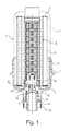
- the filter arrangement according to the invention has a housing 1 which consists, for example, of a top part 1 'and a bottom part 1 "not shown in detail. ⁇ br/> Within the housing 1 is arranged a filter body 2 which has a filter medium 4 arranged between two end disks 3.
- the filter medium 4 is generally star-shaped in plan view of the end plates 3 in order to provide the largest possible filter effective area.
- the filter body 2 connects tightly to pipe sockets, which are arranged in the upper and lower part of the housing 1.
- the filter medium 4 divides within the housing a raw space 5 and a clean room 6 from each other.
- the crude space 5 is supplied via a, for example, in the upper housing part 1 'arranged inlet (not shown) contaminated oil, the contaminants are retained during the passage of the oil through the filter medium 4, so that from the clean room 6 in the example shown also in the upper housing part 1' arranged outlet purified oil can be removed.
- an oil drain arrangement 7 is provided.
- This comprises a screw closure part 8, which has a closing body 9, which can be inserted into a correspondingly adapted section of the housing-side discharge opening.
- a sealing ring 10 which is formed as a 0-ring and arranged in a circumferential groove 9 of the closure body.
- This external threaded part 11 has a substantially tubular design and can be connected at its lower end to a hose (not shown) has a larger outer diameter compared to the closure body 9, such that an annular step is formed in the transitional area between the closure body 9 and the externally threaded part 11.
- This annular step is penetrated by openings 12 which correspond to the tubular interior of the externally threaded part 11 and thus to the external thread part 11, if applicable
- the closure body 9 is pulled out of the associated portion of the housing-side drain opening by corresponding screw adjustment of the externally threaded part 11, the interior of the housing 1 becomes over the openings n 12 with the tubular interior of the closure body 9 and thus connected to the hose, so that the existing oil in the housing 1 can run off.
- a handwheel-like handle 13 is arranged for its actuation, which is provided with latching hooks 14 which cooperate with housing-side counter-latching elements and perform a sensible or audible latching stroke when the screw-type closure member 8 reaches a plug-in position blocking the housing-side discharge opening with its closure body 9 ,
- the latching stroke of the latching hook 14 essentially serves only as a signal that the discharge opening is closed.
- the locking action is of minor importance, because the friction caused by the sealing ring 10 within the discharge opening causes the screw closure part 8 is fixed in its respective rotational position by self-locking.
- the screw closure part Since a shut-off of the discharge opening is already given before the male threaded part 11 of the closure body 9 has reached an end position within the housing-side threaded portion, the screw closure part does not need to be "tightened". Accordingly, the screw cap 8 can be operated later with opening of the discharge port with little manual force.
- Fig. 2 the screw closure part 8 is shown enlarged in perspective.
- the closure body 9 with the sealing ring 10 shown cut is formed to form an annular step in the external thread part 11 on the lower end in the drawing as a hose connection 15 is formed.
- the openings 12 are arranged, which communicate with the tubular interior of the external thread part 11.
- the handle 13 has a corrugated peripheral surface which is integrally connected to the latching hooks 14, wherein between the flanks of the latching hooks 14 and the adjacent peripheral surface of the handle 13 each slots 16 are formed, such that the latching hooks 14 only via narrow webs with the peripheral surface the handle 13 are connected. These webs are elastically twisted when the latching hooks 14 execute in the direction of arrow P.
Landscapes
- Chemical & Material Sciences (AREA)
- Chemical Kinetics & Catalysis (AREA)
- Lubrication Details And Ventilation Of Internal Combustion Engines (AREA)
- Filtration Of Liquid (AREA)
Abstract
Description
- Die Erfindung bezieht sich auf eine Filteranordnung für Hydraulikmedien, insbesondere Öl, mit Filtergehäuse sowie darin angeordnetem Filterkörper und gehäuseseitiger Ablassöffnung mit Schraubverschlussteil.
- Derartige Filteranordnungen sind allgemein bekannt. Beim Wechsel des Filterkörpers muss jeweils ein im Filtergehäuse verbleibender Ölrest abgelassen werden. Um dies zu ermöglichen, ist am Filtergehäuse eine Ablassöffnung vorgesehen, die üblicherweise mit einem Schraubelement verschlossen wird. Damit dieses beim normalen Filterbetrieb in seiner Schließlage verbleibt, muss es in der Regel mit hinreichendem Drehmoment in seine Schließlage gedreht werden. Dies ist ein vergleichsweise aufwändiger Prozess. Im Übrigen besteht die Gefahr, dass das Schraubverschlussteil mit überhöhtem Drehmoment festgedreht wird, mit der Folge, dass das Verschlussteil und/oder das Filtergehäuse beschädigt werden können.
- Deshalb ist es Aufgabe der Erfindung, einen "narrensicheren" Verschluss für die Ablassöffnung des Filtergehäuses zu schaffen.
- Diese Aufgabe wird erfindungsgemäß dadurch gelöst, dass das Schraubverschlussteil vor Erreichen seiner Schraubendlage im bzw. am zugeordneten gehäuseseitigen Gewinde eine absperrwirksame Position erreicht, und dass ein am Schraubverschlussteil angeordnetes Rastelement im Zusammenwirken mit einer gehäuseseitigen Gegenrast einen fühl- und/oder hörbaren Rasthub ausführt, wenn das Schraubverschlussteil eine absperrwirksame Solllage erreicht.
- Dabei ist vorzugsweise des Weiteren vorgesehen, dass das Schraubverschlussteil in und nahe der Solllage durch Selbsthemmung festgehalten wird. Die Erfindung beruht auf dem allgemeinen Gedanken, Ablassöffnung und Schraubverschlussteil derart auszubilden, dass eine hinreichende Absperrung bereits erreicht wird, bevor das Schraubverschlussteil seine Schraubendlage erreicht. Erfindungsgemäß kann eine solche Lage durch Selbsthemmung auf Dauer festgehalten werden. Durch die fühl- bzw. hörbare Verrastung kann dann sichergestellt werden, dass eine durch Selbsthemmung hinreichend gesicherte Lage tatsächlich erreicht worden ist. Erfindungsgemäß dient die Verrastung also vor allem nur zur Anzeige einer langfristig sicheren Absperrlage. Dagegen hat die Verrastbarkeit nur eine untergeordnete Bedeutung im Zusammenhang mit der Sicherung der Absperrlage.
- Gemäß einer konstruktiv bevorzugten Ausführungsform der Erfindung kann das Verschlussteil einen gegen Reibungswiderstand in eine gehäuseseitige Ablassbohrung einschiebbaren Verschlusskörper sowie einen mit einem gehäuseseitigen Gewindeabschnitt zusammenwirkenden Gewindekörper aufweisen. Hier übernimmt der Verschlusskörper im Zusammenwirken mit der gehäuseseitigen Ablassbohrung die Fixierung der Verschlusslage durch Selbsthemmung.
- Außerdem kann in bevorzugter Ausgestaltung der Erfindung vorgesehen sein, am vom Innenraum des Filtergehäuses ferneren Ende des Verschlusskörpers am Verschlussteil Öffnungen anzuordnen, die mit einem Schlauchanschluss des Schraubverschlussteiles kommunizieren. Auf diese Weise lässt sich das abzulassende Öl sicher in einen Auffangbehälter einführen.
- Im Übrigen wird hinsichtlich bevorzugter Merkmale der Erfindung auf die Ansprüche und die nachfolgende Erläuterung der Zeichnung verwiesen, anhand der eine besonders bevorzugte Ausführungsform der Erfindung näher beschrieben wird. Schutz wird nicht nur für angegebene oder dargestellte Merkmalskombinationen, sondern auch für prinzipiell beliebige Kombinationen der angegebenen oder dargestellten Einzelmerkmale beansprucht.
- In der Zeichnung zeigt:
- Fig. 1
- einen Axialschnitt einer erfindungsgemäßen Filteranordnung, wobei lediglich ein unterer Gehäuseteil mit der Ablassöffnung und dem zugeordneten Schraubverschlussteil und einem Filterkörper dargestellt ist, und
- Fig. 2
- eine perspektivische Darstellung des Schraubverschlussteiles.
- Gemäß
Fig. 1 besitzt die erfindungsgemäße Filteranordnung ein Gehäuse 1, welches beispielsweise aus einem nicht näher dargestellten Oberteil 1' und einem Unterteil 1" besteht. Innerhalb des Gehäuses 1 ist ein Filterkörper 2 angeordnet, welcher ein zwischen zwei Endscheiben 3 angeordnetes Filtermedium 4 aufweist. Das Filtermedium 4 ist in der Regel in Draufsicht auf die Endscheiben 3 sternförmig ausgebildet, um eine möglichst große filterwirksame Fläche bereitzustellen. - Mit den Endscheiben 3 schließt der Filterkörper 2 dicht an Rohrstutzen an, die im Ober- und Unterteil des Gehäuses 1 angeordnet sind. Damit teilt das Filtermedium 4 innerhalb des Gehäuses einen Rohraum 5 sowie einen Reinraum 6 voneinander ab. Dem Rohraum 5 wird über einen beispielsweise im Gehäuseoberteil 1' angeordneten Einlass (nicht dargestellt) verschmutztes Öl zugeführt, dessen Verschmutzungen beim Durchtritt des Öls durch das Filtermedium 4 zurückgehalten werden, so dass aus dem Reinraum 6 über einen im dargestellten Beispiel ebenfalls im Gehäuseoberteil 1' angeordneten Auslass gereinigtes Öl abgeführt werden kann.
- Grundsätzlich ist auch eine umgekehrte Strömungsrichtung des zu reinigenden Öls möglich, derart, dass der Rohraum innerhalb des Filterkörpers 2 und der Reinraum außerhalb des Filterkörpers 2 angeordnet sind.
- Bei einem Wechsel des Filterkörpers 2 muss ein im Gehäuse 1 verbleibender Ölrest abgelassen werden. Dazu ist eine Ölablassanordnung 7 vorgesehen. Diese umfasst ein Schraubverschlussteil 8, welches einen Verschlusskörper 9 aufweist, der sich in einen entsprechend angepassten Abschnitt der gehäuseseitigen Ablassöffnung einschieben lässt. Dabei wird der Radialspalt zwischen dem Außenumfang des Verschlusskörpers 9 und dem Innenumfang des zugeordneten Abschnittes der Ablassöffnung durch einen Dichtring 10 abgesperrt, der als 0-Ring ausgebildet und in einer Umfangsnut des Verschlusskörpers 9 angeordnet ist. An den Verschlusskörper 9 schließt sich nach unten ein Außengewindeteil 11 an, welches sich in einen Innengewindeabschnitt am Gehäuseunterteil 1" eindrehen lässt. Dieses Außengewindeteil 11 ist im Wesentlichen rohrförmig ausgebildet und lässt sich an seinem unteren Ende mit einem nicht dargestellten Schlauch verbinden. Das Außengewindeteil 11 besitzt einen im Vergleich zum Verschlusskörper 9 größeren Außendurchmesser, derart, dass im Übergangsbereich zwischen Verschlusskörper 9 und Außengewindeteil 11 eine Ringstufe gebildet wird. Diese Ringstufe wird von Öffnungen 12 durchsetzt, die mit dem rohrförmigen Innenraum des Außengewindeteiles 11 und damit mit dem gegebenenfalls am Außengewindeteil 11 angeschlossenen Schlauch kommunizieren. Wenn der Verschlusskörper 9 durch entsprechende Schraubverstellung des Außengewindeteiles 11 aus dem zugeordneten Abschnitt der gehäuseseitigen Ablassöffnung herausgezogen wird, wird der Innenraum des Gehäuses 1 über die Öffnungen 12 mit dem rohrförmigen Innenraum des Verschlusskörpers 9 und damit mit dem Schlauch verbunden, so dass der im Gehäuse 1 vorhandene Ölrest ablaufen kann.
- Am Schraubverschlussteil 8 ist zu seiner Betätigung eine handradartige Handhabe 13 angeordnet, die mit Rasthaken 14 versehen ist, welche mit gehäuseseitigen Gegenrastelementen zusammenwirken und einen fühl- bzw. hörbaren Rasthub ausführen, wenn das Schraubverschlussteil 8 mit seinem Verschlusskörper 9 eine die gehäuseseitige Ablassöffnung absperrende Einschublage erreicht. Dabei dient der Rasthub der Rasthaken 14 im Wesentlichen nur als Signal dafür, dass die Ablassöffnung verschlossen ist. Dagegen ist die Rastwirkung von untergeordneter Bedeutung, denn die vom Dichtring 10 bewirkte Reibung innerhalb der Ablassöffnung führt dazu, dass das Schraubverschlussteil 8 in seiner jeweiligen Drehlage durch Selbsthemmung fixiert wird. Da eine Absperrung der Ablassöffnung bereits gegeben ist, bevor das Außengewindeteil 11 des Verschlusskörpers 9 innerhalb des gehäuseseitigen Gewindeabschnittes eine Endlage erreicht hat, braucht das Schraubverschlussteil nicht "festgedreht" zu werden. Dementsprechend kann das Schraubverschlussteil 8 später beim Öffnen der Ablassöffnung mit geringer Handkraft betätigt werden.
- In
Fig. 2 ist das Schraubverschlussteil 8 vergrößert perspektivisch dargestellt. Der Verschlusskörper 9 mit dem geschnitten dargestellten Dichtring 10 geht unter Bildung einer Ringstufe in das Außengewindeteil 11 über dessen in der Zeichnung unteres Ende als Schlauchanschluss 15 ausgebildet ist. An der Stufe zwischen Verschlusskörper 9 und Außengewindeteil 11 sind die Öffnungen 12 angeordnet, die mit dem rohrförmigen Innenraum des Außengewindeteiles 11 kommunizieren. Die Handhabe 13 besitzt eine geriffelte Umfangsfläche, die einstückig mit den Rasthaken 14 verbunden ist, wobei zwischen den Flanken der Rasthaken 14 und der benachbarten Umfangsfläche der Handhabe 13 jeweils Schlitze 16 ausgebildet sind, derart, dass die Rasthaken 14 nur über schmale Stege mit der Umfangsfläche der Handhabe 13 verbunden sind. Diese Stege werden elastisch tordiert, wenn die Rasthaken 14 in Pfeilrichtung P ausführen.
Claims (5)
- Filteranordnung für Hydraulikmedien, insbesondere Öl, mit Filtergehäuse (1) sowie darin angeordnetem Filterkörper (2) und gehäuseseitiger Ablassöffnung mit Schraubverschlussteil (8),
dadurch gekennzeichnet,
dass das Schraubverschlussteil (8) vor Erreichen seiner Schraubendlage im bzw. am zugeordneten gehäuseseitigen Gewinde eine absperrwirksame Lage erreicht, und dass ein am Schraubverschlussteil (8) angeordnetes Rastelement (14) im Zusammenwirken mit einer gehäuseseitigen Gegenrast einen fühl- und/oder hörbaren Rasthub ausführt, wenn das Schraubverschlussteil (8) eine absperrwirksame Solllage erreicht. - Filteranordnung nach Anspruch 1,
dadurch gekennzeichnet,
dass das Schraubverschlussteil (8) im Bereich der Solllage durch Selbsthemmung festgehalten wird. - Filteranordnung nach Anspruch 2,
dadurch gekennzeichnet,
dass das Verschlussteil (8) einen gegen Reibungswiderstand in eine gehäuseseitige Ablassbohrung einschiebbaren Verschlusskörper (9) sowie einen mit einem gehäuseseitigen Gewindeabschnitt zusammenwirkenden Gewindekörper (11) aufweist. - Filteranordnung nach einem der Ansprüche 1 bis 3,
dadurch gekennzeichnet,
dass am vom Innenraum des Filtergehäuses (1) ferneren Ende des Verschlusskörpers (9) am Verschlussteil (8) Öffnungen (12) angeordnet sind, die mit einem Schlauchanschluss des Verschlussteiles (8) kommunizieren. - Filteranordnung nach einem der Ansprüche 1 bis 4,
dadurch gekennzeichnet,
dass am Schraubverschlussteil (8) eine handradartige Handhabe (13) mit beim Rasthub aus deren Umfangsfläche austretenden Rastelementen (14) angeordnet ist.
Priority Applications (1)
| Application Number | Priority Date | Filing Date | Title |
|---|---|---|---|
| PL11178214T PL2428261T3 (pl) | 2010-09-08 | 2011-08-22 | Układ filtracyjny dla mediów hydraulicznych, w szczególności oleju |
Applications Claiming Priority (1)
| Application Number | Priority Date | Filing Date | Title |
|---|---|---|---|
| DE102010040404A DE102010040404A1 (de) | 2010-09-08 | 2010-09-08 | Filteranordnung für Hydraulikmedium, insbesondere Öl |
Publications (3)
| Publication Number | Publication Date |
|---|---|
| EP2428261A2 true EP2428261A2 (de) | 2012-03-14 |
| EP2428261A3 EP2428261A3 (de) | 2014-10-29 |
| EP2428261B1 EP2428261B1 (de) | 2016-01-06 |
Family
ID=44675477
Family Applications (1)
| Application Number | Title | Priority Date | Filing Date |
|---|---|---|---|
| EP11178214.0A Not-in-force EP2428261B1 (de) | 2010-09-08 | 2011-08-22 | Filteranordnung für hydraulikmedien, insbesondere öl |
Country Status (3)
| Country | Link |
|---|---|
| EP (1) | EP2428261B1 (de) |
| DE (1) | DE102010040404A1 (de) |
| PL (1) | PL2428261T3 (de) |
Cited By (1)
| Publication number | Priority date | Publication date | Assignee | Title |
|---|---|---|---|---|
| CN116617856A (zh) * | 2023-05-24 | 2023-08-22 | 湖北中泉环保技术有限公司 | 一种过滤器滤壳的接口结构及过滤器 |
Family Cites Families (9)
| Publication number | Priority date | Publication date | Assignee | Title |
|---|---|---|---|---|
| DE1125621B (de) * | 1954-02-24 | 1962-03-15 | Antargaz Sa De Distrib De Gaz | Mit gasfoermigem Brennstoff betriebener Waermestrahler, insbesondere zur Raumheizung |
| JP3680396B2 (ja) * | 1995-12-27 | 2005-08-10 | 株式会社デンソー | エレメント交換型フィルタ |
| DE20008112U1 (de) * | 2000-05-05 | 2001-09-20 | Ing. Walter Hengst GmbH & Co. KG, 48147 Münster | Filtereinsatz mit Belüftungsöffnung |
| JP2004195437A (ja) * | 2002-12-20 | 2004-07-15 | Toyoda Spinning & Weaving Co Ltd | 流体フィルタ及びそのドレン機構、並びに流体フィルタのドレン方法 |
| DE102004031209A1 (de) * | 2004-06-28 | 2006-01-19 | Mann + Hummel Gmbh | Flüssigkeitsfilter |
| DE102004058885B4 (de) * | 2004-12-06 | 2016-12-22 | Mann + Hummel Gmbh | Füssigkeitsfilter |
| US20070034560A1 (en) * | 2005-08-09 | 2007-02-15 | Janik Leon P | Drain valve alignment system for filter assembly |
| FR2914198B1 (fr) * | 2007-03-28 | 2009-07-03 | Cummins Filtration Sarl | Ensemble de filtrage comprenant un corps, une tete, une cartouche et des moyens de retenue de la cartouche a la tete et au corps, et cartouche de filtration correspondante. |
| DE102009011941A1 (de) * | 2009-03-10 | 2010-09-23 | Polytec Automotive Gmbh & Co. Kg | Verschlussschraube für Öffnungen an Kraftfahrzeug-Motoren sowie Gehäuseeinheit eines Kraftfahrzeug-Motors |
-
2010
- 2010-09-08 DE DE102010040404A patent/DE102010040404A1/de not_active Withdrawn
-
2011
- 2011-08-22 EP EP11178214.0A patent/EP2428261B1/de not_active Not-in-force
- 2011-08-22 PL PL11178214T patent/PL2428261T3/pl unknown
Non-Patent Citations (1)
| Title |
|---|
| None |
Cited By (1)
| Publication number | Priority date | Publication date | Assignee | Title |
|---|---|---|---|---|
| CN116617856A (zh) * | 2023-05-24 | 2023-08-22 | 湖北中泉环保技术有限公司 | 一种过滤器滤壳的接口结构及过滤器 |
Also Published As
| Publication number | Publication date |
|---|---|
| EP2428261B1 (de) | 2016-01-06 |
| PL2428261T3 (pl) | 2016-06-30 |
| EP2428261A3 (de) | 2014-10-29 |
| DE102010040404A1 (de) | 2012-03-08 |
Similar Documents
| Publication | Publication Date | Title |
|---|---|---|
| EP3345670B1 (de) | Filtereinrichtung | |
| EP3213803B1 (de) | Filter-anordnung | |
| DE3100037C2 (de) | ||
| EP2252820B1 (de) | Einbauventilanordnung mit siebfilter | |
| EP2954598B1 (de) | Kabelfixierung | |
| DE2946064A1 (de) | Filtereinrichtung | |
| EP3004702B1 (de) | Kombination aus einem gehäuse und einem ventil | |
| EP3988196B1 (de) | Filterelement mit entfernungselement | |
| EP0314963A2 (de) | Kunststoffgehäuse | |
| EP3458175B1 (de) | Filtereinrichtung | |
| EP2337618A1 (de) | Filtereinrichtung | |
| DE102014114486B4 (de) | Ablaufstutzen | |
| EP2428261B1 (de) | Filteranordnung für hydraulikmedien, insbesondere öl | |
| DE102012004579B3 (de) | Filtereinrichtung | |
| DE102020123586B4 (de) | Filterelement, Filtereinrichtung, Anordnung und Montageverfahren | |
| EP2331228B1 (de) | Entleerungseinrichtung für fluidfilter | |
| EP3535039B1 (de) | Filtereinrichtung | |
| DE102004013570A1 (de) | Armaturenverschraubung mit Gewindesicherung | |
| EP1682807A1 (de) | Schnellkupplung | |
| EP3544714B1 (de) | Filterelement und fluidfilter mit drehbarem bajonettring | |
| EP2463006A1 (de) | Filtereinrichtung | |
| DE102014119410B4 (de) | Anbohrarmatur und Verfahren zum Herstellen einer Verbindung zu einer medienführenden Leitung mittels einer solchen Anbohrarmatur | |
| DE102019105884A1 (de) | Ablaufgarnitur für eine sanitäre Einrichtung | |
| DE102013203570A1 (de) | Schraubanordnung | |
| DE102007010472B4 (de) | Sanitäre Niederdruckarmatur |
Legal Events
| Date | Code | Title | Description |
|---|---|---|---|
| AK | Designated contracting states |
Kind code of ref document: A2 Designated state(s): AL AT BE BG CH CY CZ DE DK EE ES FI FR GB GR HR HU IE IS IT LI LT LU LV MC MK MT NL NO PL PT RO RS SE SI SK SM TR |
|
| AX | Request for extension of the european patent |
Extension state: BA ME |
|
| PUAI | Public reference made under article 153(3) epc to a published international application that has entered the european phase |
Free format text: ORIGINAL CODE: 0009012 |
|
| PUAL | Search report despatched |
Free format text: ORIGINAL CODE: 0009013 |
|
| AK | Designated contracting states |
Kind code of ref document: A3 Designated state(s): AL AT BE BG CH CY CZ DE DK EE ES FI FR GB GR HR HU IE IS IT LI LT LU LV MC MK MT NL NO PL PT RO RS SE SI SK SM TR |
|
| AX | Request for extension of the european patent |
Extension state: BA ME |
|
| RIC1 | Information provided on ipc code assigned before grant |
Ipc: B01D 35/16 20060101ALI20140924BHEP Ipc: B01D 29/96 20060101AFI20140924BHEP |
|
| 17P | Request for examination filed |
Effective date: 20150219 |
|
| RBV | Designated contracting states (corrected) |
Designated state(s): AL AT BE BG CH CY CZ DE DK EE ES FI FR GB GR HR HU IE IS IT LI LT LU LV MC MK MT NL NO PL PT RO RS SE SI SK SM TR |
|
| GRAP | Despatch of communication of intention to grant a patent |
Free format text: ORIGINAL CODE: EPIDOSNIGR1 |
|
| INTG | Intention to grant announced |
Effective date: 20150723 |
|
| GRAS | Grant fee paid |
Free format text: ORIGINAL CODE: EPIDOSNIGR3 |
|
| GRAA | (expected) grant |
Free format text: ORIGINAL CODE: 0009210 |
|
| AK | Designated contracting states |
Kind code of ref document: B1 Designated state(s): AL AT BE BG CH CY CZ DE DK EE ES FI FR GB GR HR HU IE IS IT LI LT LU LV MC MK MT NL NO PL PT RO RS SE SI SK SM TR |
|
| REG | Reference to a national code |
Ref country code: GB Ref legal event code: FG4D Free format text: NOT ENGLISH |
|
| REG | Reference to a national code |
Ref country code: CH Ref legal event code: EP |
|
| REG | Reference to a national code |
Ref country code: IE Ref legal event code: FG4D Free format text: LANGUAGE OF EP DOCUMENT: GERMAN |
|
| REG | Reference to a national code |
Ref country code: AT Ref legal event code: REF Ref document number: 768374 Country of ref document: AT Kind code of ref document: T Effective date: 20160215 |
|
| REG | Reference to a national code |
Ref country code: DE Ref legal event code: R096 Ref document number: 502011008614 Country of ref document: DE |
|
| REG | Reference to a national code |
Ref country code: LT Ref legal event code: MG4D |
|
| REG | Reference to a national code |
Ref country code: NL Ref legal event code: MP Effective date: 20160106 |
|
| PG25 | Lapsed in a contracting state [announced via postgrant information from national office to epo] |
Ref country code: NL Free format text: LAPSE BECAUSE OF FAILURE TO SUBMIT A TRANSLATION OF THE DESCRIPTION OR TO PAY THE FEE WITHIN THE PRESCRIBED TIME-LIMIT Effective date: 20160106 |
|
| PG25 | Lapsed in a contracting state [announced via postgrant information from national office to epo] |
Ref country code: NO Free format text: LAPSE BECAUSE OF FAILURE TO SUBMIT A TRANSLATION OF THE DESCRIPTION OR TO PAY THE FEE WITHIN THE PRESCRIBED TIME-LIMIT Effective date: 20160406 Ref country code: FI Free format text: LAPSE BECAUSE OF FAILURE TO SUBMIT A TRANSLATION OF THE DESCRIPTION OR TO PAY THE FEE WITHIN THE PRESCRIBED TIME-LIMIT Effective date: 20160106 Ref country code: GR Free format text: LAPSE BECAUSE OF FAILURE TO SUBMIT A TRANSLATION OF THE DESCRIPTION OR TO PAY THE FEE WITHIN THE PRESCRIBED TIME-LIMIT Effective date: 20160407 Ref country code: HR Free format text: LAPSE BECAUSE OF FAILURE TO SUBMIT A TRANSLATION OF THE DESCRIPTION OR TO PAY THE FEE WITHIN THE PRESCRIBED TIME-LIMIT Effective date: 20160106 Ref country code: ES Free format text: LAPSE BECAUSE OF FAILURE TO SUBMIT A TRANSLATION OF THE DESCRIPTION OR TO PAY THE FEE WITHIN THE PRESCRIBED TIME-LIMIT Effective date: 20160106 |
|
| REG | Reference to a national code |
Ref country code: FR Ref legal event code: PLFP Year of fee payment: 6 |
|
| PG25 | Lapsed in a contracting state [announced via postgrant information from national office to epo] |
Ref country code: IS Free format text: LAPSE BECAUSE OF FAILURE TO SUBMIT A TRANSLATION OF THE DESCRIPTION OR TO PAY THE FEE WITHIN THE PRESCRIBED TIME-LIMIT Effective date: 20160506 Ref country code: LT Free format text: LAPSE BECAUSE OF FAILURE TO SUBMIT A TRANSLATION OF THE DESCRIPTION OR TO PAY THE FEE WITHIN THE PRESCRIBED TIME-LIMIT Effective date: 20160106 Ref country code: PT Free format text: LAPSE BECAUSE OF FAILURE TO SUBMIT A TRANSLATION OF THE DESCRIPTION OR TO PAY THE FEE WITHIN THE PRESCRIBED TIME-LIMIT Effective date: 20160506 Ref country code: LV Free format text: LAPSE BECAUSE OF FAILURE TO SUBMIT A TRANSLATION OF THE DESCRIPTION OR TO PAY THE FEE WITHIN THE PRESCRIBED TIME-LIMIT Effective date: 20160106 Ref country code: SE Free format text: LAPSE BECAUSE OF FAILURE TO SUBMIT A TRANSLATION OF THE DESCRIPTION OR TO PAY THE FEE WITHIN THE PRESCRIBED TIME-LIMIT Effective date: 20160106 Ref country code: RS Free format text: LAPSE BECAUSE OF FAILURE TO SUBMIT A TRANSLATION OF THE DESCRIPTION OR TO PAY THE FEE WITHIN THE PRESCRIBED TIME-LIMIT Effective date: 20160106 |
|
| REG | Reference to a national code |
Ref country code: DE Ref legal event code: R097 Ref document number: 502011008614 Country of ref document: DE |
|
| PG25 | Lapsed in a contracting state [announced via postgrant information from national office to epo] |
Ref country code: DK Free format text: LAPSE BECAUSE OF FAILURE TO SUBMIT A TRANSLATION OF THE DESCRIPTION OR TO PAY THE FEE WITHIN THE PRESCRIBED TIME-LIMIT Effective date: 20160106 Ref country code: EE Free format text: LAPSE BECAUSE OF FAILURE TO SUBMIT A TRANSLATION OF THE DESCRIPTION OR TO PAY THE FEE WITHIN THE PRESCRIBED TIME-LIMIT Effective date: 20160106 |
|
| PLBE | No opposition filed within time limit |
Free format text: ORIGINAL CODE: 0009261 |
|
| STAA | Information on the status of an ep patent application or granted ep patent |
Free format text: STATUS: NO OPPOSITION FILED WITHIN TIME LIMIT |
|
| PG25 | Lapsed in a contracting state [announced via postgrant information from national office to epo] |
Ref country code: SM Free format text: LAPSE BECAUSE OF FAILURE TO SUBMIT A TRANSLATION OF THE DESCRIPTION OR TO PAY THE FEE WITHIN THE PRESCRIBED TIME-LIMIT Effective date: 20160106 Ref country code: CZ Free format text: LAPSE BECAUSE OF FAILURE TO SUBMIT A TRANSLATION OF THE DESCRIPTION OR TO PAY THE FEE WITHIN THE PRESCRIBED TIME-LIMIT Effective date: 20160106 Ref country code: SK Free format text: LAPSE BECAUSE OF FAILURE TO SUBMIT A TRANSLATION OF THE DESCRIPTION OR TO PAY THE FEE WITHIN THE PRESCRIBED TIME-LIMIT Effective date: 20160106 Ref country code: RO Free format text: LAPSE BECAUSE OF FAILURE TO SUBMIT A TRANSLATION OF THE DESCRIPTION OR TO PAY THE FEE WITHIN THE PRESCRIBED TIME-LIMIT Effective date: 20160106 |
|
| 26N | No opposition filed |
Effective date: 20161007 |
|
| PG25 | Lapsed in a contracting state [announced via postgrant information from national office to epo] |
Ref country code: BE Free format text: LAPSE BECAUSE OF NON-PAYMENT OF DUE FEES Effective date: 20160831 |
|
| PG25 | Lapsed in a contracting state [announced via postgrant information from national office to epo] |
Ref country code: SI Free format text: LAPSE BECAUSE OF FAILURE TO SUBMIT A TRANSLATION OF THE DESCRIPTION OR TO PAY THE FEE WITHIN THE PRESCRIBED TIME-LIMIT Effective date: 20160106 |
|
| PG25 | Lapsed in a contracting state [announced via postgrant information from national office to epo] |
Ref country code: MC Free format text: LAPSE BECAUSE OF FAILURE TO SUBMIT A TRANSLATION OF THE DESCRIPTION OR TO PAY THE FEE WITHIN THE PRESCRIBED TIME-LIMIT Effective date: 20160106 |
|
| REG | Reference to a national code |
Ref country code: CH Ref legal event code: PL |
|
| PG25 | Lapsed in a contracting state [announced via postgrant information from national office to epo] |
Ref country code: CH Free format text: LAPSE BECAUSE OF NON-PAYMENT OF DUE FEES Effective date: 20160831 Ref country code: LI Free format text: LAPSE BECAUSE OF NON-PAYMENT OF DUE FEES Effective date: 20160831 |
|
| REG | Reference to a national code |
Ref country code: IE Ref legal event code: MM4A |
|
| PG25 | Lapsed in a contracting state [announced via postgrant information from national office to epo] |
Ref country code: IE Free format text: LAPSE BECAUSE OF NON-PAYMENT OF DUE FEES Effective date: 20160822 |
|
| REG | Reference to a national code |
Ref country code: FR Ref legal event code: PLFP Year of fee payment: 7 |
|
| PG25 | Lapsed in a contracting state [announced via postgrant information from national office to epo] |
Ref country code: LU Free format text: LAPSE BECAUSE OF NON-PAYMENT OF DUE FEES Effective date: 20160822 |
|
| REG | Reference to a national code |
Ref country code: AT Ref legal event code: MM01 Ref document number: 768374 Country of ref document: AT Kind code of ref document: T Effective date: 20160822 |
|
| PG25 | Lapsed in a contracting state [announced via postgrant information from national office to epo] |
Ref country code: AT Free format text: LAPSE BECAUSE OF NON-PAYMENT OF DUE FEES Effective date: 20160822 |
|
| PG25 | Lapsed in a contracting state [announced via postgrant information from national office to epo] |
Ref country code: HU Free format text: LAPSE BECAUSE OF FAILURE TO SUBMIT A TRANSLATION OF THE DESCRIPTION OR TO PAY THE FEE WITHIN THE PRESCRIBED TIME-LIMIT; INVALID AB INITIO Effective date: 20110822 Ref country code: CY Free format text: LAPSE BECAUSE OF FAILURE TO SUBMIT A TRANSLATION OF THE DESCRIPTION OR TO PAY THE FEE WITHIN THE PRESCRIBED TIME-LIMIT Effective date: 20160106 |
|
| PG25 | Lapsed in a contracting state [announced via postgrant information from national office to epo] |
Ref country code: MK Free format text: LAPSE BECAUSE OF FAILURE TO SUBMIT A TRANSLATION OF THE DESCRIPTION OR TO PAY THE FEE WITHIN THE PRESCRIBED TIME-LIMIT Effective date: 20160106 Ref country code: MT Free format text: LAPSE BECAUSE OF FAILURE TO SUBMIT A TRANSLATION OF THE DESCRIPTION OR TO PAY THE FEE WITHIN THE PRESCRIBED TIME-LIMIT Effective date: 20160106 |
|
| REG | Reference to a national code |
Ref country code: FR Ref legal event code: PLFP Year of fee payment: 8 |
|
| PG25 | Lapsed in a contracting state [announced via postgrant information from national office to epo] |
Ref country code: AL Free format text: LAPSE BECAUSE OF FAILURE TO SUBMIT A TRANSLATION OF THE DESCRIPTION OR TO PAY THE FEE WITHIN THE PRESCRIBED TIME-LIMIT Effective date: 20160106 |
|
| PGFP | Annual fee paid to national office [announced via postgrant information from national office to epo] |
Ref country code: IT Payment date: 20180823 Year of fee payment: 8 Ref country code: FR Payment date: 20180829 Year of fee payment: 8 |
|
| PGFP | Annual fee paid to national office [announced via postgrant information from national office to epo] |
Ref country code: PL Payment date: 20180817 Year of fee payment: 8 Ref country code: BG Payment date: 20180822 Year of fee payment: 8 Ref country code: TR Payment date: 20180809 Year of fee payment: 8 Ref country code: GB Payment date: 20180831 Year of fee payment: 8 |
|
| PGFP | Annual fee paid to national office [announced via postgrant information from national office to epo] |
Ref country code: DE Payment date: 20191031 Year of fee payment: 9 |
|
| GBPC | Gb: european patent ceased through non-payment of renewal fee |
Effective date: 20190822 |
|
| PG25 | Lapsed in a contracting state [announced via postgrant information from national office to epo] |
Ref country code: BG Free format text: LAPSE BECAUSE OF NON-PAYMENT OF DUE FEES Effective date: 20200229 |
|
| PG25 | Lapsed in a contracting state [announced via postgrant information from national office to epo] |
Ref country code: FR Free format text: LAPSE BECAUSE OF NON-PAYMENT OF DUE FEES Effective date: 20190831 |
|
| PG25 | Lapsed in a contracting state [announced via postgrant information from national office to epo] |
Ref country code: GB Free format text: LAPSE BECAUSE OF NON-PAYMENT OF DUE FEES Effective date: 20190822 Ref country code: IT Free format text: LAPSE BECAUSE OF NON-PAYMENT OF DUE FEES Effective date: 20190822 |
|
| REG | Reference to a national code |
Ref country code: DE Ref legal event code: R119 Ref document number: 502011008614 Country of ref document: DE |
|
| PG25 | Lapsed in a contracting state [announced via postgrant information from national office to epo] |
Ref country code: DE Free format text: LAPSE BECAUSE OF NON-PAYMENT OF DUE FEES Effective date: 20210302 |
|
| PG25 | Lapsed in a contracting state [announced via postgrant information from national office to epo] |
Ref country code: PL Free format text: LAPSE BECAUSE OF NON-PAYMENT OF DUE FEES Effective date: 20190822 |
|
| PG25 | Lapsed in a contracting state [announced via postgrant information from national office to epo] |
Ref country code: TR Free format text: LAPSE BECAUSE OF NON-PAYMENT OF DUE FEES Effective date: 20190822 |