EP2427092B1 - Detachable dust container with cover for a vacuum cleaner - Google Patents
Detachable dust container with cover for a vacuum cleaner Download PDFInfo
- Publication number
- EP2427092B1 EP2427092B1 EP10772323.1A EP10772323A EP2427092B1 EP 2427092 B1 EP2427092 B1 EP 2427092B1 EP 10772323 A EP10772323 A EP 10772323A EP 2427092 B1 EP2427092 B1 EP 2427092B1
- Authority
- EP
- European Patent Office
- Prior art keywords
- cover
- receptacle
- lip seal
- dust
- lip
- Prior art date
- Legal status (The legal status is an assumption and is not a legal conclusion. Google has not performed a legal analysis and makes no representation as to the accuracy of the status listed.)
- Active
Links
Images

Classifications
-
- A—HUMAN NECESSITIES
- A47—FURNITURE; DOMESTIC ARTICLES OR APPLIANCES; COFFEE MILLS; SPICE MILLS; SUCTION CLEANERS IN GENERAL
- A47L—DOMESTIC WASHING OR CLEANING; SUCTION CLEANERS IN GENERAL
- A47L9/00—Details or accessories of suction cleaners, e.g. mechanical means for controlling the suction or for effecting pulsating action; Storing devices specially adapted to suction cleaners or parts thereof; Carrying-vehicles specially adapted for suction cleaners
- A47L9/10—Filters; Dust separators; Dust removal; Automatic exchange of filters
- A47L9/14—Bags or the like; Rigid filtering receptacles; Attachment of, or closures for, bags or receptacles
-
- A—HUMAN NECESSITIES
- A47—FURNITURE; DOMESTIC ARTICLES OR APPLIANCES; COFFEE MILLS; SPICE MILLS; SUCTION CLEANERS IN GENERAL
- A47L—DOMESTIC WASHING OR CLEANING; SUCTION CLEANERS IN GENERAL
- A47L9/00—Details or accessories of suction cleaners, e.g. mechanical means for controlling the suction or for effecting pulsating action; Storing devices specially adapted to suction cleaners or parts thereof; Carrying-vehicles specially adapted for suction cleaners
- A47L9/10—Filters; Dust separators; Dust removal; Automatic exchange of filters
- A47L9/16—Arrangement or disposition of cyclones or other devices with centrifugal action
- A47L9/1683—Dust collecting chambers; Dust collecting receptacles
-
- A—HUMAN NECESSITIES
- A47—FURNITURE; DOMESTIC ARTICLES OR APPLIANCES; COFFEE MILLS; SPICE MILLS; SUCTION CLEANERS IN GENERAL
- A47L—DOMESTIC WASHING OR CLEANING; SUCTION CLEANERS IN GENERAL
- A47L9/00—Details or accessories of suction cleaners, e.g. mechanical means for controlling the suction or for effecting pulsating action; Storing devices specially adapted to suction cleaners or parts thereof; Carrying-vehicles specially adapted for suction cleaners
- A47L9/10—Filters; Dust separators; Dust removal; Automatic exchange of filters
- A47L9/16—Arrangement or disposition of cyclones or other devices with centrifugal action
Definitions
- the receptacle should be provided with a cover.
- the lip seal may be made of resiliently compressible material, such as rubber or rubber like material.
- this object is achieved by a bagless vacuum cleaner equipped with a detachable dust container for collecting dust, as described above.
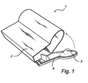
- a detachable dust container 1 for a bagless vacuum cleaner comprises a dust receptacle 2 which has a cover 3, Fig.1 .
- a cover 3 In order for the cover 3 to provide an effective sealing against the receptacle 2 it is equipped with a sealing member, a lip seal 4.
- One, two three or more longitudinal ridges 9 or grooves on the base member 5 may be provided to facilitate the attachment of the lip seal 4 in a slit in the receptacle 2 or in the cover 3, and keep the lip seal 4 in place.
- the ridges 9 may interact with one or more grooves 10a, 10b to provide a positive interlocking effect, thus keeping the lip seal 4 securely in place.
- the lip member 8 may be designed to have an extent d in the axial direction in its non-compressed state, which is larger than a largest permitted distance D between the receptacle and the cover. In various embodiments, the lip member may extend 5%, 10%, 15%, 20%, 25%, 30%, 50%, 75%, 100%, 150%, 200% or 300% beyond that distance D. Alternatively, or as a complement, a length of the lip member 8, along a face r that is to engage the opposing part, may be 5%, 10%, 15%, 20%, 25%, 30%, 50%, 75%, 100%, 150%, 200%, 300%, 400% or 500% longer than said distance D.
Description
- The present invention relates to a detachable dust container for use in a bagless vacuum cleaner, the dust container comprising a receptacle with a cover effectively sealed against the receptacle by means of a lip seal, and to a vacuum cleaner which incorporates such a dust container.
- A detachable dust container according to the preamble of
claim 1 is already known e.g. fromWO-A-02067752 - Bagless vacuum cleaners often use cyclonic separation to separate dirt and dust debris from an airflow. Bagless vacuum cleaners maintain a consistently high level of suction, even as the dust collecting container incorporated into the vacuum cleaner fills with dirt.
- A bagless vacuum cleaner is a vacuum cleaner, which instead of utilizing a flexible bag, which may be disposable, for dust collection, uses a reusable container, which may be generally rigid, as compared with a bag.
- The absence of a dust bag in the vacuum cleaner can make it difficult to dispose of the dirt and dust which is collected during the vacuuming. This can be solved by employing a removable dust collecting receptacle, which is easily disengaged from the vacuum cleaner body and emptied, and is for example shown in
US 7,201,786 . - To be able to detach a dust-filled receptacle from the vacuum cleaner body and to move with the full dust receptacle to the dust bin for discharging of its content while maintaining the hygiene of the environment and the user's hands, the receptacle should be provided with a cover.
- It is important that such a cover fits tightly on the dust receptacle, especially during operation of the vacuum cleaner, in order for air and dust not to escape from the dust collecting receptacle and the separation efficiency of the vacuum cleaner hence being reduced. Nevertheless, it is difficult to manufacture a cover for a receptacle which fits tight enough all around the cover, and the permissible variation in the manufacturing tolerances of the two parts is low.
- Conventional sealing means, such as O-rings, are used in prior art solutions, e.g. in
EP 0 743 039 andUS 2004/0074213 , for sealing of the cover against the receptacle. Using O-rings, however, it is still of particular importance to achieve a tight fit between the cover and the receptacle and the locking of the cover in closed position is also very critical, since the sealing effect of O-rings is highly dependent on the compression pressure, axially between the receptacle and the cover. - In the following, the "axial direction" is understood as a direction which is substantially normal to an opening in the receptacle, which is to be closed by the cover. The "radial direction" is understood as a direction which is substantially perpendicular to the axial direction, and extends substantially from the perimeter of the opening and towards the middle of the opening. It is understood, that the opening may have a planar or non-planar perimeter, and/or that the opening may be symmetrically or asymmetrically shaped.
- There is hence a need for a dust receptacle with a detachable cover which can be sealed against the receptacle all around the cover, and where the permissible variation in the manufacturing tolerances of the receptacle and the cover is higher and the demands on a tight fit between the two parts is lower than with prior art solutions.
- It is a general object of the present disclosure to eliminate or alleviate at least some of the disadvantages in prior art solutions.
- It is further an object to provide a detachable dust container with an effectively sealed cover for use in a bagless vacuum cleaner, and to a vacuum cleaner incorporating such a container.
- More specific objects include providing a dust container with an effectively sealed cover wherein the permissible variation in the manufacturing of the two parts is higher and the demands on a tight fit between the two parts is lower than with prior art solutions.
- The invention is defined by the appended independent claims. Embodiments are set forth in the appended dependent claims and in the following description and drawings.
- According to a first aspect, this object is achieved by a detachable dust container for collecting dust in a bagless vacuum cleaner, comprising a dust receptacle, a cover for selective opening and closing of the dust receptacle, enabling emptying of the receptacle, a sealing element arranged between the cover and the dust receptacle for establishing an effective sealing between the dust receptacle and the cover, wherein the sealing element is a lip seal.
- "Cover" in this context could be any kind of lid or closing cover and could for example be a hinged lid or a separate lid. Instead of being comprised of a receptacle and a cover, the container could be a two-part container.
- This type of detachable dust container could be of use in a canister type of vacuum cleaner, having a suction nozzle provided separately from the main body, in an upright type of vacuum cleaner in which a nozzle is integrated with the main body, in a stick type of vacuum cleaner or in a robotic vacuum cleaner.
- By an "effective sealing" is meant a sealing which maintains the negative pressure in the dust receptacle. An effective sealing is both essentially air tight and essentially dust tight
- The lip seal is sealingly engageable with the opposite surface. Unlike O-rings, whose sealing effect is highly dependent on an axial compression pressure between the receptacle and the cover, the flexibly compressible lip of the lip seal has a self-sealing function. During operation of the vacuum cleaner, the lip seal between the receptacle and the cover is drawn radially inwards towards the opening between the cover and the receptacle by the vacuum formed in the vacuum cleaner. Simultaneously, a part of the seal exerts a sealing axial force against the opposite surface. This results in a sealing effect which increases the larger the difference in pressure between the inside and the outside of the receptacle becomes.
- Due to the flexibility and extent of the lip seal, is it not necessary with as close tolerances against the opposite surface as with other kinds of seals, for example O-rings. The lip seal gives a substantially air tight and dust tight seal between the receptacle and the cover even though there is not a very tight fit of the two parts. Hence, the permissible variation in the manufacturing of cover and receptacle is not as limited as when other types of seals are to be used.
- In one embodiment, the sealing element may be arranged with its base around a peripheral edge of the cover.
- In another embodiment the sealing element may be arranged with its base around a peripheral edge of an opening in the dust receptacle.
- The lip seal may be fastened around the peripheral edge by using glue, by pressing/squeezing the base of the lip seal into a slit or by snapping it into place using protuberances on the lip base.
- Alternatively, the base of the lip seal may be squeezed or pressed into place between two separately formed parts of the cover. This is an advantage from the point of view of manufacture.
- The lip seal may be made of resiliently compressible material, such as rubber or rubber like material.
- The lip of the lip seal is a sealing flange extending from a base member of the lip seal. The flange may have a substantially convex part which is arranged to sealingly engage against the opposite surface.
- In one embodiment the base member of the lip seal is provided with at least one longitudinal ridge, which may facilitate the attachment of the lip seal in a slit in the receptacle or in the cover and keeps the lip seal in place in the slit. For example, the ridge or ridges may interact with one or more correspondingly arranged groove or grooves in the slit.
- According to a second aspect, this object is achieved by a bagless vacuum cleaner equipped with a detachable dust container for collecting dust, as described above.
- These and other aspects of the present invention will now be described in more detail, with reference to the appended drawings showing an embodiment of the invention.
-
Fig. 1 shows a dust receptacle with cover. -
Fig. 2 shows a cover, where the base of the lip seal has been squeezed or pressed into place between two parts of the cover. -
Fig. 3 shows a cross section of an embodiment of the lip seal. - Referring to the figures, a
detachable dust container 1 for a bagless vacuum cleaner comprises adust receptacle 2 which has acover 3,Fig.1 . In order for thecover 3 to provide an effective sealing against thereceptacle 2 it is equipped with a sealing member, alip seal 4. - The
lip seal 4 may be fastened to the lid by squeezing or pressing thebase 5 of thelip seal 4 in between two separately formedparts cover 3,Fig. 2 . Thecover 3 may be hinged to thereceptacle 2 or be a separate cover. It could further by locked into a closed position by e.g. a latch assembly. - In
Fig. 3 an embodiment of the profile of thelip seal 4 is shown and is to be regarded as a non-limiting example. Thelip seal 4 consists of abase member 5 and a flexible andcompressible lip member 8 extending from thebase member 5, where thelip member 8 is sealingly engageable with thereceptacle 2. Thebase 5 of thelip seal 4 is of generally square or rectangular shape. The base member may be substantially symmetric. One, two three or morelongitudinal ridges 9 or grooves on thebase member 5 may be provided to facilitate the attachment of thelip seal 4 in a slit in thereceptacle 2 or in thecover 3, and keep thelip seal 4 in place.Theridges 9 may interact with one ormore grooves lip seal 4 securely in place. - The sealing flange of the
lip member 8 may be substantially arc-shaped but may equally well be straight. The flange could be of constant or varying thickness. It may extend from the side of thebase member 5 or from the top of the same. It may be longer than the width of thebase member 5 but it may also be shorter. The flange may extend beyond the side of thebase member 5 opposing the attachment side. - The person skilled in the art realises that the present invention by no means is limited to the embodiments described above. On the contrary, many modifications and variations are possible within the scope of the appended claims.
- For example the
base 5 and thelip 8 of thelip seal 4 do not have to be made of the same material and could exhibit different qualities. The shapes of thereceptacle 2 and thelid 3 are not limited to the embodiment shown in the figures, but could be of any suitable shapes. - It is recognized that the
lip seal 4 may be designed to allow smaller or larger tolerances, e.g. by varying the axial and/or radial length, the thickness, cross section geometry and the material of the lip. - The
lip member 8 may be designed to have an extent d in the axial direction in its non-compressed state, which is larger than a largest permitted distance D between the receptacle and the cover. In various embodiments, the lip member may extend 5%, 10%, 15%, 20%, 25%, 30%, 50%, 75%, 100%, 150%, 200% or 300% beyond that distance D. Alternatively, or as a complement, a length of thelip member 8, along a face r that is to engage the opposing part, may be 5%, 10%, 15%, 20%, 25%, 30%, 50%, 75%, 100%, 150%, 200%, 300%, 400% or 500% longer than said distance D.
Claims (7)
- A detachable dust container (1) for collecting dust in a bagless vacuum cleaner, comprising;
a dust receptacle(2);
a cover (3) for selective opening and closing of said dust receptacle (2), enabling emptying of said receptacle (2);
a sealing element (4) arranged between said cover (3) and said dust receptacle (2) for establishing an effective sealing between said dust receptacle (2) and said cover (3), said sealing element (4) is a lip seal consisting of a base member (5) and a flexible and compressible lip member(8) extending from the base member (5) characterized in that the base member(5) of said sealing element (4) is squeezed/pressed into place between two separately formed parts of said cover (3). - A detachable dust container (1) according to claim 1, wherein said sealing element (4) is arranged with its base (5) around a peripheral edge of said cover (3).
- A detachable dust container (1) according to claim 2, wherein said base (5) of said lip seal is fastened around said peripheral edge by using glue, by pressing/squeezing said base (5) of said lip seal into a slit or by snapping it into place using protuberances on said lip base (5).
- A detachable dust container (1) according to any of the preceding claims, wherein said lip seal is made of resiliently compressible material.
- A detachable dust container (1) according to any of the preceding claims, wherein a lip (8) of said lip seal is a sealing flange extending from a base member (5) of said lip seal, said flange having a substantially convex part which is arranged to sealingly engage against an opposite surface.
- A detachable dust container (1) according to any of the preceding claims, wherein a base member (5) of said lip seal is provided with at least one longitudinal ridge.
- A bagless vacuum cleaner equipped with a detachable dust container (1) for collecting dust, as described in any one of the preceding claims.
Applications Claiming Priority (3)
| Application Number | Priority Date | Filing Date | Title |
|---|---|---|---|
| US17666009P | 2009-05-08 | 2009-05-08 | |
| SE0900631 | 2009-05-08 | ||
| PCT/SE2010/000115 WO2010128921A1 (en) | 2009-05-08 | 2010-04-30 | Detachable dust container with cover for a vacuum cleaner |
Publications (3)
| Publication Number | Publication Date |
|---|---|
| EP2427092A1 EP2427092A1 (en) | 2012-03-14 |
| EP2427092A4 EP2427092A4 (en) | 2013-04-10 |
| EP2427092B1 true EP2427092B1 (en) | 2014-11-12 |
Family
ID=43050270
Family Applications (1)
| Application Number | Title | Priority Date | Filing Date |
|---|---|---|---|
| EP10772323.1A Active EP2427092B1 (en) | 2009-05-08 | 2010-04-30 | Detachable dust container with cover for a vacuum cleaner |
Country Status (7)
| Country | Link |
|---|---|
| US (1) | US8875343B2 (en) |
| EP (1) | EP2427092B1 (en) |
| JP (2) | JP5795574B2 (en) |
| KR (1) | KR20120014198A (en) |
| CN (1) | CN102421348A (en) |
| AU (1) | AU2010245347B2 (en) |
| WO (1) | WO2010128921A1 (en) |
Families Citing this family (1)
| Publication number | Priority date | Publication date | Assignee | Title |
|---|---|---|---|---|
| EP2916705B1 (en) | 2012-11-09 | 2020-06-03 | Aktiebolaget Electrolux | Cyclone dust separator arrangement, cyclone dust separator and cyclone vacuum cleaner |
Family Cites Families (21)
| Publication number | Priority date | Publication date | Assignee | Title |
|---|---|---|---|---|
| DE3031024C3 (en) | 1980-08-16 | 1994-09-01 | Licentia Gmbh | vacuum cleaner |
| JPS5927758A (en) | 1982-08-03 | 1984-02-14 | Tohoku Metal Ind Ltd | Thin sheet of ferromagnetic material and its production |
| JPS5927758U (en) * | 1982-08-18 | 1984-02-21 | 東芝テック株式会社 | vacuum cleaner |
| JPS61181430A (en) | 1985-02-08 | 1986-08-14 | 松下電器産業株式会社 | Electric cleaner |
| USRE32751E (en) * | 1985-03-25 | 1988-09-20 | Bissell Inc. | Stick vacuum cleaner |
| US4967443A (en) * | 1989-01-09 | 1990-11-06 | Black & Decker, Inc. | Filter assembly for a vacuum cleaner |
| US5020187A (en) * | 1990-03-19 | 1991-06-04 | Black & Decker, Inc. | Filter assembly for a vacuum cleaner |
| US5066318A (en) * | 1990-04-13 | 1991-11-19 | Pcf Group, Inc. | Filter element gasket |
| DE9318142U1 (en) | 1993-11-26 | 1995-03-30 | Vorwerk Co Interholding | Electric vacuum cleaner with a chamber for a dust bag |
| DE19518532C1 (en) * | 1995-05-19 | 1996-05-09 | Siemens Ag | Electric vacuum cleaner housing |
| US5750022A (en) * | 1995-11-29 | 1998-05-12 | Shasta Industries, Inc. | Vacuum system for removal of debris from swimming pools |
| US6596044B1 (en) | 2000-03-06 | 2003-07-22 | The Hoover Company | Dirt collecting system for a vacuum cleaner |
| JP4002185B2 (en) | 2001-02-24 | 2007-10-31 | ダイソン・テクノロジー・リミテッド | Vacuum cleaner collection room |
| EP1361814B2 (en) * | 2001-02-24 | 2007-10-10 | Dyson Technology Limited | A collecting chamber for a vacuum cleaner |
| JP3749173B2 (en) * | 2001-12-28 | 2006-02-22 | 三洋電機株式会社 | Dust collector for vacuum cleaner and electric vacuum cleaner |
| JP3982313B2 (en) * | 2002-04-22 | 2007-09-26 | 三菱電機株式会社 | Cyclone vacuum cleaner |
| US7201786B2 (en) | 2003-12-19 | 2007-04-10 | The Hoover Company | Dust bin and filter for robotic vacuum cleaner |
| DE102004040980A1 (en) * | 2004-08-24 | 2006-03-02 | BSH Bosch und Siemens Hausgeräte GmbH | Vacuum cleaner with a dust chamber seal |
| DE102004042237B4 (en) * | 2004-09-01 | 2011-04-07 | Miele & Cie. Kg | Vacuum cleaner with a fine dust filter in the exhaust air stream |
| JP2005261963A (en) * | 2005-05-09 | 2005-09-29 | Sanyo Electric Co Ltd | Dust collector for cleaner and upright cleaner |
| JP2009045105A (en) * | 2007-08-14 | 2009-03-05 | Toto Ltd | Dishwasher |
-
2010
- 2010-04-30 CN CN2010800187770A patent/CN102421348A/en active Pending
- 2010-04-30 WO PCT/SE2010/000115 patent/WO2010128921A1/en active Application Filing
- 2010-04-30 US US13/319,497 patent/US8875343B2/en active Active
- 2010-04-30 JP JP2012509759A patent/JP5795574B2/en active Active
- 2010-04-30 KR KR1020117029207A patent/KR20120014198A/en active Search and Examination
- 2010-04-30 EP EP10772323.1A patent/EP2427092B1/en active Active
- 2010-04-30 AU AU2010245347A patent/AU2010245347B2/en not_active Ceased
-
2014
- 2014-02-07 JP JP2014022089A patent/JP2014100595A/en active Pending
Also Published As
| Publication number | Publication date |
|---|---|
| WO2010128921A1 (en) | 2010-11-11 |
| WO2010128921A8 (en) | 2011-12-08 |
| KR20120014198A (en) | 2012-02-16 |
| AU2010245347B2 (en) | 2013-12-19 |
| JP2012525912A (en) | 2012-10-25 |
| EP2427092A1 (en) | 2012-03-14 |
| JP5795574B2 (en) | 2015-10-14 |
| US8875343B2 (en) | 2014-11-04 |
| AU2010245347A1 (en) | 2011-11-17 |
| CN102421348A (en) | 2012-04-18 |
| US20120110776A1 (en) | 2012-05-10 |
| JP2014100595A (en) | 2014-06-05 |
| EP2427092A4 (en) | 2013-04-10 |
Similar Documents
| Publication | Publication Date | Title |
|---|---|---|
| US8869343B2 (en) | Detachable dust receptacle for a vacuum cleaner | |
| EP2205137B1 (en) | Cyclonic separating apparatus for a cleaning appliance | |
| AU2008313528B2 (en) | Cyclonic separating apparatus for a cleaning appliance | |
| JP5481758B2 (en) | Filter assembly | |
| EP2430961B1 (en) | Dust-collecting apparatus with a packing member | |
| MX2008009306A (en) | Vacuum cleaner dustcup and conduit construction. | |
| JP2009544442A (en) | Filter assembly | |
| EP2427092B1 (en) | Detachable dust container with cover for a vacuum cleaner | |
| US6007594A (en) | Multiple use disposable vacuum cleaner bag | |
| KR200441528Y1 (en) | Cover of airtight container | |
| CN211212897U (en) | Buckled opening device and on-vehicle dust catcher | |
| GB2470379A (en) | Disposal bag for use with a bagless vacuum cleaner | |
| JPH0527138Y2 (en) | ||
| KR20100020638A (en) | Separate type vacuum cleaner | |
| JP5219239B2 (en) | Container with inner lid |
Legal Events
| Date | Code | Title | Description |
|---|---|---|---|
| PUAI | Public reference made under article 153(3) epc to a published international application that has entered the european phase |
Free format text: ORIGINAL CODE: 0009012 |
|
| 17P | Request for examination filed |
Effective date: 20111208 |
|
| AK | Designated contracting states |
Kind code of ref document: A1 Designated state(s): AT BE BG CH CY CZ DE DK EE ES FI FR GB GR HR HU IE IS IT LI LT LU LV MC MK MT NL NO PL PT RO SE SI SK SM TR |
|
| DAX | Request for extension of the european patent (deleted) | ||
| A4 | Supplementary search report drawn up and despatched |
Effective date: 20130312 |
|
| RIC1 | Information provided on ipc code assigned before grant |
Ipc: A47L 9/16 20060101ALI20130306BHEP Ipc: A47L 9/14 20060101AFI20130306BHEP |
|
| GRAP | Despatch of communication of intention to grant a patent |
Free format text: ORIGINAL CODE: EPIDOSNIGR1 |
|
| INTG | Intention to grant announced |
Effective date: 20140707 |
|
| GRAS | Grant fee paid |
Free format text: ORIGINAL CODE: EPIDOSNIGR3 |
|
| GRAA | (expected) grant |
Free format text: ORIGINAL CODE: 0009210 |
|
| AK | Designated contracting states |
Kind code of ref document: B1 Designated state(s): AT BE BG CH CY CZ DE DK EE ES FI FR GB GR HR HU IE IS IT LI LT LU LV MC MK MT NL NO PL PT RO SE SI SK SM TR |
|
| REG | Reference to a national code |
Ref country code: GB Ref legal event code: FG4D |
|
| REG | Reference to a national code |
Ref country code: CH Ref legal event code: EP |
|
| REG | Reference to a national code |
Ref country code: AT Ref legal event code: REF Ref document number: 695230 Country of ref document: AT Kind code of ref document: T Effective date: 20141115 |
|
| REG | Reference to a national code |
Ref country code: IE Ref legal event code: FG4D |
|
| REG | Reference to a national code |
Ref country code: DE Ref legal event code: R096 Ref document number: 602010020213 Country of ref document: DE Effective date: 20141224 |
|
| REG | Reference to a national code |
Ref country code: NL Ref legal event code: VDEP Effective date: 20141112 |
|
| REG | Reference to a national code |
Ref country code: AT Ref legal event code: MK05 Ref document number: 695230 Country of ref document: AT Kind code of ref document: T Effective date: 20141112 |
|
| REG | Reference to a national code |
Ref country code: FR Ref legal event code: PLFP Year of fee payment: 6 |
|
| PG25 | Lapsed in a contracting state [announced via postgrant information from national office to epo] |
Ref country code: FI Free format text: LAPSE BECAUSE OF FAILURE TO SUBMIT A TRANSLATION OF THE DESCRIPTION OR TO PAY THE FEE WITHIN THE PRESCRIBED TIME-LIMIT Effective date: 20141112 Ref country code: LT Free format text: LAPSE BECAUSE OF FAILURE TO SUBMIT A TRANSLATION OF THE DESCRIPTION OR TO PAY THE FEE WITHIN THE PRESCRIBED TIME-LIMIT Effective date: 20141112 Ref country code: IS Free format text: LAPSE BECAUSE OF FAILURE TO SUBMIT A TRANSLATION OF THE DESCRIPTION OR TO PAY THE FEE WITHIN THE PRESCRIBED TIME-LIMIT Effective date: 20150312 Ref country code: NO Free format text: LAPSE BECAUSE OF FAILURE TO SUBMIT A TRANSLATION OF THE DESCRIPTION OR TO PAY THE FEE WITHIN THE PRESCRIBED TIME-LIMIT Effective date: 20150212 Ref country code: PT Free format text: LAPSE BECAUSE OF FAILURE TO SUBMIT A TRANSLATION OF THE DESCRIPTION OR TO PAY THE FEE WITHIN THE PRESCRIBED TIME-LIMIT Effective date: 20150312 Ref country code: NL Free format text: LAPSE BECAUSE OF FAILURE TO SUBMIT A TRANSLATION OF THE DESCRIPTION OR TO PAY THE FEE WITHIN THE PRESCRIBED TIME-LIMIT Effective date: 20141112 Ref country code: ES Free format text: LAPSE BECAUSE OF FAILURE TO SUBMIT A TRANSLATION OF THE DESCRIPTION OR TO PAY THE FEE WITHIN THE PRESCRIBED TIME-LIMIT Effective date: 20141112 |
|
| PG25 | Lapsed in a contracting state [announced via postgrant information from national office to epo] |
Ref country code: GR Free format text: LAPSE BECAUSE OF FAILURE TO SUBMIT A TRANSLATION OF THE DESCRIPTION OR TO PAY THE FEE WITHIN THE PRESCRIBED TIME-LIMIT Effective date: 20150213 Ref country code: HR Free format text: LAPSE BECAUSE OF FAILURE TO SUBMIT A TRANSLATION OF THE DESCRIPTION OR TO PAY THE FEE WITHIN THE PRESCRIBED TIME-LIMIT Effective date: 20141112 Ref country code: AT Free format text: LAPSE BECAUSE OF FAILURE TO SUBMIT A TRANSLATION OF THE DESCRIPTION OR TO PAY THE FEE WITHIN THE PRESCRIBED TIME-LIMIT Effective date: 20141112 Ref country code: PL Free format text: LAPSE BECAUSE OF FAILURE TO SUBMIT A TRANSLATION OF THE DESCRIPTION OR TO PAY THE FEE WITHIN THE PRESCRIBED TIME-LIMIT Effective date: 20141112 Ref country code: LV Free format text: LAPSE BECAUSE OF FAILURE TO SUBMIT A TRANSLATION OF THE DESCRIPTION OR TO PAY THE FEE WITHIN THE PRESCRIBED TIME-LIMIT Effective date: 20141112 Ref country code: SE Free format text: LAPSE BECAUSE OF FAILURE TO SUBMIT A TRANSLATION OF THE DESCRIPTION OR TO PAY THE FEE WITHIN THE PRESCRIBED TIME-LIMIT Effective date: 20141112 Ref country code: CY Free format text: LAPSE BECAUSE OF FAILURE TO SUBMIT A TRANSLATION OF THE DESCRIPTION OR TO PAY THE FEE WITHIN THE PRESCRIBED TIME-LIMIT Effective date: 20141112 |
|
| PG25 | Lapsed in a contracting state [announced via postgrant information from national office to epo] |
Ref country code: DK Free format text: LAPSE BECAUSE OF FAILURE TO SUBMIT A TRANSLATION OF THE DESCRIPTION OR TO PAY THE FEE WITHIN THE PRESCRIBED TIME-LIMIT Effective date: 20141112 Ref country code: EE Free format text: LAPSE BECAUSE OF FAILURE TO SUBMIT A TRANSLATION OF THE DESCRIPTION OR TO PAY THE FEE WITHIN THE PRESCRIBED TIME-LIMIT Effective date: 20141112 Ref country code: RO Free format text: LAPSE BECAUSE OF FAILURE TO SUBMIT A TRANSLATION OF THE DESCRIPTION OR TO PAY THE FEE WITHIN THE PRESCRIBED TIME-LIMIT Effective date: 20141112 Ref country code: CZ Free format text: LAPSE BECAUSE OF FAILURE TO SUBMIT A TRANSLATION OF THE DESCRIPTION OR TO PAY THE FEE WITHIN THE PRESCRIBED TIME-LIMIT Effective date: 20141112 Ref country code: SK Free format text: LAPSE BECAUSE OF FAILURE TO SUBMIT A TRANSLATION OF THE DESCRIPTION OR TO PAY THE FEE WITHIN THE PRESCRIBED TIME-LIMIT Effective date: 20141112 |
|
| REG | Reference to a national code |
Ref country code: DE Ref legal event code: R097 Ref document number: 602010020213 Country of ref document: DE |
|
| PLBE | No opposition filed within time limit |
Free format text: ORIGINAL CODE: 0009261 |
|
| STAA | Information on the status of an ep patent application or granted ep patent |
Free format text: STATUS: NO OPPOSITION FILED WITHIN TIME LIMIT |
|
| 26N | No opposition filed |
Effective date: 20150813 |
|
| PG25 | Lapsed in a contracting state [announced via postgrant information from national office to epo] |
Ref country code: LU Free format text: LAPSE BECAUSE OF FAILURE TO SUBMIT A TRANSLATION OF THE DESCRIPTION OR TO PAY THE FEE WITHIN THE PRESCRIBED TIME-LIMIT Effective date: 20150430 Ref country code: MC Free format text: LAPSE BECAUSE OF FAILURE TO SUBMIT A TRANSLATION OF THE DESCRIPTION OR TO PAY THE FEE WITHIN THE PRESCRIBED TIME-LIMIT Effective date: 20141112 |
|
| REG | Reference to a national code |
Ref country code: CH Ref legal event code: PL |
|
| PG25 | Lapsed in a contracting state [announced via postgrant information from national office to epo] |
Ref country code: IT Free format text: LAPSE BECAUSE OF FAILURE TO SUBMIT A TRANSLATION OF THE DESCRIPTION OR TO PAY THE FEE WITHIN THE PRESCRIBED TIME-LIMIT Effective date: 20141112 |
|
| REG | Reference to a national code |
Ref country code: IE Ref legal event code: MM4A |
|
| PG25 | Lapsed in a contracting state [announced via postgrant information from national office to epo] |
Ref country code: CH Free format text: LAPSE BECAUSE OF NON-PAYMENT OF DUE FEES Effective date: 20150430 Ref country code: LI Free format text: LAPSE BECAUSE OF NON-PAYMENT OF DUE FEES Effective date: 20150430 |
|
| PG25 | Lapsed in a contracting state [announced via postgrant information from national office to epo] |
Ref country code: SI Free format text: LAPSE BECAUSE OF FAILURE TO SUBMIT A TRANSLATION OF THE DESCRIPTION OR TO PAY THE FEE WITHIN THE PRESCRIBED TIME-LIMIT Effective date: 20141112 |
|
| REG | Reference to a national code |
Ref country code: FR Ref legal event code: PLFP Year of fee payment: 7 |
|
| PG25 | Lapsed in a contracting state [announced via postgrant information from national office to epo] |
Ref country code: IE Free format text: LAPSE BECAUSE OF NON-PAYMENT OF DUE FEES Effective date: 20150430 |
|
| PG25 | Lapsed in a contracting state [announced via postgrant information from national office to epo] |
Ref country code: MT Free format text: LAPSE BECAUSE OF FAILURE TO SUBMIT A TRANSLATION OF THE DESCRIPTION OR TO PAY THE FEE WITHIN THE PRESCRIBED TIME-LIMIT Effective date: 20141112 |
|
| REG | Reference to a national code |
Ref country code: FR Ref legal event code: PLFP Year of fee payment: 8 |
|
| PG25 | Lapsed in a contracting state [announced via postgrant information from national office to epo] |
Ref country code: HU Free format text: LAPSE BECAUSE OF FAILURE TO SUBMIT A TRANSLATION OF THE DESCRIPTION OR TO PAY THE FEE WITHIN THE PRESCRIBED TIME-LIMIT; INVALID AB INITIO Effective date: 20100430 Ref country code: SM Free format text: LAPSE BECAUSE OF FAILURE TO SUBMIT A TRANSLATION OF THE DESCRIPTION OR TO PAY THE FEE WITHIN THE PRESCRIBED TIME-LIMIT Effective date: 20141112 Ref country code: BG Free format text: LAPSE BECAUSE OF FAILURE TO SUBMIT A TRANSLATION OF THE DESCRIPTION OR TO PAY THE FEE WITHIN THE PRESCRIBED TIME-LIMIT Effective date: 20141112 |
|
| PG25 | Lapsed in a contracting state [announced via postgrant information from national office to epo] |
Ref country code: TR Free format text: LAPSE BECAUSE OF FAILURE TO SUBMIT A TRANSLATION OF THE DESCRIPTION OR TO PAY THE FEE WITHIN THE PRESCRIBED TIME-LIMIT Effective date: 20141112 |
|
| PG25 | Lapsed in a contracting state [announced via postgrant information from national office to epo] |
Ref country code: BE Free format text: LAPSE BECAUSE OF FAILURE TO SUBMIT A TRANSLATION OF THE DESCRIPTION OR TO PAY THE FEE WITHIN THE PRESCRIBED TIME-LIMIT Effective date: 20141112 |
|
| REG | Reference to a national code |
Ref country code: FR Ref legal event code: PLFP Year of fee payment: 9 |
|
| PG25 | Lapsed in a contracting state [announced via postgrant information from national office to epo] |
Ref country code: MK Free format text: LAPSE BECAUSE OF FAILURE TO SUBMIT A TRANSLATION OF THE DESCRIPTION OR TO PAY THE FEE WITHIN THE PRESCRIBED TIME-LIMIT Effective date: 20141112 |
|
| P01 | Opt-out of the competence of the unified patent court (upc) registered |
Effective date: 20230521 |
|
| PGFP | Annual fee paid to national office [announced via postgrant information from national office to epo] |
Ref country code: FR Payment date: 20230421 Year of fee payment: 14 Ref country code: DE Payment date: 20230427 Year of fee payment: 14 |
|
| PGFP | Annual fee paid to national office [announced via postgrant information from national office to epo] |
Ref country code: GB Payment date: 20230418 Year of fee payment: 14 |