EP2426776A2 - Cooling system for battery systems and a method for cooling battery systems - Google Patents
Cooling system for battery systems and a method for cooling battery systems Download PDFInfo
- Publication number
- EP2426776A2 EP2426776A2 EP10769884A EP10769884A EP2426776A2 EP 2426776 A2 EP2426776 A2 EP 2426776A2 EP 10769884 A EP10769884 A EP 10769884A EP 10769884 A EP10769884 A EP 10769884A EP 2426776 A2 EP2426776 A2 EP 2426776A2
- Authority
- EP
- European Patent Office
- Prior art keywords
- evaporator
- condenser
- enclosed portion
- signal
- battery module
- Prior art date
- Legal status (The legal status is an assumption and is not a legal conclusion. Google has not performed a legal analysis and makes no representation as to the accuracy of the status listed.)
- Granted
Links
Images


Classifications
-
- H—ELECTRICITY
- H01—ELECTRIC ELEMENTS
- H01M—PROCESSES OR MEANS, e.g. BATTERIES, FOR THE DIRECT CONVERSION OF CHEMICAL ENERGY INTO ELECTRICAL ENERGY
- H01M10/00—Secondary cells; Manufacture thereof
- H01M10/60—Heating or cooling; Temperature control
- H01M10/61—Types of temperature control
- H01M10/613—Cooling or keeping cold
-
- H—ELECTRICITY
- H01—ELECTRIC ELEMENTS
- H01M—PROCESSES OR MEANS, e.g. BATTERIES, FOR THE DIRECT CONVERSION OF CHEMICAL ENERGY INTO ELECTRICAL ENERGY
- H01M10/00—Secondary cells; Manufacture thereof
- H01M10/60—Heating or cooling; Temperature control
- H01M10/63—Control systems
- H01M10/633—Control systems characterised by algorithms, flow charts, software details or the like
-
- H—ELECTRICITY
- H01—ELECTRIC ELEMENTS
- H01M—PROCESSES OR MEANS, e.g. BATTERIES, FOR THE DIRECT CONVERSION OF CHEMICAL ENERGY INTO ELECTRICAL ENERGY
- H01M10/00—Secondary cells; Manufacture thereof
- H01M10/60—Heating or cooling; Temperature control
- H01M10/65—Means for temperature control structurally associated with the cells
- H01M10/656—Means for temperature control structurally associated with the cells characterised by the type of heat-exchange fluid
- H01M10/6561—Gases
- H01M10/6563—Gases with forced flow, e.g. by blowers
-
- F—MECHANICAL ENGINEERING; LIGHTING; HEATING; WEAPONS; BLASTING
- F25—REFRIGERATION OR COOLING; COMBINED HEATING AND REFRIGERATION SYSTEMS; HEAT PUMP SYSTEMS; MANUFACTURE OR STORAGE OF ICE; LIQUEFACTION SOLIDIFICATION OF GASES
- F25D—REFRIGERATORS; COLD ROOMS; ICE-BOXES; COOLING OR FREEZING APPARATUS NOT OTHERWISE PROVIDED FOR
- F25D2317/00—Details or arrangements for circulating cooling fluids; Details or arrangements for circulating gas, e.g. air, within refrigerated spaces, not provided for in other groups of this subclass
- F25D2317/06—Details or arrangements for circulating cooling fluids; Details or arrangements for circulating gas, e.g. air, within refrigerated spaces, not provided for in other groups of this subclass with forced air circulation
- F25D2317/068—Details or arrangements for circulating cooling fluids; Details or arrangements for circulating gas, e.g. air, within refrigerated spaces, not provided for in other groups of this subclass with forced air circulation characterised by the fans
- F25D2317/0682—Two or more fans
-
- F—MECHANICAL ENGINEERING; LIGHTING; HEATING; WEAPONS; BLASTING
- F25—REFRIGERATION OR COOLING; COMBINED HEATING AND REFRIGERATION SYSTEMS; HEAT PUMP SYSTEMS; MANUFACTURE OR STORAGE OF ICE; LIQUEFACTION SOLIDIFICATION OF GASES
- F25D—REFRIGERATORS; COLD ROOMS; ICE-BOXES; COOLING OR FREEZING APPARATUS NOT OTHERWISE PROVIDED FOR
- F25D2700/00—Means for sensing or measuring; Sensors therefor
- F25D2700/16—Sensors measuring the temperature of products
-
- F—MECHANICAL ENGINEERING; LIGHTING; HEATING; WEAPONS; BLASTING
- F25—REFRIGERATION OR COOLING; COMBINED HEATING AND REFRIGERATION SYSTEMS; HEAT PUMP SYSTEMS; MANUFACTURE OR STORAGE OF ICE; LIQUEFACTION SOLIDIFICATION OF GASES
- F25D—REFRIGERATORS; COLD ROOMS; ICE-BOXES; COOLING OR FREEZING APPARATUS NOT OTHERWISE PROVIDED FOR
- F25D29/00—Arrangement or mounting of control or safety devices
-
- H—ELECTRICITY
- H01—ELECTRIC ELEMENTS
- H01M—PROCESSES OR MEANS, e.g. BATTERIES, FOR THE DIRECT CONVERSION OF CHEMICAL ENERGY INTO ELECTRICAL ENERGY
- H01M10/00—Secondary cells; Manufacture thereof
- H01M10/42—Methods or arrangements for servicing or maintenance of secondary cells or secondary half-cells
- H01M10/48—Accumulators combined with arrangements for measuring, testing or indicating the condition of cells, e.g. the level or density of the electrolyte
- H01M10/486—Accumulators combined with arrangements for measuring, testing or indicating the condition of cells, e.g. the level or density of the electrolyte for measuring temperature
-
- H—ELECTRICITY
- H01—ELECTRIC ELEMENTS
- H01M—PROCESSES OR MEANS, e.g. BATTERIES, FOR THE DIRECT CONVERSION OF CHEMICAL ENERGY INTO ELECTRICAL ENERGY
- H01M10/00—Secondary cells; Manufacture thereof
- H01M10/60—Heating or cooling; Temperature control
- H01M10/65—Means for temperature control structurally associated with the cells
- H01M10/656—Means for temperature control structurally associated with the cells characterised by the type of heat-exchange fluid
- H01M10/6569—Fluids undergoing a liquid-gas phase change or transition, e.g. evaporation or condensation
-
- H—ELECTRICITY
- H01—ELECTRIC ELEMENTS
- H01M—PROCESSES OR MEANS, e.g. BATTERIES, FOR THE DIRECT CONVERSION OF CHEMICAL ENERGY INTO ELECTRICAL ENERGY
- H01M50/00—Constructional details or processes of manufacture of the non-active parts of electrochemical cells other than fuel cells, e.g. hybrid cells
- H01M50/20—Mountings; Secondary casings or frames; Racks, modules or packs; Suspension devices; Shock absorbers; Transport or carrying devices; Holders
- H01M50/204—Racks, modules or packs for multiple batteries or multiple cells
- H01M50/207—Racks, modules or packs for multiple batteries or multiple cells characterised by their shape
- H01M50/209—Racks, modules or packs for multiple batteries or multiple cells characterised by their shape adapted for prismatic or rectangular cells
-
- Y—GENERAL TAGGING OF NEW TECHNOLOGICAL DEVELOPMENTS; GENERAL TAGGING OF CROSS-SECTIONAL TECHNOLOGIES SPANNING OVER SEVERAL SECTIONS OF THE IPC; TECHNICAL SUBJECTS COVERED BY FORMER USPC CROSS-REFERENCE ART COLLECTIONS [XRACs] AND DIGESTS
- Y02—TECHNOLOGIES OR APPLICATIONS FOR MITIGATION OR ADAPTATION AGAINST CLIMATE CHANGE
- Y02E—REDUCTION OF GREENHOUSE GAS [GHG] EMISSIONS, RELATED TO ENERGY GENERATION, TRANSMISSION OR DISTRIBUTION
- Y02E60/00—Enabling technologies; Technologies with a potential or indirect contribution to GHG emissions mitigation
- Y02E60/10—Energy storage using batteries
Definitions
- This application relates to a cooling system for a battery system and a method for cooling the battery system.
- a typical air-cooled battery pack ambient air from ambient atmosphere is directed across battery cells in the battery pack and is subsequently exhausted from the battery pack.
- the typical air-cooled battery pack has a major challenge in maintaining a temperature of the battery pack within a desired temperature range.
- a maximum operating temperature of the battery cells can often be less than a temperature of ambient air utilized to cool the batteries. In this situation, it is impossible to maintain the battery cells within a desired temperature range in an air-cooled battery pack.
- the inventors herein have recognized a need for an improved battery cell assembly that minimizes and/or eliminates the above-mentioned deficiency.
- the cooling system includes a housing having a first enclosed portion and a second enclosed portion.
- the first enclosed portion is configured to receive a first battery module therein.
- the cooling system further includes a first evaporator disposed in the first enclosed portion.
- the cooling system further includes a first evaporator fan disposed proximate to the first evaporator in the first enclosed portion configured to recirculate air in a first closed flow path loop within the first enclosed portion.
- the first evaporator is configured to extract heat energy from the air in the first closed flow path loop to reduce a temperature level of the first battery module.
- the cooling system further includes a condenser disposed in the second enclosed portion and fluidly coupled to the first evaporator.
- the condenser is configured to receive heat energy in a refrigerant from the first evaporator and to dissipate the heat energy.
- the cooling system further includes a compressor disposed in the second enclosed portion that recirculates the refrigerant through the first evaporator and the condenser.
- the cooling system has a housing, a first evaporator, a first evaporator fan, and a condenser.
- the housing has a first enclosed portion and a second enclosed portion.
- the first enclosed portion is configured to receive a first battery module therein.
- the method includes recirculating air in a first closed flow path loop within the first enclosed portion utilizing the first evaporator fan.
- the first evaporator is configured to extract heat energy from the air in the first closed flow path loop to reduce a temperature level of the first battery module in the first enclosed portion of the housing.
- the method further includes receiving heat energy in a refrigerant from the first evaporator in a condenser disposed in the second enclosed portion of the housing and dissipating the heat energy utilizing the condenser.
- the method further includes recirculating the refrigerant through the first evaporator and the condenser utilizing a compressor disposed in the second enclosed portion.
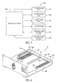
- Figure 1 is a schematic of a power generation system having a battery system and a cooling system in accordance with an exemplary embodiment
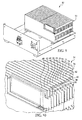
- Figure 2 is a schematic of a portion of a housing, battery modules, and the cooling system utilized in the power generation system of Figure 1 ;
- Figure 3 is a schematic of a top view of the housing, battery modules, and the cooling system utilized in the power generation system of Figure 1 ;
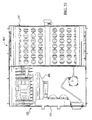
- Figure 4 is a cross-sectional schematic of the power generation system of Figure 1 ;
- FIG. 5 is a block diagram of components of the cooling system utilized in the power generation system of Figure 1 ;
- Figure 6 is a schematic of a portion of the housing and the cooling system utilized in the power generation system of Figure 1 ;
- Figure 7 is another schematic of a portion of the housing and the cooling system utilized in the power generation system of Figure 1 ;
- Figure 8 is another schematic of a portion of the housing, battery modules, and the cooling system utilized in the power generation system of Figure 1 ;
- Figure 9 is another schematic of a portion of a housing, battery modules, and the cooling system utilized in the power generation system of Figure 1 ;
- Figure 10 is an enlarged schematic of a portion of one battery module shown in Figure 9 ;
- Figure 11 is another schematic of a portion of the housing, battery modules, and the cooling system utilized in the power generation system of Figure 1 ;
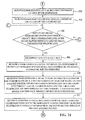
- FIGS. 12-19 are flowcharts of a method for cooling a battery system in accordance with another exemplary embodiment.
- Figure 20 is a schematic of a portion of a housing, battery modules, and the cooling system utilized in another power generation system in accordance with another exemplary embodiment.
- the power generation system 10 includes a battery system 20 and a cooling system 22.
- the battery system 20 is provided to output electrical power.
- the battery system 20 includes the battery modules 24, 26.
- Each of the battery modules 24, 26 has a similar structure and includes a plurality of battery cell assemblies that can be electrically connected in series to one another or in parallel to one another.
- the battery module 24 includes battery cell assemblies 28, 29, 30, 31, 32, 33, 34, 36, 38, 40 and 42 and flow channel manifolds 60, 62, 64, 66, 68, 70, 72, 74, 76 and 78.
- Each of the battery cell assemblies has a battery cell therein that generates an operational voltage between a pair of electrodes extending therefrom.
- each battery cell is a lithium-ion battery cell.
- the battery cells could be nickel-cadmium battery cells or nickel metal hydride battery cells for example.
- other types of battery cells known to those skilled in the art could be utilized.
- the flow channel manifolds are provided to allow air to flow through air channels defined in each flow channel manifold.
- the flow channel manifold 60 has an upper rail member 82, a lower rail member 84, and a plurality of vertical members 86.
- the upper rail member 82 and the lower rail member 84 are disposed substantially parallel to each another.
- the plurality of vertical members 86 are connected between the upper rail member 82 and the lower rail member 84 and are disposed substantially parallel to each other.
- the plurality of vertical members 86 are spaced apart from each other and define a plurality of air flow channels therein. For example, some of the vertical members 86 define air flow channels 100, 102, 104 (on a right side of Figure 4 ) in the flow channel manifold 60. Further, some of the vertical members 86 define air flow channels 106, 108, 110 (on a left side of Figure 4 ) in the flow channel manifold 60.
- the flow channel manifold 60 is disposed between the battery cell assemblies 28, 29, and the flow channel manifold 62 is disposed between the battery cell assemblies 29, 30. Further, the flow channel manifold 64 is disposed between the battery cell assemblies 30, 31, and the flow channel manifold 66 is disposed between the battery cell assemblies 31, 32. Further, the flow channel manifold 68 is disposed between the battery cell assemblies 32, 33 and the flow channel manifold 70 is disposed between the battery cell assemblies 33, 34. Further, the flow channel manifold 72 is disposed between the battery cell assemblies 34, 36, and the flow channel manifold 74 is disposed between the battery cell assemblies 36, 38. Further, the flow channel manifold 76 is disposed between the battery cell assemblies 38, 40, and the flow channel manifold 78 is disposed between the battery cell assemblies 40, 42.
- the cooling system 22 is provided to maintain a battery system 20 within a desired temperature range, and in particular below a threshold temperature level in accordance with an exemplary embodiment is provided.
- the cooling system 22 includes a housing 130, evaporator fans 132, 134, evaporators 136, 138, flow balancing baffles 140, 142, a support member 144, conduit portions 146, 148, 150, flow balancing trays 160, 162, inner side walls 170, 172, 174, a dividing wall 176, a condenser 190, a condenser fan 192, the compressor 194, conduit portions 196, 198, 200, temperature sensors 210, 212, and a microprocessor 220.
- the cooling system 22 can maintain the battery modules 24, 26 within a desired temperature range of 15°-35° Celsius. Of course, other temperature ranges could also be utilized. In another exemplary embodiment, the cooling system 22 can maintain the battery modules 24, 26 at a temperature level less than a threshold temperature level of 40° Celsius. Of course, another threshold temperature level could be utilized.
- the housing 130 is provided to enclose the battery system 20 and the cooling system 22 therein.
- the housing 130 includes a base member 230, a top cover 232 configured to be coupled to the base member 230, and standoff members 234, 236 that are disposed on the bottom surface of the base member 230.
- the housing 130 is constructed from plastic. However, in alternative embodiments other materials known to those skilled in the art could be utilized to construct the housing 130.
- the evaporators 136, 138 are provided to extract heat energy from the battery modules 24, 26, respectively.
- the evaporators 136, 138 are disposed on the base member 230 of the housing 130. Further, the evaporators 136, 138 are disposed in an enclosed portion or space 180 within the housing 130.
- the evaporator 136 is configured to extract heat energy from air in a first closed flow path loop (described below) into a refrigerant flowing through the evaporator 136 to reduce a temperature level of the battery module 24.
- the evaporator 138 is configured to extract heat energy from air in a second closed flow path loop (described below) into a refrigerant flowing through the evaporator 138 to reduce a temperature level of the battery module 26.
- refrigerants include R-11, R-12, R-22, R-134A, R-407C and R-410A for example.
- R-11, R-12, R-22, R-134A, R-407C and R-410A for example.
- other types of refrigerants known to those skilled in the art could be utilized.
- the evaporator 136 is fluidly coupled to the compressor 194 via the conduit portions 200, 146. Further, the evaporator 136 is fluidly coupled to the evaporator 138 via the conduit portion 148. Further, the evaporator 138 is fluidly coupled to the condenser 190 via the conduit portions 150, 196. Further, the condenser 190 is fluidly coupled to the compressor 194 via the conduit portion 198.
- the compressor 194 pumps the refrigerant through a closed loop including the conduit portions 200, 146, the evaporator 136, the conduit portion 148, the evaporator 138, the conduit portions 150, 196, the condenser 190, the conduit portion 198 and back to the compressor 194.
- the evaporator fan 132 is disposed on the base member 230 of the housing 130.
- the evaporator fan 132 is configured to recirculate air in a closed flow path loop 240 within the first enclosed portion 180 of the housing 130.
- the closed flow path loop 240 includes a flow path through the evaporator fan 132, and past the evaporator 136 and then through air flow channels in the battery module 24 and then back through the evaporator fan 132.
- the evaporator fan 134 is disposed on the base member 230 of the housing 130.
- the evaporator fan 134 is configured to recirculate air in a closed flow path loop 242 within the enclosed portion 182 of the housing 130.
- the closed flow path loop 242 includes a flow path through the evaporator fan 134, and past the evaporator 136 and then through air flow channels in the battery module 26 and then back through the evaporator fan 134.
- the flow balancing baffle 140 is disposed proximate to the evaporator fan 132 on the base member 230 of the housing 130.
- the flow balancing baffle 140 is configured to allow a substantially equal amount of air flow through each aperture in the baffle 140 such than air flow is evenly distributed across a surface of the evaporator 136.
- the flow balancing baffle 140 is substantially u-shaped with a plurality of apertures extending therethrough and is constructed from plastic.
- the flow balancing baffle 142 is disposed proximate to the evaporator fan 134 on the base member 230 of the housing 130.
- the flow balancing baffle 142 is configured to allow a substantially equal amount of air flow through each aperture in the baffle 142 such than air flow is evenly distributed across a surface of the evaporator 138.
- the flow balancing baffle 142 is substantially u-shaped with a plurality of apertures extending therethrough and is constructed from plastic.
- the support member 144 is disposed on the base member 230 of the housing 130 between the evaporators 136, 138.
- the support member 144 is substantially u-shaped and is constructed from plastic.
- the conduit portion 146 is fluidly coupled to a first end of the evaporator 136.
- the conduit portion 148 is fluidly coupled between a second end of the evaporator 136 and a first end of the evaporator 138.
- the conduit 150 is fluidly coupled to a second end of the evaporator 138.
- the flow balancing tray 160 is disposed on the flow balancing baffles 140, 142 and the support member 144 in the enclosed portion 180 of the housing 130.
- the flow balancing tray 160 is configured to allow a substantially equal amount of air flow through each aperture in the tray 160 such that air flow is evenly distributed across lower surfaces of the battery modules 24, 26. Further, the flow balancing tray 160 is configured to hold the battery modules 24, 26 thereon.
- the flow balancing tray 160 has a plurality of apertures extending therethrough and is constructed from plastic.
- the flow balancing tray 162 is disposed on a top surface of the battery modules 24, 26 in the housing 130.
- the flow balancing tray 162 is configured to allow a substantially equal amount of air flow through each aperture in the tray 162 such than air flow is evenly distributed from the battery modules 24, 26 through the flow balancing tray 162.
- the flow balancing tray 162 has a plurality of apertures extending therethrough and is constructed from plastic.
- the inner side walls 170, 172, 174 and the dividing wall 176 are disposed proximate to side walls of the battery modules 24, 26.
- the dividing wall 176 has a sealing gasket 177 disposed on an outer periphery of the dividing wall 176 to form an airtight seal with the base member 230 and the top cover 232 that contact the outer periphery of the dividing wall 176.
- the base member 230, the top cover 232 and the dividing wall 176 define an enclosed portion 180 having the battery modules 24, 26 disposed therein. It should be noted that the enclosed portion 180 is an airtight enclosed portion.
- the base member 230, the top cover 232 and the dividing wall 176 define an enclosed portion 184.
- the enclosed portion 184 fluidly communicates with ambient air external to the housing 130.
- the inner side walls 170, 172, 174 and the dividing wall 176 are constructed from plastic.
- the condenser 190 is disposed in the enclosed portion 182 of the housing 130 and is fluidly coupled to the evaporators 136, 138 and the compressor 194. As shown, the condenser 190 is fluidly coupled to the evaporator 138 via the conduit portions 150, 196. Further, the condenser 190 is fluidly coupled to the compressor 194 via the conduit portion 198.
- the condenser 190 is configured to receive heat energy in a refrigerant from the evaporators 136, 138 and to dissipate the heat energy in the received refrigerant such that the heat energy is removed from the refrigerant for cooling the battery modules 24, 26.
- the condenser fan 192 is configured to urge air past the condenser 190 to induce the condenser 190 to dissipate heat energy in response to a control signal from the microprocessor 220. As shown, the condenser fan 192 is disposed proximate to the condenser 190 in the enclosed region 182.
- the compressor 194 is configured to pump and recirculate refrigerant through the evaporators 136, 138 in response to a control signal from the microprocessor 220.
- the compressor 194 pumps the refrigerant through a closed loop including the conduit portions 200, 146, the evaporator 136, the conduit portion 148, the evaporator 138, the conduit portions 150, 190, the condenser 190, and the conduit portion 198 back to the compressor 194.
- the compressor 194 is disposed in the enclosed region 182.
- the temperature sensor 210 is electrically coupled to the microprocessor 220 and is disposed proximate to the battery module 24.
- the temperature sensor 210 is configured to generate a signal indicative of a temperature of the battery module 24 that is received by the microprocessor 220.
- the temperature sensor 212 is electrically coupled to the microprocessor 220 and is disposed proximate to the battery module 26.
- the temperature sensor 212 is configured to generate a signal indicative of a temperature of the battery module 26 that is received by the microprocessor 220.
- the microprocessor 212 is configured to control operation of the cooling system 22. As shown, the microprocessor 212 is electrically coupled to the evaporator fans 132, 134, the condenser fan 192, the compressor 194, and the temperature sensors 210, 212. During operation, the microprocessor 212 receive signals from the temperature sensors 210, 212 indicative of temperatures of the battery modules 24, 26, respectively. Based on the received signals from the temperature sensors 210, 212, the microprocessor 212 generates control signals for controlling operation of the evaporator fans 132, 134, the condenser fan 192, and the compressor 194, as will be explained in greater detail below.
- step 260 the microprocessor 220 initializes the following flags: flag1 equals "false”; flag2 equals “false”; flag3 equals “false”; and frag4 equals "false.” After step 260, the method advances to step 262.
- the temperature sensor 210 generates a first signal indicative of a temperature of the battery module 24 disposed in the enclosed portion 180 of the housing 130 that is received by the microprocessor 220. After step 262, the method advances to step 264.
- step 264 the temperature sensor 212 generates a second signal indicative of a temperature of the battery module 26 disposed in the enclosed portion 180 of the housing 130 that is received by the microprocessor 220. After step 264, the method advances to step 266.
- the microprocessor 220 makes a determination as to whether the first signal from the temperature sensor 210 indicates that a temperature level of the battery module 24 is greater than a threshold temperature level. If the value of step 266 equals "yes", the method advances to step 268. Otherwise, the method advances to step 286.
- step 268 the microprocessor 220 sets flag1 equal to "true.” After step 268, the method advances to step 270.
- the microprocessor 220 generates a signal to turn on the compressor 194 to recirculate refrigerant through evaporators 132, 134 disposed proximate to battery module 24, 26, respectively in the enclosed portion 180 of the housing 130, and through the condenser 190 disposed in the enclosed portion 182 of the housing 130.
- the method advances to step 280.
- the microprocessor 220 generates a signal to turn on the evaporator fan 132 to recirculate air in a first closed flow path loop 240 (shown in Figure 4 ) within the enclosed portion 180.
- the first closed flow path loop 240 includes a flow path through the evaporator fan 132 and past the evaporator 136 and then through air flow channels in the battery module 24 and then back through the evaporator fan 132.
- the method advances to step 282.
- the evaporator 136 extracts heat energy from the air in the first closed flow path loop 240 to the refrigerant flowing through the evaporator 136 to reduce a temperature of the battery module 24 in the enclosed portion 180. After step 282, the method advances to step 284.
- step 284 the microprocessor 220 generates a signal to turn on the condenser fan 192 to urge air past the condenser 190 in the enclosed portion 182 that further induces the condenser 190 to dissipate heat energy from the refrigerant flowing from the evaporator 136.
- step 284 the method advances to step 304.
- step 266 when the value of step 266 equals "no", the method advances to step 286.
- step 286 the microprocessor 220 sets flag1 equal to "false.” After step 286, the method advances to step 288.
- step 288 the microprocessor 220 makes a determination as to whether the flag4 equals "false.” If the value of step 288 equals "yes", the method advances to step 290. Otherwise, the method advances to step 292.
- step 290 the microprocessor 220 removes a signal from the evaporator fan 132 to turn off the evaporator fan 132. After step 290, the method advances to step 292.
- step 292 the microprocessor 220 makes a determination as to whether the flag2 equals "false”; flag3 equals “false” and flag4 equals "false.” If the value of step 292 equals "yes”, the method advances to step 300. Otherwise, the method advances to step 304.
- step 300 the microprocessor 220 removes a signal from the compressor 194 to turn off the compressor 194. After step 300, the method advances to step 302.
- step 302 the microprocessor 220 removes a signal from the condenser fan 192 to turn off the condenser fan 192. After step 302, the method advances to step 304.
- step 304 the microprocessor 220 makes a determination as to whether the second signal from temperature sensor 212 indicates that a temperature level of the battery module 26 is greater than the threshold temperature level. If the value of step 304 equals "yes", the method advances to step 306. Otherwise, the method advances to step 316.
- step 306 the microprocessor 220 sets flag2 equal to "true.” After step 306, the method advances to step 308.
- step 308 the microprocessor 220 generates a signal to turn on the compressor 194 to recirculate refrigerant through the evaporator 136, the evaporator 138, and the condenser 190.
- step 308 the method advances to step 310.
- the microprocessor 220 generates a signal to turn on the evaporator fan 134 to recirculate air in a second closed flow path loop 242 (shown in Figure 4 ) within the enclosed portion 180.
- the second closed flow path loop 242 includes a flow path through the evaporator fan 134 and past the evaporator 138 and then through air flow channels in the battery module 26 and then back through the evaporator fan 134.
- the evaporator 138 extracts heat energy from the air in the second closed flow path loop 242 to the refrigerant flowing through the evaporator 138 to reduce a temperature of the battery module 26 in the enclosed portion 180. After step 312, the method advances to step 314.
- step 314 the microprocessor 220 generates a signal to turn on the condenser fan 192 to urge air past the condenser 190 in the enclosed portion 182 that further induces the condenser 190 to dissipate heat energy from the refrigerant flowing from the evaporator 138.
- step 330 the method advances to step 330.
- step 304 if the value of step 304 equals "no", the method advances to step 316.
- step 316 the microprocessor 220 sets flag2 equal to "false.” After step 316, the method advances to step 318.
- step 318 the microprocessor 220 makes a determination as to whether the flag3 equals "false.” If the value of step 318 equals "yes", the method advances to step 320. Otherwise, the method advances to step 322.
- step 320 the microprocessor 220 removes a signal from the evaporator fan 134 to turn off the evaporator fan 134. After step 320, the method advances to step 322.
- step 322 the microprocessor 220 makes a determination as to whether the flag1 equals "false”; flag3 equals “false”; and flag4 equals "false.” If the value of step 322 equals "yes”, the method advances to step 324. Otherwise, the method advances to step 330.
- step 324 the microprocessor 220 removes a signal from the compressor 194 to turn off the compressor 194. After step 324, the method advances to step 326.
- step 326 the microprocessor 220 removes a signal from the condenser fan 192 to turn off the condenser fan 192.
- step 326 the method advances to step 330.
- step 332 the microprocessor 220 makes a determination as to whether the first temperature difference value is greater than a threshold difference value. If the value of step 332 equals "yes”, the method advances to step 334. Otherwise, the method advances to step 340.
- step 334 the microprocessor 220 sets flag3 equal to "true.” After step 334, the method advances to step 335.
- step 335 the microprocessor 220 generates a signal to turn on the compressor 194 to recirculate refrigerant through the evaporator 136, the evaporator 138, and the condenser 190.
- step 336 the method advances to step 336.
- step 336 the microprocessor 220 generates a signal to turn on the evaporator fan 134 to recirculate air in the second closed flow path loop 242 within the enclosed portion 180.
- step 337 the method advances to step 337.
- the evaporator 138 extracts heat energy from the air in the second closed flow path loop 242 to the refrigerant flowing through the evaporator 138 to reduce a temperature of the battery module 26 in the enclosed portion 180.
- the method advances to step 338.
- the microprocessor 220 generates a signal to turn on the condenser fan 192 to urge air past the condenser 190 in the enclosed portion 182 of the housing 130 that further induces the condenser 190 to dissipate heat energy from the refrigerant flowing from the evaporator 138.
- the method advances to step 360.
- step 340 the microprocessor 220 sets flag3 equal to "false.” After step 340, the method advances to step 342.
- step 342 the microprocessor 220 makes a determination as to whether the flag2 equals "false.” If the value of step 342 equals "yes”, the method advances to step 344. Otherwise, the method advances to step 346.
- step 344 the microprocessor 220 removes a signal from the evaporator fan 134 to turn off the evaporator fan 134. After step 344, the method advances to step 346.
- step 346 the microprocessor makes a determination as to whether the flag1 equals "false”; flag2 equals “false”; and flag4 equals "false.” If the value of step 346 equals "yes”, the method advances to step 348. Otherwise, the method advances to step 360.
- step 348 the microprocessor 220 removes a signal from the compressor 194 to turn off the compressor 194. After step 348, the method advances to step 350.
- step 350 the microprocessor 220 removes a signal from the condenser fan 192 to turn off the condenser fan 192. After step 350, the method advances to step 360.
- step 362 the microprocessor makes a determination as to whether the second temperature difference value is greater than a threshold difference value. If the value of step 362 equals "yes", the method advances to step 364. Otherwise, the method advances to step 380.
- step 364 the microprocessor 220 sets flag4 equal to "true.” After step 364, the method advances to step 366.
- step 366 the microprocessor 220 generates a signal to turn on the compressor 194 to recirculate refrigerant through the evaporator 136, the evaporator 138, and the condenser 190.
- step 368 the method advances to step 368.
- step 368 the microprocessor 220 generates a signal to turn on the evaporator fan 132 to recirculate air in the first closed flow path loop 240 within the enclosed portion 180.
- step 370 the method advances to step 370.
- the evaporator 136 extracts heat energy from the air in the first closed flow path loop 240 to the refrigerant flowing through the evaporator 136 to reduce a temperature of the battery module 24 in the enclosed portion 180.
- the method advances to step 372.
- the microprocessor 220 generates a signal to turn on the condenser fan 192 to urge air past the condenser 190 in the enclosed portion 182 of the housing 130 that further induces the condenser 190 to dissipate heat energy from the refrigerant flowing from the evaporator 136.
- the method returns to step 262.
- step 380 the microprocessor 220 sets flag4 equal to "false.” After step 380, the method advances to step 382.
- step 382 the microprocessor 220 makes a determination as to whether flag1 equals "false.” After step 382, the method advances to step 384.
- step 384 the microprocessor 220 removes a signal from the evaporator fan 132 to turn off the evaporator fan 132. After step 384, the method advances to step 386.
- step 386 the microprocessor 220 makes a determination as to whether flag1 equals "false”; and flag2 equals “false”; and flag3 equals "false.” If the value of step 386 equals "yes”, the method advances to step 388. Otherwise, the method returns to step 262.
- step 388 the microprocessor 220 removes a signal from the compressor 194 to turn off the compressor 194. After step 388, the method advances to step 390.
- step 390 the microprocessor 220 removes a signal from the condenser fan 192 to turn off the condenser fan 192. After step 390, the method returns to step 262.
- the power generation system 418 includes a battery system 420 and a cooling system 422.
- the battery system 420 has a substantially similar configuration as the battery system 20.
- the cooling system 422 has a cooling coil 424 and a condenser 490, and further includes the other components of the cooling system 22 described above except for the condenser fan 192 and the condenser 190.
- the cooling coil 424 is utilized to cool the refrigerant and replaces the condenser fan 192 utilized in the system 10.
- the condenser 490 replaces the condenser 190 utilized in the cooling system 22.
- the cooling coil 424 receives a liquid from an external liquid source which cools the refrigerant flowing therethrough. It should be noted that the operation of the cooling system 422 is similar to the operation of the cooling system 22 described above, except that the cooling coil 424 is utilized instead of a condenser fan to cool the refrigerant.
- the cooling system for a battery system and the method for cooling the battery system provide a substantial advantage over other cooling systems and methods.
- the cooling system and method provide a technical effect of recirculating air in a closed flow path loop within a housing of the cooling system to reduce a temperature level of the battery modules in the battery system.
- the closed flow path loop is within an airtight enclosed portion of the housing that allows the system and the method to utilize less power and have a smaller size than other systems and methods.
Landscapes
- Engineering & Computer Science (AREA)
- Manufacturing & Machinery (AREA)
- Chemical & Material Sciences (AREA)
- Chemical Kinetics & Catalysis (AREA)
- Electrochemistry (AREA)
- General Chemical & Material Sciences (AREA)
- Automation & Control Theory (AREA)
- Secondary Cells (AREA)
- Battery Mounting, Suspending (AREA)
Abstract
Description
- This application relates to a cooling system for a battery system and a method for cooling the battery system.
- In a typical air-cooled battery pack, ambient air from ambient atmosphere is directed across battery cells in the battery pack and is subsequently exhausted from the battery pack. However, the typical air-cooled battery pack has a major challenge in maintaining a temperature of the battery pack within a desired temperature range.
- In particular, a maximum operating temperature of the battery cells can often be less than a temperature of ambient air utilized to cool the batteries. In this situation, it is impossible to maintain the battery cells within a desired temperature range in an air-cooled battery pack.
- Accordingly, the inventors herein have recognized a need for an improved battery cell assembly that minimizes and/or eliminates the above-mentioned deficiency.
- A cooling system for a battery system in accordance with an exemplary embodiment is provided. The cooling system includes a housing having a first enclosed portion and a second enclosed portion. The first enclosed portion is configured to receive a first battery module therein. The cooling system further includes a first evaporator disposed in the first enclosed portion. The cooling system further includes a first evaporator fan disposed proximate to the first evaporator in the first enclosed portion configured to recirculate air in a first closed flow path loop within the first enclosed portion. The first evaporator is configured to extract heat energy from the air in the first closed flow path loop to reduce a temperature level of the first battery module. The cooling system further includes a condenser disposed in the second enclosed portion and fluidly coupled to the first evaporator. The condenser is configured to receive heat energy in a refrigerant from the first evaporator and to dissipate the heat energy. The cooling system further includes a compressor disposed in the second enclosed portion that recirculates the refrigerant through the first evaporator and the condenser.
- A method for cooling a battery system utilizing a cooling system in accordance with another exemplary embodiment is provided. The cooling system has a housing, a first evaporator, a first evaporator fan, and a condenser. The housing has a first enclosed portion and a second enclosed portion. The first enclosed portion is configured to receive a first battery module therein. The method includes recirculating air in a first closed flow path loop within the first enclosed portion utilizing the first evaporator fan. The first evaporator is configured to extract heat energy from the air in the first closed flow path loop to reduce a temperature level of the first battery module in the first enclosed portion of the housing. The method further includes receiving heat energy in a refrigerant from the first evaporator in a condenser disposed in the second enclosed portion of the housing and dissipating the heat energy utilizing the condenser. The method further includes recirculating the refrigerant through the first evaporator and the condenser utilizing a compressor disposed in the second enclosed portion.
-
Figure 1 is a schematic of a power generation system having a battery system and a cooling system in accordance with an exemplary embodiment; -
Figure 2 is a schematic of a portion of a housing, battery modules, and the cooling system utilized in the power generation system ofFigure 1 ; -
Figure 3 is a schematic of a top view of the housing, battery modules, and the cooling system utilized in the power generation system ofFigure 1 ; -
Figure 4 is a cross-sectional schematic of the power generation system ofFigure 1 ; -
Figure 5 is a block diagram of components of the cooling system utilized in the power generation system ofFigure 1 ; -
Figure 6 is a schematic of a portion of the housing and the cooling system utilized in the power generation system ofFigure 1 ; -
Figure 7 is another schematic of a portion of the housing and the cooling system utilized in the power generation system ofFigure 1 ; -
Figure 8 is another schematic of a portion of the housing, battery modules, and the cooling system utilized in the power generation system ofFigure 1 ; -
Figure 9 is another schematic of a portion of a housing, battery modules, and the cooling system utilized in the power generation system ofFigure 1 ; -
Figure 10 is an enlarged schematic of a portion of one battery module shown inFigure 9 ; -
Figure 11 is another schematic of a portion of the housing, battery modules, and the cooling system utilized in the power generation system ofFigure 1 ; -
Figures 12-19 are flowcharts of a method for cooling a battery system in accordance with another exemplary embodiment; and -
Figure 20 is a schematic of a portion of a housing, battery modules, and the cooling system utilized in another power generation system in accordance with another exemplary embodiment. - Referring to
Figures 1-3 , apower generation system 10 for outputting electrical power in accordance with an exemplary embodiment is illustrated. Thepower generation system 10 includes abattery system 20 and acooling system 22. - The
battery system 20 is provided to output electrical power. Thebattery system 20 includes thebattery modules battery modules battery module 24 will be described in detail. For example, referring toFigures 8-10 , thebattery module 24 includesbattery cell assemblies - The flow channel manifolds are provided to allow air to flow through air channels defined in each flow channel manifold. The air that flows through a flow channel manifold that is disposed between adjacent battery cell assemblies, extracts heat energy from the adjacent battery cell assemblies.
- For example, referring to
Figure 4 , a brief explanation of theflow channel manifold 60 will be provided. It should be noted that the structure of flow channel manifolds 62, 64, 66, 68. 70, 72, 74, 76 and 78 have the same structure asflow channel manifold 60. As shown, theflow channel manifold 60 has anupper rail member 82, alower rail member 84, and a plurality ofvertical members 86. Theupper rail member 82 and thelower rail member 84 are disposed substantially parallel to each another. The plurality ofvertical members 86 are connected between theupper rail member 82 and thelower rail member 84 and are disposed substantially parallel to each other. The plurality ofvertical members 86 are spaced apart from each other and define a plurality of air flow channels therein. For example, some of thevertical members 86 defineair flow channels Figure 4 ) in theflow channel manifold 60. Further, some of thevertical members 86 defineair flow channels Figure 4 ) in theflow channel manifold 60. - Referring to
Figure 10 , theflow channel manifold 60 is disposed between thebattery cell assemblies flow channel manifold 62 is disposed between thebattery cell assemblies flow channel manifold 64 is disposed between thebattery cell assemblies flow channel manifold 66 is disposed between thebattery cell assemblies flow channel manifold 68 is disposed between thebattery cell assemblies flow channel manifold 70 is disposed between thebattery cell assemblies flow channel manifold 72 is disposed between thebattery cell assemblies flow channel manifold 74 is disposed between thebattery cell assemblies flow channel manifold 76 is disposed between thebattery cell assemblies flow channel manifold 78 is disposed between thebattery cell assemblies - Referring to
Figures 2 ,3 and5-8 , thecooling system 22 is provided to maintain abattery system 20 within a desired temperature range, and in particular below a threshold temperature level in accordance with an exemplary embodiment is provided. Thecooling system 22 includes ahousing 130,evaporator fans evaporators flow balancing baffles support member 144,conduit portions flow balancing trays inner side walls wall 176, acondenser 190, acondenser fan 192, thecompressor 194,conduit portions temperature sensors microprocessor 220. In one exemplary embodiment, thecooling system 22 can maintain thebattery modules cooling system 22 can maintain thebattery modules - Referring to
Figure 1 , thehousing 130 is provided to enclose thebattery system 20 and thecooling system 22 therein. Thehousing 130 includes abase member 230, atop cover 232 configured to be coupled to thebase member 230, andstandoff members base member 230. In one exemplary embodiment, thehousing 130 is constructed from plastic. However, in alternative embodiments other materials known to those skilled in the art could be utilized to construct thehousing 130. - Referring to
Figures 1 ,6 and8 , theevaporators battery modules evaporators base member 230 of thehousing 130. Further, theevaporators space 180 within thehousing 130. Theevaporator 136 is configured to extract heat energy from air in a first closed flow path loop (described below) into a refrigerant flowing through theevaporator 136 to reduce a temperature level of thebattery module 24. Similarly, theevaporator 138 is configured to extract heat energy from air in a second closed flow path loop (described below) into a refrigerant flowing through theevaporator 138 to reduce a temperature level of thebattery module 26. Exemplary refrigerants include R-11, R-12, R-22, R-134A, R-407C and R-410A for example. Of course, other types of refrigerants known to those skilled in the art could be utilized. - Referring to
Figures 3 ,4 and6 , a refrigerant flow path in thecooling system 22 will now be explained. As shown, theevaporator 136 is fluidly coupled to thecompressor 194 via theconduit portions evaporator 136 is fluidly coupled to theevaporator 138 via theconduit portion 148. Further, theevaporator 138 is fluidly coupled to thecondenser 190 via theconduit portions condenser 190 is fluidly coupled to thecompressor 194 via theconduit portion 198. During operation, thecompressor 194 pumps the refrigerant through a closed loop including theconduit portions evaporator 136, theconduit portion 148, theevaporator 138, theconduit portions condenser 190, theconduit portion 198 and back to thecompressor 194. - Referring to
Figures 4 and6 , theevaporator fan 132 is disposed on thebase member 230 of thehousing 130. Theevaporator fan 132 is configured to recirculate air in a closedflow path loop 240 within the firstenclosed portion 180 of thehousing 130. The closedflow path loop 240 includes a flow path through theevaporator fan 132, and past theevaporator 136 and then through air flow channels in thebattery module 24 and then back through theevaporator fan 132. - The
evaporator fan 134 is disposed on thebase member 230 of thehousing 130. Theevaporator fan 134 is configured to recirculate air in a closedflow path loop 242 within theenclosed portion 182 of thehousing 130. The closedflow path loop 242 includes a flow path through theevaporator fan 134, and past theevaporator 136 and then through air flow channels in thebattery module 26 and then back through theevaporator fan 134. - The
flow balancing baffle 140 is disposed proximate to theevaporator fan 132 on thebase member 230 of thehousing 130. Theflow balancing baffle 140 is configured to allow a substantially equal amount of air flow through each aperture in thebaffle 140 such than air flow is evenly distributed across a surface of theevaporator 136. In one exemplary embodiment theflow balancing baffle 140 is substantially u-shaped with a plurality of apertures extending therethrough and is constructed from plastic. - The
flow balancing baffle 142 is disposed proximate to theevaporator fan 134 on thebase member 230 of thehousing 130. Theflow balancing baffle 142 is configured to allow a substantially equal amount of air flow through each aperture in thebaffle 142 such than air flow is evenly distributed across a surface of theevaporator 138. In one exemplary embodiment, theflow balancing baffle 142 is substantially u-shaped with a plurality of apertures extending therethrough and is constructed from plastic. - The
support member 144 is disposed on thebase member 230 of thehousing 130 between theevaporators support member 144 is substantially u-shaped and is constructed from plastic. - Referring to
Figure 6 , theconduit portion 146 is fluidly coupled to a first end of theevaporator 136. Theconduit portion 148 is fluidly coupled between a second end of theevaporator 136 and a first end of theevaporator 138. Further, theconduit 150 is fluidly coupled to a second end of theevaporator 138. Thus, refrigerant can flow through theconduit portion 160, theevaporator 136, theconduit portion 148, theevaporator 138, and theconduit 150. - Referring to
Figure 7 , theflow balancing tray 160 is disposed on the flow balancing baffles 140, 142 and thesupport member 144 in theenclosed portion 180 of thehousing 130. Theflow balancing tray 160 is configured to allow a substantially equal amount of air flow through each aperture in thetray 160 such that air flow is evenly distributed across lower surfaces of thebattery modules flow balancing tray 160 is configured to hold thebattery modules flow balancing tray 160 has a plurality of apertures extending therethrough and is constructed from plastic. - Referring to
Figure 11 , theflow balancing tray 162 is disposed on a top surface of thebattery modules housing 130. Theflow balancing tray 162 is configured to allow a substantially equal amount of air flow through each aperture in thetray 162 such than air flow is evenly distributed from thebattery modules flow balancing tray 162. In one exemplary embodiment, theflow balancing tray 162 has a plurality of apertures extending therethrough and is constructed from plastic. - Referring to
Figures 1 and11 , theinner side walls wall 176 are disposed proximate to side walls of thebattery modules wall 176 has a sealinggasket 177 disposed on an outer periphery of the dividingwall 176 to form an airtight seal with thebase member 230 and thetop cover 232 that contact the outer periphery of the dividingwall 176. Further, thebase member 230, thetop cover 232 and the dividingwall 176 define anenclosed portion 180 having thebattery modules enclosed portion 180 is an airtight enclosed portion. Further, thebase member 230, thetop cover 232 and the dividingwall 176 define an enclosed portion 184. In one exemplary embodiment, the enclosed portion 184 fluidly communicates with ambient air external to thehousing 130. In one exemplary embodiment, theinner side walls wall 176 are constructed from plastic. - Referring to
Figures 3 and6 , thecondenser 190 is disposed in theenclosed portion 182 of thehousing 130 and is fluidly coupled to theevaporators compressor 194. As shown, thecondenser 190 is fluidly coupled to theevaporator 138 via theconduit portions condenser 190 is fluidly coupled to thecompressor 194 via theconduit portion 198. Thecondenser 190 is configured to receive heat energy in a refrigerant from theevaporators battery modules - Referring to
Figures 3 and5 , thecondenser fan 192 is configured to urge air past thecondenser 190 to induce thecondenser 190 to dissipate heat energy in response to a control signal from themicroprocessor 220. As shown, thecondenser fan 192 is disposed proximate to thecondenser 190 in theenclosed region 182. - Referring to
Figures 3 ,5 and 6 , thecompressor 194 is configured to pump and recirculate refrigerant through theevaporators microprocessor 220. In particular, thecompressor 194 pumps the refrigerant through a closed loop including theconduit portions evaporator 136, theconduit portion 148, theevaporator 138, theconduit portions condenser 190, and theconduit portion 198 back to thecompressor 194. As shown, thecompressor 194 is disposed in theenclosed region 182. - Referring to
Figures 3 and5 , thetemperature sensor 210 is electrically coupled to themicroprocessor 220 and is disposed proximate to thebattery module 24. Thetemperature sensor 210 is configured to generate a signal indicative of a temperature of thebattery module 24 that is received by themicroprocessor 220. - The
temperature sensor 212 is electrically coupled to themicroprocessor 220 and is disposed proximate to thebattery module 26. Thetemperature sensor 212 is configured to generate a signal indicative of a temperature of thebattery module 26 that is received by themicroprocessor 220. - The
microprocessor 212 is configured to control operation of thecooling system 22. As shown, themicroprocessor 212 is electrically coupled to theevaporator fans condenser fan 192, thecompressor 194, and thetemperature sensors microprocessor 212 receive signals from thetemperature sensors battery modules temperature sensors microprocessor 212 generates control signals for controlling operation of theevaporator fans condenser fan 192, and thecompressor 194, as will be explained in greater detail below. - Referring to
Figures 12-19 , a flowchart of a method for cooling thebattery system 20 will now be explained. - At
step 260, themicroprocessor 220 initializes the following flags: flag1 equals "false"; flag2 equals "false"; flag3 equals "false"; and frag4 equals "false." Afterstep 260, the method advances to step 262. - At
step 262, thetemperature sensor 210 generates a first signal indicative of a temperature of thebattery module 24 disposed in theenclosed portion 180 of thehousing 130 that is received by themicroprocessor 220. Afterstep 262, the method advances to step 264. - At
step 264, thetemperature sensor 212 generates a second signal indicative of a temperature of thebattery module 26 disposed in theenclosed portion 180 of thehousing 130 that is received by themicroprocessor 220. Afterstep 264, the method advances to step 266. - At
step 266, themicroprocessor 220 makes a determination as to whether the first signal from thetemperature sensor 210 indicates that a temperature level of thebattery module 24 is greater than a threshold temperature level. If the value ofstep 266 equals "yes", the method advances to step 268. Otherwise, the method advances to step 286. - At
step 268, themicroprocessor 220 sets flag1 equal to "true." Afterstep 268, the method advances to step 270. - At
step 270, themicroprocessor 220 generates a signal to turn on thecompressor 194 to recirculate refrigerant throughevaporators battery module enclosed portion 180 of thehousing 130, and through thecondenser 190 disposed in theenclosed portion 182 of thehousing 130. Afterstep 270, the method advances to step 280. - At
step 280, themicroprocessor 220 generates a signal to turn on theevaporator fan 132 to recirculate air in a first closed flow path loop 240 (shown inFigure 4 ) within theenclosed portion 180. The first closedflow path loop 240 includes a flow path through theevaporator fan 132 and past theevaporator 136 and then through air flow channels in thebattery module 24 and then back through theevaporator fan 132. Afterstep 280, the method advances to step 282. - At
step 282, theevaporator 136 extracts heat energy from the air in the first closedflow path loop 240 to the refrigerant flowing through theevaporator 136 to reduce a temperature of thebattery module 24 in theenclosed portion 180. Afterstep 282, the method advances to step 284. - At
step 284, themicroprocessor 220 generates a signal to turn on thecondenser fan 192 to urge air past thecondenser 190 in theenclosed portion 182 that further induces thecondenser 190 to dissipate heat energy from the refrigerant flowing from theevaporator 136. Afterstep 284, the method advances to step 304. - Referring again to step 266, when the value of
step 266 equals "no", the method advances to step 286. Atstep 286, themicroprocessor 220 sets flag1 equal to "false." Afterstep 286, the method advances to step 288. - At
step 288, themicroprocessor 220 makes a determination as to whether the flag4 equals "false." If the value ofstep 288 equals "yes", the method advances to step 290. Otherwise, the method advances to step 292. - At
step 290, themicroprocessor 220 removes a signal from theevaporator fan 132 to turn off theevaporator fan 132. Afterstep 290, the method advances to step 292. - At
step 292, themicroprocessor 220 makes a determination as to whether the flag2 equals "false"; flag3 equals "false" and flag4 equals "false." If the value ofstep 292 equals "yes", the method advances to step 300. Otherwise, the method advances to step 304. - At
step 300, themicroprocessor 220 removes a signal from thecompressor 194 to turn off thecompressor 194. Afterstep 300, the method advances to step 302. - At
step 302, themicroprocessor 220 removes a signal from thecondenser fan 192 to turn off thecondenser fan 192. Afterstep 302, the method advances to step 304. - At
step 304, themicroprocessor 220 makes a determination as to whether the second signal fromtemperature sensor 212 indicates that a temperature level of thebattery module 26 is greater than the threshold temperature level. If the value ofstep 304 equals "yes", the method advances to step 306. Otherwise, the method advances to step 316. - At step 306, the
microprocessor 220 sets flag2 equal to "true." After step 306, the method advances to step 308. - At
step 308, themicroprocessor 220 generates a signal to turn on thecompressor 194 to recirculate refrigerant through theevaporator 136, theevaporator 138, and thecondenser 190. Afterstep 308, the method advances to step 310. - At
step 310, themicroprocessor 220 generates a signal to turn on theevaporator fan 134 to recirculate air in a second closed flow path loop 242 (shown inFigure 4 ) within theenclosed portion 180. The second closedflow path loop 242 includes a flow path through theevaporator fan 134 and past theevaporator 138 and then through air flow channels in thebattery module 26 and then back through theevaporator fan 134. Afterstep 310, the method advances to step 312. - At
step 312, theevaporator 138 extracts heat energy from the air in the second closedflow path loop 242 to the refrigerant flowing through theevaporator 138 to reduce a temperature of thebattery module 26 in theenclosed portion 180. Afterstep 312, the method advances to step 314. - At
step 314, themicroprocessor 220 generates a signal to turn on thecondenser fan 192 to urge air past thecondenser 190 in theenclosed portion 182 that further induces thecondenser 190 to dissipate heat energy from the refrigerant flowing from theevaporator 138. Afterstep 314, the method advances to step 330. - Referring again to step 304, if the value of
step 304 equals "no", the method advances to step 316. Atstep 316, themicroprocessor 220 sets flag2 equal to "false." Afterstep 316, the method advances to step 318. - At
step 318, themicroprocessor 220 makes a determination as to whether the flag3 equals "false." If the value ofstep 318 equals "yes", the method advances to step 320. Otherwise, the method advances to step 322. - At
step 320, themicroprocessor 220 removes a signal from theevaporator fan 134 to turn off theevaporator fan 134. Afterstep 320, the method advances to step 322. - At
step 322, themicroprocessor 220 makes a determination as to whether the flag1 equals "false"; flag3 equals "false"; and flag4 equals "false." If the value ofstep 322 equals "yes", the method advances to step 324. Otherwise, the method advances to step 330. - At
step 324, themicroprocessor 220 removes a signal from thecompressor 194 to turn off thecompressor 194. Afterstep 324, the method advances to step 326. - At
step 326, themicroprocessor 220 removes a signal from thecondenser fan 192 to turn off thecondenser fan 192. Afterstep 326, the method advances to step 330. - At
step 330, themicroprocessor 220 calculates a first temperature difference value utilizing the following equation: first temperature difference value = second signal - first signal. Afterstep 330, the method advances to step 332. - At
step 332, themicroprocessor 220 makes a determination as to whether the first temperature difference value is greater than a threshold difference value. If the value ofstep 332 equals "yes", the method advances to step 334. Otherwise, the method advances to step 340. - At
step 334, themicroprocessor 220 sets flag3 equal to "true." Afterstep 334, the method advances to step 335. - At
step 335, themicroprocessor 220 generates a signal to turn on thecompressor 194 to recirculate refrigerant through theevaporator 136, theevaporator 138, and thecondenser 190. Afterstep 335, the method advances to step 336. - At
step 336, themicroprocessor 220 generates a signal to turn on theevaporator fan 134 to recirculate air in the second closedflow path loop 242 within theenclosed portion 180. Afterstep 336, the method advances to step 337. - At
step 337, theevaporator 138 extracts heat energy from the air in the second closedflow path loop 242 to the refrigerant flowing through theevaporator 138 to reduce a temperature of thebattery module 26 in theenclosed portion 180. Afterstep 337, the method advances to step 338. - At
step 338, themicroprocessor 220 generates a signal to turn on thecondenser fan 192 to urge air past thecondenser 190 in theenclosed portion 182 of thehousing 130 that further induces thecondenser 190 to dissipate heat energy from the refrigerant flowing from theevaporator 138. Afterstep 338, the method advances to step 360. - Referring again to step 332, when the value of
step 332 equals "no", the method advances to step 340. Atstep 340, themicroprocessor 220 sets flag3 equal to "false." Afterstep 340, the method advances to step 342. - At
step 342, themicroprocessor 220 makes a determination as to whether the flag2 equals "false." If the value ofstep 342 equals "yes", the method advances to step 344. Otherwise, the method advances to step 346. - At
step 344, themicroprocessor 220 removes a signal from theevaporator fan 134 to turn off theevaporator fan 134. Afterstep 344, the method advances to step 346. - At
step 346, the microprocessor makes a determination as to whether the flag1 equals "false"; flag2 equals "false"; and flag4 equals "false." If the value ofstep 346 equals "yes", the method advances to step 348. Otherwise, the method advances to step 360. - At
step 348, themicroprocessor 220 removes a signal from thecompressor 194 to turn off thecompressor 194. Afterstep 348, the method advances to step 350. - At
step 350, themicroprocessor 220 removes a signal from thecondenser fan 192 to turn off thecondenser fan 192. Afterstep 350, the method advances to step 360. - At
step 360, themicroprocessor 220 calculates a second temperature difference value utilizing the following equation: second temperature difference value = first signal - second signal. Afterstep 360, the method advances to step 362. - At
step 362, the microprocessor makes a determination as to whether the second temperature difference value is greater than a threshold difference value. If the value ofstep 362 equals "yes", the method advances to step 364. Otherwise, the method advances to step 380. - At
step 364, themicroprocessor 220 sets flag4 equal to "true." Afterstep 364, the method advances to step 366. - At
step 366, themicroprocessor 220 generates a signal to turn on thecompressor 194 to recirculate refrigerant through theevaporator 136, theevaporator 138, and thecondenser 190. Afterstep 366, the method advances to step 368. - At
step 368, themicroprocessor 220 generates a signal to turn on theevaporator fan 132 to recirculate air in the first closedflow path loop 240 within theenclosed portion 180. Afterstep 368, the method advances to step 370. - At
step 370, theevaporator 136 extracts heat energy from the air in the first closedflow path loop 240 to the refrigerant flowing through theevaporator 136 to reduce a temperature of thebattery module 24 in theenclosed portion 180. Afterstep 370, the method advances to step 372. - At
step 372, themicroprocessor 220 generates a signal to turn on thecondenser fan 192 to urge air past thecondenser 190 in theenclosed portion 182 of thehousing 130 that further induces thecondenser 190 to dissipate heat energy from the refrigerant flowing from theevaporator 136. Afterstep 372, the method returns to step 262. - Referring again to step 362, if the value of
step 362 equals "no", the method advances to step 380. Atstep 380, themicroprocessor 220 sets flag4 equal to "false." Afterstep 380, the method advances to step 382. - At
step 382, themicroprocessor 220 makes a determination as to whether flag1 equals "false." Afterstep 382, the method advances to step 384. - At
step 384, themicroprocessor 220 removes a signal from theevaporator fan 132 to turn off theevaporator fan 132. Afterstep 384, the method advances to step 386. - At
step 386, themicroprocessor 220 makes a determination as to whether flag1 equals "false"; and flag2 equals "false"; and flag3 equals "false." If the value ofstep 386 equals "yes", the method advances to step 388. Otherwise, the method returns to step 262. - At
step 388, themicroprocessor 220 removes a signal from thecompressor 194 to turn off thecompressor 194. Afterstep 388, the method advances to step 390. - At
step 390, themicroprocessor 220 removes a signal from thecondenser fan 192 to turn off thecondenser fan 192. Afterstep 390, the method returns to step 262. - Referring to
Figure 20 , apower generation system 418 for outputting electrical power in accordance with another exemplary embodiment is illustrated. Thepower generation system 418 includes abattery system 420 and acooling system 422. Thebattery system 420 has a substantially similar configuration as thebattery system 20. Thecooling system 422 has acooling coil 424 and acondenser 490, and further includes the other components of thecooling system 22 described above except for thecondenser fan 192 and thecondenser 190. The coolingcoil 424 is utilized to cool the refrigerant and replaces thecondenser fan 192 utilized in thesystem 10. Thecondenser 490 replaces thecondenser 190 utilized in thecooling system 22. In operation, the coolingcoil 424 receives a liquid from an external liquid source which cools the refrigerant flowing therethrough. It should be noted that the operation of thecooling system 422 is similar to the operation of thecooling system 22 described above, except that the coolingcoil 424 is utilized instead of a condenser fan to cool the refrigerant. - The cooling system for a battery system and the method for cooling the battery system provide a substantial advantage over other cooling systems and methods. In particular, the cooling system and method provide a technical effect of recirculating air in a closed flow path loop within a housing of the cooling system to reduce a temperature level of the battery modules in the battery system. The closed flow path loop is within an airtight enclosed portion of the housing that allows the system and the method to utilize less power and have a smaller size than other systems and methods.
- While the invention has been described with reference to exemplary embodiments, it will be understood by those skilled in the art that various changes may be made and equivalents may be substituted for elements thereof without departing from the scope of the invention. In addition, many modifications may be made to adapt a particular situation or material to the teachings of the invention without departing from the essential scope thereof. Therefore, it is intended that the invention not be limited to the particular embodiment disclosed for carrying this invention, but that the invention will include all embodiments falling within the scope of the appended claims. Moreover, the use of the terms, first, second, etc. are used to distinguish one element from another. Further, the use of the terms a, an, etc. do not denote a limitation of quantity, but rather denote the presence of at least one of the referenced items.
Claims (15)
- A cooling system for a battery system, comprising:a housing having a first enclosed portion and a second enclosed portion, the first enclosed portion configured to receive a first battery module therein;a first evaporator disposed in the first enclosed portion;a first evaporator fan disposed proximate to the first evaporator in the first enclosed portion configured to recirculate air in a first closed flow path loop within the first enclosed portion, the first evaporator configured to extract heat energy from the air in the first closed flow path loop to reduce a temperature level of the first battery module;a condenser disposed in the second enclosed portion and fluidly coupled to the first evaporator, the condenser configured to receive heat energy in a refrigerant from the first evaporator and to dissipate the heat energy: anda compressor disposed in the second enclosed portion that recirculates the refrigerant through the first evaporator and the condenser.
- The cooling system of claim 1, wherein the first closed flow path loop comprises a flow path through the first evaporator fan and past the first evaporator and then through air flow channels in the first battery module and then back through the first evaporator fan.
- The cooling system of claim 1, further comprising a first temperature sensor generating a first signal indicative of a temperature level of the first battery module.
- The cooling system of claim 3, further comprising:a condenser fan disposed in the second enclosed portion;a microprocessor operably coupled to the first temperature sensor that receives the first signal, the microprocessor configured to generate a second signal to induce the compressor to recirculate the refrigerant through the first evaporator and the condenser to cool the first battery module when the first signal indicates the temperature level of the first battery module is greater than a threshold temperature level;the microprocessor further configured to generate a third signal to induce the first evaporator fan to recirculate air in the first closed flow path loop within the first enclosed portion when the first signal indicates the temperature level of the first battery module is greater than the threshold temperature level; andthe microprocessor further configured to generate a fourth signal to induce the condenser fan to urge air past the condenser to induce the condenser to dissipate heat energy when the first signal indicates the temperature level of the first battery module is greater than the threshold temperature level.
- The cooling system of claim 1, further comprising:a second evaporator disposed in the first enclosed portion, the second evaporator fluidly coupled to the condenser;a second evaporator fan disposed proximate to the second evaporator in the first enclosed portion, the second evaporator fan configured to recirculate air in a second closed flow path loop within the first enclosed portion, the second evaporator configured to extract heat energy from the air in the second closed flow path loop to reduce a temperature level of a second battery module disposed in the first enclosed portion;the condenser further fluidly coupled to the second evaporator, the condenser further configured to receive heat energy in refrigerant from the first and second evaporators and to dissipate the heat energy; andthe compressor further configured to recirculate the refrigerant through the first and second evaporators and the condenser.
- The cooling system of claim 5, wherein the second closed flow path loop comprises a flow path through the second evaporator fan and past the second evaporator and then through air flow channels in the second battery module and then back through the second evaporator fan.
- The cooling system of claim 5, further comprising:a first temperature sensor generating a first signal indicative of a temperature level of the first battery module, anda second temperature sensor generating a second signal indicative of a temperature level of the second battery module.
- The cooling system of claim 7, further comprising:a condenser fan disposed in the second enclosed portion;a microprocessor operably coupled to the first and second temperature sensors that receives the first and second signals, respectively;the microprocessor configured to determine a first temperature difference value by subtracting the first signal from the second signal;the microprocessor further configured to generate a third signal to induce the compressor to recirculate the refrigerant through the first evaporator, the second evaporator, and the condenser to cool the second battery module when the first temperature difference value is greater than a threshold difference value;the microprocessor further configured to generate a fourth signal to induce the second evaporator fan to recirculate air in the second closed flow path loop within the first enclosed portion when the first temperature difference value is greater than the threshold difference value; andthe microprocessor further configured to generate a fifth signal to induce the condenser fan to urge air past the condenser to induce the condenser to dissipate heat energy in the refrigerant when the first temperature difference value is greater than the threshold difference value.
- The cooling system of claim 7, further comprising:a condenser fan disposed in the second enclosed portion;a microprocessor operably coupled to the first and second temperature sensors that receives the first and second signals, respectively;the microprocessor configured to determine a first temperature difference value by subtracting the second signal from the first signal;the microprocessor further configured to generate a third signal to induce the compressor to recirculate the refrigerant through the first evaporator, the second evaporator, and the condenser to cool the first battery module when the first temperature difference value is greater than a threshold difference value;the microprocessor further configured to generate a fourth signal to induce the first evaporator fan to recirculate air in the first closed flow path loop within the first enclosed portion when the first temperature difference value is greater than the threshold difference value; andthe microprocessor further configured to generate a fifth signal to induce the condenser fan to urge air past the condenser to induce the condenser to dissipate the heat energy in the refrigerant when the first temperature difference value is greater than the threshold difference value.
- The cooling system of claim 1, further comprising a cooling coil that receives a liquid therein to remove heat energy from the refrigerant in the condenser.
- The cooling system of claim 1, wherein the first enclosed portion is an airtight enclosed portion.
- A method for cooling a battery system utilizing a cooling system, the cooling system having a housing, a first evaporator, a first evaporator fan, and a condenser, the housing having a first enclosed portion and a second enclosed portion, the first enclosed portion configured to receive a first battery module therein, the method comprising:recirculating air in a first closed flow path loop within the first enclosed portion utilizing the first evaporator fan, the first evaporator configured to extract heat energy from the air in the first closed flow path loop to reduce a temperature level of the first battery module in the first enclosed portion of the housing;receiving heat energy in a refrigerant from the first evaporator in a condenser disposed in the second enclosed portion of the housing and dissipating the heat energy utilizing the condenser; andrecirculating the refrigerant through the first evaporator and the condenser utilizing a compressor disposed in the second enclosed portion.
- The method of claim 12, wherein the cooling system further has a condenser fan, a temperature sensor, and a microprocessor, the method further comprising:generating a first signal indicative of a temperature level of the first battery module utilizing a temperature sensor;generating a second signal to induce the compressor to recirculate the refrigerant through the first evaporator and the condenser to cool the first battery module utilizing the microprocessor when the first signal indicates the temperature level of the first battery module is greater than a threshold temperature level;generating a third signal to induce the first evaporator fan to recirculate air in the first closed flow path loop within the first enclosed portion when the first signal indicates the temperature level of the first battery module is greater than the threshold temperature level; andgenerating a fourth signal to induce the condenser fan to urge air past the condenser to induce the condenser to dissipate heat energy when the first signal indicates the temperature level of the first battery module is greater than the threshold temperature level.
- The method of claim 12, wherein the cooling system further comprises a second evaporator and a second evaporator fan disposed in the first enclosed portion, the second evaporator fluidly coupled to the condenser, the first enclosed portion configured to receive a second battery module therein, further comprising:recirculating air in a second closed flow path loop within the first enclosed portion utilizing the second evaporator fan, the second evaporator configured to extract heat energy from the air in the second closed flow path loop to reduce a temperature level of the second battery module in the first enclosed portion;receiving heat energy in refrigerant from the first and second evaporators in the condenser disposed in the second enclosed portion and dissipating the heat energy in the refrigerant utilizing the condenser; andrecirculating the refrigerant through the first evaporator, the second evaporator, and the condenser utilizing the compressor disposed in the second enclosed portion.
- The method of claim 12. wherein the first enclosed portion is an airtight enclosed portion.
Applications Claiming Priority (2)
| Application Number | Priority Date | Filing Date | Title |
|---|---|---|---|
| US12/433,155 US20100275619A1 (en) | 2009-04-30 | 2009-04-30 | Cooling system for a battery system and a method for cooling the battery system |
| PCT/KR2010/002334 WO2010126239A2 (en) | 2009-04-30 | 2010-04-15 | Cooling system for battery systems and a method for cooling battery systems |
Publications (3)
| Publication Number | Publication Date |
|---|---|
| EP2426776A2 true EP2426776A2 (en) | 2012-03-07 |
| EP2426776A4 EP2426776A4 (en) | 2013-12-18 |
| EP2426776B1 EP2426776B1 (en) | 2018-06-20 |
Family
ID=43029365
Family Applications (1)
| Application Number | Title | Priority Date | Filing Date |
|---|---|---|---|
| EP10769884.7A Active EP2426776B1 (en) | 2009-04-30 | 2010-04-15 | Cooling system for battery systems and a method for cooling battery systems |
Country Status (6)
| Country | Link |
|---|---|
| US (1) | US20100275619A1 (en) |
| EP (1) | EP2426776B1 (en) |
| JP (3) | JP5540078B2 (en) |
| KR (1) | KR101125588B1 (en) |
| CN (1) | CN102396098B (en) |
| WO (1) | WO2010126239A2 (en) |
Cited By (1)
| Publication number | Priority date | Publication date | Assignee | Title |
|---|---|---|---|---|
| CN107230759A (en) * | 2017-07-04 | 2017-10-03 | 系统电子科技(镇江)有限公司 | A kind of water-cooled cells module |
Families Citing this family (70)
| Publication number | Priority date | Publication date | Assignee | Title |
|---|---|---|---|---|
| US8067111B2 (en) * | 2008-06-30 | 2011-11-29 | Lg Chem, Ltd. | Battery module having battery cell assembly with heat exchanger |
| US9140501B2 (en) | 2008-06-30 | 2015-09-22 | Lg Chem, Ltd. | Battery module having a rubber cooling manifold |
| US9759495B2 (en) | 2008-06-30 | 2017-09-12 | Lg Chem, Ltd. | Battery cell assembly having heat exchanger with serpentine flow path |
| US8426050B2 (en) | 2008-06-30 | 2013-04-23 | Lg Chem, Ltd. | Battery module having cooling manifold and method for cooling battery module |
| US9337456B2 (en) | 2009-04-20 | 2016-05-10 | Lg Chem, Ltd. | Frame member, frame assembly and battery cell assembly made therefrom and methods of making the same |
| US8663829B2 (en) | 2009-04-30 | 2014-03-04 | Lg Chem, Ltd. | Battery systems, battery modules, and method for cooling a battery module |
| US8403030B2 (en) | 2009-04-30 | 2013-03-26 | Lg Chem, Ltd. | Cooling manifold |
| US8852778B2 (en) | 2009-04-30 | 2014-10-07 | Lg Chem, Ltd. | Battery systems, battery modules, and method for cooling a battery module |
| US8663828B2 (en) | 2009-04-30 | 2014-03-04 | Lg Chem, Ltd. | Battery systems, battery module, and method for cooling the battery module |
| US8399118B2 (en) | 2009-07-29 | 2013-03-19 | Lg Chem, Ltd. | Battery module and method for cooling the battery module |
| US8399119B2 (en) | 2009-08-28 | 2013-03-19 | Lg Chem, Ltd. | Battery module and method for cooling the battery module |
| KR101205181B1 (en) * | 2010-05-18 | 2012-11-27 | 주식회사 엘지화학 | Cooling Member of Novel Structure and Battery Module Employed with the Same |
| US8662153B2 (en) | 2010-10-04 | 2014-03-04 | Lg Chem, Ltd. | Battery cell assembly, heat exchanger, and method for manufacturing the heat exchanger |
| US8288031B1 (en) | 2011-03-28 | 2012-10-16 | Lg Chem, Ltd. | Battery disconnect unit and method of assembling the battery disconnect unit |
| US9178192B2 (en) | 2011-05-13 | 2015-11-03 | Lg Chem, Ltd. | Battery module and method for manufacturing the battery module |
| US9496544B2 (en) | 2011-07-28 | 2016-11-15 | Lg Chem. Ltd. | Battery modules having interconnect members with vibration dampening portions |
| US9478832B2 (en) | 2011-10-01 | 2016-10-25 | Mahindra Reva Electric Vehicles Pvt. Ltd. | Power pack system and a ventilation system provided therein |
| WO2013111426A1 (en) * | 2012-01-24 | 2013-08-01 | 日本碍子株式会社 | Power storage apparatus and method of operating power storage apparatus |
| US9605914B2 (en) | 2012-03-29 | 2017-03-28 | Lg Chem, Ltd. | Battery system and method of assembling the battery system |
| US9379420B2 (en) | 2012-03-29 | 2016-06-28 | Lg Chem, Ltd. | Battery system and method for cooling the battery system |
| US9105950B2 (en) * | 2012-03-29 | 2015-08-11 | Lg Chem, Ltd. | Battery system having an evaporative cooling member with a plate portion and a method for cooling the battery system |
| US8852781B2 (en) | 2012-05-19 | 2014-10-07 | Lg Chem, Ltd. | Battery cell assembly and method for manufacturing a cooling fin for the battery cell assembly |
| US9704384B2 (en) * | 2012-05-22 | 2017-07-11 | Lawrence Livermore National Security, Llc | Battery management systems with thermally integrated fire suppression |
| DE102012212258A1 (en) * | 2012-07-13 | 2014-01-16 | Robert Bosch Gmbh | Condenser and method for condensing moisture in a vehicle battery |
| US9306199B2 (en) | 2012-08-16 | 2016-04-05 | Lg Chem, Ltd. | Battery module and method for assembling the battery module |
| KR101533992B1 (en) * | 2012-09-18 | 2015-07-06 | 주식회사 엘지화학 | Battery Module |
| US9083066B2 (en) * | 2012-11-27 | 2015-07-14 | Lg Chem, Ltd. | Battery system and method for cooling a battery cell assembly |
| US8852783B2 (en) | 2013-02-13 | 2014-10-07 | Lg Chem, Ltd. | Battery cell assembly and method for manufacturing the battery cell assembly |
| AU2014241781B2 (en) * | 2013-03-14 | 2016-12-08 | Allison Transmission, Inc. | System and method for thermally robust energy storage system |
| US9647292B2 (en) | 2013-04-12 | 2017-05-09 | Lg Chem, Ltd. | Battery cell assembly and method for manufacturing a cooling fin for the battery cell assembly |
| CN203326062U (en) * | 2013-06-19 | 2013-12-04 | 安徽江淮汽车股份有限公司 | Power battery pack of electric vehicle, management system of power battery pack and electric vehicle |
| US9184424B2 (en) | 2013-07-08 | 2015-11-10 | Lg Chem, Ltd. | Battery assembly |
| KR101793852B1 (en) * | 2013-10-03 | 2017-11-03 | 닛산 지도우샤 가부시키가이샤 | Battery temperature adjustment device |
| US9257732B2 (en) | 2013-10-22 | 2016-02-09 | Lg Chem, Ltd. | Battery cell assembly |
| US9444124B2 (en) | 2014-01-23 | 2016-09-13 | Lg Chem, Ltd. | Battery cell assembly and method for coupling a cooling fin to first and second cooling manifolds |
| CN103909849B (en) * | 2014-04-14 | 2017-01-25 | 广东亿纬赛恩斯新能源系统有限公司 | Seat component with battery cooling system and battery cooling method |
| US10770762B2 (en) | 2014-05-09 | 2020-09-08 | Lg Chem, Ltd. | Battery module and method of assembling the battery module |
| US10084218B2 (en) | 2014-05-09 | 2018-09-25 | Lg Chem, Ltd. | Battery pack and method of assembling the battery pack |
| WO2016043435A1 (en) * | 2014-09-18 | 2016-03-24 | 주식회사 엘지화학 | Battery pack and method of controlling electric fan for battery pack |
| US9722286B2 (en) | 2014-09-18 | 2017-08-01 | Lg Chem, Ltd. | Battery pack and method of controlling an electric fan in the battery pack |
| US9484559B2 (en) | 2014-10-10 | 2016-11-01 | Lg Chem, Ltd. | Battery cell assembly |
| US9412980B2 (en) | 2014-10-17 | 2016-08-09 | Lg Chem, Ltd. | Battery cell assembly |
| US9786894B2 (en) | 2014-11-03 | 2017-10-10 | Lg Chem, Ltd. | Battery pack |
| US9627724B2 (en) | 2014-12-04 | 2017-04-18 | Lg Chem, Ltd. | Battery pack having a cooling plate assembly |
| KR102181352B1 (en) * | 2014-12-05 | 2020-11-20 | 한온시스템 주식회사 | Air conditioning module and system for battery |
| KR101761461B1 (en) * | 2014-12-24 | 2017-07-26 | 오씨아이 주식회사 | Flow distributor having cooling function and cascade type redox flow battery having the same |
| CN106143172A (en) * | 2015-04-09 | 2016-11-23 | 观致汽车有限公司 | Integrated form temperature control system for high-tension battery |
| US9960465B2 (en) | 2015-07-30 | 2018-05-01 | Lg Chem, Ltd. | Battery pack |
| JP6390549B2 (en) * | 2015-08-07 | 2018-09-19 | 株式会社デンソー | Battery pack |
| JP6384423B2 (en) * | 2015-08-07 | 2018-09-05 | 株式会社デンソー | Battery pack |
| US9755198B2 (en) | 2015-10-07 | 2017-09-05 | Lg Chem, Ltd. | Battery cell assembly |
| US9966641B2 (en) | 2015-12-29 | 2018-05-08 | Lg Chem, Ltd. | Battery pack |
| US10062876B2 (en) | 2016-07-07 | 2018-08-28 | Samsung Sdi Co., Ltd. | Battery module carrier, battery module, and vehicle with a battery system |
| US11018392B2 (en) * | 2016-07-07 | 2021-05-25 | Samsung Sdi Co., Ltd | Battery module carrier, battery module and vehicle with a battery system |
| CN107086278A (en) * | 2017-05-17 | 2017-08-22 | 广东工业大学 | Heat dissipation device for a vehicle and battery pack thereof |
| DE102017212586A1 (en) * | 2017-07-21 | 2019-01-24 | Mahle Lnternational Gmbh | Plant for tempering an electrical energy storage |
| CN108039532A (en) * | 2017-11-30 | 2018-05-15 | 博耐尔汽车电气系统有限公司 | A kind of batteries of electric automobile heat management device |
| US11121426B2 (en) | 2017-11-30 | 2021-09-14 | William Koetting | Battery module including nodal cell compression and heat rejection |
| US12542329B2 (en) | 2017-11-30 | 2026-02-03 | Prime Energy Contact Services LLC | Battery module including nodal cell compression and heat rejection |
| KR102378539B1 (en) * | 2017-12-06 | 2022-03-23 | 주식회사 엘지에너지솔루션 | Cell edge direct cooling type Battery module and Battery pack including the same |
| KR102119152B1 (en) | 2017-12-12 | 2020-06-04 | 삼성에스디아이 주식회사 | Battery Pack |
| CN108891271A (en) * | 2018-06-11 | 2018-11-27 | 合肥国轩高科动力能源有限公司 | A refrigeration unit suitable for air-cooled battery packs |
| CN108819688B (en) * | 2018-07-03 | 2021-09-21 | 苏州讯如电子科技有限公司 | Heat dissipation device for new energy automobile power supply unit |
| KR102312415B1 (en) * | 2018-09-13 | 2021-10-12 | 주식회사 엘지에너지솔루션 | Battery module, battery pack comprising the battery module and vehicle comprising the battery pack |
| CN110957546B (en) * | 2019-12-12 | 2023-03-31 | 中山大学 | Device and method for active cooling system of air-cooled battery pack |
| KR102767702B1 (en) | 2020-03-06 | 2025-02-12 | 주식회사 엘지에너지솔루션 | Battery module and manufacturing method thereof |
| JP7471882B2 (en) * | 2020-03-19 | 2024-04-22 | 株式会社東芝 | Battery device |
| JP2021197300A (en) * | 2020-06-16 | 2021-12-27 | 株式会社豊田自動織機 | Power system |
| KR102529969B1 (en) * | 2021-05-27 | 2023-05-09 | 비나텍주식회사 | Electric energy storage module with improved cooling efficiency |
| CN114427720B (en) * | 2022-03-07 | 2024-05-24 | 嘉兴学院 | A heat exchange coupling system of new energy battery and air source heat pump |
Family Cites Families (120)
| Publication number | Priority date | Publication date | Assignee | Title |
|---|---|---|---|---|
| DE436922C (en) * | 1923-06-18 | 1926-11-11 | Fried Krupp Akt Ges Germaniawe | Cooling device for accumulator cells |
| US2391859A (en) * | 1931-11-07 | 1946-01-01 | Hoover Co | Room cooling device |
| US2273244A (en) * | 1940-04-03 | 1942-02-17 | Electric Storage Battery Co | Storage battery cell |
| SE319224B (en) * | 1966-12-19 | 1970-01-12 | Asea Ab | |
| US3503558A (en) * | 1968-03-14 | 1970-03-31 | Electrolux Corp | Exhaust diffusion manifold for a vacuum cleaner or the like |
| US3550681A (en) * | 1968-12-30 | 1970-12-29 | Gen Motors Corp | Self-adjusting thermal connector |
| US4009752A (en) * | 1975-02-24 | 1977-03-01 | Honeywell Information Systems Inc. | Warp-resistant heat sink |
| US3964930A (en) * | 1975-07-21 | 1976-06-22 | United Technologies Corporation | Fuel cell cooling system |
| US4063590A (en) * | 1976-10-22 | 1977-12-20 | Mcconnell Christopher L | Preheater for clothes dryer |
| US4305456A (en) * | 1977-08-12 | 1981-12-15 | Paul Mueller Company | Condenser and hot water system |
| US4298904A (en) * | 1979-12-17 | 1981-11-03 | The Boeing Company | Electronic conduction cooling clamp |
| US4337626A (en) * | 1980-05-01 | 1982-07-06 | Tyler Refrigeration Corporation | Well type refrigerated case with defrost air intake and colliding band air defrost |
| US4322776A (en) * | 1980-08-04 | 1982-03-30 | Hughes Aircraft Company | Thermal interconnection |
| US4390841A (en) * | 1980-10-14 | 1983-06-28 | Purdue Research Foundation | Monitoring apparatus and method for battery power supply |
| US4444994A (en) * | 1982-01-29 | 1984-04-24 | Varo, Inc. | Electrically insulated quick disconnect heat sink |
| US4518663A (en) * | 1983-07-01 | 1985-05-21 | Energy Development Associates, Inc. | Electrolyte circulation subsystem |
| GB8329269D0 (en) * | 1983-11-02 | 1983-12-07 | British Aerospace | Electronic apparatus stowage |
| US4777561A (en) * | 1985-03-26 | 1988-10-11 | Hughes Aircraft Company | Electronic module with self-activated heat pipe |
| FR2580433B1 (en) * | 1985-04-16 | 1987-08-14 | Socapex | THERMAL CONNECTOR FOR PRINTED CIRCUIT BOARD COATED WITH ELECTRONIC COMPONENTS |
| US4849858A (en) * | 1986-10-20 | 1989-07-18 | Westinghouse Electric Corp. | Composite heat transfer means |
| US4995240A (en) * | 1987-01-27 | 1991-02-26 | Eaton Corporation | Controlling refrigeration having control module directly attached on valve body |
| US5057968A (en) * | 1989-10-16 | 1991-10-15 | Lockheed Corporation | Cooling system for electronic modules |
| US4982785A (en) * | 1990-03-06 | 1991-01-08 | Inter-City Products Corporation (Usa) | Serpentine heat exchanger |
| US5186250A (en) * | 1990-05-11 | 1993-02-16 | Showa Aluminum Kabushiki Kaisha | Tube for heat exchangers and a method for manufacturing the tube |
| US5071652A (en) * | 1990-12-11 | 1991-12-10 | Globe-Union Inc. | Metal oxide hydrogen battery having improved heat transfer properties |
| CH679620A5 (en) * | 1990-12-11 | 1992-03-13 | Sulzer Ag | |
| US5214564A (en) * | 1992-04-23 | 1993-05-25 | Sunstrand Corporation | Capacitor assembly with integral cooling apparatus |
| FR2697677B1 (en) * | 1992-11-02 | 1994-12-30 | Europ Accumulateurs | Thermoregulated storage battery, especially for electric vehicles. |
| JP2903913B2 (en) * | 1992-11-10 | 1999-06-14 | 松下電器産業株式会社 | Storage battery system |
| JP3026690B2 (en) * | 1992-11-30 | 2000-03-27 | 株式会社リコー | Potential estimation device |
| JP3209457B2 (en) * | 1992-12-11 | 2001-09-17 | 本田技研工業株式会社 | Battery remaining capacity detection method |
| US5356735A (en) * | 1993-05-10 | 1994-10-18 | General Motors Corporation | Heated/cooled battery |
| US5329988A (en) * | 1993-05-28 | 1994-07-19 | The Allen Group, Inc. | Heat exchanger |
| JP3458239B2 (en) * | 1993-06-17 | 2003-10-20 | 三菱アルミニウム株式会社 | In-vehicle battery case |
| US5520976A (en) * | 1993-06-30 | 1996-05-28 | Simmonds Precision Products Inc. | Composite enclosure for electronic hardware |
| US5825155A (en) * | 1993-08-09 | 1998-10-20 | Kabushiki Kaisha Toshiba | Battery set structure and charge/ discharge control apparatus for lithium-ion battery |
| US5472802A (en) * | 1993-10-25 | 1995-12-05 | Ovonic Battery Company, Inc. | Sealed hydride batteries, including a new lid-terminal seal and electrode tab collecting comb |
| US5395708A (en) * | 1994-01-14 | 1995-03-07 | Space Systems/Loral, Inc. | Bimodal electric vehicle battery system |
| US5663007A (en) * | 1994-02-23 | 1997-09-02 | Matsushita Electric Industrial Co., Ltd. | Sealed storage battery and method for manufacturing the same |
| JP3260951B2 (en) * | 1994-02-23 | 2002-02-25 | 松下電器産業株式会社 | Single cell and unit cell of sealed alkaline storage battery |
| US5346786A (en) * | 1994-03-21 | 1994-09-13 | Hodgetts Philip J | Modular rack mounted battery system |
| US5606242A (en) * | 1994-10-04 | 1997-02-25 | Duracell, Inc. | Smart battery algorithm for reporting battery parameters to an external device |
| US5633573A (en) * | 1994-11-10 | 1997-05-27 | Duracell, Inc. | Battery pack having a processor controlled battery operating system |
| JP3451142B2 (en) * | 1994-11-18 | 2003-09-29 | 本田技研工業株式会社 | Battery assembly with temperature control mechanism |
| US5678421A (en) * | 1995-12-26 | 1997-10-21 | Habco Beverage Systems Inc. | Refrigeration unit for cold space merchandiser |
| JP3225192B2 (en) * | 1996-04-10 | 2001-11-05 | 本田技研工業株式会社 | Battery exhaust gas control system |
| JP2000504477A (en) * | 1996-11-21 | 2000-04-11 | コーニンクレッカ フィリップス エレクトロニクス エヌ ヴィ | Battery management system and battery simulator |
| US5816062A (en) * | 1997-01-15 | 1998-10-06 | Yu Feng Enterprise Co., Ltd. | Air conditioning system with supplemental ice storing and cooling capacity |
| JP3240973B2 (en) * | 1997-03-05 | 2001-12-25 | トヨタ自動車株式会社 | Battery cooling system for vehicles |
| EP1030389B1 (en) * | 1997-03-24 | 2003-01-08 | Matsushita Electric Industrial Co., Ltd. | Battery housing with integrated cables for voltage measuring |
| US6087036A (en) * | 1997-07-25 | 2000-07-11 | 3M Innovative Properties Company | Thermal management system and method for a solid-state energy storing device |
| JP3830243B2 (en) * | 1997-10-06 | 2006-10-04 | トヨタ自動車株式会社 | Battery power supply |
| FR2774215B1 (en) * | 1998-01-29 | 2000-02-25 | Alsthom Cge Alcatel | WATERPROOF MONOBLOCK BATTERY PROVIDED WITH A COOLING DEVICE |
| US6255015B1 (en) * | 1998-08-23 | 2001-07-03 | Ovonic Battery Company, Inc. | Monoblock battery assembly |
| JP4231127B2 (en) * | 1998-09-03 | 2009-02-25 | パナソニック株式会社 | Integrated battery temperature control method and apparatus |
| US6353815B1 (en) * | 1998-11-04 | 2002-03-05 | The United States Of America As Represented By The United States Department Of Energy | Statistically qualified neuro-analytic failure detection method and system |
| US6176095B1 (en) * | 1999-01-19 | 2001-01-23 | Carrier Corporation | Pretrip device for testing of a refrigeration system compressor |
| JP3625683B2 (en) * | 1999-04-01 | 2005-03-02 | 三洋電機株式会社 | Power supply |
| JP4778602B2 (en) * | 1999-07-22 | 2011-09-21 | パナソニック株式会社 | Secondary battery |
| JP4252172B2 (en) * | 1999-10-12 | 2009-04-08 | 株式会社日本自動車部品総合研究所 | Battery cooling system |
| US6399238B1 (en) * | 1999-12-13 | 2002-06-04 | Alcatel | Module configuration |
| JP3710353B2 (en) * | 2000-03-30 | 2005-10-26 | シャープ株式会社 | refrigerator |
| US6560980B2 (en) * | 2000-04-10 | 2003-05-13 | Thermo King Corporation | Method and apparatus for controlling evaporator and condenser fans in a refrigeration system |
| JP3777981B2 (en) * | 2000-04-13 | 2006-05-24 | トヨタ自動車株式会社 | Vehicle power supply |
| TW535308B (en) * | 2000-05-23 | 2003-06-01 | Canon Kk | Detecting method for detecting internal state of a rechargeable battery, detecting device for practicing said detecting method, and instrument provided with said |
| US6462949B1 (en) * | 2000-08-07 | 2002-10-08 | Thermotek, Inc. | Electronic enclosure cooling system |
| JP3727840B2 (en) * | 2000-09-29 | 2005-12-21 | 株式会社東芝 | Battery pack and portable electronic device |
| JP3576092B2 (en) * | 2000-11-10 | 2004-10-13 | 松下冷機株式会社 | refrigerator |
| US6569556B2 (en) * | 2001-01-29 | 2003-05-27 | General Motors Corporation | Cooling system for a battery pack |
| DE10106508A1 (en) * | 2001-02-13 | 2002-08-29 | Bosch Gmbh Robert | Method and arrangement for determining the performance of a battery |
| DE10106505A1 (en) * | 2001-02-13 | 2002-08-29 | Bosch Gmbh Robert | Method and device for condition detection of technical systems such as energy storage |
| US6441586B1 (en) * | 2001-03-23 | 2002-08-27 | General Motors Corporation | State of charge prediction method and apparatus for a battery |
| US6422027B1 (en) * | 2001-05-03 | 2002-07-23 | Ford Global Tech., Inc. | System and method for cooling a battery pack |
| US6512347B1 (en) * | 2001-10-18 | 2003-01-28 | General Motors Corporation | Battery having an integral cooling system |
| JP3969254B2 (en) * | 2001-10-29 | 2007-09-05 | 株式会社デンソー | Battery temperature management device |
| JP4673529B2 (en) * | 2001-11-06 | 2011-04-20 | プライムアースEvエナジー株式会社 | Method and apparatus for controlling assembled battery system |
| JP2005513403A (en) * | 2001-12-21 | 2005-05-12 | ベール ゲーエムベーハー ウント コー カーゲー | Especially heat exchanger for automobile |
| US6534954B1 (en) * | 2002-01-10 | 2003-03-18 | Compact Power Inc. | Method and apparatus for a battery state of charge estimator |
| US20030184307A1 (en) * | 2002-02-19 | 2003-10-02 | Kozlowski James D. | Model-based predictive diagnostic tool for primary and secondary batteries |
| KR20040082437A (en) * | 2002-02-19 | 2004-09-24 | 쓰리엠 이노베이티브 프로퍼티즈 컴파니 | Temperature control apparatus and method for high energy electrochemical cells |
| US6821671B2 (en) * | 2002-03-01 | 2004-11-23 | Lg Chem, Ltd. | Method and apparatus for cooling and positioning prismatic battery cells |
| JP3733079B2 (en) * | 2002-03-29 | 2006-01-11 | 三洋電機株式会社 | Cold storage |
| JP4242665B2 (en) * | 2002-05-13 | 2009-03-25 | パナソニック株式会社 | Battery pack cooling device and secondary battery |
| KR100471233B1 (en) * | 2002-06-26 | 2005-03-10 | 현대자동차주식회사 | Method of generating maximum charge current and maximum discharge current for battery in a hybrid electric vehicle |
| CA2392610C (en) * | 2002-07-05 | 2010-11-02 | Long Manufacturing Ltd. | Baffled surface cooled heat exchanger |
| CA2445622C (en) * | 2002-10-18 | 2011-06-28 | Habco Beverage Systems Inc. | Modular refrigeration unit and refrigerator |
| US6892148B2 (en) * | 2002-12-29 | 2005-05-10 | Texas Instruments Incorporated | Circuit and method for measurement of battery capacity fade |
| US6832171B2 (en) * | 2002-12-29 | 2004-12-14 | Texas Instruments Incorporated | Circuit and method for determining battery impedance increase with aging |
| JP2005018733A (en) * | 2003-05-30 | 2005-01-20 | Fuji Electric Retail Systems Co Ltd | Vending machine |
| US20050026014A1 (en) * | 2003-07-31 | 2005-02-03 | Michael Fogaing | Polymer batteries having thermal exchange apparatus |
| US20050100786A1 (en) * | 2003-09-19 | 2005-05-12 | Ryu Duk H. | Nonaqueous lithium secondary battery with cyclability and/or high temperature safety improved |
| US6826948B1 (en) * | 2003-10-09 | 2004-12-07 | Delphi Technologies, Inc. | Leak detection apparatus for a liquid circulation cooling system |
| JP4078553B2 (en) * | 2003-10-21 | 2008-04-23 | 新神戸電機株式会社 | Lithium battery module for vehicles |
| US20050127874A1 (en) * | 2003-12-12 | 2005-06-16 | Myoungho Lim | Method and apparatus for multiple battery cell management |
| US7237395B2 (en) * | 2003-12-22 | 2007-07-03 | General Electric Company | Methods and apparatus for controlling refrigerators |
| US7864527B1 (en) * | 2004-03-31 | 2011-01-04 | Google Inc. | Systems and methods for close coupled cooling |
| JP4707346B2 (en) * | 2004-08-16 | 2011-06-22 | 三洋電機株式会社 | Power supply for vehicle |
| KR100853621B1 (en) * | 2004-10-26 | 2008-08-25 | 주식회사 엘지화학 | Battery pack cooling system |
| KR100658715B1 (en) * | 2004-10-28 | 2006-12-15 | 삼성에스디아이 주식회사 | Battery module |
| JP2006127921A (en) * | 2004-10-29 | 2006-05-18 | Sanyo Electric Co Ltd | Power supply device |
| JP4600212B2 (en) * | 2005-08-23 | 2010-12-15 | 株式会社デンソー | Supercritical refrigeration cycle equipment |
| US20070087266A1 (en) * | 2005-10-18 | 2007-04-19 | Debbi Bourke | Modular battery system |
| DE102007028252B4 (en) * | 2006-06-26 | 2017-02-02 | Denso Corporation | Refrigerant cycle device with ejector |
| JP2008054379A (en) * | 2006-08-22 | 2008-03-06 | Calsonic Kansei Corp | Battery cooling system for vehicle |
| WO2008018374A1 (en) * | 2006-08-11 | 2008-02-14 | Calsonic Kansei Corporation | Automotive battery cooling system |
| JP2008062875A (en) * | 2006-09-11 | 2008-03-21 | Calsonic Kansei Corp | Battery cooling system for vehicle |
| US8051675B1 (en) * | 2006-09-13 | 2011-11-08 | EADS North America, Inc. | Thermal system |
| US7797958B2 (en) * | 2006-11-15 | 2010-09-21 | Glacier Bay, Inc. | HVAC system controlled by a battery management system |
| JP2008183512A (en) * | 2007-01-30 | 2008-08-14 | World Kiko:Kk | Vacuum distillation regenerating apparatus |
| WO2008111162A1 (en) * | 2007-03-13 | 2008-09-18 | Hoshizaki Denki Kabushiki Kaisha | Cooling storage chamber and method for operating the same |
| KR101212362B1 (en) * | 2007-04-04 | 2012-12-13 | 에스케이이노베이션 주식회사 | Temperature controller for electric vehicle using thermoelectric semiconductor |
| US7846573B2 (en) * | 2007-06-01 | 2010-12-07 | Cobasys, Llc | Coolant manifold |
| JP4438830B2 (en) * | 2007-06-19 | 2010-03-24 | コニカミノルタビジネステクノロジーズ株式会社 | Resin composition, molded body, electrophotographic transfer belt, and image forming apparatus |
| KR100872225B1 (en) * | 2007-11-05 | 2008-12-05 | 엘지전자 주식회사 | Refrigerator Control Method |
| US8409743B2 (en) * | 2007-11-28 | 2013-04-02 | Sanyo Electric Co., Ltd. | Battery system with battery cells arranged in array alignment |
| CN101978549A (en) * | 2008-03-24 | 2011-02-16 | 三洋电机株式会社 | Battery device and battery unit |
| US9105950B2 (en) * | 2012-03-29 | 2015-08-11 | Lg Chem, Ltd. | Battery system having an evaporative cooling member with a plate portion and a method for cooling the battery system |
| US8852781B2 (en) * | 2012-05-19 | 2014-10-07 | Lg Chem, Ltd. | Battery cell assembly and method for manufacturing a cooling fin for the battery cell assembly |
| US9960395B2 (en) * | 2012-08-16 | 2018-05-01 | Lg Chem, Ltd. | Battery module |
| US9306199B2 (en) * | 2012-08-16 | 2016-04-05 | Lg Chem, Ltd. | Battery module and method for assembling the battery module |
-
2009
- 2009-04-30 US US12/433,155 patent/US20100275619A1/en not_active Abandoned
-
2010
- 2010-04-15 JP JP2012508383A patent/JP5540078B2/en active Active
- 2010-04-15 CN CN201080017021.4A patent/CN102396098B/en active Active
- 2010-04-15 KR KR1020100034619A patent/KR101125588B1/en active Active
- 2010-04-15 EP EP10769884.7A patent/EP2426776B1/en active Active
- 2010-04-15 WO PCT/KR2010/002334 patent/WO2010126239A2/en not_active Ceased
-
2014
- 2014-02-26 JP JP2014035495A patent/JP5859043B2/en active Active
-
2015
- 2015-05-07 JP JP2015094686A patent/JP2015167140A/en not_active Withdrawn
Cited By (2)
| Publication number | Priority date | Publication date | Assignee | Title |
|---|---|---|---|---|
| CN107230759A (en) * | 2017-07-04 | 2017-10-03 | 系统电子科技(镇江)有限公司 | A kind of water-cooled cells module |
| CN107230759B (en) * | 2017-07-04 | 2023-06-27 | 系统电子科技(镇江)有限公司 | Water-cooling battery module |
Also Published As
| Publication number | Publication date |
|---|---|
| KR20100119497A (en) | 2010-11-09 |
| WO2010126239A3 (en) | 2011-01-27 |
| EP2426776A4 (en) | 2013-12-18 |
| JP5540078B2 (en) | 2014-07-02 |
| CN102396098B (en) | 2014-04-16 |
| EP2426776B1 (en) | 2018-06-20 |
| US20100275619A1 (en) | 2010-11-04 |
| CN102396098A (en) | 2012-03-28 |
| JP2015167140A (en) | 2015-09-24 |
| JP5859043B2 (en) | 2016-02-10 |
| JP2014135283A (en) | 2014-07-24 |
| KR101125588B1 (en) | 2012-06-20 |
| JP2012525676A (en) | 2012-10-22 |
| WO2010126239A2 (en) | 2010-11-04 |
Similar Documents
| Publication | Publication Date | Title |
|---|---|---|
| EP2426776A2 (en) | Cooling system for battery systems and a method for cooling battery systems | |
| US8399119B2 (en) | Battery module and method for cooling the battery module | |
| US20100279153A1 (en) | Battery systems, battery module, and method for cooling the battery module | |
| US8663829B2 (en) | Battery systems, battery modules, and method for cooling a battery module | |
| EP2816659A1 (en) | Battery system and a method for cooling the same | |
| US9368844B2 (en) | Battery systems, battery modules, and method for cooling a battery module | |
| US8703318B2 (en) | Battery module and method for cooling the battery module | |
| US8403030B2 (en) | Cooling manifold | |
| EP2461417A2 (en) | Battery module, and method for cooling a battery module | |
| US9379420B2 (en) | Battery system and method for cooling the battery system | |
| US20140147709A1 (en) | Battery system and method for cooling a battery cell assembly |
Legal Events
| Date | Code | Title | Description |
|---|---|---|---|
| PUAI | Public reference made under article 153(3) epc to a published international application that has entered the european phase |
Free format text: ORIGINAL CODE: 0009012 |
|
| 17P | Request for examination filed |
Effective date: 20111014 |
|
| AK | Designated contracting states |
Kind code of ref document: A2 Designated state(s): AT BE BG CH CY CZ DE DK EE ES FI FR GB GR HR HU IE IS IT LI LT LU LV MC MK MT NL NO PL PT RO SE SI SK SM TR |
|
| DAX | Request for extension of the european patent (deleted) | ||
| A4 | Supplementary search report drawn up and despatched |
Effective date: 20131118 |
|
| RIC1 | Information provided on ipc code assigned before grant |
Ipc: H01M 2/20 20060101ALI20131112BHEP Ipc: F25D 17/00 20060101ALI20131112BHEP Ipc: H01M 10/48 20060101ALI20131112BHEP Ipc: H01M 10/50 20060101AFI20131112BHEP Ipc: H01M 2/10 20060101ALI20131112BHEP |
|
| 17Q | First examination report despatched |
Effective date: 20160622 |
|
| REG | Reference to a national code |
Ref country code: DE Ref legal event code: R079 Ref document number: 602010051410 Country of ref document: DE Free format text: PREVIOUS MAIN CLASS: H01M0010500000 Ipc: H01M0010633000 |
|
| GRAP | Despatch of communication of intention to grant a patent |
Free format text: ORIGINAL CODE: EPIDOSNIGR1 |
|
| STAA | Information on the status of an ep patent application or granted ep patent |
Free format text: STATUS: GRANT OF PATENT IS INTENDED |
|
| RIC1 | Information provided on ipc code assigned before grant |
Ipc: H01M 10/6569 20140101ALN20180328BHEP Ipc: F25D 29/00 20060101ALN20180328BHEP Ipc: H01M 10/48 20060101ALN20180328BHEP Ipc: H01M 10/6563 20140101ALI20180328BHEP Ipc: F25D 23/00 20060101ALN20180328BHEP Ipc: H01M 10/613 20140101ALI20180328BHEP Ipc: H01M 2/10 20060101ALN20180328BHEP Ipc: H01M 10/633 20140101AFI20180328BHEP |
|
| GRAS | Grant fee paid |
Free format text: ORIGINAL CODE: EPIDOSNIGR3 |
|
| INTG | Intention to grant announced |
Effective date: 20180416 |
|
| GRAA | (expected) grant |
Free format text: ORIGINAL CODE: 0009210 |
|
| STAA | Information on the status of an ep patent application or granted ep patent |
Free format text: STATUS: THE PATENT HAS BEEN GRANTED |
|
| AK | Designated contracting states |
Kind code of ref document: B1 Designated state(s): AT BE BG CH CY CZ DE DK EE ES FI FR GB GR HR HU IE IS IT LI LT LU LV MC MK MT NL NO PL PT RO SE SI SK SM TR |
|
| REG | Reference to a national code |
Ref country code: GB Ref legal event code: FG4D |
|
| REG | Reference to a national code |
Ref country code: IE Ref legal event code: FG4D |
|
| REG | Reference to a national code |
Ref country code: DE Ref legal event code: R096 Ref document number: 602010051410 Country of ref document: DE |
|
| REG | Reference to a national code |
Ref country code: AT Ref legal event code: REF Ref document number: 1011215 Country of ref document: AT Kind code of ref document: T Effective date: 20180715 |
|
| RAP2 | Party data changed (patent owner data changed or rights of a patent transferred) |
Owner name: LG CHEM, LTD. |
|
| REG | Reference to a national code |
Ref country code: NL Ref legal event code: MP Effective date: 20180620 |
|
| PG25 | Lapsed in a contracting state [announced via postgrant information from national office to epo] |
Ref country code: FI Free format text: LAPSE BECAUSE OF FAILURE TO SUBMIT A TRANSLATION OF THE DESCRIPTION OR TO PAY THE FEE WITHIN THE PRESCRIBED TIME-LIMIT Effective date: 20180620 Ref country code: BG Free format text: LAPSE BECAUSE OF FAILURE TO SUBMIT A TRANSLATION OF THE DESCRIPTION OR TO PAY THE FEE WITHIN THE PRESCRIBED TIME-LIMIT Effective date: 20180920 Ref country code: NO Free format text: LAPSE BECAUSE OF FAILURE TO SUBMIT A TRANSLATION OF THE DESCRIPTION OR TO PAY THE FEE WITHIN THE PRESCRIBED TIME-LIMIT Effective date: 20180920 Ref country code: SE Free format text: LAPSE BECAUSE OF FAILURE TO SUBMIT A TRANSLATION OF THE DESCRIPTION OR TO PAY THE FEE WITHIN THE PRESCRIBED TIME-LIMIT Effective date: 20180620 Ref country code: LT Free format text: LAPSE BECAUSE OF FAILURE TO SUBMIT A TRANSLATION OF THE DESCRIPTION OR TO PAY THE FEE WITHIN THE PRESCRIBED TIME-LIMIT Effective date: 20180620 |
|
| REG | Reference to a national code |
Ref country code: LT Ref legal event code: MG4D |
|
| PG25 | Lapsed in a contracting state [announced via postgrant information from national office to epo] |
Ref country code: LV Free format text: LAPSE BECAUSE OF FAILURE TO SUBMIT A TRANSLATION OF THE DESCRIPTION OR TO PAY THE FEE WITHIN THE PRESCRIBED TIME-LIMIT Effective date: 20180620 Ref country code: HR Free format text: LAPSE BECAUSE OF FAILURE TO SUBMIT A TRANSLATION OF THE DESCRIPTION OR TO PAY THE FEE WITHIN THE PRESCRIBED TIME-LIMIT Effective date: 20180620 Ref country code: GR Free format text: LAPSE BECAUSE OF FAILURE TO SUBMIT A TRANSLATION OF THE DESCRIPTION OR TO PAY THE FEE WITHIN THE PRESCRIBED TIME-LIMIT Effective date: 20180921 |
|
| REG | Reference to a national code |
Ref country code: AT Ref legal event code: MK05 Ref document number: 1011215 Country of ref document: AT Kind code of ref document: T Effective date: 20180620 |
|
| PG25 | Lapsed in a contracting state [announced via postgrant information from national office to epo] |
Ref country code: NL Free format text: LAPSE BECAUSE OF FAILURE TO SUBMIT A TRANSLATION OF THE DESCRIPTION OR TO PAY THE FEE WITHIN THE PRESCRIBED TIME-LIMIT Effective date: 20180620 |
|
| PG25 | Lapsed in a contracting state [announced via postgrant information from national office to epo] |
Ref country code: PL Free format text: LAPSE BECAUSE OF FAILURE TO SUBMIT A TRANSLATION OF THE DESCRIPTION OR TO PAY THE FEE WITHIN THE PRESCRIBED TIME-LIMIT Effective date: 20180620 Ref country code: IS Free format text: LAPSE BECAUSE OF FAILURE TO SUBMIT A TRANSLATION OF THE DESCRIPTION OR TO PAY THE FEE WITHIN THE PRESCRIBED TIME-LIMIT Effective date: 20181020 Ref country code: EE Free format text: LAPSE BECAUSE OF FAILURE TO SUBMIT A TRANSLATION OF THE DESCRIPTION OR TO PAY THE FEE WITHIN THE PRESCRIBED TIME-LIMIT Effective date: 20180620 Ref country code: RO Free format text: LAPSE BECAUSE OF FAILURE TO SUBMIT A TRANSLATION OF THE DESCRIPTION OR TO PAY THE FEE WITHIN THE PRESCRIBED TIME-LIMIT Effective date: 20180620 Ref country code: AT Free format text: LAPSE BECAUSE OF FAILURE TO SUBMIT A TRANSLATION OF THE DESCRIPTION OR TO PAY THE FEE WITHIN THE PRESCRIBED TIME-LIMIT Effective date: 20180620 Ref country code: CZ Free format text: LAPSE BECAUSE OF FAILURE TO SUBMIT A TRANSLATION OF THE DESCRIPTION OR TO PAY THE FEE WITHIN THE PRESCRIBED TIME-LIMIT Effective date: 20180620 Ref country code: SK Free format text: LAPSE BECAUSE OF FAILURE TO SUBMIT A TRANSLATION OF THE DESCRIPTION OR TO PAY THE FEE WITHIN THE PRESCRIBED TIME-LIMIT Effective date: 20180620 |
|
| PG25 | Lapsed in a contracting state [announced via postgrant information from national office to epo] |
Ref country code: SM Free format text: LAPSE BECAUSE OF FAILURE TO SUBMIT A TRANSLATION OF THE DESCRIPTION OR TO PAY THE FEE WITHIN THE PRESCRIBED TIME-LIMIT Effective date: 20180620 Ref country code: IT Free format text: LAPSE BECAUSE OF FAILURE TO SUBMIT A TRANSLATION OF THE DESCRIPTION OR TO PAY THE FEE WITHIN THE PRESCRIBED TIME-LIMIT Effective date: 20180620 Ref country code: ES Free format text: LAPSE BECAUSE OF FAILURE TO SUBMIT A TRANSLATION OF THE DESCRIPTION OR TO PAY THE FEE WITHIN THE PRESCRIBED TIME-LIMIT Effective date: 20180620 |
|
| REG | Reference to a national code |
Ref country code: DE Ref legal event code: R097 Ref document number: 602010051410 Country of ref document: DE |
|
| PLBE | No opposition filed within time limit |
Free format text: ORIGINAL CODE: 0009261 |
|
| STAA | Information on the status of an ep patent application or granted ep patent |
Free format text: STATUS: NO OPPOSITION FILED WITHIN TIME LIMIT |
|
| 26N | No opposition filed |
Effective date: 20190321 |
|
| PG25 | Lapsed in a contracting state [announced via postgrant information from national office to epo] |
Ref country code: DK Free format text: LAPSE BECAUSE OF FAILURE TO SUBMIT A TRANSLATION OF THE DESCRIPTION OR TO PAY THE FEE WITHIN THE PRESCRIBED TIME-LIMIT Effective date: 20180620 |
|
| PG25 | Lapsed in a contracting state [announced via postgrant information from national office to epo] |
Ref country code: SI Free format text: LAPSE BECAUSE OF FAILURE TO SUBMIT A TRANSLATION OF THE DESCRIPTION OR TO PAY THE FEE WITHIN THE PRESCRIBED TIME-LIMIT Effective date: 20180620 |
|
| REG | Reference to a national code |
Ref country code: CH Ref legal event code: PL |
|
| REG | Reference to a national code |
Ref country code: BE Ref legal event code: MM Effective date: 20190430 |
|
| PG25 | Lapsed in a contracting state [announced via postgrant information from national office to epo] |
Ref country code: MC Free format text: LAPSE BECAUSE OF FAILURE TO SUBMIT A TRANSLATION OF THE DESCRIPTION OR TO PAY THE FEE WITHIN THE PRESCRIBED TIME-LIMIT Effective date: 20180620 Ref country code: LU Free format text: LAPSE BECAUSE OF NON-PAYMENT OF DUE FEES Effective date: 20190415 |
|
| PG25 | Lapsed in a contracting state [announced via postgrant information from national office to epo] |
Ref country code: LI Free format text: LAPSE BECAUSE OF NON-PAYMENT OF DUE FEES Effective date: 20190430 Ref country code: CH Free format text: LAPSE BECAUSE OF NON-PAYMENT OF DUE FEES Effective date: 20190430 |
|
| PG25 | Lapsed in a contracting state [announced via postgrant information from national office to epo] |
Ref country code: BE Free format text: LAPSE BECAUSE OF NON-PAYMENT OF DUE FEES Effective date: 20190430 |
|
| PG25 | Lapsed in a contracting state [announced via postgrant information from national office to epo] |
Ref country code: TR Free format text: LAPSE BECAUSE OF FAILURE TO SUBMIT A TRANSLATION OF THE DESCRIPTION OR TO PAY THE FEE WITHIN THE PRESCRIBED TIME-LIMIT Effective date: 20180620 |
|
| PG25 | Lapsed in a contracting state [announced via postgrant information from national office to epo] |
Ref country code: IE Free format text: LAPSE BECAUSE OF NON-PAYMENT OF DUE FEES Effective date: 20190415 |
|
| PG25 | Lapsed in a contracting state [announced via postgrant information from national office to epo] |
Ref country code: PT Free format text: LAPSE BECAUSE OF FAILURE TO SUBMIT A TRANSLATION OF THE DESCRIPTION OR TO PAY THE FEE WITHIN THE PRESCRIBED TIME-LIMIT Effective date: 20181022 |
|
| PG25 | Lapsed in a contracting state [announced via postgrant information from national office to epo] |
Ref country code: CY Free format text: LAPSE BECAUSE OF FAILURE TO SUBMIT A TRANSLATION OF THE DESCRIPTION OR TO PAY THE FEE WITHIN THE PRESCRIBED TIME-LIMIT Effective date: 20180620 |
|
| PG25 | Lapsed in a contracting state [announced via postgrant information from national office to epo] |
Ref country code: HU Free format text: LAPSE BECAUSE OF FAILURE TO SUBMIT A TRANSLATION OF THE DESCRIPTION OR TO PAY THE FEE WITHIN THE PRESCRIBED TIME-LIMIT; INVALID AB INITIO Effective date: 20100415 Ref country code: MT Free format text: LAPSE BECAUSE OF FAILURE TO SUBMIT A TRANSLATION OF THE DESCRIPTION OR TO PAY THE FEE WITHIN THE PRESCRIBED TIME-LIMIT Effective date: 20180620 |
|
| PG25 | Lapsed in a contracting state [announced via postgrant information from national office to epo] |
Ref country code: MK Free format text: LAPSE BECAUSE OF FAILURE TO SUBMIT A TRANSLATION OF THE DESCRIPTION OR TO PAY THE FEE WITHIN THE PRESCRIBED TIME-LIMIT Effective date: 20180620 |
|
| P01 | Opt-out of the competence of the unified patent court (upc) registered |
Effective date: 20230408 |
|
| REG | Reference to a national code |
Ref country code: DE Ref legal event code: R081 Ref document number: 602010051410 Country of ref document: DE Owner name: LG ENERGY SOLUTION, LTD., KR Free format text: FORMER OWNER: LG CHEM, LTD., SEOUL, KR |
|
| REG | Reference to a national code |
Ref country code: GB Ref legal event code: 732E Free format text: REGISTERED BETWEEN 20230824 AND 20230831 |
|
| PGFP | Annual fee paid to national office [announced via postgrant information from national office to epo] |
Ref country code: DE Payment date: 20250320 Year of fee payment: 16 |
|
| PGFP | Annual fee paid to national office [announced via postgrant information from national office to epo] |
Ref country code: GB Payment date: 20260324 Year of fee payment: 17 |
|
| PGFP | Annual fee paid to national office [announced via postgrant information from national office to epo] |
Ref country code: FR Payment date: 20260323 Year of fee payment: 17 |