EP2426014A1 - Mount - Google Patents
Mount Download PDFInfo
- Publication number
- EP2426014A1 EP2426014A1 EP11178282A EP11178282A EP2426014A1 EP 2426014 A1 EP2426014 A1 EP 2426014A1 EP 11178282 A EP11178282 A EP 11178282A EP 11178282 A EP11178282 A EP 11178282A EP 2426014 A1 EP2426014 A1 EP 2426014A1
- Authority
- EP
- European Patent Office
- Prior art keywords
- holder
- module
- guide
- vehicle
- guide means
- Prior art date
- Legal status (The legal status is an assumption and is not a legal conclusion. Google has not performed a legal analysis and makes no representation as to the accuracy of the status listed.)
- Withdrawn
Links
Images


Classifications
-
- B—PERFORMING OPERATIONS; TRANSPORTING
- B61—RAILWAYS
- B61L—GUIDING RAILWAY TRAFFIC; ENSURING THE SAFETY OF RAILWAY TRAFFIC
- B61L15/00—Indicators provided on the vehicle or vehicle train for signalling purposes ; On-board control or communication systems
-
- B—PERFORMING OPERATIONS; TRANSPORTING
- B60—VEHICLES IN GENERAL
- B60R—VEHICLES, VEHICLE FITTINGS, OR VEHICLE PARTS, NOT OTHERWISE PROVIDED FOR
- B60R11/00—Arrangements for holding or mounting articles, not otherwise provided for
- B60R11/02—Arrangements for holding or mounting articles, not otherwise provided for for radio sets, television sets, telephones, or the like; Arrangement of controls thereof
- B60R11/0258—Arrangements for holding or mounting articles, not otherwise provided for for radio sets, television sets, telephones, or the like; Arrangement of controls thereof for navigation systems
-
- B—PERFORMING OPERATIONS; TRANSPORTING
- B60—VEHICLES IN GENERAL
- B60R—VEHICLES, VEHICLE FITTINGS, OR VEHICLE PARTS, NOT OTHERWISE PROVIDED FOR
- B60R11/00—Arrangements for holding or mounting articles, not otherwise provided for
-
- B—PERFORMING OPERATIONS; TRANSPORTING
- B61—RAILWAYS
- B61L—GUIDING RAILWAY TRAFFIC; ENSURING THE SAFETY OF RAILWAY TRAFFIC
- B61L25/00—Recording or indicating positions or identities of vehicles or vehicle trains or setting of track apparatus
- B61L25/02—Indicating or recording positions or identities of vehicles or vehicle trains
-
- B—PERFORMING OPERATIONS; TRANSPORTING
- B60—VEHICLES IN GENERAL
- B60R—VEHICLES, VEHICLE FITTINGS, OR VEHICLE PARTS, NOT OTHERWISE PROVIDED FOR
- B60R11/00—Arrangements for holding or mounting articles, not otherwise provided for
- B60R2011/0042—Arrangements for holding or mounting articles, not otherwise provided for characterised by mounting means
- B60R2011/0049—Arrangements for holding or mounting articles, not otherwise provided for characterised by mounting means for non integrated articles
- B60R2011/0064—Connection with the article
- B60R2011/007—Connection with the article using magnetic means
Definitions
- the invention relates to a holder for releasably securing a module to a magnetizable surface of a vehicle and a module with fastening means for releasable attachment to such a holder.
- the transport of goods may include in particular containers or railroad cars.
- the modules may in particular be telematic modules such as identification or locating modules.
- Such telematics modules are sometimes complex and therefore expensive. For example, they include electronic circuits and power supply devices. In order to limit damage caused by theft or vandalism, it is necessary to connect the modules as firmly as possible to the respective vehicle. On the other hand, however, it must be ensured that authorized persons can quickly and easily assemble or disassemble the module for evaluation, replacement or maintenance.
- tracking modules for railway wagons are known that have magnets that allow easy adhesion to a metal surface of a railway car.
- the technical object of the present invention is to provide a holder for such a module, which on the one hand allows a quick attachment and detachment of the module on or from the vehicle, and on the other hand ensures good protection against theft.
- This object is achieved in that the holder comprises at least one recess for receiving at least one holding magnet of the module.
- the holder is attached to a magnetizable surface of the vehicle in question and the, releasably attached to the vehicle module with holding magnets is inserted into the holder such that the holding magnets snap into the corresponding recess of the holder.
- This ensures that a displacement of the module is not possible, and the magnets are not immediately visible from the outside. Unauthorized persons are given the impression that the module is permanently connected to the bracket and the vehicle.
- the invention provides that the holder at least one, with a first Guide means of the module may comprise corresponding second guide means.
- Such guide means may be designed in particular in the form of guide rails and thus corresponding guide grooves.
- the module is inserted into the holder until the holding magnets snap into the corresponding recess of the holder, whereby the module is firmly connected to the vehicle. A movement of the module is thus almost impossible.
- a stop for mechanical stabilization of the module can be provided.
- Authorized persons can then first release the magnets from the recesses by introducing the appropriate tool and release the module from the holder by applying pressure along the guide rail.
- the invention further includes the module itself, if it is designed with fastening means for attachment to a holder according to the invention.
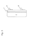
- Fig. 1 shows a vehicle 4, for example, a railway car, which has a magnetizable surface 3. It may be iron or any other ferromagnetic material. On the magnetizable surface, the holder 1 according to the invention is attached. This attachment can be done via any fasteners, such as screws, rivets, bolts or adhesives. In particular, it is provided that the holder 1 is firmly connected to the vehicle. Furthermore, a module 2 is shown, which is to be inserted into the holder 1. This is indicated by the dashed arrow. The insertion and release of the module 2 in and out of the holder 1 should be quick and easy and in the inserted state give the impression that the module 2 is firmly connected to the vehicle.
- the module is in particular a telematics module, for example an identification or location module.
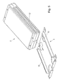
- Fig. 2 shows a three-dimensional view of a holder according to the invention 1.
- the holder 1 has recesses 5, which are designed such that they can accommodate magnets that are attached to the module to be used.
- the thickness of the holder can be selected so that the magnets disappear in the snapped state in the recesses 5 and are not visible from the outside.
- the holder 1 has second guide means 8 in the form of highly curved guide rails. These guide rails correspond to corresponding second guide means 7 in the module to be fastened.
- a stop 9 is provided which on the one hand further stabilizes the inserted module mechanically, and on the other hand prevents the view of the holding magnets.
- the stopper 9 has a recess 10 in order to give authorized persons the possibility of releasing the module 2 from the holder 1 by means of a correspondingly inserted tool.
- the holder 1 has tabs 14 with openings 11, which are designed as bores in the present embodiment and allow a screw connection of the holder to the vehicle.
- Fig. 3 shows a cross section through a module 2, which has a first guide means 7 in the form of a guide groove and holding magnets 6 at the bottom of the module.
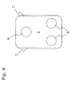
- Fig. 4 shows a view of the bottom of the module 2 with three magnets 5 and on the longitudinal sides of the first guide means 7, which are designed in the form of guide rails.
- the arrangement of the holding magnets 6 in the triangle ensures that the holding magnets 6 only snap into the recesses 5 when the module 2 is completely inserted into the holder 1.
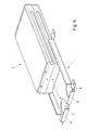
- FIGS. 5 to 7 show snapshots of the assembly process using the holder according to the invention.
- a first step Fig. 5
- the guide groove 12 of the module 2 is inserted into the guide rail 13 of the holder 1. This is indicated by the dashed arrow.
- the module 2 is pushed in the guide rail to the stop 9 ( Fig. 6 ).
- the holding magnets 6 snap into the recesses 5 and the state Fig. 7 occurs. In this locked state, the magnets are not visible from the outside.
- the inwardly projecting projection 15 of the guide rail 13 is narrower than the at least the thickness of the holding magnets 6 Width of the guide groove 12 in order to achieve that a corresponding clearance for snapping or releasing the holding magnets in the recesses is possible.
- the invention is not limited to the embodiments shown and in particular includes not only the holder itself, but also a module with fastening means which are designed for attachment to a holder according to the invention.
- the module used may comprise any component which is part of a larger system.
- the module may be a telematics module, an identification or location module.
Landscapes
- Engineering & Computer Science (AREA)
- Mechanical Engineering (AREA)
- Fittings On The Vehicle Exterior For Carrying Loads, And Devices For Holding Or Mounting Articles (AREA)
- Radar, Positioning & Navigation (AREA)
- Remote Sensing (AREA)
Abstract
Description
Die Erfindung betrifft eine Halterung zur lösbaren Befestigung eines Moduls an einer magnetisierbaren Fläche eines Fahrzeugs sowie ein Modul mit Befestigungsmitteln zur lösbaren Befestigung an einer derartigen Halterung.The invention relates to a holder for releasably securing a module to a magnetizable surface of a vehicle and a module with fastening means for releasable attachment to such a holder.
Im Bereich des Transportwesens und insbesondere im Bereich des Gütertransports auf Straße, Schiene, auf dem Wasser oder in der Luft ist es oft erforderlich, technische, austauschbare Module an den zu transportierenden Objekten anzubringen. Der Gütertransport kann insbesondere Container oder Eisenbahnwaggons umfassen. Bei den Modulen kann es sich insbesondere um Telematikmodule wie beispielsweise Identifikations- oder Ortungsmodule handeln.In the field of transport, and in particular in the field of goods transport by road, rail, on the water or in the air, it is often necessary to attach technical, interchangeable modules to the objects to be transported. The transport of goods may include in particular containers or railroad cars. The modules may in particular be telematic modules such as identification or locating modules.
Es ist insbesondere bekannt, Satellitenortungsmodule zur Ermittlung der Position von Eisenbahnwaggons an diesen Waggons anzubringen. Dies ermöglicht eine logistische Verfolgung und Ortung von Eisenbahnwaggons, was insbesondere in Hinblick auf die hohen durchschnittlichen Stehzeiten von Güterwaggons im europäischen Schienennetz von Bedeutung ist.It is known, in particular, to install satellite positioning modules for determining the position of railway carriages on these wagons. This allows logistical tracking and location of railway wagons, which is particularly important in view of the high average downtime of freight wagons in the European rail network.
Derartige Telematikmodule sind zum Teil aufwendig aufgebaut und dementsprechend teuer. Beispielsweise enthalten sie Elektronikschaltungen und Energieversorgungsvorrichtungen. Um Schäden durch Diebstahl oder Vandalismus in Grenzen zu halten, ist es erforderlich, die Module möglichst fest mit dem jeweiligen Fahrzeug zu verbinden. Andererseits muss jedoch gewährleistet sein, dass berechtigte Personen das Modul schnell und unkompliziert zu Auswertung, Tausch oder Wartung montieren oder demontieren können.Such telematics modules are sometimes complex and therefore expensive. For example, they include electronic circuits and power supply devices. In order to limit damage caused by theft or vandalism, it is necessary to connect the modules as firmly as possible to the respective vehicle. On the other hand, however, it must be ensured that authorized persons can quickly and easily assemble or disassemble the module for evaluation, replacement or maintenance.
Aus der
Auch aus der
Das Problem bei einer Befestigung des Moduls am Eisenbahnwaggon mittels Haftmagneten besteht nun darin, dass eine derartige Verbindung von nichtberechtigten Personen schnell gelöst werden kann. Auf der anderen Seite kann eine Verbindung mittels eines Klebstoffes von berechtigten Personen nicht ohne Weiteres bzw. ohne Beschädigung des Moduls gelöst werden.The problem with a mounting of the module on the railroad car by means of holding magnets is now that such a connection can be solved quickly by unauthorized persons. On the other hand, a connection by means of an adhesive by authorized persons can not be solved without further or without damaging the module.
Die technische Aufgabe der vorliegenden Erfindung besteht darin, eine Halterung für ein derartiges Modul vorzusehen, welche einerseits ein schnelles Anbringen und Lösen des Moduls am bzw. vom Fahrzeug erlaubt, und andererseits einen guten Schutz vor Diebstahl gewährleistet.
Diese Aufgabe wird erfindungsgemäß dadurch gelöst, dass die Halterung mindestens eine Aussparung zur Aufnahme mindestens eines Haftmagneten des Moduls umfasst.The technical object of the present invention is to provide a holder for such a module, which on the one hand allows a quick attachment and detachment of the module on or from the vehicle, and on the other hand ensures good protection against theft.
This object is achieved in that the holder comprises at least one recess for receiving at least one holding magnet of the module.
Die Halterung wird an einer magnetisierbaren Fläche des betreffenden Fahrzeugs befestigt und das, am Fahrzeug lösbar anzubringende Modul mit Haftmagneten wird derart in die Halterung eingeführt, dass die Haftmagnete in die entsprechende Aussparung der Halterung einschnappen. Dadurch wird erreicht, dass ein Verschieben des Moduls nicht möglich ist, und die Haftmagnete von außen nicht unmittelbar sichtbar sind.
Nicht berechtigten Personen wird der Eindruck vermittelt, dass das Modul unlösbar mit der Halterung und dem Fahrzeug verbunden ist. Darüber hinaus ist erfindungsgemäß vorgesehen, dass die Halterung mindestens ein, mit einem ersten Führungsmittel des Moduls korrespondierendes zweites Führungsmittel umfassen kann.The holder is attached to a magnetizable surface of the vehicle in question and the, releasably attached to the vehicle module with holding magnets is inserted into the holder such that the holding magnets snap into the corresponding recess of the holder. This ensures that a displacement of the module is not possible, and the magnets are not immediately visible from the outside.
Unauthorized persons are given the impression that the module is permanently connected to the bracket and the vehicle. In addition, the invention provides that the holder at least one, with a first Guide means of the module may comprise corresponding second guide means.
Derartige Führungsmittel können insbesondere in Form von Führungsschienen und damit korrespondierenden Führungsnuten ausgeführt sein. Beim Einführen des Moduls in die Halterung wird zunächst eine Führungsschiene in eine entsprechende Führungsnut eingeführt, wonach das Modul nur noch in eine Richtung beweglich ist.Such guide means may be designed in particular in the form of guide rails and thus corresponding guide grooves. When inserting the module in the holder, a guide rail is first inserted into a corresponding guide groove, after which the module is only movable in one direction.
Dann wird das Modul solange in die Halterung eingeschoben, bis die Haftmagnete in die entsprechende Aussparung der Halterung einschnappen, wodurch das Modul fest mit dem Fahrzeug verbunden ist. Eine Bewegung des Moduls ist damit so gut wie ausgeschlossen.Then the module is inserted into the holder until the holding magnets snap into the corresponding recess of the holder, whereby the module is firmly connected to the vehicle. A movement of the module is thus almost impossible.
Weiters kann erfindungsgemäß ein Anschlag zur mechanischen Stabilisierung des Moduls vorgesehen sein. Für den Fall, dass ein derartiger Anschlag vorgesehen ist, empfiehlt es sich, im Anschlag eine die Einführung eines zur Lösung der mechanischen Haltekraft geeigneten Werkzeugs erlaubende Aussparung vorzusehen. Berechtigte Personen können dann zunächst durch Einführung des geeigneten Werkzeugs die Magneten aus den Aussparungen lösen und durch gezielte Druckanwendung entlang der Führungsschiene das Modul aus der Halterung lösen.Furthermore, according to the invention a stop for mechanical stabilization of the module can be provided. In the event that such a stop is provided, it is advisable to provide in the stop a the introduction of a suitable solution for the mechanical holding force tool recess. Authorized persons can then first release the magnets from the recesses by introducing the appropriate tool and release the module from the holder by applying pressure along the guide rail.
Durch die Führungsmittel und/oder den Anschlag wird nicht berechtigten Personen der Blick auf die Haftmagnete verwehrt, wodurch der Eindruck entsteht, dass das Modul fest und unlösbar mit dem Fahrzeug verbunden ist.By the guide means and / or the attack unauthorized persons the view of the magnets is denied, creating the impression that the module is firmly and permanently connected to the vehicle.
Die Erfindung umfasst weiters auch das Modul selbst, sofern es mit Befestigungsmitteln zur Befestigung an einer erfindungsgemäßen Halterung ausgeführt ist.The invention further includes the module itself, if it is designed with fastening means for attachment to a holder according to the invention.
Weitere erfindungsgemäße Merkmale sind den Ansprüchen, der Beschreibung und den Figuren zu entnehmen.Further features according to the invention can be taken from the claims, the description and the figures.
Die Erfindung wird im folgenden anhand von Ausführungsbeispielen erklärt. Die
-
Fig. 1 : Ein Fahrzeug mit einer erfindungsgemäßen Halterung; -
Fig. 2 : Die erfindungsgemäße Halterung in dreidimensionaler Ansicht; -
Fig. 3 : Einen Querschnitt durch ein Modul zur Verwendung in der erfindungsgemäßen Halterung; -
Fig. 4 : Ansicht der Unterseite eines Moduls zur Verwendung in einer erfindungsgemäßen Halterung; -
Fig. 5 bis Fig. 7 : Zeigen den Ablauf des Einführens und Einrastens eines Moduls in eine erfindungsgemäße Halterung.
-
Fig. 1 : A vehicle with a holder according to the invention; -
Fig. 2 : The holder according to the invention in three-dimensional view; -
Fig. 3 : A cross section through a module for use in the holder according to the invention; -
Fig. 4 : View of the underside of a module for use in a holder according to the invention; -
Fig. 5 to Fig. 7 : Show the process of inserting and latching a module into a holder according to the invention.
Weiters verfügt die Halterung 1 über zweite Führungsmittel 8 in Form von hochgebogenen Führungsschienen. Diese Führungsschienen korrespondieren zu entsprechenden zweiten Führungsmitteln 7 in dem zu befestigenden Modul. Am Stirnende der Halterung 1 ist ein Anschlag 9 vorgesehen, der einerseits das eingesetzte Modul mechanisch weiter stabilisiert, und andererseits den Blick auf die Haftmagnete verhindert. Der Anschlag 9 verfügt über eine Aussparung 10, um berechtigten Personen die Möglichkeit zu geben, durch entsprechend einzusetzendes Werkzeug das Modul 2 von der Halterung 1 zu lösen.Furthermore, the
Weiters verfügt die Halterung 1 über Laschen 14 mit Öffnungen 11, die im vorliegende Ausführungsbeispiel als Bohrungen ausgeführt sind und eine Verschraubung der Halterung mit dem Fahrzeug erlauben.Furthermore, the
Die
In diesem Ausführungsbeispiel ist der nach innen ragende Vorsprung 15 der Führungsschiene 13 mindestens um die Dicke der Haftmagnete 6 schmäler ist als die Weite der Führungsnut 12, um zu erreichen, dass ein entsprechendes Spiel zum Einschnappen bzw. Lösen der Haftmagnete in die Aussparungen möglich ist.In this embodiment, the inwardly projecting
Die Erfindung beschränkt sich nicht auf die gezeigten Ausführungsbeispiele und umfasst insbesondere nicht nur die Halterung selbst, sondern auch ein Modul mit Befestigungsmitteln, welche zur Befestigung an einer erfindungsgemäßen Halterung ausgeführt sind. Das verwendete Modul kann jegliches Bauelement umfassen, welches Teil eines größeren Systems ist. Insbesondere kann es sich bei dem Modul um ein Telematikmodul, ein Identifikations- oder Ortungsmodul handeln.The invention is not limited to the embodiments shown and in particular includes not only the holder itself, but also a module with fastening means which are designed for attachment to a holder according to the invention. The module used may comprise any component which is part of a larger system. In particular, the module may be a telematics module, an identification or location module.
- 11
- Halterungbracket
- 22
- Modulmodule
- 33
- Magnetisierbare FlächeMagnetizable surface
- 44
- Fahrzeugvehicle
- 55
- Aussparungrecess
- 66
- HaftmagnetHolding magnet
- 77
- Erstes FührungsmittelFirst guide
- 88th
- Zweites FührungsmittelSecond guide
- 99
- Anschlagattack
- 1010
- Aussparungrecess
- 1111
- Öffnungopening
- 1212
- Führungsnutguide
- 1313
- Führungsschieneguide rail
- 1414
- Lascheflap
- 1515
- Vorsprunghead Start
Claims (10)
Applications Claiming Priority (1)
| Application Number | Priority Date | Filing Date | Title |
|---|---|---|---|
| AT14892010A AT510339B1 (en) | 2010-09-07 | 2010-09-07 | BRACKET |
Publications (1)
| Publication Number | Publication Date |
|---|---|
| EP2426014A1 true EP2426014A1 (en) | 2012-03-07 |
Family
ID=44508960
Family Applications (1)
| Application Number | Title | Priority Date | Filing Date |
|---|---|---|---|
| EP11178282A Withdrawn EP2426014A1 (en) | 2010-09-07 | 2011-08-22 | Mount |
Country Status (2)
| Country | Link |
|---|---|
| EP (1) | EP2426014A1 (en) |
| AT (1) | AT510339B1 (en) |
Cited By (2)
| Publication number | Priority date | Publication date | Assignee | Title |
|---|---|---|---|---|
| GB2510884A (en) * | 2013-02-15 | 2014-08-20 | Patrona Luggage Ltd | Mounting System |
| FR3129640A1 (en) * | 2021-11-26 | 2023-06-02 | Psa Automobiles Sa | Support intended for fixing a telematics module to an internal structural element of a motor vehicle, telematics system and vehicle comprising such a support |
Families Citing this family (1)
| Publication number | Priority date | Publication date | Assignee | Title |
|---|---|---|---|---|
| AT520216B1 (en) * | 2017-12-20 | 2019-02-15 | Lisa Maria Putz | Exchange license plate holder |
Citations (5)
| Publication number | Priority date | Publication date | Assignee | Title |
|---|---|---|---|---|
| WO2000049919A1 (en) * | 1999-02-26 | 2000-08-31 | Dash-It Usa Inc. | Magnetic coupler and various embodiments thereof |
| WO2002095438A2 (en) | 2001-05-22 | 2002-11-28 | Geospatial Technologies, Inc. | A durable global asset-tracking device and a method of using the same |
| DE202006003665U1 (en) * | 2006-03-08 | 2006-06-01 | Jentro Technologies Gmbh | Fastening for portable equipment, has first fastening part and second fastening part whereby first fastening part is integrated into housing part of portable equipment |
| EP1950094A2 (en) * | 2007-01-26 | 2008-07-30 | Harman Becker Automotive Systems GmbH | A system for mounting a mobile electronic device |
| AT502346B1 (en) | 2005-09-08 | 2008-12-15 | Tarter Philipp Dipl Ing | TRACKING DEVICE |
Family Cites Families (1)
| Publication number | Priority date | Publication date | Assignee | Title |
|---|---|---|---|---|
| FR2840751A1 (en) * | 2002-06-07 | 2003-12-12 | Franck Daniel Edmond Letinois | Mobile telephone/remote control surface attachment method having circular metallic disc with central protrusion attached mobile telephone and metallic magnetic disc with central hole wall/plastic surface attached |
-
2010
- 2010-09-07 AT AT14892010A patent/AT510339B1/en not_active IP Right Cessation
-
2011
- 2011-08-22 EP EP11178282A patent/EP2426014A1/en not_active Withdrawn
Patent Citations (5)
| Publication number | Priority date | Publication date | Assignee | Title |
|---|---|---|---|---|
| WO2000049919A1 (en) * | 1999-02-26 | 2000-08-31 | Dash-It Usa Inc. | Magnetic coupler and various embodiments thereof |
| WO2002095438A2 (en) | 2001-05-22 | 2002-11-28 | Geospatial Technologies, Inc. | A durable global asset-tracking device and a method of using the same |
| AT502346B1 (en) | 2005-09-08 | 2008-12-15 | Tarter Philipp Dipl Ing | TRACKING DEVICE |
| DE202006003665U1 (en) * | 2006-03-08 | 2006-06-01 | Jentro Technologies Gmbh | Fastening for portable equipment, has first fastening part and second fastening part whereby first fastening part is integrated into housing part of portable equipment |
| EP1950094A2 (en) * | 2007-01-26 | 2008-07-30 | Harman Becker Automotive Systems GmbH | A system for mounting a mobile electronic device |
Cited By (2)
| Publication number | Priority date | Publication date | Assignee | Title |
|---|---|---|---|---|
| GB2510884A (en) * | 2013-02-15 | 2014-08-20 | Patrona Luggage Ltd | Mounting System |
| FR3129640A1 (en) * | 2021-11-26 | 2023-06-02 | Psa Automobiles Sa | Support intended for fixing a telematics module to an internal structural element of a motor vehicle, telematics system and vehicle comprising such a support |
Also Published As
| Publication number | Publication date |
|---|---|
| AT510339A1 (en) | 2012-03-15 |
| AT510339B1 (en) | 2014-04-15 |
Similar Documents
| Publication | Publication Date | Title |
|---|---|---|
| EP2819885B1 (en) | Retaining frame for sensor devices in vehicles | |
| DE102011009683A1 (en) | Method for mounting a component and fastening clip | |
| DE102010039136A1 (en) | Device for holding systems and aircraft or spacecraft | |
| DE102013216555A1 (en) | Fastening device for a battery in a motor vehicle | |
| DE102010000596A1 (en) | Conveying device for conveying objects | |
| AT510339B1 (en) | BRACKET | |
| DE102013100909B3 (en) | Electrical installation device e.g. switch, has recess acting together with sliding piece comprising multi-stage internal tooth that act together with multi-stage external tooth of holding element, where holding element is fixed to support | |
| EP1398219A2 (en) | Device for accommodating an electrical apparatus in a vehicle compartment | |
| DE102013223358B4 (en) | Device for attaching a decorative strip to a vehicle outer skin element, trim strip and vehicle outer skin element | |
| DE202009012024U1 (en) | Information or advertising medium | |
| DE102014213662A1 (en) | Arrangement and method for attaching trim parts to a substructure | |
| EP3020904B1 (en) | Covering device for covering a roller track surface of a sliding door system | |
| CH701612A2 (en) | Exchange plate holder for vehicle license | |
| DE10253177A1 (en) | System for attaching flat plastic components to car bodywork comprises rectangular bolt which is inserted into slot in component, transverse ribs on bolt sides allowing it to snap into slot at different heights | |
| DE102013011536A1 (en) | Positioning device and method for adhering an object to a surface | |
| EP1693252A1 (en) | Mounting mechanism | |
| AT508607B1 (en) | REPLACEMENT HOLDER FOR VEHICLE MARKINGS | |
| DE102012006779A1 (en) | Coupling aid with anti-theft device | |
| DE102017130069B4 (en) | Cradle, fastening element, fastening system, extractor hood, filter and extractor hood system | |
| DE102010044536B4 (en) | plate holder | |
| EP3369861A1 (en) | Device for arranging a train securing component in a track area | |
| DE102017113899B4 (en) | Guide means for fixing an object in a rail, system comprising such a guide means and a rail for receiving a guide means, and method for producing the guide means | |
| DE102017008947B4 (en) | FASTENING SYSTEM FOR SECURING A COMPONENT TO A VEHICLE FRAME | |
| EP2881596A1 (en) | Mounting wedge | |
| DE102010009282A1 (en) | Device for tool-less fastening of car number plate, has fastening arrangement provided with biasing spring for compensation of thickness tolerances, where one of brackets of arrangement is moved against return force in direction of brackets |
Legal Events
| Date | Code | Title | Description |
|---|---|---|---|
| AK | Designated contracting states |
Kind code of ref document: A1 Designated state(s): AL AT BE BG CH CY CZ DE DK EE ES FI FR GB GR HR HU IE IS IT LI LT LU LV MC MK MT NL NO PL PT RO RS SE SI SK SM TR |
|
| AX | Request for extension of the european patent |
Extension state: BA ME |
|
| PUAI | Public reference made under article 153(3) epc to a published international application that has entered the european phase |
Free format text: ORIGINAL CODE: 0009012 |
|
| 17P | Request for examination filed |
Effective date: 20120828 |
|
| 17Q | First examination report despatched |
Effective date: 20140224 |
|
| STAA | Information on the status of an ep patent application or granted ep patent |
Free format text: STATUS: THE APPLICATION IS DEEMED TO BE WITHDRAWN |
|
| 18D | Application deemed to be withdrawn |
Effective date: 20140708 |