EP2425705B1 - Dispositif de coupe - Google Patents
Dispositif de coupe Download PDFInfo
- Publication number
- EP2425705B1 EP2425705B1 EP11170854.1A EP11170854A EP2425705B1 EP 2425705 B1 EP2425705 B1 EP 2425705B1 EP 11170854 A EP11170854 A EP 11170854A EP 2425705 B1 EP2425705 B1 EP 2425705B1
- Authority
- EP
- European Patent Office
- Prior art keywords
- cutting
- adjusting
- cutting tool
- counterpart
- cutting member
- Prior art date
- Legal status (The legal status is an assumption and is not a legal conclusion. Google has not performed a legal analysis and makes no representation as to the accuracy of the status listed.)
- Active
Links
Images

Classifications
-
- A—HUMAN NECESSITIES
- A01—AGRICULTURE; FORESTRY; ANIMAL HUSBANDRY; HUNTING; TRAPPING; FISHING
- A01F—PROCESSING OF HARVESTED PRODUCE; HAY OR STRAW PRESSES; DEVICES FOR STORING AGRICULTURAL OR HORTICULTURAL PRODUCE
- A01F29/00—Cutting apparatus specially adapted for cutting hay, straw or the like
- A01F29/09—Details
- A01F29/095—Mounting or adjusting of knives
-
- A—HUMAN NECESSITIES
- A01—AGRICULTURE; FORESTRY; ANIMAL HUSBANDRY; HUNTING; TRAPPING; FISHING
- A01D—HARVESTING; MOWING
- A01D34/00—Mowers; Mowing apparatus of harvesters
- A01D34/01—Mowers; Mowing apparatus of harvesters characterised by features relating to the type of cutting apparatus
- A01D34/412—Mowers; Mowing apparatus of harvesters characterised by features relating to the type of cutting apparatus having rotating cutters
- A01D34/42—Mowers; Mowing apparatus of harvesters characterised by features relating to the type of cutting apparatus having rotating cutters having cutters rotating about a horizontal axis, e.g. cutting-cylinders
- A01D34/62—Other details
Definitions
- the invention relates to a cutting device for crop according to the preamble of claim 1.
- the invention relates to a method for adjusting the counter-blade of a cutting device according to the preamble of claim 13.
- Agricultural harvesting machines in particular forage harvesters, have a cutting device which comprises a cutting tool designed as a knife drum, which rotates relative to a stationary counter-cutting edge. Crop material, which gets into an engagement region formed by the rotating cutterhead and counter-cutting edge, is comminuted, in particular chopped, by interaction of the cutting blades fastened to the rotating cutterhead with the counter-cutting edge.
- the knife drum is therefore also referred to as a chopper drum.
- the cutting blades wear off during operation. Therefore, they are reground repeatedly, on the one hand to achieve a consistent quality cut, on the other hand to keep the cutting forces and thus the expended for the chopping drive energy low.
- a precise and energy-efficient chopping process can only be carried out if - in addition to the knife sharpness - there is also a certain distance between the counterblade and the cutting tool. Too long a distance leads to partly incomplete cut of the incoming material and can be applied to the cutting forces increase. Too small a distance in particular involves the risk that the cutting blade and the counter-blade touch, which can lead to material damage or even dangerous detachment of material and / or machine elements.
- a distance determination or at least estimation is essential. This is done in practice by approaching the counter-blade on the rotating cutting tool until a contact takes place, which can be seen for example on the basis of so-called “knocking”, which can be detected in particular by so-called “knock sensors”, which are attached to the counter-blade Vibration sensors act.
- a method with a corresponding purpose should be specified.
- the end of the counter-blade moved in each case by the adjusting device approaches the cutting tool by a defined travel with each of the alternating steps. This is done by forward and backward movement of the respective activated side, wherein the forward movement is greater than the backward movement, so that a forward movement results.
- the invention there is the advantage, compared to a pure forward movement, that mechanical stresses on the counter-blade and the respective adjusting device are reduced during each working step.
- the counter-blade is clamped relatively stiff due to high forces acting thereon.
- the control device initially performs a control of the adjustment before starting the approach to move the counter-blade away from the cutting tool.
- their bearings are freely movable, which favors a precise approach.
- the cutting device comprises at least one sensor, which is suitable for detecting a contact of counter cutting edge and cutting tool, wherein the control device controls the adjusting devices in response to received signals of this sensor.
- a knock sensor for example, is a knock sensor, an impact sensor or another acoustic sensor.
- This can be arranged on the counter-blade itself to detect structure-borne vibrations of the counter-blade.
- Several such sensors can be arranged at different positions to ensure a more secure or more accurate detection.
- the use of at least one sensor is conceivable, which is suitable for detecting the achievement of a minimum distance between the counter-blade and cutting tool, wherein the control device controls the adjusting devices in response to received signals of this sensor.
- the sensor does not detect a contact between the counterknife and the cutting tool, but recognizes a minimum distance between them, based on suitable circumstances.
- the sensor could detect, for example, air vibrations (sound), to which the rotating cutting tool excites the counter-blade from reaching a certain distance position.
- Other non-contact types of recognition eg optical are conceivable.
- the respectively activated adjusting leads in the case of a detected by the sensor touch or reaching a minimum distance during a working adjustment of its associated end of the bedknife additionally by a third adjustment distance from the cutting tool through, the second and third Spacing together are larger than the first range.
- Such an adjustment ensures that the counter-blade advantageously aligns substantially parallel to the cutting tool by the side of the counter-blade, on which is assumed to touch or reaching a minimum distance due to the sensor signal during the adjustment, is moved away from the cutting tool. The problem of using previous Sensorics difficult page assignment of sensor signals is thus bypassed constructively.
- control device causes the alternating activation of the adjusting devices until the sensor has detected in each case two consecutive working steps a touch or a minimum distance relative to the cutting tool.
- the adjustment provided according to the invention can be advantageously realized by assigning a measuring device to each side of the counter-blade which is suitable for detecting a variable corresponding to the adjustment path of the respective side.
- a measuring device may be incremental encoders.
- each of the adjusting devices can adjust the end of the counter-blade assigned to it by defined positioning widths in front of or behind with respect to the cutting tool.
- the cutting device comprises a starting device, wherein by triggering the starting device, the control device executes a program for setting a counter-cutting distance determinable in the program.
- the setting in accordance with a program running in the control device offers the advantage that measures to be taken for the adjustment of the counter-blade spacing and conditions to be fulfilled can be integrated flexibly therein.
- the alternating activation of the adjusting devices can begin with an activation of those of the two adjusting devices, which according to a signal of their associated measuring device has a smaller distance relative to the cutting tool.
- control device is expediently operable to move the counter-blade from an initial position found by approaching the cutting tool by actuating the adjusting devices into an operating position which has a definable distance from the starting position.
- a distance may, for example, be variably stored in a program executed by the control device.
- the program compares the execution of the steps for approaching the bedknife to the cutting tool, the pitch of the adjusting and causes when exceeding a definable in the program difference of the pitches a repetition of the adjustment process.
- the cutting device described is particularly suitable for use as a working member of an agricultural harvester.
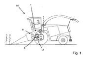
- Fig. 1 shows an example of a forage harvester 10.
- the forage harvester 10 is designed as a self-propelled harvester with front and rear axles and is suitable for driving over a field to harvest indicated plant stock.
- the forage harvester 10 cuts off the crop from the field by means of an unspecified header and feeds it to a feeder 11 which, inter alia, comprises two pairs of pre-press rollers which compact the harvested crop.
- the harvested material is fed to a cutting device 1 ("chopping unit"), which essentially comprises a rotating cutterhead 2 and a counterblade 3 resting against it.
- a cutting device 1 (“chopping unit"), which essentially comprises a rotating cutterhead 2 and a counterblade 3 resting against it.
- a cutting device 1 "chopping unit"
- This cutting device 1 are in connection with the Fig. 2 and 3 explained in more detail.
- the crop is crushed, to be subsequently ejected from the forage harvester 10 via a conveyor shaft ascending behind a driver's
- the cutterhead 2 is provided with a plurality of (in Fig. 1 not designated) knives fitted and rotates in the harvesting operation as shown in Fig. 1 counterclockwise to cut in cooperation with the resting counter-blade 3 crop, which is promoted by the intake member 11 as a pre-pressed Erntegutmatte in the direction of the cutting device 1.
- the invention relates to an apparatus and a method that allow better adjustability of this distance.
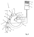
- Fig. 2 and 3 show an embodiment of a cutting device 1 according to the invention in a schematic side view and according to the section line AA in half section from the front.
- the half-section according to Fig. 3 is with respect to the dashed line in the right part of the image in mirror image to complete a full view.
- the cutting device 1 according to Fig. 2 and 3 comes in an advantageous way as in Fig. 1 described forage harvester 10 is used.
- the cutting device 1 shown essentially comprises a rotatable about an axis of rotation 13 cutterhead 2 and one of the cutterhead 2 with respect to adjustable counter-blade 3.
- a fixed to the cutterhead 2 cutting blade 12 is located, which belongs to a plurality of further circumferentially distributed (not shown) cutting blade.
- the cutting blades 12 sweep the in Fig. 2
- the radius of this enveloping circle is influenced by the grinding state of the cutting blade 12.
- the counter-blade 3 essentially comprises a counter-cutting carrier 15, on which a counter-cutting bar 14 is mounted, for example screwed.
- the counter-cutting support 15 is supported via rod ends 16 with respect to a frame-fixed cross member 17. Accordingly, the counter-blade 3 is pivotable about a hinge axis 25 parallel to the rotation axis 13, wherein the distance position of the counter-cutting beam 14 relative to the cutterhead 2 can be changed by pivoting the counter-blade 3.
- the counter-cutting support 15 has a wider width.
- each serve as a knock sensor vibration sensor 7 is attached to both side end portions.
- Fig. 2 a side view is and Fig. 3 the cutting device 1 only in half section, only one of the vibration sensors 7 is visible in each case.
- each of the vibration sensors 7 is connected via a cable to a control device 6, which preferably contains a microprocessor for data processing and is suitable for executing freely programmable work programs.
- Fig. 2 and 3 show that the lateral ends of the counter-blade 3 are respectively coupled to an adjusting device 4 and 5, wherein Fig. 2 the adjusting device 4 shows and in Fig. 3 because of the different view perspective, the opposite adjustment 5 shows, which structurally corresponds to the adjusting device 4.
- the distance position of the counter-blade 3 relative to the cutterhead 2 can be changed.
- the lever arm 18 is equipped with a friction brake 22.
- the lever arm 18 is therefore within the predetermined by the passage clearance relative to the frame-fixed housing wall 24 movable to perform adjustment movements of the counter-blade 3 can.
- the lever arm 18 - and thus the entire counter-blade 3 - can be adjusted via a helical gear, which is driven by a frame-mounted motor 21.
- the output axis of the motor 21 is designed as a threaded spindle 19, which engages in a remote from the counter-blade 15 end of the lever arm 18 mounted spindle nut 20. Accordingly, rotation of the output shaft of the motor 21 causes pivoting of the counter blade 3.
- the adjusting devices 4 and 5 have mutually independently operable motors 21 on both sides of the counter-blade 3, a lateral adjustment of the counter-blade 3 is possible. Due to the statically overdetermined bearing of the counter-blade 3, the lateral adjustment leads to tension of the components involved, under the counter-blade 3 can deform.
- a control device 6 controls the motors 21 via a signal line.
- the control device 6 is connected to vibration sensors 7, which are suitable for detecting a contact of counter blade 3 and blade drum 2, as well as with incremental encoders 8, which are respectively assigned to the motors 21 and for detecting adjustment ranges of the respective adjustment 4 and 5 are suitable.
- the control device 6 is connected to the signal exchange with an operating device 9, which is advantageously associated with a display 23.
- the Operating device 9 and the display 23 arranged in a driver's cab of the forage harvester 10 to be operated by a machine operator or to be able to display the operator information regarding the adjustment process.
- An adjustment of the counter-blade 3 proceeds as follows. After a successful grinding operation of the cutting blade 12, the distance between the effective cutting edge of the cutterhead 2 and counter-blade 3 has changed and is initially unknown. In order to set a desired distance between the counterblade 3 and the cutterhead 2 (for example, for the harvesting operation), a machine operator actuates a starting device provided on the operating device 9. As a result, the control device 6 executes a program for setting the counter cutting distance.
- the adjustment process comprises a low-tension approach of the counter-blade 3 to the cutterhead 2.
- the control device 6 activates the adjusting devices 4 or 5 for carrying out one working step alternately.
- the control device 6 causes that of the adjusting device 4 or 5 starts to approach, which has a smaller distance relative to the cutterhead 2 in accordance with a position signal of its associated incremental encoder 8.
- the incremental encoders 8 may, for example, comprise pulse generators, so that the page with the smaller pulse position begins with the setting process.
- the now alternately carried out steps include that the respective activated adjusting 4 or 5 moves the end of the counter-blade 3 associated with it first by a first set width to the cutterhead 2 out and then by a second setting again from the cutterhead 2 away, the second setting smaller is considered the first range.
- the first setting width is about twice as large as the second setting width.
- the control device 6 monitors by means of the vibration sensors 7 ("knock sensors"), whether during the execution of the individual steps, the counter-blade 3 touches the rotating during the adjustment blade drum 2.
- the respectively executed work step is modified by the control device 6 activates the respectively activated adjusting 4 or 5 such that the adjusting device 4 or 5, the side of the counter-blade 3 associated with it after reset by the second setting width in addition to a third setting of the cutterhead 2 moves away, wherein the second and third adjustment width together are greater than the first setting width.
- Such a work step in which a collision with the cutterhead 2 has been detected, effectively leads to a return of the active side of the counter-blade 3 from the cutterhead 2 away.
- the positioning ranges of the adjusting devices 4, 5 detected by the incremental encoder 8 are compared in the program and if exceeded a difference in the ranges that can be defined in the program causes a repetition of the entire setting process.
- the control device 6 can finally move the counter-blade 3 by actuating the motors 21 into a desired operating position for the harvesting operation, which from the starting position has a fixable by the operator in the running program distance.
- the control device 6 monitors the running of the motors 21 via the respective incremental encoders 8, so that an accurate positioning is possible.
- the starting of the operating position by the motors 21 takes place alternately in small steps in order to avoid tensioning of the counter-blade 3 or of the adjusting devices 4, 5.
Landscapes
- Life Sciences & Earth Sciences (AREA)
- Environmental Sciences (AREA)
- Harvester Elements (AREA)
- Details Of Cutting Devices (AREA)
- Finish Polishing, Edge Sharpening, And Grinding By Specific Grinding Devices (AREA)
Claims (13)
- Dispositif de coupe (1) de produit de récolte, comprenant un outil de coupe (2) pouvant être mis en rotation et un contre-couteau (3) qui est réglable par rapport à celui-ci et dont les deux extrémités opposées sont chacune reliées à un dispositif de réglage (4, 5), de sorte que l'écartement du contre-couteau (3) par rapport à l'outil de coupe (2) est variable, un dispositif de commande (6) actionnant les dispositifs de réglage (4, 5) pour modifier l'écartement du contre-couteau (3), caractérisé en ce que, pour rapprocher le contre-couteau (3) de l'outil de coupe (2), le dispositif de commande (6) peut être actionné de façon qu'avant le début du rapprochement le dispositif de commande (6) procède d'abord à un actionnement des dispositifs de réglage (4, 5) afin d'éloigner le contre-couteau (3) de l'outil de coupe (2) et d'activer ensuite les dispositifs de réglage (4, 5) en alternance pour réaliser à chaque fois une étape de travail, à l'intérieur de cette étape de travail le dispositif de réglage respectif activé (4, 5) réalisant un déplacement de l'extrémité du contre-couteau (3) qui lui est associée, d'abord selon une première distance de réglage en direction de l'outil de coupe (2) et ensuite selon une deuxième distance de réglage en l'éloignant à nouveau de l'outil de coupe (2), la deuxième distance de réglage étant inférieure à la première distance de réglage, le rapprochement mutuel uniforme permettant de donner au contre-couteau (3) une orientation en très grande partie parallèle à l'outil de coupe (2), de sorte que l'exécution réciproque de ces étapes de travail par actionnement des deux dispositifs de réglage (4 et 5) conduit à un rapprochement pas à pas du contre-couteau (3) par rapport à l'outil de coupe (2).
- Dispositif de coupe selon la revendication 1, caractérisé en ce qu'il est prévu au moins un capteur (7) apte à détecter un contact entre le contre-couteau (3) et l'outil de coupe (2), le dispositif de commande (6) actionnant les dispositifs de réglage (4, 5) en fonction de signaux reçus du capteur (7).
- Dispositif de coupe selon la revendication 1 ou 2, caractérisé en ce qu'il est prévu au moins un capteur apte à détecter l'atteinte d'un écartement minimal entre le contre-couteau (3) et l'outil de coupe (2), le dispositif de commande (6) actionnant les dispositifs de réglage (4, 5) en fonction de signaux reçus du capteur.
- Dispositif de coupe selon la revendication 2 ou 3, caractérisé en ce qu'en cas de contact détecté par le capteur (7) ou d'atteinte d'un écartement minimal durant une étape de travail le dispositif de réglage respectif activé (4, 5) effectue un déplacement supplémentaire de l'extrémité du contre-couteau (3) qui lui est associée, selon une troisième distance de réglage en l'éloignant de l'outil de coupe (2), les deuxième et troisième distances de réglage cumulées étant supérieures à la première distance de réglage.
- Dispositif de coupe selon une des revendications 1 à 4, caractérisé en ce que le dispositif de commande (6) provoque l'activation alternée des dispositifs de réglage (4, 5) jusqu'à ce que le capteur (7) ait détecté dans deux étapes de travail successives un contact ou un écartement minimal par rapport à l'outil de coupe (2).
- Dispositif de coupe selon une des revendications 1 à 5, caractérisé en ce qu'à chaque côté du contre-couteau (3) est associé un dispositif de mesure (8) apte à enregistrer une grandeur correspondant à la course de réglage du côté en question.
- Dispositif de coupe selon une des revendications 1 à 6, caractérisé par un dispositif de lancement (9), le dispositif de commande (6) exécutant, en cas de déclenchement du dispositif de lancement (9), un programme pour régler un écartement, définissable dans le programme, du contre-couteau (3) par rapport à l'outil de coupe (2).
- Dispositif de coupe selon une des revendications 1 à 7, caractérisé en ce que l'activation alternée des dispositifs de réglage (4, 5) commence par une activation de celui des deux dispositifs de réglage (4, 5) qui, selon un signal du dispositif de mesure (8) qui lui est associé, présente le plus faible écart par rapport à l'outil de coupe (2).
- Dispositif de coupe selon une des revendications 1 à 8, caractérisé en ce que le dispositif de commande (6) peut être actionné de façon que le contre-couteau (3) soit déplacé, par actionnement des dispositifs de réglage (4, 5), d'une position de départ atteinte après rapprochement par rapport à l'outil de coupe (2) vers une position de fonctionnement présentant un écartement définissable par rapport à la position de départ.
- Dispositif de coupe selon une des revendications 1 à 9, caractérisé en ce qu'avant de réaliser les étapes de travail visant à rapprocher le contre-couteau (3) de l'outil de coupe (2) le programme prévoit d'abord d'actionner les dispositifs de réglage (4, 5) pour éloigner le contre-couteau (3) de l'outil de coupe (2).
- Dispositif de coupe selon une des revendications 1 à 10, caractérisé en ce qu'à l'issue des étapes de travail visant à rapprocher le contre-couteau (3) de l'outil de coupe (2) le programme compare les distances de réglage des dispositifs de réglage (4, 5) et, en cas de surpassement d'une différence entre les distances de réglage définissable dans le programme, provoque une répétition de l'opération de réglage.
- Dispositif de coupe selon une des revendications 1 à 11, caractérisé en ce que celui-ci est un organe de travail d'une machine agricole de récolte (10).
- Procédé de réglage du contre-couteau (3) d'un dispositif de coupe de produit de récolte, en particulier d'un dispositif de coupe (1) selon une des revendications précédentes, le dispositif de coupe (1) comprenant un outil de coupe (2) pouvant être mis en rotation et un contre-couteau (3) qui est réglable par rapport à celui-ci et dont les deux extrémités opposées sont chacune reliées à un dispositif de réglage (4, 5), de sorte que l'écartement du contre-couteau (3) par rapport à l'outil de coupe (2) est variable, caractérisé en ce que le contre-couteau (3) est d'abord éloigné de l'outil de coupe (2) selon une distance de réglage déterminée au moyen des deux dispositifs de réglage (4 et 5) et en ce qu'ensuite, pour rapprocher le contre-couteau (3) de l'outil de coupe (2), les dispositifs de réglage (4, 5) sont activés en alternance pour réaliser chacun une étape de travail, à l'intérieur d'une étape de travail le dispositif de réglage respectif activé (4, 5) réalisant un déplacement de l'extrémité du contre-couteau (3) qui lui est associée, d'abord selon une première distance de réglage en direction de l'outil de coupe (2) et ensuite selon une deuxième distance de réglage en l'éloignant à nouveau de l'outil de coupe (2), la deuxième distance de réglage étant inférieure à la première distance de réglage, le rapprochement mutuel uniforme permettant de donner au contre-couteau (3) une orientation en très grande partie parallèle à l'outil de coupe (2), de sorte que l'exécution réciproque de ces étapes de travail par actionnement des deux dispositifs de réglage (4 et 5) conduit à un rapprochement pas à pas du contre-couteau (3) par rapport à l'outil de coupe (2).
Applications Claiming Priority (1)
| Application Number | Priority Date | Filing Date | Title |
|---|---|---|---|
| DE102010037358A DE102010037358A1 (de) | 2010-09-07 | 2010-09-07 | Schneidvorrichtung |
Publications (2)
| Publication Number | Publication Date |
|---|---|
| EP2425705A1 EP2425705A1 (fr) | 2012-03-07 |
| EP2425705B1 true EP2425705B1 (fr) | 2016-01-06 |
Family
ID=44802577
Family Applications (1)
| Application Number | Title | Priority Date | Filing Date |
|---|---|---|---|
| EP11170854.1A Active EP2425705B1 (fr) | 2010-09-07 | 2011-06-22 | Dispositif de coupe |
Country Status (4)
| Country | Link |
|---|---|
| US (1) | US8250842B2 (fr) |
| EP (1) | EP2425705B1 (fr) |
| DE (1) | DE102010037358A1 (fr) |
| RU (1) | RU2497346C2 (fr) |
Families Citing this family (9)
| Publication number | Priority date | Publication date | Assignee | Title |
|---|---|---|---|---|
| DE102011052726A1 (de) * | 2011-08-16 | 2013-02-21 | Claas Selbstfahrende Erntemaschinen Gmbh | Verfahren und Vorrichtung zur Zustandserkennung einer Schneideinrichtung |
| DE102013201633B3 (de) * | 2013-01-31 | 2014-03-27 | Deere & Company | Einrichtung zur Verstellung der Position einer Gegenschneide gegenüber einer Häckseleinrichtung |
| DE102013101183A1 (de) * | 2013-02-07 | 2014-08-07 | Claas Selbstfahrende Erntemaschinen Gmbh | Landwirtschaftliche Arbeitsmaschine, insbesondere Feldhäcksler |
| DE102017008126A1 (de) * | 2017-08-30 | 2019-02-28 | Müthing GmbH & Co. KG | Landwirtschaftliche Arbeitsvorrichtung |
| US11617304B2 (en) * | 2019-10-25 | 2023-04-04 | Cnh Industrial America Llc | Staggered harvester head reel position adjustment |
| US11570951B2 (en) * | 2019-12-19 | 2023-02-07 | Deere & Company | Forage harvester with processing component protection |
| DE102020110470A1 (de) | 2020-04-17 | 2021-10-21 | Glaß & Wolff Metalltechnik GmbH & Co. KG | Schleifvorrichtung zum Schleifen von Schneideinheiten und Aufbereitungsanlage zum Aufbereiten von gebrauchten Schneideinheiten |
| CN112005741A (zh) * | 2020-09-04 | 2020-12-01 | 中国铁建重工集团股份有限公司 | 一种青贮收获机及其动定刀间隙调节装置 |
| GB202020465D0 (en) * | 2020-12-23 | 2021-02-03 | Agco Int Gmbh | Forage harvester |
Family Cites Families (24)
| Publication number | Priority date | Publication date | Assignee | Title |
|---|---|---|---|---|
| US4516388A (en) * | 1979-09-12 | 1985-05-14 | Chandler Noel W | Hydraulic bedknife adjuster for reel-type mowing equipment |
| DE3010416A1 (de) * | 1980-03-19 | 1981-09-24 | Claas Ohg, 4834 Harsewinkel | Vorrichtung zur ueberwachung des schneidenabstans an erntemaschinen |
| US4479346A (en) * | 1981-03-31 | 1984-10-30 | Noel Chandler | Automatic electrical bed knife adjuster |
| US4412212A (en) * | 1981-08-10 | 1983-10-25 | Deere & Company | Shearbar clearance detector |
| IT1169382B (it) * | 1982-12-20 | 1987-05-27 | Hesston Corp | Meccanismo di regolazione automatica della barra di tranciamento azionato da motore di una mietitrice |
| US4663924A (en) * | 1985-09-27 | 1987-05-12 | Textron Inc. | Apparatus and method for establishing reel-to-bedknife clearance |
| US4653256A (en) * | 1985-11-15 | 1987-03-31 | Textron Inc. | Apparatus for establishing reel-to-bedknife clearance |
| US4799625A (en) | 1987-05-05 | 1989-01-24 | Ford New Holland, Inc. | Method and apparatus for adjusting a shear bar relative to a cutter head |
| US4934612A (en) * | 1988-03-28 | 1990-06-19 | Deere & Company | Automatic forage harvester shearbar adjusting |
| SU1724080A1 (ru) * | 1989-11-09 | 1992-04-07 | Днепропетровский сельскохозяйственный институт | Измельчитель кормов |
| US5018342A (en) * | 1990-04-13 | 1991-05-28 | Ford New Holland, Inc. | Method for shear bar adjustment in a forage harvester |
| US5083976A (en) * | 1990-10-26 | 1992-01-28 | Ford New Holland, Inc. | Adjustment of a shear bar using an air-borne sound detector |
| GB2299256A (en) * | 1995-03-31 | 1996-10-02 | Ford New Holland Nv | Forage harvester cutting apparatus |
| DE19716183A1 (de) * | 1997-04-18 | 1998-10-22 | Tekbilt Inc | Verfahren und Vorrichtung zur Abstandsmessung bei Landmaschinen |
| US6044637A (en) * | 1998-01-30 | 2000-04-04 | Deere & Company | Bedknife adjustment linkage |
| DE10235919B4 (de) * | 2002-07-30 | 2006-02-09 | Deere & Company, Moline | Verfahren und Anordnung zur Bestimmung der Schärfe von Häckselmessern |
| US7121073B2 (en) * | 2003-04-30 | 2006-10-17 | Deere & Company | Cutting reel adjusting system |
| US7231757B2 (en) * | 2003-04-30 | 2007-06-19 | Deere & Company | Method and apparatus for setting and maintaining reel-to-bedknife clearance |
| US7788892B2 (en) * | 2003-07-10 | 2010-09-07 | Deere & Company | User interface and control for cutting reel system |
| DE10346412A1 (de) * | 2003-10-07 | 2005-05-25 | Deere & Company, Moline | Erntemaschine mit einer Überwachungseinrichtung zur Überwachung der Schärfe von Schneidmessern und/oder ihres Abstands zu einer Gegenschneide |
| DE102004016089B4 (de) * | 2004-04-01 | 2012-12-06 | Deere & Company | Einrichtung zur Verstellung der Position einer Gegenschneide gegenüber einer Häckseleinrichtung |
| US7353644B2 (en) * | 2006-03-29 | 2008-04-08 | Deere & Company | Method for adjusting reel-to-bedknife clearance |
| US7370461B2 (en) * | 2006-03-29 | 2008-05-13 | Deere & Company | Adaptive threshold technique for detecting reel-to-bedknife contact |
| US7631479B2 (en) * | 2007-10-23 | 2009-12-15 | Deere & Company | Adjustable pivot axis for bedknife assembly |
-
2010
- 2010-09-07 DE DE102010037358A patent/DE102010037358A1/de not_active Withdrawn
-
2011
- 2011-06-22 EP EP11170854.1A patent/EP2425705B1/fr active Active
- 2011-08-23 US US13/215,361 patent/US8250842B2/en active Active
- 2011-09-05 RU RU2011136552/13A patent/RU2497346C2/ru active
Also Published As
| Publication number | Publication date |
|---|---|
| EP2425705A1 (fr) | 2012-03-07 |
| DE102010037358A1 (de) | 2012-03-08 |
| RU2011136552A (ru) | 2013-03-10 |
| US20120055135A1 (en) | 2012-03-08 |
| RU2497346C2 (ru) | 2013-11-10 |
| US8250842B2 (en) | 2012-08-28 |
Similar Documents
| Publication | Publication Date | Title |
|---|---|---|
| EP2425705B1 (fr) | Dispositif de coupe | |
| EP2559334B1 (fr) | Procédé et dispositif destinés à la reconnaissance d'état d'un dispositif de coupe | |
| DE102013201633B3 (de) | Einrichtung zur Verstellung der Position einer Gegenschneide gegenüber einer Häckseleinrichtung | |
| DE602004004307T2 (de) | Vorrichtung zur Höheneinstellung eines Spindelmähers | |
| DE102004016089B4 (de) | Einrichtung zur Verstellung der Position einer Gegenschneide gegenüber einer Häckseleinrichtung | |
| EP3977844B1 (fr) | Ramasseuse-hacheuse comprenant des moyens de réglage pour ajuster le jeu entre la contre-lame et les couteaux de broyage | |
| EP2436259A1 (fr) | Dispositif de préparation doté d'un dispositif de commande électronique pour une machine de travail agricole | |
| EP1174020B1 (fr) | Dispositif d'affûtage | |
| EP2386200A1 (fr) | Ramasseuse-hacheuse automobile | |
| EP3530101B1 (fr) | Récolteuse-hacheuse-chargeuse de fourrage automotrice | |
| EP1023827B1 (fr) | Procédé pour déterminer l'acuité des lames de hacheuses | |
| BE1028679B1 (de) | Einrichtung zur Verstellung der Position einer Gegenschneide gegenüber einer Häckseleinrichtung | |
| DE4134957C2 (de) | Gegenschneidenverstellvorrichtung | |
| DE102017117966A1 (de) | Stellvorrichtung eines Häckselwerks eines Feldhäckslers | |
| EP1797753B1 (fr) | Faucheuse-hâcheuse | |
| BE1028680B1 (de) | Steueranordnung für eine Schleifeinrichtung und eine Einrichtung zur Verstellung der Position einer Gegenschneide gegenüber einer Häckseleinrichtung eines Feldhäckslers | |
| EP4122313B1 (fr) | Procédé de détermination de l'état d'usure d'une contre-lame agencée sur un porte-contre-lame, ainsi que ramasseuse-hacheuse autonome | |
| EP1080630B1 (fr) | Procédé pour ajuster le jeu entre couteaux dans broyeurs | |
| EP1283666B1 (fr) | Procede et dispositif de reglage du jeu de coupe sur des hacheuses | |
| EP1080629B1 (fr) | Procédé et dispositif pour ajuster le jeu entre couteaux dans broyeurs | |
| EP4573884B1 (fr) | Procédé de maintenance d'un dispositif hacheur d'une machine agricole |
Legal Events
| Date | Code | Title | Description |
|---|---|---|---|
| AK | Designated contracting states |
Kind code of ref document: A1 Designated state(s): AL AT BE BG CH CY CZ DE DK EE ES FI FR GB GR HR HU IE IS IT LI LT LU LV MC MK MT NL NO PL PT RO RS SE SI SK SM TR |
|
| AX | Request for extension of the european patent |
Extension state: BA ME |
|
| PUAI | Public reference made under article 153(3) epc to a published international application that has entered the european phase |
Free format text: ORIGINAL CODE: 0009012 |
|
| 17P | Request for examination filed |
Effective date: 20120907 |
|
| 17Q | First examination report despatched |
Effective date: 20130220 |
|
| REG | Reference to a national code |
Ref country code: DE Ref legal event code: R079 Ref document number: 502011008607 Country of ref document: DE Free format text: PREVIOUS MAIN CLASS: A01F0029090000 Ipc: A01D0034620000 |
|
| GRAP | Despatch of communication of intention to grant a patent |
Free format text: ORIGINAL CODE: EPIDOSNIGR1 |
|
| RIC1 | Information provided on ipc code assigned before grant |
Ipc: A01F 29/09 20100101ALI20150819BHEP Ipc: A01D 34/62 20060101AFI20150819BHEP |
|
| INTG | Intention to grant announced |
Effective date: 20150923 |
|
| GRAS | Grant fee paid |
Free format text: ORIGINAL CODE: EPIDOSNIGR3 |
|
| GRAA | (expected) grant |
Free format text: ORIGINAL CODE: 0009210 |
|
| AK | Designated contracting states |
Kind code of ref document: B1 Designated state(s): AL AT BE BG CH CY CZ DE DK EE ES FI FR GB GR HR HU IE IS IT LI LT LU LV MC MK MT NL NO PL PT RO RS SE SI SK SM TR |
|
| REG | Reference to a national code |
Ref country code: GB Ref legal event code: FG4D Free format text: NOT ENGLISH |
|
| REG | Reference to a national code |
Ref country code: CH Ref legal event code: EP |
|
| REG | Reference to a national code |
Ref country code: IE Ref legal event code: FG4D Free format text: LANGUAGE OF EP DOCUMENT: GERMAN |
|
| REG | Reference to a national code |
Ref country code: AT Ref legal event code: REF Ref document number: 767986 Country of ref document: AT Kind code of ref document: T Effective date: 20160215 |
|
| REG | Reference to a national code |
Ref country code: DE Ref legal event code: R096 Ref document number: 502011008607 Country of ref document: DE |
|
| REG | Reference to a national code |
Ref country code: LT Ref legal event code: MG4D |
|
| REG | Reference to a national code |
Ref country code: NL Ref legal event code: MP Effective date: 20160106 |
|
| PG25 | Lapsed in a contracting state [announced via postgrant information from national office to epo] |
Ref country code: NL Free format text: LAPSE BECAUSE OF FAILURE TO SUBMIT A TRANSLATION OF THE DESCRIPTION OR TO PAY THE FEE WITHIN THE PRESCRIBED TIME-LIMIT Effective date: 20160106 |
|
| PG25 | Lapsed in a contracting state [announced via postgrant information from national office to epo] |
Ref country code: GR Free format text: LAPSE BECAUSE OF FAILURE TO SUBMIT A TRANSLATION OF THE DESCRIPTION OR TO PAY THE FEE WITHIN THE PRESCRIBED TIME-LIMIT Effective date: 20160407 Ref country code: IT Free format text: LAPSE BECAUSE OF FAILURE TO SUBMIT A TRANSLATION OF THE DESCRIPTION OR TO PAY THE FEE WITHIN THE PRESCRIBED TIME-LIMIT Effective date: 20160106 Ref country code: FI Free format text: LAPSE BECAUSE OF FAILURE TO SUBMIT A TRANSLATION OF THE DESCRIPTION OR TO PAY THE FEE WITHIN THE PRESCRIBED TIME-LIMIT Effective date: 20160106 Ref country code: HR Free format text: LAPSE BECAUSE OF FAILURE TO SUBMIT A TRANSLATION OF THE DESCRIPTION OR TO PAY THE FEE WITHIN THE PRESCRIBED TIME-LIMIT Effective date: 20160106 Ref country code: NO Free format text: LAPSE BECAUSE OF FAILURE TO SUBMIT A TRANSLATION OF THE DESCRIPTION OR TO PAY THE FEE WITHIN THE PRESCRIBED TIME-LIMIT Effective date: 20160406 Ref country code: ES Free format text: LAPSE BECAUSE OF FAILURE TO SUBMIT A TRANSLATION OF THE DESCRIPTION OR TO PAY THE FEE WITHIN THE PRESCRIBED TIME-LIMIT Effective date: 20160106 |
|
| PG25 | Lapsed in a contracting state [announced via postgrant information from national office to epo] |
Ref country code: PT Free format text: LAPSE BECAUSE OF FAILURE TO SUBMIT A TRANSLATION OF THE DESCRIPTION OR TO PAY THE FEE WITHIN THE PRESCRIBED TIME-LIMIT Effective date: 20160506 Ref country code: LV Free format text: LAPSE BECAUSE OF FAILURE TO SUBMIT A TRANSLATION OF THE DESCRIPTION OR TO PAY THE FEE WITHIN THE PRESCRIBED TIME-LIMIT Effective date: 20160106 Ref country code: PL Free format text: LAPSE BECAUSE OF FAILURE TO SUBMIT A TRANSLATION OF THE DESCRIPTION OR TO PAY THE FEE WITHIN THE PRESCRIBED TIME-LIMIT Effective date: 20160106 Ref country code: LT Free format text: LAPSE BECAUSE OF FAILURE TO SUBMIT A TRANSLATION OF THE DESCRIPTION OR TO PAY THE FEE WITHIN THE PRESCRIBED TIME-LIMIT Effective date: 20160106 Ref country code: RS Free format text: LAPSE BECAUSE OF FAILURE TO SUBMIT A TRANSLATION OF THE DESCRIPTION OR TO PAY THE FEE WITHIN THE PRESCRIBED TIME-LIMIT Effective date: 20160106 Ref country code: IS Free format text: LAPSE BECAUSE OF FAILURE TO SUBMIT A TRANSLATION OF THE DESCRIPTION OR TO PAY THE FEE WITHIN THE PRESCRIBED TIME-LIMIT Effective date: 20160506 Ref country code: SE Free format text: LAPSE BECAUSE OF FAILURE TO SUBMIT A TRANSLATION OF THE DESCRIPTION OR TO PAY THE FEE WITHIN THE PRESCRIBED TIME-LIMIT Effective date: 20160106 |
|
| REG | Reference to a national code |
Ref country code: DE Ref legal event code: R097 Ref document number: 502011008607 Country of ref document: DE |
|
| PG25 | Lapsed in a contracting state [announced via postgrant information from national office to epo] |
Ref country code: EE Free format text: LAPSE BECAUSE OF FAILURE TO SUBMIT A TRANSLATION OF THE DESCRIPTION OR TO PAY THE FEE WITHIN THE PRESCRIBED TIME-LIMIT Effective date: 20160106 Ref country code: DK Free format text: LAPSE BECAUSE OF FAILURE TO SUBMIT A TRANSLATION OF THE DESCRIPTION OR TO PAY THE FEE WITHIN THE PRESCRIBED TIME-LIMIT Effective date: 20160106 |
|
| PLBE | No opposition filed within time limit |
Free format text: ORIGINAL CODE: 0009261 |
|
| STAA | Information on the status of an ep patent application or granted ep patent |
Free format text: STATUS: NO OPPOSITION FILED WITHIN TIME LIMIT |
|
| PG25 | Lapsed in a contracting state [announced via postgrant information from national office to epo] |
Ref country code: SK Free format text: LAPSE BECAUSE OF FAILURE TO SUBMIT A TRANSLATION OF THE DESCRIPTION OR TO PAY THE FEE WITHIN THE PRESCRIBED TIME-LIMIT Effective date: 20160106 Ref country code: CZ Free format text: LAPSE BECAUSE OF FAILURE TO SUBMIT A TRANSLATION OF THE DESCRIPTION OR TO PAY THE FEE WITHIN THE PRESCRIBED TIME-LIMIT Effective date: 20160106 Ref country code: RO Free format text: LAPSE BECAUSE OF FAILURE TO SUBMIT A TRANSLATION OF THE DESCRIPTION OR TO PAY THE FEE WITHIN THE PRESCRIBED TIME-LIMIT Effective date: 20160106 Ref country code: SM Free format text: LAPSE BECAUSE OF FAILURE TO SUBMIT A TRANSLATION OF THE DESCRIPTION OR TO PAY THE FEE WITHIN THE PRESCRIBED TIME-LIMIT Effective date: 20160106 |
|
| RAP2 | Party data changed (patent owner data changed or rights of a patent transferred) |
Owner name: CLAAS SELBSTFAHRENDE ERNTEMASCHINEN GMBH |
|
| 26N | No opposition filed |
Effective date: 20161007 |
|
| PG25 | Lapsed in a contracting state [announced via postgrant information from national office to epo] |
Ref country code: MC Free format text: LAPSE BECAUSE OF FAILURE TO SUBMIT A TRANSLATION OF THE DESCRIPTION OR TO PAY THE FEE WITHIN THE PRESCRIBED TIME-LIMIT Effective date: 20160106 |
|
| REG | Reference to a national code |
Ref country code: CH Ref legal event code: PL |
|
| PG25 | Lapsed in a contracting state [announced via postgrant information from national office to epo] |
Ref country code: SI Free format text: LAPSE BECAUSE OF FAILURE TO SUBMIT A TRANSLATION OF THE DESCRIPTION OR TO PAY THE FEE WITHIN THE PRESCRIBED TIME-LIMIT Effective date: 20160106 Ref country code: BG Free format text: LAPSE BECAUSE OF FAILURE TO SUBMIT A TRANSLATION OF THE DESCRIPTION OR TO PAY THE FEE WITHIN THE PRESCRIBED TIME-LIMIT Effective date: 20160406 |
|
| GBPC | Gb: european patent ceased through non-payment of renewal fee |
Effective date: 20160622 |
|
| REG | Reference to a national code |
Ref country code: IE Ref legal event code: MM4A |
|
| REG | Reference to a national code |
Ref country code: FR Ref legal event code: ST Effective date: 20170228 |
|
| PG25 | Lapsed in a contracting state [announced via postgrant information from national office to epo] |
Ref country code: FR Free format text: LAPSE BECAUSE OF NON-PAYMENT OF DUE FEES Effective date: 20160630 Ref country code: LI Free format text: LAPSE BECAUSE OF NON-PAYMENT OF DUE FEES Effective date: 20160630 Ref country code: CH Free format text: LAPSE BECAUSE OF NON-PAYMENT OF DUE FEES Effective date: 20160630 |
|
| PG25 | Lapsed in a contracting state [announced via postgrant information from national office to epo] |
Ref country code: IE Free format text: LAPSE BECAUSE OF NON-PAYMENT OF DUE FEES Effective date: 20160622 Ref country code: GB Free format text: LAPSE BECAUSE OF NON-PAYMENT OF DUE FEES Effective date: 20160622 |
|
| REG | Reference to a national code |
Ref country code: AT Ref legal event code: MM01 Ref document number: 767986 Country of ref document: AT Kind code of ref document: T Effective date: 20160622 |
|
| PG25 | Lapsed in a contracting state [announced via postgrant information from national office to epo] |
Ref country code: AT Free format text: LAPSE BECAUSE OF NON-PAYMENT OF DUE FEES Effective date: 20160622 |
|
| PG25 | Lapsed in a contracting state [announced via postgrant information from national office to epo] |
Ref country code: CY Free format text: LAPSE BECAUSE OF FAILURE TO SUBMIT A TRANSLATION OF THE DESCRIPTION OR TO PAY THE FEE WITHIN THE PRESCRIBED TIME-LIMIT Effective date: 20160106 Ref country code: HU Free format text: LAPSE BECAUSE OF FAILURE TO SUBMIT A TRANSLATION OF THE DESCRIPTION OR TO PAY THE FEE WITHIN THE PRESCRIBED TIME-LIMIT; INVALID AB INITIO Effective date: 20110622 |
|
| PG25 | Lapsed in a contracting state [announced via postgrant information from national office to epo] |
Ref country code: MT Free format text: LAPSE BECAUSE OF FAILURE TO SUBMIT A TRANSLATION OF THE DESCRIPTION OR TO PAY THE FEE WITHIN THE PRESCRIBED TIME-LIMIT Effective date: 20160106 Ref country code: LU Free format text: LAPSE BECAUSE OF NON-PAYMENT OF DUE FEES Effective date: 20160622 Ref country code: TR Free format text: LAPSE BECAUSE OF FAILURE TO SUBMIT A TRANSLATION OF THE DESCRIPTION OR TO PAY THE FEE WITHIN THE PRESCRIBED TIME-LIMIT Effective date: 20160106 Ref country code: MK Free format text: LAPSE BECAUSE OF FAILURE TO SUBMIT A TRANSLATION OF THE DESCRIPTION OR TO PAY THE FEE WITHIN THE PRESCRIBED TIME-LIMIT Effective date: 20160106 |
|
| PG25 | Lapsed in a contracting state [announced via postgrant information from national office to epo] |
Ref country code: AL Free format text: LAPSE BECAUSE OF FAILURE TO SUBMIT A TRANSLATION OF THE DESCRIPTION OR TO PAY THE FEE WITHIN THE PRESCRIBED TIME-LIMIT Effective date: 20160106 |
|
| P01 | Opt-out of the competence of the unified patent court (upc) registered |
Effective date: 20230515 |
|
| PGFP | Annual fee paid to national office [announced via postgrant information from national office to epo] |
Ref country code: DE Payment date: 20250618 Year of fee payment: 15 |
|
| PGFP | Annual fee paid to national office [announced via postgrant information from national office to epo] |
Ref country code: BE Payment date: 20250618 Year of fee payment: 15 |