EP2425659B1 - Procédé et appareil destinés à assister un accès à un protocole internet (ip) local dans une femtocellule d'un système de communication sans fil - Google Patents
Procédé et appareil destinés à assister un accès à un protocole internet (ip) local dans une femtocellule d'un système de communication sans fil Download PDFInfo
- Publication number
- EP2425659B1 EP2425659B1 EP10769971.2A EP10769971A EP2425659B1 EP 2425659 B1 EP2425659 B1 EP 2425659B1 EP 10769971 A EP10769971 A EP 10769971A EP 2425659 B1 EP2425659 B1 EP 2425659B1
- Authority
- EP
- European Patent Office
- Prior art keywords
- henb
- mme
- lgw
- local
- message
- Prior art date
- Legal status (The legal status is an assumption and is not a legal conclusion. Google has not performed a legal analysis and makes no representation as to the accuracy of the status listed.)
- Active
Links
Images


Classifications
-
- H—ELECTRICITY
- H04—ELECTRIC COMMUNICATION TECHNIQUE
- H04W—WIRELESS COMMUNICATION NETWORKS
- H04W76/00—Connection management
- H04W76/10—Connection setup
- H04W76/12—Setup of transport tunnels
-
- H—ELECTRICITY
- H04—ELECTRIC COMMUNICATION TECHNIQUE
- H04L—TRANSMISSION OF DIGITAL INFORMATION, e.g. TELEGRAPHIC COMMUNICATION
- H04L12/00—Data switching networks
- H04L12/28—Data switching networks characterised by path configuration, e.g. LAN [Local Area Networks] or WAN [Wide Area Networks]
- H04L12/46—Interconnection of networks
- H04L12/4633—Interconnection of networks using encapsulation techniques, e.g. tunneling
-
- H—ELECTRICITY
- H04—ELECTRIC COMMUNICATION TECHNIQUE
- H04L—TRANSMISSION OF DIGITAL INFORMATION, e.g. TELEGRAPHIC COMMUNICATION
- H04L61/00—Network arrangements, protocols or services for addressing or naming
- H04L61/09—Mapping addresses
- H04L61/25—Mapping addresses of the same type
- H04L61/2503—Translation of Internet protocol [IP] addresses
- H04L61/2592—Translation of Internet protocol [IP] addresses using tunnelling or encapsulation
-
- H—ELECTRICITY
- H04—ELECTRIC COMMUNICATION TECHNIQUE
- H04L—TRANSMISSION OF DIGITAL INFORMATION, e.g. TELEGRAPHIC COMMUNICATION
- H04L2101/00—Indexing scheme associated with group H04L61/00
- H04L2101/30—Types of network names
- H04L2101/375—Access point names [APN]
-
- H—ELECTRICITY
- H04—ELECTRIC COMMUNICATION TECHNIQUE
- H04W—WIRELESS COMMUNICATION NETWORKS
- H04W8/00—Network data management
- H04W8/02—Processing of mobility data, e.g. registration information at HLR [Home Location Register] or VLR [Visitor Location Register]; Transfer of mobility data, e.g. between HLR, VLR or external networks
- H04W8/08—Mobility data transfer
- H04W8/082—Mobility data transfer for traffic bypassing of mobility servers, e.g. location registers, home PLMNs or home agents
-
- H—ELECTRICITY
- H04—ELECTRIC COMMUNICATION TECHNIQUE
- H04W—WIRELESS COMMUNICATION NETWORKS
- H04W84/00—Network topologies
- H04W84/02—Hierarchically pre-organised networks, e.g. paging networks, cellular networks, WLAN [Wireless Local Area Network] or WLL [Wireless Local Loop]
- H04W84/04—Large scale networks; Deep hierarchical networks
- H04W84/042—Public Land Mobile systems, e.g. cellular systems
- H04W84/045—Public Land Mobile systems, e.g. cellular systems using private Base Stations, e.g. femto Base Stations, home Node B
-
- H—ELECTRICITY
- H04—ELECTRIC COMMUNICATION TECHNIQUE
- H04W—WIRELESS COMMUNICATION NETWORKS
- H04W88/00—Devices specially adapted for wireless communication networks, e.g. terminals, base stations or access point devices
- H04W88/16—Gateway arrangements
-
- H—ELECTRICITY
- H04—ELECTRIC COMMUNICATION TECHNIQUE
- H04W—WIRELESS COMMUNICATION NETWORKS
- H04W88/00—Devices specially adapted for wireless communication networks, e.g. terminals, base stations or access point devices
- H04W88/18—Service support devices; Network management devices
- H04W88/182—Network node acting on behalf of an other network entity, e.g. proxy
Definitions
- the present invention relates generally to wireless communications and, in particular, to a method and apparatus for efficiently providing a local Internet Protocol (IP) access service to a User Equipment (UE) attached to a femtocell by extending the capability of the femtocell with the Packet Data Network (PDN) gateway function in a wireless communication system.
- IP Internet Protocol
- UE User Equipment
- PDN Packet Data Network
- a femtocell is a small cellular base station designed to provide short-range coverage of about 10 meters for use in a home or small business and with a broadband connection to the core network.
- the femtocell extends the cellular network coverage by providing a user with higher quality and fixed-mobile convergence services indoors.
- the 3rd Generation Partnership Project (3GPP) Long Term Evolution (LTE) system includes an evolved Node B (eNB) and home eNB (HeNB).
- eNB evolved Node B
- HeNB home eNB
- the eNB represents a macro base station
- the HeNB represents a femto base station.
- An example can be found in US 2008/254768 .
- the 3GPP LTE supports the deployment of femto base stations with legacy macro base stations.
- the femto base station can be installed by a carrier or a user to extend coverage and capacity or for specific service provision.
- the femtocell provides a service coverage area of a few meters up to the size of the macrocell.
- a UE connected to a femto base station accesses a PDN via a serving gateway and a PDN gateway, even though the femto base station can connect to the PDN directly.
- the femto base station integrates functionalities of the femto base station gateway and the local gateway (PDN gateway and/or serving gateway)
- PDN gateway and/or serving gateway when the internal serving gateway and PDN gateway of the femto base station exchange control messages with a Mobility Management Entity (MME), the control message exchange between the macro serving gateway and macro PDN gateway and the MME is impossible for a number of reasons.
- MME Mobility Management Entity
- the MME cannot discriminate among the femto base stations.
- the local serving gateway or local PDN gateway in the base station cannot identify the base station serving the UE, when only receiving the IMSI included in the message transmitted by the MME.
- IMSI International Mobile Subscriber Identity
- S-TMSI Serving Temporary Mobile Subscriber Identity
- the present invention provides a method and apparatus for supporting local IP access of a UE connected to a femto base station in a wireless communication system.
- the data path from the UE to the local IP access network is determined depending on the location of the serving base station.
- the UE enters an idle mode while the data path of a UE-femto base station-local PDN gateway of a femto base station is established, the UE cannot receive data before its operation mode is switched to an active mode because the data path of a UE-femto-local PDN gateway of a femto base station is torn down.
- the femto base station When the UE enters the idle mode while the data path of a UE-femto base station-local PDN gateway of femto base station is established, the femto base station release the resource for the UE and hence the only local PDN gateway of a femto base station remains within the femto base station.
- the local PDN gateway shall have the direct connection with the MME and the local PDN gateway shall notify there is buffered data within the local PDN gateway using the connection.
- the local PDN gatway of the femto can be connected to the MME via the macro S-GW.
- the MME has just one control connection to the femto base station.
- both the data path and the control path are established via the macro serving gateway.
- the data path is connecting the macro serving gateway- the local PDN gateway of the femto base station and the control path is connecting the MME-the macro serving gateway- the local PDN gateway of the femto base station.
- the data path is connecting a UE-the femto base station-the macro Serving gateway- the local PDN gateway of the femto base station and the control path is connecting a UE-femto base station-the MME-the macro serving gateway- the local PDN gateay of the femto base station.
- a method for supporting local Internet Protocol (IP) access of a femtocell in a wireless communication system includes receiving a service request from a User Equipment (UE), transmitting an initial UE message including information on a local gateway to a Mobility Management Entity (MME), storing bearer information carried in an initial context setup request transmitted by the MME, receiving a Packet Data Network (PDN) connectivity request from the UE, forwarding the PDN connectivity request to the MME, receiving a create session request from the MME, and establishing a radio bearer with the local gateway, the local gateway being co-located with the femtocell.
- IP Internet Protocol
- an apparatus for supporting local Internet Protocol (IP) access in a wireless communication system includes a femtocell that receives a service request from a User Equipment (UE), transmits, an initial UE message including information on a local gateway to a Mobility Management Entity (MME), stores bearer information carried in an initial context setup request transmitted by the MME, receives a Packet Data Network (PDN) connectivity request from the UE, and forwards the PDN connectivity request to the MME; a local serving gateway that receives a create session request from the MME, and establishes a radio bearer; and a local PDN gateway that is connected to a PDN with a core network and establishes the radio bearer with the serving gateway.
- UE User Equipment
- MME Mobility Management Entity
- PDN Packet Data Network
- a data path configuration method in a wireless communication system including a femto base station includes establishing, when a User Equipment (UE) is in active state, a first data path connecting a local Packet Data Network (PDN) gateway supporting a local Internet Protocol (IP) access function and being co-located with the femto base station, the femto base station and the UE for the active UE; establishing a second data path connecting the local PDN gateway, the femto base station, a serving gateway for the idle UE; Switching the two data path depending on the UE state, i.e. idle or active when the UE transitions from the active state to an idle state and vice versa.
- PDN Packet Data Network
- IP Internet Protocol
- the HeNB/HeNB GW activates the local gateway function (L-PGW with or without L-SGW) in order to exchange data with the IP network without passing through a core network, resulting in improved data transmission efficiency.
- L-PGW local gateway function
- L-SGW local gateway function
- the HeNB/HeNB GW notifies the MME of the activation of the local IP access function such that the MME supports the UE in active mode to use a LIPA direct tunnel of UE-HeNB/HeNB GW-L-PGW in HeNB/HeNB GW, resulting in optimization of the data and control paths.
- the present invention is described below with reference to the 3GPP LTE standard, the present invention is not limited to 3GPP LTE systems.
- a Local IP Access (LIPA) service is a service in which data of a UE is directly transferred to a local network (i.e., a local IP access network) without passing the core network.
- LIPA Local IP Access
- the local IP access network can be any type of network (e.g., an Internet and home network for home network service) heterogeneous with a core network.
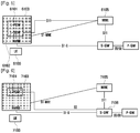
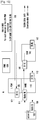
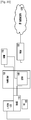
- FIG. 1 is a schematic diagram illustrating an architecture of a wireless communication system according to an embodiment of the present invention.
- the wireless communication system includes a UE 100, a femto base station 103 including a Local PDN GateWay (L-PGW) 101 and a Local Serving GateWay (L-SGW) 102, a macro base station (or eNB) 108, a femto base station gateway (or HeNB GW) 104, an MME 105, a macro serving gateway (S-GW) 106, and a PDN gateway (P-GW) 107.
- the S-GW 106 and P-GW 107 are included in a core network.
- the UE 100 can access the core network via the eNB 108 or the HeNB 103.
- the L-PGW 101 is a local PDN gateway implemented in the HeNB 103
- the L-SGW 102 is the local serving gateway implemented in the HeNB 103.
- the HeNB 103 is connected to the core network through the MME 105 to provide the UE 101 with a mobile communication service.
- the HeNB 103 can be referred to as Closed Subscriber Group (CSG) cell, which permits access of a specific group of UEs.
- the CSG cell can be a home cell installed in a small area, e.g., within a home, or a business/local network cell for covering relatively large area.
- the HeNB 103 permits the access of the registered UEs for the mobile communication service and broadcasts a CSG-ID in a System Information Block (SIB) message.
- SIB System Information Block
- the HeNB GW 104 connects the HeNB 103 to the MME 105.
- the MME 105 manages the UEs in idle mode and selecting the S-GW 106 and P-GW 107. Also, the MME 105 is responsible for functions related to the roaming and authentication. Further, the MME 105 processes bearer signaling generated by the UE 100.
- the S-GW 106 acts as a mobility anchor in a handover of the UE 100 between base stations (including eNB 108 and HeNB 103) or between 3GPP radio access networks.
- the P-GW 107 allocates an IP address to the UE 100, performs packet data-related functions of the core network, and acts as an anchor for the mobility between 3GPP radio access network and non-3GPP radio access network.
- the P-GW 107 is also responsible for the bearer bandwidth determination and forwarding and routing functions.
- the eNB 108 is a base station responsible for the macrocell.
- the eNB 108 establishes a radio channel with the UE 100 and manages radio resources. For example, the eNB 108 broadcasts system information including the control information required in the macro cell and allocates radio resources for communications with the UE 100.
- the eNB 108 also can determine handover based on a measurement report fed back by the UE 100 and send a handover command to the UE 100.
- the eNB 108 includes a control protocol such as Radio Resource Protocol (RRP) for radio resource management.
- RRP Radio Resource Protocol
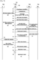
- FIGs. 1 and 2 are diagrams illustrating network architectures of wireless communication systems according to embodiments of the present invention
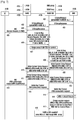
- FIG. 7 is a signaling diagram illustrating operations of network entities for supporting local IP access in systems as illustrated in FIGs. 1 and 2 .
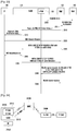
- the HeNB 103 or the HeNB GW 104 is allocated an IP address according to a Dynamic Host Configuration Protocol (DHCP) or static configuration and establishes a connection with the MME 105. More specifically, the HeNB GW 104 transmits an S1 SETUP REQUEST message including its own Identification (ID) to the MME 105 in step 201 and receives an S1 SETUP RESPONSE message from the MME 105 in step 202. In step 203, the HeNB 103 transmits an S1 SETUP REQUEST message including its ID to the HeNB GW 104 and receives an S1 SETUP RESPONSE message from the HeNB GW 104 in step 204.
- DHCP Dynamic Host Configuration Protocol
- the UE 100 transmits a SERVICE REQUEST message toward the MME 105 via the HeNB 103 in step 205.
- the HeNB 103 transmits an INITIAL UE message including the SERVICE REQUEST message of the UE to the HeNB GW 104 in step 206.
- the INITIAL UE message may include local gateway information (Local GW-info) including the information for exchanging a control message such as IPv4 and/or IPv6 addresses and ports of the L-PGW 101 and L-SGW 103.
- the HeNB GW 104 stores the S-TMSI for use between the HeNB GW 104 and the MME 105 and the local GW-info that are carried in the INITIAL UE message and forwards the INITIAL UE message to the MME 105.
- the MME 105 transmits an INITIAL CONTEXT SETUP REQUEST message including the information on the establishment of a radio bearer for the UE to the HeNB GW 104.
- the HeNB GW 104 forwards the INITIAL CONTEXT SETUP REQUEST message to the HeNB 103 in step 209.
- the HeNB 103 stores the information related to the establishment of radio bearer for the UE 100 and transmits an INITIAL CONTEXT SETUP RESPONSE message toward the MME 105 via the HeNB GW 104.
- the HeNB GW 104 forwards the INITIAL CONTEXT SETUP RESPONSE message to the MME 105 in step 211.
- the UE 100 After the radio bearer establishment information is transmitted to the HeNB 103, the UE 100 transmits a PDN CONNECTIVITY REQUEST message for local IP access to the HeNB 103 in step 212.
- the HeNB 103 forwards the PDN CONNECTIVITY REQUEST message to the HeNB GW 104 in step 213, and the HeNB GW 104 forwards the PDN CONNECTIVITY REQUEST message to the MME 105 in step 214.
- step 215 the MME 105 checks whether the request is for local IP access. If it is determined that the request is for local IP access, in step 216, the MME 105 transmits a CREATE SESSION REQUEST message directly to the L-SGW 102 using the local gateway information acquired from the INITIAL UE message.
- the L-SGW 102 Upon receipt of the CREATE SESSION REQUEST message, the L-SGW 102 establishes the requested radio bearer with the L-PGW 101, i.e. the bearer directly connecting the L-SGW 102 and the L-PGW 101, in step 217. In step 218, the L-SGW 102 transmits a CREATE SESSION RESPONSE message to the MME 105 for reporting the bearer establishment result.
- the MME 105 checks the bearer established between the L-SGW 102 and the L-PGW 101 by referencing the CREATE SESSION RESPONSE message and transmits a BEARER SETUP REQUEST message for setting up the radio bearer and a PDN CONNECTIVITY ACCEPT message for accepting the PDN connection toward the UE via the HeNB 103.
- the HeNB 103 Upon receipt of the BEARER SETUP REQUEST and PDN CONNECTIVITY ACCEPT message, the HeNB 103 establishes the radio bearer with the UE 100 in step 220 and forward the PDN CONNECITIVITY ACCEPT message to the UE 100.
- the HeNB 103 After the establishment of the radio bearer, the HeNB 103 transmits a BEARER SETUP RESPONSE message to the MME 105 in step 221, and the UE 100 transmits a PDN CONNECTIVITY COMPLETE message to the HeNB 103 in step 222. The HeNB 103 forwards the PDN CONNECTIVITY COMPLETE message to the MME 105 in step 223.
- the MME 105 Upon receipt of the PDN CONNECTIVITY COMPLETE message, the MME 105 determines whether the update of the information related to the radio bearer is required in the L-SGW 102 or L-PGW 101. If it is determine that radio bearer information update is required in the L-SGW 102 or L-PGW 101, the MME 105 transmits a MODIFY BEARER REQUEST message including the update bearer information to the L-SGW 102 in the HeNB 103 in step 224. In response to the MODIFY BEARER REQUEST message, the L-SGW 102 transmits a MODIFY BEARER RESPONSE message to the MME 105 in step 225. If the MODIFY BEARER REQUEST message is received, the MME ends the local PDN connection establishment procedure.
- the local GW-info transmitted in the INITIAL UE message in step 203 can be carried by the INITIAL CONTEXT SETUP RESPONSE message in step 210.
- the method of FIG. 7 can also be applied to a system as illustrated in FIG. 2 in which only the L-PGW 1010 is included in the HeNB 1030 with the involvement of the S-GW 1060.
- the messages transmitted from the MME 105 to the L-SGW 102 and the L-PGW 101 in the embodiment illustrated in FIG. 1 are instead transmitted from the MME 1050 to the L-PGW 1010 via the SGW 1060.
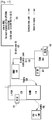
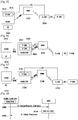
- FIGs. 3 and 4 are diagrams illustrating network architectures of wireless communication systems according to embodiments of the present invention
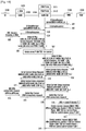
- FIGs. 8 to 11 are signaling diagrams illustrating operations of network entities for supporting local IP access in systems as illustrated in FIGs. 3 and 4 .
- the HeNB 4103 or the HeNB GW 4104 is allocated an IP address according to a DHCP or static configuration and establishes a connection with the MME 4105. More specifically, the HeNB GW 4104 transmits an S1 SETUP REQUEST message including its ID to the MME 4105 in step 401. In step 402, the MME 4105 transmits an S1 SETUP RESPONSE message to the HeNB GW 4104.
- the HeNB 4103 also transmits an S1 SETUP REQUEST message including its ID to the HeNB GW 4104.
- the HeNB GW 4104 Upon receipt of the S1 SETUP REQUEST message, the HeNB GW 4104 transmits an S1 SETUP RESPONSE message to the HeNB 4103 in step 404, thereby establishing a connection between the HeNB 4103 and the HeNB GW 4104.
- the UE After the establishment of the connections between the HeNB 4103 and the HeNB GW 4104 and between the HeNB GW 4104 and the MME 4105, the UE transmits a SERVICE REQUEST message to the HeNB 4103 in step 405.
- the HeNB 4103 transmits an INITIAL UE message indicating the receipt of the SERVICE REQUEST message from the UE to the HeNB GW 4104.
- the INITIAL UE message carries the local gateway information (Local GW-info) including the information required for the control message exchange such as IPv4 and/or IPv6 addresses and ports of the L-PGW 4101 and the L-SGW 4102.
- the HeNB GW 4104 stores the S-TMSI as the UE ID for use between the MME 4105 and the HeNB 4103 and the Local GW-info that is carried by the INITIAL UE message and assigns an SGW proxy for processing the information transmitted from the MME 4105 to the L-SGW 4102 in step 407.
- the HeNB GW 4104 forwards the INITIAL UE message to the MME 405.
- the MME 4105 Upon receipt of the INITIAL UE message, the MME 4105 transmits an INITIAL CONTEXT SETUP REQUEST message including the information related to the establishment of a radio bearer for the UE to the HeNB GW 4104 in step 409. The HeNB GW 4104 forwards the INITIAL CONTEXT SETUP REQUEST message to the HeNB 4103 in step 410.
- the HeNB 4103 Upon receipt of the INITIAL CONTEXT SETUP REQUEST message, the HeNB 4103 stores the information related to the establishment of the radio bearer for the UE 4100 and transmits an INITIAL CONTEXT SETUP RESPONSE message to the HeNB GW 4104 in step 411. The HeNB GW 4104 forwards the INITIAL CONTEXT SETUP RESPONSE to the MME 4105 in step 412.
- step 413 after the HeNB 4103 has acquired the information related to the establishment of the radio bearer for the UE, the UE 4100 transmits a PDN CONNECTIVITY REQUEST message to the HeNB 4103.
- the PDN CONNECTIVITY REQUEST message is transmitted to request the PDN connection establishment for local IP access.
- the HeNB 4103 forwards the PDN CONNECTIVITY REQUEST message to the MME 4105 via the HeNB GW 4104 in steps 414 and 415.
- the MME 4105 Upon receipt of the PDN CONNECTIVITY REQUEST message, the MME 4105 determines if the PDN CONNECTIVITY REQUEST message is transmitted for the purpose of the local IP access in step 416.
- the MME 4105 transmits a CREATE SESSION REQUEST message including the local gateway information, which is acquired from the INITIAL UE message in step 408, to the HeNB GW 4104 in step 417.
- the CREATE SESSION REQUEST message can include a same IMSI as the UE ID for use between the serving gateway and the MME 4104, a same S-TMSI as the UE ID for use between the HeNB and MME 4105, and L-PGW information acquired from the INITIAL UE message in step 408.
- the CREATE SESSION REQUEST message also can include the information on the L-SGW 4102 acquired from the INITIAL UE message in step 408.
- the information on the L-SGW 4102 can include the information on the SGW proxy 4110 that is assigned by the HeNB GW 4104, such that the CREATE SESSION REQUEST message is transferred to the SGW proxy 4110 in the HeNB GW 4104.
- the HeNB GW 4104 Upon receipt of the CREATE SESSION REQUEST message, the HeNB GW 4104 saves the IMSI and S-TMSI extracted from the CREATE SESSION REQUEST message and assigns an MME proxy 4109 in step 418. Thereafter, the HeNB GW 4104 searches for the L-SGW to receive the CREATE SESSION REQUEST message with reference to the S-TMSI and Local GW-info acquired from the INITIAL UE message in step 406.
- the HeNB GW 4104 forwards the CREATE SESSION REQUEST message to the found L-SGW 4102 in the HeNB 4103 in step 419.
- the HeNB GW 4104 assigns the MME proxy 4109, such that the control messages destined to the MME 4105 are relayed via the MME proxy 4109.
- the CREATE SESSION REQUEST message includes the information on the address and port of the MME proxy 4109 and Sender Full-Tunnel Endpoint Identifier (F-TEID) for Control Plane which is equal to Proxy MME TEID assigned by the HeNB GW 4104.
- F-TEID Sender Full-Tunnel Endpoint Identifier
- the L-SGW 4102 Upon receipt of the CREATE SESSION REQUEST message, the L-SGW 4102 requests the L-PGW 4101 to create a session between the L-SGW 4102 and the L-PGW 4101 in step 420. In step 421, the L-SGW 4102 transmits a CREATE SESSION RESPONSE message to the MME proxy 4109 in the HeNB GW 4104. The HeNB GW 4104 resets the Sender F-TEID included in the CREATE SESSION RESPONSE message to the ID of the SGW proxy 4110 and forwards the CREATE SESSION RESPONSE message to the MME 4105 in step 422.
- the MME 4105 transmits a BEARER SETUP REQUEST message for requesting radio bearer establishment from the HeNB GW 4104 along with the PDN CONNECTIVITY ACCEPT message indicating that the PDN connection is accepted.
- the HeNB GW 4104 Upon receipt of the BEARER SETUP REQUEST and PDN CONNECTIVITY ACCEPT messages, the HeNB GW 4104 forwards the BEARER SETUP REQUEST and PDN CONNECTIVITY ACCEPT messages to the HeNB 4103 in step 424.
- the HeNB 4103 establishes a radio bearer (RRC connection) with the UE 4100.
- RRC connection radio bearer
- the HeNB 4103 After the establishment of the RRC connection between the UE 4100 and the HeNB 4103, the HeNB 4103 transmits a BEARER SETUP RESPONSE message indicating the RRC connection establishment to the HeNB GW 4104 in step 426.
- the HeNB GW 4104 forwards the BEARER SETUP RESPONSE message to the MME 4105 in step 427.
- the UE 4100 After the BEARER SETUP RESPONSE message is transmitted from the HeNB 4103 to the MME 4105, the UE 4100 transmits a PDN CONNECTIVITY COMPLETE message indicating the completion of the PDN connection establishment for local IP access to the HeNB 4103 in step 428.
- the HeNB 4103 forwards the PDN CONNECTIVITY COMPLETE message to the HeNB GW 4104 in step 429, and the HeNB GW 4104 forwards the PDN CONNECTIVITY COMPLETE message to the MME 4105 in step 430.
- the MME 4105 transmits a MODIFY BEARER REQUEST message to the L-SGW 4102 via the SGW proxy 4110 in steps 431 and 432.
- the L-SGW 4102 updates the radio bearer-related information with the L-PGW 4101 in the HeNB 4103.
- the L-SGW 4102 transmits a MODIFY BEARER RESPONSE message to the MME 4105 via the MME proxy 4109, thereby completing the local PDN connection establishment.
- the local GW-info is carried by the S1 SETUP REQUEST message in step 403 and the INITIAL CONTEXT SETUP REQUEST message in step 410.
- steps 431 to 435 are then not performed.
- the procedure described with reference to FIGs. 3 , 8 , and 9 can also be applied in network architecture as illustrated in FIG. 4 , which includes an L-PGW 5105 implemented in an HeNB 5103 and uses a macro SGW 5106.
- the data path can be established according to a procedure as illustrated in FIGs. 10 and 11 .
- the data path establishment procedure illustrated in FIGs. 10 and 11 for a network architecture as illustrated in FIG. 4 differs from that illustrated in FIGs. 8 and 9 for a network architecture as illustrated in FIG. 3 in that a PGW proxy 5112 is assigned in the HeNB GW 5104 in step 507 of FIG. 10 , unlike where the SGW proxy 4110 is assigned in the HeNB GW 4104 in step 407 of FIG. 8 .
- the INITIAL UE message transmitted in step 508 of FIG. 10 carries only the access information of the PGW proxy 5112, unlike the INITIAL UE message transmitted in step 408.
- the CREATE SESSION REQUEST message is transmitted from the MME 5105 to the PGW proxy 5112 via the macro SGW 5106 in step 517 of FIG.
- the CREATE SESSION REQUEST message transmitted by the macro SGW 5106 in step 518 includes the same IMSI and S-TMSI as the CREATE SESSION REQUEST message transmitted by the MME 5105 in step 517.
- an SGW proxy 5111 is assigned in step 519 of FIG. 11 , and the CREATE SESSION REQUEST message transmitted from the HeNB GW 5104 to the HeNB 5103 in step 520 includes the access information for the SGW proxy 5111.
- the CREATE SESSION RESPONSE message transmitted from the HeNB 5103 to the SGW 5106 via the HeNB GW 5104 in step 522 includes the Sender F-TEID reset for the PGW proxy 5112.
- the CREATE SESSION RESPONSE message forwarded from the SGW 5106 to the MME 5105 in step 523 includes the Sender F-TEID reset for the macro SGW 5106.
- the MODIFY BEARER REQUEST message is transmitted from the HeNB GW 5104 to the HeNB 5103, when update is required, for carrying the modified bearer information in step 534 toward L-GW via the SGW proxy 5111.
- Steps 509 to 516 of FIG. 10 are identical with steps 409 to 416 of FIG. 8
- steps 524 to 531 of FIG. 11 are identical with steps 423 to 430 of FIG. 9 . Accordingly, a repetitive description will not be presented.
- the Local GW-info can be carried by the S1 SETUP REQUEST message in step 503 and the INITIAL CONTEXT SETUP RESPONSE message in step 512.
- steps 523 to 536 are not performed.
- FIGs. 5 and 6 are diagrams illustrating network architectures of wireless communication systems according to embodiments of the present invention
- FIGs. 12 and 13 are signaling diagrams illustrating operations of network entities for supporting local IP access in the systems illustrated in FIGs. 12 and 13 .
- the HeNB 6103 is allocated an IP address according to the DHCP or static configuration and establishes a connection with the MME 6105. More specifically, the HeNB 6103 transmits an S1 SETUP REQUEST message to the MME 6105 in step 601.
- the S1 SETUP REQUEST message can include the collocated local SGW or local PGW information as seen in Fig 28 .
- the MME 6105 transmits an S1 SETUP RESPONSE message to the HeNB 6103, thereby establishing a connection between the HeNB 6103 and the MME 6105.
- the UE 6100 After the connection establishment between the HeNB 6103 and the MME 6105, the UE 6100 transmits a SERVICE REQUEST message to the HeNB 6103 in step 603. In step 604, the HeNB 6103 transmits an INITIAL CONTEXT SETUP REQUEST message to the MME 6105.
- the INITIAL CONTEXT SETUP REQUEST message includes Local GW-info including the IPv4 and/or IPv6 addresses and ports of the L-PGW 6101 and the L-SGW 6102 and the SERVICE REQUEST message transmitted by the UE 6100.
- the MME 6105 Upon receipt of the INITIAL UE message, the MME 6105 saves the UE information including the S-TMSI as the UE ID for use between the HeNB 6103 and the MME 6105 and the Local GW-info that is carried by the INITIAL UE message and transmits an INITIAL CONTEXT SETUP REQUEST message to the HeNB 6103 in step 605.
- the INITIAL CONTEXT SETUP REQUEST message includes the information required for establishing radio bearer between the UE 6100 and the HeNB 6103.
- the HeNB 6103 transmits an INITIAL CONTEXT SETUP COMPLETE message to the MME 6105 in step 606.
- the UE 6100 transmits a PDN CONNECTIVITY REQUEST message to the HeNB 6103 to establish a PDN connection for local IP access in step 607.
- the HeNB 6103 forwards the PDN CONNECTIVITY REQUEST message to the MME 6105 in step 608.
- the MME 6105 Upon receive the PDN CONNECTIVITY REQUEST message, the MME 6105 identifies that the PDN CONNECTIVITY REQUEST message is a PDN connection request for local IP access. When the PDN CONNECTIVITY REQUEST message is the PDN connection request for the local IP access, the MME 6105 transmits a CREATE SESSION REQUEST message including the IMSI as the UE ID for use in the original CREATE SESSION REQUEST message transmitted to the L-SGW 6102 and the S-TMSI as the UE ID for use between the HeNB 6103 and the MME 6105 to the HeNB 6103 in step 609. The MME 6105 refers to the local gateway information acquired from the INITIAL UE message in order to transfer the CREATE SESSION REQUEST message directly to the local SGW 6102.
- the L-SGW 6102 Upon receipt of the CREATE SESSION REQUEST message, the L-SGW 6102 establishes a bearer indicated by the CREATE SESSION REQUEST message with the L-PGW 6101 in step 610. In step 611, the L-SGW 6102 transmits a CREATE SESSION RESPONSE message to the MME 6105 for informing of the bearer establishment result.
- the MME 6105 Upon receipt of the CREATE SESSION RESPONSE message, the MME 6105 identifies the bearer establishment and transmits a BEARER SETUP REQUEST message for establishing a radio bearer and a PDN CONNECTIVITY ACCEPT message informing acceptance of the PDN connection establishment to the HeNB 6103 in step 612.
- the HeNB 6103 If the BEARER SETUP REQUEST and PDN CONNECTIVITY ACCEPT messages are received, the HeNB 6103 establishes a radio bearer (RRC connection) with the UE 6100 in step 613. In step 614, the HeNB 6103 transmits a BEARER SETUP RESPONSE message including the RRC connection result to the MME 6105.
- RRC connection radio bearer
- the UE 6100 After the RRC connection establishment, the UE 6100 transmits a PDN CONNECTIVITY COMPLETE message to the HeNB 6103 in step 615.
- the HeNB 6103 forwards the PDN CONNECTIVITY COMPLETE message to the MME 6105 in step 616.
- the MME 6105 transmits a MODIFY BEARER REQUEST message for updating the radio bearer information to the L-SGW 6102.
- the L-SGW 6102 requests the L-PGW 6101 to update the radio bearer information and receives a response.
- the L-SGW 6102 transmits a MODIFY BEARER RESPONSE message to the MME 6105 in response to the MODIFY BEARER REQUEST message, thereby completing the local connection establishment procedure.
- the Local GW-info transmitted in the INITIAL UE message in step 604 can be carried by the S1 SETUP REQUEST message in step 601 and the initial context setup complete message in step 606.
- the CREATE SESSION REQUEST message transmitted from the MME 6105 to the HeNB 6103 in step 609 can include the S-TMSI without the IMSI.
- the network can be configured as illustrated in FIG. 6 , wherein the HeNB 7103 includes only the L-PGW 7101 and the macro serving gateway 7106 performs the function of the L-SGW 6102 of FIG. 5 .
- the MME 7105 transmits the CREATE SESSION REQUEST message to the SGW 7106 in step 709, and the SGW 7106 forwards the CREATE SESSION REQUEST message to the L-PGW 7101 of the HeNB 7103 in step 710.
- Both CREATE SESSION REQUEST messages include the S-TMSI.
- the L-PGW 7101 transmits the CREATE SESSION RESPONSE message informing of the bearer establishment result to the macro SGW 7106 in step 711, and the macro SGW 7106 forwards the CREATE SESSION RESPONSE message to the MME 7105 in step 712.
- Steps 701 to 709 of FIG. 13 are identical with steps 601 to 609 of FIG. 12
- steps 713 to 719 are identical with steps 612 to 618 of FIG. 12 . Accordingly, a repetitive description will not be presented.
- the CREATE SESSION REQUEST message transmitted from the SGW 7101 to the HeNB 7103 may the S-TMSI without the IMSI.
- a UE connected to an HeNB can directly access a local IP Access service without passing through the carrier's network. Because the HeNB is responsible for the functions of the local gateway (local PGW with or without L-SGW), the UE connected to a HeNB can directly access the PDN without involvement of the core network, resulting in improvement of data transmission efficiency. Because the HeNB is responsible for gateway relay function, it is possible to use the security function as a local gateway and thus, improve the communication security between the HeNB and the MME of the core network.
- FIG. 14 is a diagram illustrating a network architecture of a wireless communication system including an HeNB according to an embodiment of the present invention.
- the wireless communication system includes a UE 100, a femto base station (or HeNB) 110 having extended functionality with an L-PGW 120, an MME 130, an SGW 140, a PGW 150, a macro base station (or eNB) 160, and an IP network 170.
- a femto base station or HeNB 110 having extended functionality with an L-PGW 120, an MME 130, an SGW 140, a PGW 150, a macro base station (or eNB) 160, and an IP network 170.
- FIG. 15 is a diagram illustrating a data path established for a UE in an active mode to access an IP network in a system as illustrated in FIG. 14 .
- the UpLink (UL) data transmitted from the UE 100 to the IP network 170 is delivered over the radio UL 111 between the UE and the HeNB 110, over the S1 UL 141 between the HeNB 110 and the SGW 140, over the S5 UL between the SGW 140 and the L-PGW 120, and an IP network interface between the L-PGW 120 and the IP network 170.
- UL UpLink
- the DownLink (DL) data transmitted from the IP network 170 to the UE 100 is delivered over the reverse path. That is, the DL data transmitted from the IP network 170 to the UE 100 is delivered over the S5 DL 142 between the L-PGW 120 and the SGW 140, over the S1 DL 112 between the SGW 140 and the HeNB 110, and over the radio DL 101 between the HeNB 110 and the UE 100.
- the MME 130 In order to process the UL and DL data, the MME 130 has the bearer information 191 about the S5 UL 121 of the L-PGW and the S1 UL 141 and the S5 DL 142 of the SGW 140 for the UE 100.
- the bearer information 191 lists only the S5 DL of the data plane in FIG. 15 , it can also include other information mentioned above.
- FIG. 16 is a diagram illustrating a control path established for a UE in an active mode to access an IP network in a system as illustrated in FIG. 14 .
- the UE 100 in an active mode transmits a control message to the L-PGW 120 through an RRC connection 10 established between the UE 100 and the HeNB 110.
- the control message transmitted the UE 100 to the L-PGW 120 is delivered over the series of the RRC link between the UE 100 and the HeNB 110, the S1-AP interface 11 between the HeNB 110 and the MME 130, the S11 GTP interface 12 between the MME 130 and the SGW 140, and the S5 GTP interface 13 between the SGW 140 and the L-PGW 120.
- the control message transmitted from the L-PGW 120 to the UE 100 is delivered over the reverse path.
- FIG. 17 is a diagram illustrating data and control paths established for a UE in an idle mode to access an IP network in a system as illustrated in FIG. 14 , according to an embodiment of the present invention.
- the HeNB 110 erases the UE information and bearer information (about S1 DL 101 and radio UL 111) for data communication with the UE 100. However, the HeNB 110 retains the information on the S1 UL 141 and S5 DL 142 in the SGW 140, the information on the S5 UL 121 in L-PGW 120, and the bearer information 191 in the MME 130.
- the L-PGW 120 transmits the DL data 192 to the SGW 140 over the S5 DL 142.
- the SGW 140 transmits a DL data notification message 193 to the MME 130 while buffering the DL data 192.
- the MME 130 transmits a paging trigger message 194 to the HeNB 110.
- the HeNB 110 transmits a paging message 195 to UE 100, instructing the UE 100 to transition from the idle mode to the active mode.
- FIG. 18 is a diagram illustrating a data path established for a UE in an active mode to access an IP network in a system according to an embodiment of the present invention.
- the UL data transmitted from the UE 100 to the IP network 170 is delivered over a series of the radio UL 111 between the UE 100 and the HeNB 110, the S5 UL 121 between the HeNB 110 and the L-PGW 120, and an IP link between the L-PGW 120 and the IP network 170. Accordingly, the UL data can be delivered through the shortest data path.
- the DL data at the L-PGW 120 is transmitted over the S1 DL between the L-PGW 120 and the HeNB 110 and the radio DL between the HeNB 110 and the UE 100, resulting in delivery over the shortest data path.
- the MME 130 stores bearer information 196 including the information on the S1 DL for the UE 100 operating in the active mode in addition to information stored in the MME of FIG. 18 .
- the L-GW stores both S5 DL 142 for the idle UE and S1 DL 112 for the active UE, and switches which one is actually used when the UE state change from the idle state to active state and vice versa.
- the MME should give the indication to the L-GW about the change of the UE state.
- the bearer information 196 of the MME 130 includes the information on the S5 DL and S1 DL for the data plane of the UE 100 in FIG. 18 , the present invention is not limited thereto. Additionally, a procedure for configuring a data path of FIG. 18 will be described in more detail below with reference to FIG. 22 .
- FIG. 19 is a diagram illustrating a control path established for a UE in an active mode to access an IP network in a system according to an embodiment of the present invention.
- the control message transmitted from the UE 100 to the MME 130 is delivered over a series of the RRC connection 10 between the UE 100 and the HeNB 110 and the S1-AP interface 11 between the HeNB 110 and the MME 130.
- the control message transmitted from the MME 130 to the L-PGW 120 is delivered over a series of the S1-AP interface between the MME 130 and HeNB 110 and an internal path between the HeNB 110 and the L-PGW 120 using a GTP message container.
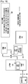
- FIG. 20 is a diagram illustrating a network architecture of a wireless communication system including an HeNB according to an embodiment of the present invention.
- the wireless communication system includes a UE 100, an HeNB 110 having extended functionality with an L-PGW 120, an HeNB GW 130, a macro (or serving) SGW 140, an MME 150, a macro (or PDN) PGW 160, and an IP network 170.
- data path reconfiguration is performed with the paging process as described with reference to FIG. 17 . Additionally, the data path reconfiguration procedure will be described in more detail below with reference to FIG. 22 . Further, the data path reconfiguration according to the operation mode transition of the UE from the idle mode to the active mode will be described in more detail below with reference to FIG. 23 .
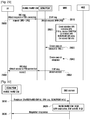
- FIG. 21 is a signaling diagram illustrating operations of network entities for establishing a data path for a UE operating in an active mode in a system as illustrated in FIG. 20 , according to an embodiment of the present invention.
- the UE 100 first establishes a Radio Resource Control (RRC) connection with the HeNB 110 and transmits a SERVICE REQUEST message to the HeNB 110 to establish a PDN connection for using the local IP access service in step 2100.
- RRC Radio Resource Control
- the HeNB 110 transmits an INITIAL UE message including the SERVICE REQUEST message to the MME 130.
- the INITIAL UE message also includes the local GW information (Local GW-info) including the information on the L-PGW 120 of the HeNB 110 and an optimal control message enable indicator (optimal_ctrl_enable_indicator).
- the Local GW-info includes the access information such as the address for the L-PGW to receive control messages (IP address or Fully Qualified Domain Name (FQDN)) and GPRS Tunneling Protocol Tunnel End-point ID (TEID).
- the optimal_ctrl_enable_indicator indicates that the GTP control message transmitted from the MME 130 to the L-PGW 120 in the GTP message container over the control connection between the HeNB 110 and the MME (see FIG. 19 ) can be processed.
- the MME 130 activates all of the bearers used by the UE 100 in step 2110. Once the bearers are activated, the UE 100 transmits a PDN CONNECTIVITY REQUEST message to the MME 130 in step 2115. At this time, the Access Point Name (APN) of the PDN CONNECTIVITY REQUEST message, which indicates the target access network, is set to "Local IP Access”.
- APN Access Point Name
- the MME 130 Upon receipt of the PDN CONNECTIVITY REQUEST message, the MME 130 checks the APN to determine whether the target network is a Local IP network request and the Local GW-Info to determine whether the local IP access functions is supportable. For the decision, the MME checks the L-GW information in the initial UE message. (Other alternatives are using DNS or S1 Setup procedure as seen in Fig 28 , 29 , 30 , 31 ).. The MME 130 selects a PGW and/or SGW based on the checking result.
- the MME 130 acquires the IP address of the network using a Domain Name Server (DNS). If it is determined to use the L-PGW 120 and a LIPA direct path for connecting the data path of the UE in active mode to the L-PGW directly, the MME 130 transmits a CREATE SESSION REQUEST message containing the S-TMSI with IMSI to the SGW 140 in step 2120.
- DNS Domain Name Server
- the SGW 140 recognizes the S-TMSI included in the CREATE SESSION REQUEST message as the indicator to use of the L-PGW. If the CREATE SESSION REQUEST message includes the S-TMSI, the SGW 140 forwards the CREATE SESSION REQUEST message to the L-PGW 120 in step 2125. At this time, the SGW 140 resets the UE ID by substituting the S-TMSI for the IMSI.
- the SGW 140 recognizes the LIPA-direct-tunnel-on-indicator included in the CREATE SESSION REQUEST message transmitted by the MME 130 as an indicator indicating that there is no need for the SGW 140 to allocate resource to the UE 100 and thus does not allocates any resource for the data path.
- the S5 DL for use in idle mode or the resource for the data path required when the UE transitions from the active mode to the idle mode in step 2225 of FIG. 22 can be allocated.
- the SGW 140 After processing the received CREATE SESSION REQUEST message, the SGW 140 forwards the CREATE SESSION REQUEST message with the S-TMSI as the UE ID to the L-PGW 120 in step 2125.
- the L-PGW 120 Upon receipt of the CREATE SESSION REQUEST message, the L-PGW 120 allocates the required resource and transmits a CREATE SESSION RESPONSE message to the SGW 140 in step 2130.
- the SGW 140 forwards the CREATE SESSION RESPONSE message to the MME 130 in step 2135.
- the SGW 140 sets the resource information (S1 UL 141 and S5 DL 142) to dummy data or turns on the LIPA-direct-tunnel-flag in the CREATE SESSION RESPONSE message.
- the MME 130 Upon receipt of the CREATE SESSION RESPONSE message, the MME 130 transmits a BEARER SETUP REQUEST message to the HeNB 110 in step 2140.
- the BEARER SETUP REQUEST message includes the address and TEID of the L-PGW 120 that are acquired from the CREATE SESSION RESPONSE message as the destination address for transmitting the data received through the radio UL 111 at the HeNB 110.
- the MME 130 determines to use the GTP control message as the container for carrying the control message between the HeNB 110 and the MME 130, the MME inserts the optimal_cntrl_enable_indicator in the BEARER SETUP REQUEST message to indicate the use of the GTP control message.
- the BEARER SETUP REQUEST message can be transmitted along with a PDN connection accept message.
- the HeNB 110 Upon receipt of the BEARER SETUP REQUEST and PDN CONNECTIVITY ACCEPT messages, the HeNB 110 sets up the radio bearer with the UE 100 in step 2145 and transmits a BEARER SETUP RESPONSE message containing the information on the S1 DL 112 allocated for receiving the DL data to the MME 130 in step 2150.
- the MME 130 Upon receipt of the BEARER SETUP RESPONSE, the MME 130 saves the information on the S1 DL 112 for the HeNB 110 to receive the downlink data, and the UE transmits a PDN CONNECTIVITY COMPLETE message to the MME 130 in step 2155.
- the MME 130 transmits a MODIFY BEARER REQUEST message including the information on the S1 DL 112 configured by the HeNB 110 to the control message reception address of the L-PGW 120, which is acquired from the CREATE SESSION RESPONSE message through steps 2130 and 2135, such that the data received from the L-PGW 120 is transmitted over the S1 DL in step 2160.
- the MODIFY BEARER REQUEST message can be transmitted in three ways. The first way is using the container over the control connection between the HeNB 110 and the MME 130.
- the second way is using L-GW control address obtained using UE initial message, S1 setup message or DNS query, i.e. sending the MODIFY BEARER REQUEST directly to L-GW control address.
- the third way is via SGW, i.e. the MME sends the MODIFY BEARER REQUEST to S-GW with the LIPA-direct-tunnel-flag and then the S-GW just passes the received MODIFY BEARER REQUEST to L-GW without processing.
- the L-PGW 120 saves the information on the S1 DL allocated by the HeNB 110 and establishes an LIPA direct tunnel as described with reference to FIG. 18 and in step 2165, forwards the MODIFY BEARER RESPONSE message to the control message reception address of the MME 130 that is acquired from the CREATE SESSION REQUEST message through steps 2120 and 2125.
- Sending the MODIFY BEARER RESPOSNE also can be done in the three ways -using the GTP-C container over S1-MME interface, using L-GW control address and using S-GW passing.
- FIG. 22 is a signaling diagram illustrating operations of network entities when reconfiguring a data path for a UE to receive a paging message, after transition to an idle mode, according to an embodiment of the present invention.
- the HeNB 110 transmits a UE CONTEXT RELEASE REQUEST message to the MME 130 for releasing the context of the UE in step 2200.
- the MME 130 transmits a MODIFY BEARER REQUEST message to the SGW 140 for switching the downlink data path from the S1 DL 112 between the L-PGW 120 and the HeNB 110 (see FIG. 18 ) to the S5 DL 142 between L-PGW and the SGW 140 (see FIG. 17 ) in step 2210.
- the SGW 140 forwards the MODIFY BEARER REQUEST message to the L-PGW 120 in step 2215.
- the MODIFY BERARER REQUEST can be delivered within a container in S1AP : UE Context Release Command from in Figure 22 .
- the MODIFY BEARER REQUEST message transmitted by the MME 130 contains the S-TMSI for indicating that the data path of the bearers used for a Local IP Access (LIPA) direct tunnel is switched.
- the MODIFY BEARER REQUEST message also includes the most recent bearer-related information, such as deactivation, activation, and modification of the bearers, that has been executed without notification to the SGW 140 for control message transmission efficiency so as to update the information on the bearers in the SGW 140.
- the SGW 140 checks the S-TMSI included in the MODIFY BEARER REQUEST message to recognize the path switch of the LIPA direct tunnel and allocates the resource for receiving and buffering the downlink data destined to the UE 100 using the information on the modified bearers extracted from the MODIFY BEARER REQUEST message. Additionally, the SGW 140 updates its bearer information. If the MME 130 has not allocated resources for the uplink and downlink data when it has received the CREATE SESSION REQUEST in step 2120 of FIG.
- a resource such as a TEID at a time point when the MODIFY BEARER REQUEST message is received can be allocated in the state where the UE transitions to the idle mode.
- the MODIFY BEARER REQUEST message transmitted by the SGW 140 includes the information on the modified bearers as the update result.
- the L-PGW 120 Upon receipt of the MODIFY BEARER REQUEST message, the L-PGW 120 switches the downlink data path from the S1 DL 112 established between the L-PGW 120 and the HeNB 110 to the S5 DL 142 between the L-PGW 120 and the SGW 140 based on the bearer information of the SGW 140 extracted from the MODIFY BEARER REQUEST message in step 2220. In step 2225, the L-PGW 120 transmits a MODIFY BEARER RESPONSE message including the data path switching result to the SGW 140. The SGW 140 forwards the MODIFY BEARER REQUEST message to the MME 130 in step 2230.
- the MME 130 saves the UE context indicating that the UE camped on the HeNB 110 uses the LIPA-direct-tunnel for the bearers at the HeNB in step 2235.
- the MME 130 transmits a UE CONTEXT RELEASE COMMAND message to the HeNB 110 for releasing the resources and information and the radio bearers allocated to the UE 100.
- the HeNB 110 Upon receipt of the UE CONTEXT RELEASE COMMAND message, the HeNB 110 transmits an RRC CONNECTION RELEASE message to the UE 100 in step 2245 and releases the resource allocated to the UE 100.
- the HeNB 110 transmits a UE CONTEXT RELEASE COMPLETE message including the resource release result to the MME 130.
- FIG. 23 is a signaling diagram illustrating operations of network entities when a UE receives a paging message, after transition to an idle mode, according to an embodiment of the present invention.
- the L-PGW 120 transmits the downlink data to the SGW 140 in step 2300.
- the SGW 140 transmits a DOWNLINK DATA NOTIFICATION message to the MME 130 in step 2305 while buffering the downlink data.
- the MME 130 Upon receipt of the DOWNLINK DATA NOTIFICATION message, the MME 130 transmits a PAGING message to the eNBs within a tracking area defined according to the location of the UE 100 in step 2310. If the PAGING message is received, the HeNB 110 broadcasts the PAGING message over a paging channel in step 2315.
- the UE 100 transmits a SERVICE REQUEST message to the MME 130 for receiving the downlink data in step 2320.
- the MME 130 transmits an INITIAL CONTEXT SETUP REQUEST message to the HeNB 110.
- the INITIAL CONTEXT SETUP REQUEST message includes the information on the S5 UL 111 to be used for transmission of uplink data to the L-PGW 120.
- the HeNB 110 establishes the UE context and reconfigures RRC connection with the UE 100.
- the HeNB 110 stores the information on the S5 UL 111 extracted from the INITIAL CONTEXT SETUP REQUEST message such that the uplink data received over the reconfigured radio bearer can be transmitted to the L-PGW through the S5 UL 111 between the HeNB 110 and the L-PGW 120.
- the HeNB 110 After allocating the S1 DL 112 with a TEID for receiving the downlink data, the HeNB 110 transmits an INITIAL CONTEXT SETUP RESPONSE message including the S1 DL allocation and Radio bearer allocation results to the MME 130 in step 2335.
- the MME 130 transmits a MODIFY BEARER REQUEST message to the control message address of the L-PGW 120 that is extracted from the CREATE SESSION RESPONSE message received in step 2130 of FIG. 21 .
- the MODIFY BEARER REQUEST message may include the information on the S1 DL 112 between the L-PGW 120 and the HeNB 110 that is extracted from the INITIAL CONTEXT SETUP RESPONSE message received in step 2335 so as to establish the LIPA direct tunnel for the downlink data, as illustrated in FIG. 18 .
- the modify bearer request can be send via S-GW with LIPA-direct-tunnel-flag or using the container in INITIAL CONTEXT STEUP REQUEST message 2325.
- the L-PGW 120 Upon receipt of the MODIFY BEARER REQUEST message, the L-PGW 120 configures the LIPA direct tunnel and transmits a MODIFY BEARER RESPONSE message including the LIPA direct tunnel configuration result to the MME 130 in step 2345.
- FIG. 24 is a diagram illustrating a wireless communication system including a femto base station (or HeNB) with extended functionality by incorporating a Local PDN GateWay (L-PGW) and a Local Serving GateWay (L-SGW) according to an embodiment of the present invention.
- L-PGW Local PDN GateWay
- L-SGW Local Serving GateWay
- the HeNB 2410 is assigned an IP address using the DHCP or static configuration and establishes a connection with an MME 2420.
- the HeNB 2410 transmits an S1 SETUP REQUEST message including its ID to the MME 2420 and receives a response from the MME 2410.
- the UE 2450 After establishing a connection between the HeNB 2410 and the MME 2420, the UE 2450 transmits a SERVICE REQUEST message to the HeNB 2410.
- the HeNB 2410 transmits an INITIAL UE message to the MME 2420 for notifying of the receipt of the SERVICE REQUEST message and acquiring the information on the UE 2450.
- the INITIAL UE message includes local gateway information (Local GW-info) including IPv4 and/or IPv6 addresses and ports of the L-PGW 2415 and the L-SGW 2413 for exchanging the control messages.
- Local GW-info local gateway information including IPv4 and/or IPv6 addresses and ports of the L-PGW 2415 and the L-SGW 2413 for exchanging the control messages.
- FIG. 25 is a diagram illustrating a wireless communication system including an HeNB with extended functionality by incorporating a Local PDN GateWay (L-PGW) according to an embodiment of the present invention.
- L-PGW Local PDN GateWay
- the HeNB 2510 includes an L-PGW 2515, and the MME 2520 transmits a message to the L-PGW 2510 via the SGW 2530.
- FIG. 26 is a diagram illustrating a wireless communication system including an HeNB GW with extended functionality by incorporating an L-PGW and an L-SGW according to an embodiment of the present invention.
- the L-PGW 2627 and L-SGW 2625 are activated in the HeNB GW 2620 when the UE is in an active mode.
- the uplink data transmitted from the UE 2610 to an IP network is delivered over the series of ULs, a radio UL established between the UE 2610 and the HeNB 2615, an S1 UL between the HeNB 2615 and the L-SGW 2625 of the HeNB GW 2620, and S5 UL between the L-SGW 2625 and the L-PGW 2627, and an IP link between the L-SGW 2625 and the IP network.
- the downlink data is delivered from the L-PGW 2627 over a series of DLs, the S5 DL between the L-PGW 2627 and the L-SGW 2625, the S1 DL between the L-SGW 2625 and the HeNB 2615, and the radio UL between the HeNB 2615 and the UE 2610.
- FIG. 27 is a diagram illustrating a wireless communication system including an HeNB GW with extended functionality by incorporating an L-PGW according to an embodiment of the present invention.
- the L-PGW function is activated in the HeNB GW 2720 when the UE 2710 is in an idle mode.
- the L-PGW 2725 transmits the downlink data to the SGW 2740.
- the SGW 2740 transmits a downlink data notification message to the MME 2730 while buffering the downlink data.
- the MME 2730 Upon receipt of the downlink data notification message, the MME 2730 transmits a paging message to the eNBs in the tracking area, which is defined according to the location of the UE 2710. If the paging message is received, the HeNB 2715 broadcasts the paging message such that the UE 2710 receives the paging message.
- the UE 2710 Upon receipt of the paging message, the UE 2710 transmits a SERVICE REQUEST message to the MME 2730. If the SERVICE REQUEST message is received, the MME 2730 transmits an INITIAL CONTEXT SETUP REQUEST message to the HeNB GW 2720.
- the INITIAL CONTEXT SETUP REQUEST message includes information on the S5 UL for transmitting the uplink data to the L-PGW 2720.
- the HeNB GW 2720 establishes the UE context and sets up radio bearers with the UE 2710. The HeNB GW 2720 saves the information on the S5 UL of the L-PGW 2725 so as to transmit the uplink data received over the radio bears to the L-PGW 2725.
- FIG. 28 is a signaling diagram illustrating operations of an HeNB/HeNB GW with expended functionality by incorporating an L-PGW and an L-SGW and the MME for managing information in a wireless communication system, according to an embodiment of the present invention.
- the HeNB/HeNB GW is allocated an IP address according to the DHCP or static configuration and establishes a connection with the MME. More specifically, the HeNB/HeNB GW transmits an S1 SETUP REQUEST message including local gateway information (Local GW-info) including IPv4 and/or IPv6 addresses and ports of the L-PGW and the L-SGW to the MME in step 2800. If the S1 SETUP REQUEST message is received, the MME stores the UE information including the S-TMSI as the UE ID for identifying the UE between the HeNB/HeNB GW and the MME and the Local GW-info in step 2810.
- S-TMSI local gateway information
- the MME transmits an S1 SETUP RESPONSE message including the information required for establishing the radio bearer between the UE and the HeNB/HeNB GW to the HeNB/HeNB GW.
- the HeNB GW may include several HeNB's L-GW info in its S1 Setup Request message.
- FIG. 29 is a signaling diagram illustrating operations of network entities for selecting a gateway to which data is transmitted using stored local gateway information in a wireless communication system according to an embodiment of the present invention.
- a UE first transmits a SERVICE REQUEST message (RRC message) to the HeNB/HeNB GW in step 2900.
- the HeNB/HeNB GW forwards the SERVICE REQUEST message to the MME in step 2910.
- the SERVICE REQUEST message transmitted to the MME includes information on a local gateway in the HeNB/HeNB GW.
- the local gateway information includes access information such as a control message reception address (IP address or FQDN) of the L-PGW and a TEID (GPRS Tunnel Protocol Tunnel End-point ID).
- the MME Upon receipt of the SERVICE REQUEST message, the MME activates all of the bearers used by the UE. Thereafter, the UE transmits a PDN CONNECTIVITY REQUEST message for requesting the activation of the local IP access service to the MME.
- the PDN CONNECTIVITY REQUEST message includes an Access Point Name (APN) indicating "Local IP access".
- the APN indicates the target access network.
- the MME checks whether the APN indicates the Local IP Access (LIPA) and, if it does, chooses SGW/PGW co-located with the HeNB/HeNB GW using the stored local GW-info in step 2920.
- LIPA Local IP Access
- the MME transmits a CREATE SESSION REQUEST message to the SGW/PGW.
- the CREATE SESSION REQUEST message includes an S-TMSI as a temporary UE ID and a LIPA-direct-tunnel-on-indicator.
- the SGW/PGW transmits a CREATE SESSION RESPONSE message to the MME in step 2940.
- the MME transmits a SERVICE RESPONSE message to the HeNB/HeNB GW in response to the SERVICE REQUEST message.
- the HeNB/HeNB GW forwards the SERVICE RESPONSE message to the UE in step 2960.
- FIG. 30 is a signaling diagram illustrating operations of an HeNB/HeNB GW and a DNS server for a femto base station information acquisition in a wireless communication system according to an embodiment of the present invention.
- the HeNB/HeNB GW transmits a REGISTER REQUEST message for registration of local gateway information to a Domain Name Service (DNS) server in step 3010.
- DNS Domain Name Service
- the DNS server provides host names mapped to IP addresses.
- the local gateway information includes information such as IPv4 and/or IPv6 address and ports of the L-PGW and L-SGW co-located with the HeNB/HeNB GW. If the REGISTER REQUEST message is received, the DNS server stores the HeNB Id, namely ECGI and the local gateway information in step 3020. In step 3030, the DNS server transmits a REGISTER RESPONSE message indicating the registration of the local gateway information to the HeNB/HeNB GW.
- FIG. 31 is a signaling diagram illustrating operations of network entities for choosing an HeNB/HeNB GW in a wireless communication system according to an embodiment of the present invention.
- a UE first transmits a SERVICE REQUEST message to the HeNB/HeNB GW in step 3100.
- the HeNB/HeNB GW forwards the SERVICE REQUEST message to the MME in step 3110.
- the SERVICE REQUEST message transmitted to the MME includes the ECGI (eNB cell global id).
- the MME activates all of the bearers used by the UE.
- the UE transmits a PDN CONNECTIVITY REQUEST message for requesting activation of the local IP access service to the MME.
- the PDN CONNECTIVITY REQUEST message includes the APN indicating "Local IP Access".
- the MME checks whether the APN indicates "Local IP Access (LIPA)" in the PDN CONNECTIVITY REQUEST message in step 3120.
- the procedure in Fig 30 registers the L-GW's info matching with the ECGI to DNS Server.
- the MME obtains the L-GW's information by sending the query to DNS server.
- the MME transmits a Query message to the DNS server for requesting the information on the selected HeNB/HeNB GW.
- the DNS server Upon receipt of the Query message, the DNS server retrieves the information on the corresponding HeNB/HeNB GW and transmits a Response message to the MME in step 3140. If the Response message is received from the DNS server, the MME transmits a CREATE SESSION REQUEST message to the L-SGW/L-PGW of the HeNB/HeNB GW in step 3150.
- the CREATE SESSION REQUEST message includes an S-TMSI as a temporary UE ID and a LIPA-direct-tunnel-on-indicator.
- the L-SGW/L-PGW of the HeNB/HeNB GW transmits a CREATE SESSION RESPONSE message to the MME.
- the MME Upon receipt of the CREATE SESSION RESPONSE message, the MME transmits a SERVICE RESPONSE message to the HeNB/HeNB GW in response to the SERVICE REQUEST message in step 3170.
- the HeNB/HeNB GW forwards the SERVICE RESPONSE message to the UE in step 3180.
- the HeNB/HeNB GW activates the local gateway function (L-PGW with or without L-SGW) in order to exchange data with the IP network without passing through a core network, resulting in improved data transmission efficiency.
- L-PGW local gateway function
- L-SGW local gateway function
- the HeNB/HeNB GW notifies the MME of the activation of the local IP access function such that the MME supports the UE in active mode to use a LIPA direct tunnel of UE-HeNB/HeNB GW-L-PGW in HeNB/HeNB GW, resulting in optimization of the data and control paths.
- the MME When the MME uses a LIPA direct tunnel, the MME notifies the serving gateway of the LIPA direct tunnel use, such that the serving gateway does not allocate any resources, particularly resources for the uplink data, to the UE in an active mode. This prevents the wasting of resources in the serving gateway.
- the data path is switched from a LIPA direct tunnel to a link of a serving gateway-local PDN gateway in an HeNB/HeNB GW to enable the paging process.
- the HeNB includes the local PDN gateway function for supporting the Local IP access function, it is possible to provide the UE with the efficient data path of a UE-HeNB-local PDN gateway in an HeNB, regardless of the location of the SGW.
- the UE When the UE is operating in the idle mode, it is possible to receive data and prevent security information of the UE from being exposed to the HeNB by using an S-TMSI as a temporary UE ID in the message transmitted to the local PDN gateway in the HeNB.
- S-TMSI S-TMSI
Landscapes
- Engineering & Computer Science (AREA)
- Computer Networks & Wireless Communication (AREA)
- Signal Processing (AREA)
- Mobile Radio Communication Systems (AREA)
Claims (12)
- Procédé de prise en charge de l'accès au protocole Internet local, LIPA, par une station de base de noeud améliorée domestique, HeNB (110), colocalisé avec une passerelle locale, LGW, dans un système de communication sans fil, le procédé comprenant les étapes suivantes:recevoir (2100) une demande de service d'un équipement utilisateur, UE, (100);transmettre (2105) un premier message de commande incluant une adresse de la passerelle LGW à une entité de gestion de la mobilité, MME, (130); etrecevoir (2140) un second message de commande en réponse au premier message de commande de l'entité MME (130), le second message de commande comprenant un identifiant, ID, pour établir un chemin direct entre la station HeNB (110) et la passerelle LGW;dans lequel l'adresse de la passerelle LGW est utilisée pour sélectionner une passerelle de réseau de données par paquets, PDNGW, par l'entité MME (130).
- Procédé selon la revendication 1, dans lequel l'identifiant est défini comme égal à un identifiant de point d'extrémité de tunnel PDN GW, TEID.
- Procédé selon la revendication 1, comprenant en outre les étapes suivantes:établir, si l'ID est inclus dans le second message de commande, le trajet direct vers la passerelle LGW; ettransmettre un paquet de données de liaison montante reçu de l'UE (100) à la passerelle LGW par le biais du trajet direct établi.
- Procédé de prise en charge d'un accès au protocole Internet local, LIPA, au sein d'une entité de gestion de la mobilité, MME (130), dans un système de communication sans fil, le procédé comprenant les étapes suivantes:recevoir (2105) un premier message de commande comprenant une adresse de passerelle locale, LGW, depuis une station de base de noeud améliorée domestique, HeNB (110), colocalisée avec la passerelle LGW par le biais d'une interface S1-MME; ettransmettre (2140), à la HeNB (110), un second message de commande en réponse au premier message de commande, le second message de commande comprenant un identifiant, ID, pour établir un trajet direct entre la station HeNB et la passerelle LGW;dans lequel l'adresse de la passerelle LGW est utilisée pour sélectionner une passerelle de réseau de données par paquets, PDNGW, par l'entité MME (130).
- Procédé selon la revendication 4, dans lequel l'identifiant est défini comme égal à un identifiant de point d'extrémité de tunnel PDN GW, TEID.
- Procédé selon la revendication 4, dans lequel l'identifiant est utilisé pour établir le trajet direct entre la passerelle LGW et la station HeNB (110), et
dans lequel le trajet direct établi est utilisé pour transférer un paquet de données de liaison montante de la station HeNB (110) à la passerelle LGW. - Station de base de noeud améliorée domestique, HeNB (110), pour assurer la prise en charge d'un accès au protocole Internet local, LIPA, colocalisée avec une passerelle locale, LGW, la station HeNB (110) comprenant:un émetteur-récepteur configuré pour émettre et recevoir des signaux avec une station de base; etun dispositif de commande configuré pour commander l'émetteur-récepteur, pour recevoir une demande de service d'un équipement utilisateur, UE (100), pour transmettre un premier message de commande comprenant une adresse de la passerelle LGW à une entité de gestion de mobilité, MME (130), par le biais d'une S1-Interface MME pour l'UE (100), et pour recevoir, de la part de l'entité MME (130), un second message de commande en réponse au premier message de commande, le second message de commande comprenant un identifiant, ID, pour établir un trajet direct entre la station HeNB (110) et la passerelle LGW;dans lequel l'adresse de la passerelle LGW est utilisée pour sélectionner une passerelle de réseau de données par paquets, PDNGW, par l'entité MME (130).
- Station HeNB (110) selon la revendication 7, dans laquelle l'identifiant est défini comme égal à un identifiant de point d'extrémité de tunnel PDN GW, TEID.
- Station HeNB (110) selon la revendication 7, dans laquelle le dispositif de commande est en outre configuré pour établir le trajet direct vers la passerelle LGW sur la base de l'identifiant si l'identifiant est inclus dans le second message de commande, et pour transférer un paquet de données de liaison montante depuis l'UE (100) à la passerelle LGW par le biais du trajet direct établi.
- Entité de gestion de la mobilité, MME (130), pour prendre en charge l'accès au protocole Internet local, LIPA, l'entité MME (130) comprenant:un émetteur-récepteur configuré pour émettre et recevoir des signaux avec une station de base; etun dispositif de commande configuré pour commander l'émetteur-récepteur, pour recevoir un premier message de commande comprenant une adresse de passerelle locale, LGW, en provenance d'une station de base de noeud amélioré domestique; une station HeNB (110), colocalisée avec la passerelle LGW par le biais d'une interface S1-MME et pour transmettre (2140), à la station HeNB (110), un second message de commande en réponse au premier message de commande, le second message de commande comprenant un identifiant, ID, pour établir un trajet direct entre la station HeNB et la passerelle LGW;dans lequel l'adresse de la passerelle LGW est utilisée pour sélectionner une passerelle de réseau de données par paquets, PDNGW, par l'entité MME (130).
- Entité MME (130) selon la revendication 10, dans laquelle l'identifiant est défini comme égal à un identifiant de point d'extrémité de tunnel PDN GW, TEID.
- Entité MME (130) selon la revendication 10, dans laquelle l'identifiant est utilisé pour établir le trajet direct entre la passerelle LGW et la station HeNB (110), et dans lequel le trajet direct établi est utilisé pour transférer un paquet de données de liaison montante de la station HeNB (110) à la passerelle LGW.
Priority Applications (1)
| Application Number | Priority Date | Filing Date | Title |
|---|---|---|---|
| EP18210200.4A EP3468254B1 (fr) | 2009-04-30 | 2010-04-30 | Procédé et appareil pour supporter un accès ip local dans une cellule femto d'un système de communication sans fil |
Applications Claiming Priority (4)
| Application Number | Priority Date | Filing Date | Title |
|---|---|---|---|
| KR1020090038428A KR101581282B1 (ko) | 2009-04-30 | 2009-04-30 | 펨토 셀을 포함하는 무선 통신 네트워크에서의 로컬 ip 액세스 지원 방법 및 장치 |
| KR20090038514 | 2009-04-30 | ||
| KR1020090098994A KR101648523B1 (ko) | 2009-04-30 | 2009-10-16 | Pdn 게이트웨이 기능을 가지도록 확장된 펨토 기지국을 포함하는 네트워크 구조에서 효율적인 로컬 ip 액세스 데이터 경로의 설정을 지원하는 방법과 절차 및 장치 |
| PCT/KR2010/002734 WO2010126326A2 (fr) | 2009-04-30 | 2010-04-30 | Procédé et appareil destinés à assister un accès à un protocole internet (ip) local dans une femtocellule d'un système de communication sans fil |
Related Child Applications (1)
| Application Number | Title | Priority Date | Filing Date |
|---|---|---|---|
| EP18210200.4A Division EP3468254B1 (fr) | 2009-04-30 | 2010-04-30 | Procédé et appareil pour supporter un accès ip local dans une cellule femto d'un système de communication sans fil |
Publications (3)
| Publication Number | Publication Date |
|---|---|
| EP2425659A2 EP2425659A2 (fr) | 2012-03-07 |
| EP2425659A4 EP2425659A4 (fr) | 2015-07-01 |
| EP2425659B1 true EP2425659B1 (fr) | 2018-12-05 |
Family
ID=45541554
Family Applications (2)
| Application Number | Title | Priority Date | Filing Date |
|---|---|---|---|
| EP10769971.2A Active EP2425659B1 (fr) | 2009-04-30 | 2010-04-30 | Procédé et appareil destinés à assister un accès à un protocole internet (ip) local dans une femtocellule d'un système de communication sans fil |
| EP18210200.4A Active EP3468254B1 (fr) | 2009-04-30 | 2010-04-30 | Procédé et appareil pour supporter un accès ip local dans une cellule femto d'un système de communication sans fil |
Family Applications After (1)
| Application Number | Title | Priority Date | Filing Date |
|---|---|---|---|
| EP18210200.4A Active EP3468254B1 (fr) | 2009-04-30 | 2010-04-30 | Procédé et appareil pour supporter un accès ip local dans une cellule femto d'un système de communication sans fil |
Country Status (6)
| Country | Link |
|---|---|
| US (1) | US10893556B2 (fr) |
| EP (2) | EP2425659B1 (fr) |
| JP (3) | JP5497890B2 (fr) |
| CN (1) | CN102550083B (fr) |
| RU (1) | RU2571518C2 (fr) |
| WO (1) | WO2010126326A2 (fr) |
Families Citing this family (78)
| Publication number | Priority date | Publication date | Assignee | Title |
|---|---|---|---|---|
| US9900779B2 (en) * | 2008-12-30 | 2018-02-20 | Qualcomm Incorporated | Centralized control of peer-to-peer communication |
| US8571550B2 (en) * | 2009-02-09 | 2013-10-29 | Qualcomm Incorporated | Managing access control to closed subscriber groups |
| CN102461234B (zh) * | 2009-06-23 | 2016-08-03 | 夏普株式会社 | 移动通信系统、移动站装置、位置管理装置以及通信方法 |
| US20110237250A1 (en) * | 2009-06-25 | 2011-09-29 | Qualcomm Incorporated | Management of allowed csg list and vplmn-autonomous csg roaming |
| CN102804822B (zh) * | 2009-06-26 | 2017-06-06 | 夏普株式会社 | 移动站、位置管理装置、移动通信系统、通信方法及家庭基站 |
| US8705354B2 (en) | 2009-09-18 | 2014-04-22 | Nec Corporation | Communication system and communication control method |
| US8638751B2 (en) * | 2009-10-23 | 2014-01-28 | Intel Corporation | Coverage loss recovery in a wireless communication network |
| US10383166B2 (en) | 2010-04-14 | 2019-08-13 | Qualcomm Incorporated | Method and apparatus for supporting location services via a home node B (HNB) |
| WO2011129273A1 (fr) * | 2010-04-14 | 2011-10-20 | シャープ株式会社 | Dispositif de gestion de localisation, dispositif de passerelle de paquets, système de communications mobiles, dispositif de station mobile et procédé de communications mobiles |
| US9119028B2 (en) * | 2010-04-14 | 2015-08-25 | Qualcomm Incorporated | Method and apparatus for supporting location services via a Home Node B (HNB) |
| US9232438B2 (en) * | 2010-05-21 | 2016-01-05 | Telefonaktiebolaget L M Ericsson | Device and a system for IP traffic offloading |
| CN102281587B (zh) * | 2010-06-13 | 2018-07-17 | 中兴通讯股份有限公司 | 接入网节点间实现直接接口的方法及系统 |
| CN103139854B (zh) * | 2010-06-28 | 2016-03-30 | 华为技术有限公司 | 切换方法、通信装置和通信系统 |
| WO2012045342A1 (fr) * | 2010-10-06 | 2012-04-12 | Nokia Siemens Networks Oy | Traitement d'abonnés dans des réseaux de télécommunication radio |
| CN102469528B (zh) * | 2010-11-08 | 2015-05-20 | 大唐移动通信设备有限公司 | 一种分组数据网络连接处理的方法及装置 |
| US9668199B2 (en) * | 2010-11-08 | 2017-05-30 | Google Technology Holdings LLC | Wireless communication system, method of routing data in a wireless communication system, and method of handing over a wireless communication device, having an established data connection to a local network |
| RU2638738C1 (ru) | 2011-01-06 | 2017-12-15 | Нек Корпорейшн | Система определения политики, способ определения политики и непереходный считываемый компьютером носитель |
| JP5021821B2 (ja) * | 2011-01-07 | 2012-09-12 | 株式会社エヌ・ティ・ティ・ドコモ | 移動通信方法、移動管理ノード及びサービングゲートウェイ装置 |
| MX2013006792A (es) * | 2011-01-07 | 2013-07-29 | Nec Corp | Metodo de comunicacion movil, nodo de administracion movil, y aparato de puerta de enlace de servicio. |
| WO2012093886A2 (fr) * | 2011-01-07 | 2012-07-12 | Lg Electronics Inc. | Procédé et appareil de confirmation de la libération d'une connexion lipa pdn dans un système de communications sans fil |
| EP2664212B1 (fr) * | 2011-01-10 | 2018-08-08 | Nokia Solutions and Networks Oy | Libération de porteuse avant un transfert intercellulaire |
| EP2480045B1 (fr) * | 2011-01-13 | 2015-04-08 | Alcatel Lucent | Agencement pour la fourniture de fonctions d'une passerelle IP-CAN mobile et utilisation d'un tel agencement pour décharger le trafic dudit IP-CAN mobile |
| CN102625409A (zh) * | 2011-01-31 | 2012-08-01 | 北京三星通信技术研究有限公司 | 一种支持用户设备接入本地ip接入业务的方法 |
| US8982838B2 (en) * | 2011-02-11 | 2015-03-17 | Lg Electronics Inc. | Method for processing data associated with handover in a wireless network |
| KR101913253B1 (ko) | 2011-02-11 | 2018-10-30 | 엘지전자 주식회사 | 이동통신 네트워크 내에서 제어 평면을 담당하는 서버 및 그 서버에서 서비스를 제어하는 방법 |
| WO2012112571A1 (fr) * | 2011-02-14 | 2012-08-23 | Zte (Usa) Inc. | Délestage de trafic ip sélectionné (sipto) au niveau d'un nœud de réseau domestique |
| CN102158960B (zh) * | 2011-02-16 | 2013-06-12 | 电信科学技术研究院 | 一种建立lipa连接的方法、系统和设备 |
| CN102158905B (zh) * | 2011-02-17 | 2013-09-04 | 大唐移动通信设备有限公司 | 家庭基站下建立选择性ip流量分流连接的方法及装置 |
| JP5702869B2 (ja) * | 2011-03-18 | 2015-04-15 | アルカテル−ルーセント | 地理的冗長ゲートウェイでのフェイルオーバー復元のためのシステムおよび方法 |
| WO2012154325A1 (fr) * | 2011-04-01 | 2012-11-15 | Interdigital Patent Holdings, Inc. | Procédé et appareil pour la commande de la connectivité à un réseau |
| US20130089076A1 (en) * | 2011-04-01 | 2013-04-11 | Interdigital Patent Holdings, Inc. | Local / remote ip traffic access and selective ip traffic offload service continuity |
| US20120252355A1 (en) * | 2011-04-04 | 2012-10-04 | Qualcomm Incorporated | Apparatus and method for handing over relays |
| KR101772159B1 (ko) * | 2011-05-16 | 2017-08-29 | 삼성전자 주식회사 | 이동통신시스템에서 limonet 지원시 세션 연속 지원을 결정하는 장치 및 방법. |
| CN102202364B (zh) * | 2011-06-08 | 2013-09-04 | 电信科学技术研究院 | 一种进行lipa承载接入控制的方法、系统和设备 |
| CN102843727A (zh) * | 2011-06-24 | 2012-12-26 | 中兴通讯股份有限公司 | Ip分流连接处理方法、装置及系统 |
| CN102858013B (zh) * | 2011-06-29 | 2017-09-01 | 北京三星通信技术研究有限公司 | 寻呼优化的方法 |
| US20130012216A1 (en) * | 2011-07-05 | 2013-01-10 | Mediatek, Inc. | System and Method for Indicating Local IP Access Support |
| US8837369B2 (en) * | 2011-07-05 | 2014-09-16 | Mediatek Inc. | System and method for indicating local IP access support via NAS signaling |
| CN103229534B (zh) * | 2011-07-11 | 2016-01-27 | 华为技术有限公司 | 策略控制方法和设备 |
| CN102325348B (zh) * | 2011-07-19 | 2014-05-21 | 电信科学技术研究院 | 一种lipa pdn连接的建立方法和设备 |
| CN102892211B (zh) * | 2011-07-22 | 2015-07-22 | 华为终端有限公司 | 一种业务卸载方法、移动性管理实体 |
| EP2557890B1 (fr) | 2011-08-12 | 2019-07-17 | BlackBerry Limited | Messagerie simplifiée d'ue+enb |
| KR20130035143A (ko) * | 2011-09-29 | 2013-04-08 | 삼성전자주식회사 | 로컬 네트워크에서 로컬 엑세스와 음성 통화를 지원하기 위한 방법 및 장치 |
| CN103297947B (zh) | 2012-02-22 | 2018-06-26 | 中兴通讯股份有限公司 | 一种实现本地ip业务的方法及系统 |
| GB2500720A (en) * | 2012-03-30 | 2013-10-02 | Nec Corp | Providing security information to establish secure communications over a device-to-device (D2D) communication link |
| EP2858315A4 (fr) * | 2012-05-31 | 2015-12-16 | Nec Corp | Système de réseau, dispositif de contrôle de routage, procédé de contrôle de routage, et support non provisoire lisible par un ordinateur contenant un programme |
| EP2852243B1 (fr) * | 2012-06-28 | 2019-02-27 | Huawei Technologies Co., Ltd. | Conservation du s1-porteur dans lte |
| US9717034B2 (en) * | 2012-09-20 | 2017-07-25 | Nec Corporation | Communication system and communication control method |
| KR102094499B1 (ko) * | 2012-10-31 | 2020-03-27 | 삼성전자주식회사 | 무선 통신 시스템에서 로컬 영역 패킷 데이터 네트워크 연결을 관리하는 방법 및 장치 |
| JP5784572B2 (ja) * | 2012-11-01 | 2015-09-24 | 株式会社Nttドコモ | 無線通信システムおよび制御方法 |
| CN103338487B (zh) | 2013-06-03 | 2016-06-01 | 大唐移动通信设备有限公司 | 一种异系统间重选或切换处理方法和设备 |
| AU2013399900B2 (en) * | 2013-09-09 | 2017-05-04 | Telefonaktiebolaget L M Ericsson (Publ) | Connecting radio base stations via a third party network |
| US9301280B2 (en) * | 2013-10-02 | 2016-03-29 | Verizon Patent And Licensing Inc. | Optimizing paging based on services |
| US9596628B2 (en) * | 2013-10-31 | 2017-03-14 | Intel Corporation | Gateway arrangements for wireless communication networks |
| US20150146519A1 (en) * | 2013-11-22 | 2015-05-28 | General Dynamics Broadband Inc. | Apparatus and Methods for Supporting Control Plane Data |
| US9491044B2 (en) * | 2013-11-22 | 2016-11-08 | General Dynamics C4 Systems, Inc. | Wireless communication system comprising apparatus and methods for accessing a data network |
| US11146956B2 (en) * | 2014-02-19 | 2021-10-12 | Convida Wireless, Llc | Serving gateway extensions for inter-system mobility |
| CN104869575A (zh) * | 2014-02-21 | 2015-08-26 | 中兴通讯股份有限公司 | 最优路径的建立方法、mme及网关 |
| US10182382B2 (en) | 2014-03-13 | 2019-01-15 | Interdigital Patent Holdings, Inc. | Local offload and small cell architecture (SCA) |
| CN103874008A (zh) * | 2014-03-24 | 2014-06-18 | 中国科学院计算技术研究所 | 一种Femtocell架构下脱网自组网通信系统、方法及构建方法 |
| CN112911726B (zh) | 2014-06-19 | 2023-04-07 | 北京三星通信技术研究有限公司 | 一种用户平面承载建立的方法及装置 |
| CN105262648B (zh) * | 2014-07-14 | 2019-10-29 | 中兴通讯股份有限公司 | 一种混合组网的实现方法、系统及设备 |
| EP3170360B1 (fr) | 2014-07-14 | 2021-04-07 | Convida Wireless, LLC | Transfert et multi-connectabilité entre systèmes par l'intermédiaire d'une passerelle intégrée de petite cellule et wi-fi |
| CN105704762A (zh) * | 2014-11-26 | 2016-06-22 | 电信科学技术研究院 | 一种移动通信方法、设备及系统 |
| CN105792175A (zh) * | 2014-12-25 | 2016-07-20 | 中兴通讯股份有限公司 | 移动性管理方法及装置 |
| JP2018093252A (ja) * | 2015-04-07 | 2018-06-14 | シャープ株式会社 | 端末装置、mme、pgw、及び通信制御方法 |
| US10200480B2 (en) * | 2015-06-29 | 2019-02-05 | Huawei Technologies Co., Ltd. | System and method for connectivity management |
| RU2689188C1 (ru) * | 2015-09-15 | 2019-05-24 | Хуавэй Текнолоджиз Ко., Лтд. | Способ обработки услуги, устройство обработки услуги и система связи |
| EP3629669B1 (fr) * | 2015-09-22 | 2022-11-02 | Huawei Technologies Co., Ltd. | Procédé de commande, dispositif de plan de commande local, système et support de stockage lisible par ordinateur pour commuter un état inactif a un état actif d'équipement utilisateur |
| WO2017138769A1 (fr) * | 2016-02-11 | 2017-08-17 | 엘지전자(주) | Procédé de mise à jour d'emplacement de terminal dans un système de communication sans fil et appareil de prise en charge associé |
| US9936430B1 (en) * | 2016-03-07 | 2018-04-03 | Sprint Spectrum L.P. | Packet gateway reassignment |
| EP3459316B1 (fr) * | 2016-05-17 | 2025-11-19 | InterDigital Patent Holdings, Inc. | Connexion pour l'acheminement de données entre une passerelle de pdn et une passerelle locale |
| US10645566B2 (en) | 2016-07-05 | 2020-05-05 | Samsung Electronics Co., Ltd. | Method and apparatus for accessing cellular network for SIM profile |
| CN109479335B (zh) * | 2016-07-05 | 2023-04-04 | 三星电子株式会社 | 用于数据通信网络中指定附接过程和移动性及寻呼支持的方法和设备 |
| WO2018035722A1 (fr) * | 2016-08-23 | 2018-03-01 | 华为技术有限公司 | Procédé et dispositif de gestion de session |
| FR3076971B1 (fr) * | 2018-01-18 | 2020-01-03 | Renault S.A.S. | Procede de maintien d’une connexion sans fil entre un vehicule et une infrastructure |
| CN111615188B (zh) * | 2019-02-22 | 2021-10-01 | 华为技术有限公司 | 数据传输方法、装置及计算机存储介质 |
| WO2025145344A1 (fr) * | 2024-01-03 | 2025-07-10 | Zte Corporation | Transfert d'informations pour systèmes femto |
Family Cites Families (23)
| Publication number | Priority date | Publication date | Assignee | Title |
|---|---|---|---|---|
| US123401A (en) * | 1872-02-06 | Improvement in hames for harness | ||
| FI20020026A0 (fi) | 2002-01-08 | 2002-01-08 | Nokia Corp | GGSN:n valitseminen jaetussa matkaviestinverkossa |
| US7940757B2 (en) * | 2006-02-23 | 2011-05-10 | Cisco Technology, Inc. | Systems and methods for access port ICMP analysis |
| US8165086B2 (en) | 2006-04-18 | 2012-04-24 | Kineto Wireless, Inc. | Method of providing improved integrated communication system data service |
| US8073428B2 (en) | 2006-09-22 | 2011-12-06 | Kineto Wireless, Inc. | Method and apparatus for securing communication between an access point and a network controller |
| EP1914930A1 (fr) * | 2006-10-17 | 2008-04-23 | Matsushita Electric Industrial Co., Ltd. | Sélection d'une entité de plan utilisateur dans un système de communication mobile comportant des zones de réserve de chevauchement |
| EP2082546B1 (fr) * | 2006-11-16 | 2015-09-23 | Telefonaktiebolaget LM Ericsson (publ) | Mécanismes de sélection de passerelle |
| JP2010522483A (ja) | 2007-03-23 | 2010-07-01 | マーベル ワールド トレード リミテッド | ダイレクトipコネクティビティを有するマルチモード端末のためのipモビリティメカニズムの選択 |
| WO2008127662A1 (fr) | 2007-04-12 | 2008-10-23 | Marvell World Trade Ltd. | Sélection de domaine de connectivité de réseau de paquets de données et configuration du support |
| DE602007013701D1 (de) | 2007-04-17 | 2011-05-19 | Alcatel Lucent | Verfahren zur Verkoppelung eines Femto-Zellengeräts mit einem mobilen Kernnetzwerk |
| US8023492B2 (en) * | 2007-07-18 | 2011-09-20 | Marvell World Trade Ltd. | System and method for allocating an anchoring point for a mobile terminal |
| JP5116509B2 (ja) | 2007-08-31 | 2013-01-09 | パナソニック株式会社 | 無線通信端末装置、無線通信基地局装置及び無線通信方法 |
| CN101136835B (zh) | 2007-09-30 | 2011-09-21 | 中兴通讯股份有限公司 | 一种空闲模式下承载建立方法 |
| EP2206368A1 (fr) * | 2007-10-04 | 2010-07-14 | Telefonaktiebolaget LM Ericsson (PUBL) | Transfert inter-système utilisant des porteuses à commutation de circuit pour servir des n uds de support de service radio par paquets généraux |
| CN101889458B (zh) * | 2007-12-06 | 2016-01-20 | 艾利森电话股份有限公司 | 用于在移动通信网络中更新ue能力信息的方法 |
| CN101904130B (zh) * | 2007-12-20 | 2014-03-05 | 爱立信电话股份有限公司 | 用于初始建立的预调度的重新传输 |
| US8179903B2 (en) * | 2008-03-12 | 2012-05-15 | Qualcomm Incorporated | Providing multiple levels of service for wireless communication devices communicating with a small coverage access point |
| CN102017686B (zh) * | 2008-04-29 | 2016-10-12 | 苹果公司 | 家用基站连接网络的泛在接入 |
| US9271228B2 (en) | 2008-07-09 | 2016-02-23 | Qualcomm Incorporated | Paging and power management schemes for local network access |
| EP2244495B1 (fr) | 2009-04-20 | 2012-09-19 | Panasonic Corporation | Optimisation de route d'un chemin de données entre des noeuds de communication utilisant un agent d'optimisation |
| CN102415199B (zh) * | 2009-04-23 | 2015-03-11 | 瑞典爱立信有限公司 | 一种通过毫微微基站的本地ip接入的方法和装置 |
| US9480092B2 (en) | 2009-04-23 | 2016-10-25 | Qualcomm Incorporated | Establishing packet data network connectivity for local internet protocol access traffic |
| CN101883352B (zh) | 2009-05-08 | 2013-10-09 | 三星电子株式会社 | 支持分组数据网络网关选择的方法 |
-
2010
- 2010-04-29 US US12/770,322 patent/US10893556B2/en active Active
- 2010-04-30 JP JP2012508403A patent/JP5497890B2/ja not_active Expired - Fee Related
- 2010-04-30 EP EP10769971.2A patent/EP2425659B1/fr active Active
- 2010-04-30 EP EP18210200.4A patent/EP3468254B1/fr active Active
- 2010-04-30 RU RU2011143727/08A patent/RU2571518C2/ru active
- 2010-04-30 CN CN201080029527.7A patent/CN102550083B/zh active Active
- 2010-04-30 WO PCT/KR2010/002734 patent/WO2010126326A2/fr not_active Ceased
-
2014
- 2014-03-06 JP JP2014043620A patent/JP5801430B2/ja active Active
-
2015
- 2015-08-26 JP JP2015166632A patent/JP6005816B2/ja active Active
Non-Patent Citations (1)
| Title |
|---|
| None * |
Also Published As
| Publication number | Publication date |
|---|---|
| WO2010126326A2 (fr) | 2010-11-04 |
| JP2012525760A (ja) | 2012-10-22 |
| US10893556B2 (en) | 2021-01-12 |
| RU2011143727A (ru) | 2013-05-10 |
| US20100278108A1 (en) | 2010-11-04 |
| EP2425659A4 (fr) | 2015-07-01 |
| JP2014140211A (ja) | 2014-07-31 |
| JP5497890B2 (ja) | 2014-05-21 |
| EP2425659A2 (fr) | 2012-03-07 |
| RU2571518C2 (ru) | 2015-12-20 |
| WO2010126326A3 (fr) | 2011-02-17 |
| EP3468254B1 (fr) | 2020-10-21 |
| JP6005816B2 (ja) | 2016-10-12 |
| CN102550083B (zh) | 2016-11-16 |
| JP5801430B2 (ja) | 2015-10-28 |
| CN102550083A (zh) | 2012-07-04 |
| JP2016026429A (ja) | 2016-02-12 |
| EP3468254A1 (fr) | 2019-04-10 |
Similar Documents
| Publication | Publication Date | Title |
|---|---|---|
| EP2425659B1 (fr) | Procédé et appareil destinés à assister un accès à un protocole internet (ip) local dans une femtocellule d'un système de communication sans fil | |
| US10356665B2 (en) | Source base station gateway (GW) for releasing resources associated with a mobile device | |
| US9491789B2 (en) | Decentralizing core network functionalities | |
| US9357571B2 (en) | Local network and method for establishing connection between local gateway and home base station | |
| US8687592B2 (en) | Method for switching session of user equipment in wireless communication system and system employing the same | |
| US9769852B2 (en) | Maintaining current cell location information in a cellular access network | |
| JP6536850B2 (ja) | 通信システム | |
| US20160112863A1 (en) | Mobile station, position management apparatus, mobile communication system and communication method | |
| KR20100119349A (ko) | 펨토 셀을 포함하는 무선 통신 네트워크에서의 로컬 ip 액세스 지원 방법 및 장치 | |
| US20140029579A1 (en) | Method and device for determining continuous session support during support of limonet in mobile communication system | |
| WO2013189443A2 (fr) | Procédé, système et passerelle pour obtenir une relation de correspondance entre un identifiant et une adresse dans une station de base enodeb | |
| CN101998549A (zh) | 中继接入系统为用户数据配置数据承载通道的方法及系统 | |
| KR20100110417A (ko) | 펨토 셀을 포함하는 무선 통신 네트워크에서의 lbo 서비스 지원 방법 및 장치 | |
| KR101648523B1 (ko) | Pdn 게이트웨이 기능을 가지도록 확장된 펨토 기지국을 포함하는 네트워크 구조에서 효율적인 로컬 ip 액세스 데이터 경로의 설정을 지원하는 방법과 절차 및 장치 |
Legal Events
| Date | Code | Title | Description |
|---|---|---|---|
| PUAI | Public reference made under article 153(3) epc to a published international application that has entered the european phase |
Free format text: ORIGINAL CODE: 0009012 |
|
| 17P | Request for examination filed |
Effective date: 20111026 |
|
| AK | Designated contracting states |
Kind code of ref document: A2 Designated state(s): AT BE BG CH CY CZ DE DK EE ES FI FR GB GR HR HU IE IS IT LI LT LU LV MC MK MT NL NO PL PT RO SE SI SK SM TR |
|
| DAX | Request for extension of the european patent (deleted) | ||
| RAP1 | Party data changed (applicant data changed or rights of an application transferred) |
Owner name: SAMSUNG ELECTRONICS CO., LTD. |
|
| A4 | Supplementary search report drawn up and despatched |
Effective date: 20150603 |
|
| RIC1 | Information provided on ipc code assigned before grant |
Ipc: H04W 76/02 20090101ALI20150528BHEP Ipc: H04L 12/66 20060101ALI20150528BHEP Ipc: H04W 40/24 20090101AFI20150528BHEP Ipc: H04W 88/16 20090101ALI20150528BHEP |
|
| STAA | Information on the status of an ep patent application or granted ep patent |
Free format text: STATUS: EXAMINATION IS IN PROGRESS |
|
| 17Q | First examination report despatched |
Effective date: 20171215 |
|
| GRAP | Despatch of communication of intention to grant a patent |
Free format text: ORIGINAL CODE: EPIDOSNIGR1 |
|
| STAA | Information on the status of an ep patent application or granted ep patent |
Free format text: STATUS: GRANT OF PATENT IS INTENDED |
|
| RIC1 | Information provided on ipc code assigned before grant |
Ipc: H04W 40/24 20090101AFI20180604BHEP Ipc: H04L 12/66 20060101ALI20180604BHEP Ipc: H04W 76/12 20180101ALI20180604BHEP Ipc: H04W 88/16 20090101ALI20180604BHEP |
|
| INTG | Intention to grant announced |
Effective date: 20180619 |
|
| GRAS | Grant fee paid |
Free format text: ORIGINAL CODE: EPIDOSNIGR3 |
|
| GRAA | (expected) grant |
Free format text: ORIGINAL CODE: 0009210 |
|
| GRAA | (expected) grant |
Free format text: ORIGINAL CODE: 0009210 |
|
| STAA | Information on the status of an ep patent application or granted ep patent |
Free format text: STATUS: THE PATENT HAS BEEN GRANTED |
|
| AK | Designated contracting states |
Kind code of ref document: B1 Designated state(s): AT BE BG CH CY CZ DE DK EE ES FI FR GB GR HR HU IE IS IT LI LT LU LV MC MK MT NL NO PL PT RO SE SI SK SM TR |
|
| REG | Reference to a national code |
Ref country code: GB Ref legal event code: FG4D |
|
| REG | Reference to a national code |
Ref country code: CH Ref legal event code: EP |
|
| REG | Reference to a national code |
Ref country code: AT Ref legal event code: REF Ref document number: 1074663 Country of ref document: AT Kind code of ref document: T Effective date: 20181215 |
|
| REG | Reference to a national code |
Ref country code: IE Ref legal event code: FG4D |
|
| REG | Reference to a national code |
Ref country code: DE Ref legal event code: R096 Ref document number: 602010055625 Country of ref document: DE |
|
| REG | Reference to a national code |
Ref country code: NL Ref legal event code: FP |
|
| REG | Reference to a national code |
Ref country code: AT Ref legal event code: MK05 Ref document number: 1074663 Country of ref document: AT Kind code of ref document: T Effective date: 20181205 |
|
| REG | Reference to a national code |
Ref country code: LT Ref legal event code: MG4D |
|
| PG25 | Lapsed in a contracting state [announced via postgrant information from national office to epo] |
Ref country code: BG Free format text: LAPSE BECAUSE OF FAILURE TO SUBMIT A TRANSLATION OF THE DESCRIPTION OR TO PAY THE FEE WITHIN THE PRESCRIBED TIME-LIMIT Effective date: 20190305 Ref country code: FI Free format text: LAPSE BECAUSE OF FAILURE TO SUBMIT A TRANSLATION OF THE DESCRIPTION OR TO PAY THE FEE WITHIN THE PRESCRIBED TIME-LIMIT Effective date: 20181205 Ref country code: LT Free format text: LAPSE BECAUSE OF FAILURE TO SUBMIT A TRANSLATION OF THE DESCRIPTION OR TO PAY THE FEE WITHIN THE PRESCRIBED TIME-LIMIT Effective date: 20181205 Ref country code: AT Free format text: LAPSE BECAUSE OF FAILURE TO SUBMIT A TRANSLATION OF THE DESCRIPTION OR TO PAY THE FEE WITHIN THE PRESCRIBED TIME-LIMIT Effective date: 20181205 Ref country code: NO Free format text: LAPSE BECAUSE OF FAILURE TO SUBMIT A TRANSLATION OF THE DESCRIPTION OR TO PAY THE FEE WITHIN THE PRESCRIBED TIME-LIMIT Effective date: 20190305 Ref country code: ES Free format text: LAPSE BECAUSE OF FAILURE TO SUBMIT A TRANSLATION OF THE DESCRIPTION OR TO PAY THE FEE WITHIN THE PRESCRIBED TIME-LIMIT Effective date: 20181205 Ref country code: HR Free format text: LAPSE BECAUSE OF FAILURE TO SUBMIT A TRANSLATION OF THE DESCRIPTION OR TO PAY THE FEE WITHIN THE PRESCRIBED TIME-LIMIT Effective date: 20181205 Ref country code: LV Free format text: LAPSE BECAUSE OF FAILURE TO SUBMIT A TRANSLATION OF THE DESCRIPTION OR TO PAY THE FEE WITHIN THE PRESCRIBED TIME-LIMIT Effective date: 20181205 |
|
| PG25 | Lapsed in a contracting state [announced via postgrant information from national office to epo] |
Ref country code: SE Free format text: LAPSE BECAUSE OF FAILURE TO SUBMIT A TRANSLATION OF THE DESCRIPTION OR TO PAY THE FEE WITHIN THE PRESCRIBED TIME-LIMIT Effective date: 20181205 Ref country code: GR Free format text: LAPSE BECAUSE OF FAILURE TO SUBMIT A TRANSLATION OF THE DESCRIPTION OR TO PAY THE FEE WITHIN THE PRESCRIBED TIME-LIMIT Effective date: 20190306 |
|
| PG25 | Lapsed in a contracting state [announced via postgrant information from national office to epo] |
Ref country code: PL Free format text: LAPSE BECAUSE OF FAILURE TO SUBMIT A TRANSLATION OF THE DESCRIPTION OR TO PAY THE FEE WITHIN THE PRESCRIBED TIME-LIMIT Effective date: 20181205 Ref country code: CZ Free format text: LAPSE BECAUSE OF FAILURE TO SUBMIT A TRANSLATION OF THE DESCRIPTION OR TO PAY THE FEE WITHIN THE PRESCRIBED TIME-LIMIT Effective date: 20181205 Ref country code: PT Free format text: LAPSE BECAUSE OF FAILURE TO SUBMIT A TRANSLATION OF THE DESCRIPTION OR TO PAY THE FEE WITHIN THE PRESCRIBED TIME-LIMIT Effective date: 20190405 |
|
| PG25 | Lapsed in a contracting state [announced via postgrant information from national office to epo] |
Ref country code: EE Free format text: LAPSE BECAUSE OF FAILURE TO SUBMIT A TRANSLATION OF THE DESCRIPTION OR TO PAY THE FEE WITHIN THE PRESCRIBED TIME-LIMIT Effective date: 20181205 Ref country code: IS Free format text: LAPSE BECAUSE OF FAILURE TO SUBMIT A TRANSLATION OF THE DESCRIPTION OR TO PAY THE FEE WITHIN THE PRESCRIBED TIME-LIMIT Effective date: 20190405 Ref country code: RO Free format text: LAPSE BECAUSE OF FAILURE TO SUBMIT A TRANSLATION OF THE DESCRIPTION OR TO PAY THE FEE WITHIN THE PRESCRIBED TIME-LIMIT Effective date: 20181205 Ref country code: SM Free format text: LAPSE BECAUSE OF FAILURE TO SUBMIT A TRANSLATION OF THE DESCRIPTION OR TO PAY THE FEE WITHIN THE PRESCRIBED TIME-LIMIT Effective date: 20181205 Ref country code: SK Free format text: LAPSE BECAUSE OF FAILURE TO SUBMIT A TRANSLATION OF THE DESCRIPTION OR TO PAY THE FEE WITHIN THE PRESCRIBED TIME-LIMIT Effective date: 20181205 |
|
| REG | Reference to a national code |
Ref country code: DE Ref legal event code: R097 Ref document number: 602010055625 Country of ref document: DE |
|
| PLBE | No opposition filed within time limit |
Free format text: ORIGINAL CODE: 0009261 |
|
| STAA | Information on the status of an ep patent application or granted ep patent |
Free format text: STATUS: NO OPPOSITION FILED WITHIN TIME LIMIT |
|
| PG25 | Lapsed in a contracting state [announced via postgrant information from national office to epo] |
Ref country code: DK Free format text: LAPSE BECAUSE OF FAILURE TO SUBMIT A TRANSLATION OF THE DESCRIPTION OR TO PAY THE FEE WITHIN THE PRESCRIBED TIME-LIMIT Effective date: 20181205 Ref country code: SI Free format text: LAPSE BECAUSE OF FAILURE TO SUBMIT A TRANSLATION OF THE DESCRIPTION OR TO PAY THE FEE WITHIN THE PRESCRIBED TIME-LIMIT Effective date: 20181205 |
|
| 26N | No opposition filed |
Effective date: 20190906 |
|
| REG | Reference to a national code |
Ref country code: CH Ref legal event code: PL |
|
| REG | Reference to a national code |
Ref country code: BE Ref legal event code: MM Effective date: 20190430 |
|
| PG25 | Lapsed in a contracting state [announced via postgrant information from national office to epo] |
Ref country code: MC Free format text: LAPSE BECAUSE OF FAILURE TO SUBMIT A TRANSLATION OF THE DESCRIPTION OR TO PAY THE FEE WITHIN THE PRESCRIBED TIME-LIMIT Effective date: 20181205 Ref country code: LU Free format text: LAPSE BECAUSE OF NON-PAYMENT OF DUE FEES Effective date: 20190430 |
|
| PG25 | Lapsed in a contracting state [announced via postgrant information from national office to epo] |
Ref country code: LI Free format text: LAPSE BECAUSE OF NON-PAYMENT OF DUE FEES Effective date: 20190430 Ref country code: CH Free format text: LAPSE BECAUSE OF NON-PAYMENT OF DUE FEES Effective date: 20190430 |
|
| PG25 | Lapsed in a contracting state [announced via postgrant information from national office to epo] |
Ref country code: BE Free format text: LAPSE BECAUSE OF NON-PAYMENT OF DUE FEES Effective date: 20190430 |
|
| PG25 | Lapsed in a contracting state [announced via postgrant information from national office to epo] |
Ref country code: TR Free format text: LAPSE BECAUSE OF FAILURE TO SUBMIT A TRANSLATION OF THE DESCRIPTION OR TO PAY THE FEE WITHIN THE PRESCRIBED TIME-LIMIT Effective date: 20181205 |
|
| PG25 | Lapsed in a contracting state [announced via postgrant information from national office to epo] |
Ref country code: IE Free format text: LAPSE BECAUSE OF NON-PAYMENT OF DUE FEES Effective date: 20190430 |
|
| PG25 | Lapsed in a contracting state [announced via postgrant information from national office to epo] |
Ref country code: CY Free format text: LAPSE BECAUSE OF FAILURE TO SUBMIT A TRANSLATION OF THE DESCRIPTION OR TO PAY THE FEE WITHIN THE PRESCRIBED TIME-LIMIT Effective date: 20181205 |
|
| PG25 | Lapsed in a contracting state [announced via postgrant information from national office to epo] |
Ref country code: HU Free format text: LAPSE BECAUSE OF FAILURE TO SUBMIT A TRANSLATION OF THE DESCRIPTION OR TO PAY THE FEE WITHIN THE PRESCRIBED TIME-LIMIT; INVALID AB INITIO Effective date: 20100430 Ref country code: MT Free format text: LAPSE BECAUSE OF FAILURE TO SUBMIT A TRANSLATION OF THE DESCRIPTION OR TO PAY THE FEE WITHIN THE PRESCRIBED TIME-LIMIT Effective date: 20181205 |
|
| PG25 | Lapsed in a contracting state [announced via postgrant information from national office to epo] |
Ref country code: MK Free format text: LAPSE BECAUSE OF FAILURE TO SUBMIT A TRANSLATION OF THE DESCRIPTION OR TO PAY THE FEE WITHIN THE PRESCRIBED TIME-LIMIT Effective date: 20181205 |
|
| PGFP | Annual fee paid to national office [announced via postgrant information from national office to epo] |
Ref country code: NL Payment date: 20240321 Year of fee payment: 15 |
|
| PGFP | Annual fee paid to national office [announced via postgrant information from national office to epo] |
Ref country code: GB Payment date: 20240320 Year of fee payment: 15 |
|
| PGFP | Annual fee paid to national office [announced via postgrant information from national office to epo] |
Ref country code: IT Payment date: 20240322 Year of fee payment: 15 Ref country code: FR Payment date: 20240322 Year of fee payment: 15 |
|
| PGFP | Annual fee paid to national office [announced via postgrant information from national office to epo] |
Ref country code: DE Payment date: 20250320 Year of fee payment: 16 |
|
| REG | Reference to a national code |
Ref country code: NL Ref legal event code: MM Effective date: 20250501 |
|
| GBPC | Gb: european patent ceased through non-payment of renewal fee |
Effective date: 20250430 |
|
| PG25 | Lapsed in a contracting state [announced via postgrant information from national office to epo] |
Ref country code: GB Free format text: LAPSE BECAUSE OF NON-PAYMENT OF DUE FEES Effective date: 20250430 |
|
| PG25 | Lapsed in a contracting state [announced via postgrant information from national office to epo] |
Ref country code: FR Free format text: LAPSE BECAUSE OF NON-PAYMENT OF DUE FEES Effective date: 20250430 Ref country code: NL Free format text: LAPSE BECAUSE OF NON-PAYMENT OF DUE FEES Effective date: 20250501 |