EP2425502B1 - Agencement de connecteur - Google Patents
Agencement de connecteur Download PDFInfo
- Publication number
- EP2425502B1 EP2425502B1 EP09753024.0A EP09753024A EP2425502B1 EP 2425502 B1 EP2425502 B1 EP 2425502B1 EP 09753024 A EP09753024 A EP 09753024A EP 2425502 B1 EP2425502 B1 EP 2425502B1
- Authority
- EP
- European Patent Office
- Prior art keywords
- ring
- contact
- connector arrangement
- audio connector
- area
- Prior art date
- Legal status (The legal status is an assumption and is not a legal conclusion. Google has not performed a legal analysis and makes no representation as to the accuracy of the status listed.)
- Not-in-force
Links
- 239000012212 insulator Substances 0.000 claims description 33
- 238000009413 insulation Methods 0.000 claims description 17
- 239000011810 insulating material Substances 0.000 claims description 7
- 238000000034 method Methods 0.000 claims description 7
- 238000004519 manufacturing process Methods 0.000 claims description 5
- 238000003780 insertion Methods 0.000 claims description 4
- 230000037431 insertion Effects 0.000 claims description 4
- 238000000465 moulding Methods 0.000 claims description 4
- 230000008878 coupling Effects 0.000 claims description 2
- 238000010168 coupling process Methods 0.000 claims description 2
- 238000005859 coupling reaction Methods 0.000 claims description 2
- 239000002184 metal Substances 0.000 description 5
- 238000001746 injection moulding Methods 0.000 description 4
- 239000000463 material Substances 0.000 description 4
- 239000004020 conductor Substances 0.000 description 2
- 230000004048 modification Effects 0.000 description 2
- 238000012986 modification Methods 0.000 description 2
- 238000000638 solvent extraction Methods 0.000 description 2
- 230000001419 dependent effect Effects 0.000 description 1
- 230000003287 optical effect Effects 0.000 description 1
- 230000002093 peripheral effect Effects 0.000 description 1
- 230000004044 response Effects 0.000 description 1
- 230000008054 signal transmission Effects 0.000 description 1
- 230000005236 sound signal Effects 0.000 description 1
Images
Classifications
-
- H—ELECTRICITY
- H01—ELECTRIC ELEMENTS
- H01R—ELECTRICALLY-CONDUCTIVE CONNECTIONS; STRUCTURAL ASSOCIATIONS OF A PLURALITY OF MUTUALLY-INSULATED ELECTRICAL CONNECTING ELEMENTS; COUPLING DEVICES; CURRENT COLLECTORS
- H01R24/00—Two-part coupling devices, or either of their cooperating parts, characterised by their overall structure
- H01R24/58—Contacts spaced along longitudinal axis of engagement
-
- H—ELECTRICITY
- H01—ELECTRIC ELEMENTS
- H01R—ELECTRICALLY-CONDUCTIVE CONNECTIONS; STRUCTURAL ASSOCIATIONS OF A PLURALITY OF MUTUALLY-INSULATED ELECTRICAL CONNECTING ELEMENTS; COUPLING DEVICES; CURRENT COLLECTORS
- H01R2105/00—Three poles
-
- H—ELECTRICITY
- H01—ELECTRIC ELEMENTS
- H01R—ELECTRICALLY-CONDUCTIVE CONNECTIONS; STRUCTURAL ASSOCIATIONS OF A PLURALITY OF MUTUALLY-INSULATED ELECTRICAL CONNECTING ELEMENTS; COUPLING DEVICES; CURRENT COLLECTORS
- H01R2107/00—Four or more poles
Definitions
- the present invention relates to connector arrangements.
- Connectors and connector arrangement are commonly used to electrically connect two devices with each other.
- One type of connectors are audio connectors which are for example used to connect headphones or loudspeakers to audio equipment, for example portable or non-portable audio equipment, cell phones, personal computers, and the like.
- Commonly used audio connectors include 6.35 mm, 3.5 mm or 2.5 mm audio connectors.
- the male form of such audio connectors usually comprise a generally elongate member with different areas of the circumferential surface being electrically insulated from each other to provide a plurality of contacts.
- TS Tip Sleeve
- TRS Tip Ring Sleeve
- TRRS Tip Ring Ring Sleeve
- a tip contact is insulated from a sleeve contact which is generally adjacent to the head, with no, one or two so-called ring contacts in between.
- a TS connector may be used for mono audio
- TRS connector may be used for stereo audio
- TRRS connector may be used for stereo audio with an additional signal, for example a video signal.
- Corresponding female connectors to the above-described male audio connectors may have an elongate hole with contact elements arranged therein corresponding to the positions of the insulated areas mentioned above.
- These audio connectors have a basically standardized shape, such that for example headphones manufactured by one manufacturer may be used with portable audio equipment like a MP3 player from another manufacturer.
- audio devices Besides female audio connectors, many audio devices have further connectors for further purposes, for example an antenna connector, a power connector, a data connector and the like. Such a plurality of connectors sometimes makes it difficult for a user to use the device since each device, cable or the like has to be plugged into the right connector.
- a device like loudspeakers or headphones are provided with additional functions, such a device may have more than one connector, for example to receive audio signals and power from the audio device, which makes connecting the device with the audio device somewhat inconvenient.
- US 2004/0132344 A1 provides a holder for a plurality of diodes comprising a plug and a socket, wherein the socket has an elongated longitudinally formed cavity formed therein as the inner surface of a shell and includes a plurality of longitudinally spaced mutually insulated first contact elements.
- the plug includes a longitudinally extending tubular shank having a tapered frusto-conical leading end, and a set of longitudinally spaced and longitudinally aligned arcuate metal contact elements are embedded in the shank along one of the arcuate peripheral surfaces thereof.
- Another set of longitudinally spaced, longitudinally aligned arcuate contact elements is provided, laterally aligned with the first set, the outer surface of the contact elements being coplanar with the arcuate surface of the shank.
- Connected to each set of contact elements is an insulator covered conductor.
- EP-A2-1898499A2 describes a fire-pole jack plug.
- the present invention provides an audio connector arrangement as defined in claim 1, a receptacle as defined in claim 10 an a method as defined in claim 14.
- the dependent claims define preferred embodiments of the invention.
- an audio connector arrangement comprising:
- the standard audio connector may be selected from the group consisting of a 3.5 mm audio connector, a 2.5 mm audio connector and a 6.35 mm audio connector.
- said at least one ring area may comprise a plurality of ring areas.
- said plurality of ring areas may comprise a first ring area, a second ring area and a third ring area, said third ring area being arranged at said sleeve end of said connector to form a sleeve area, each of said first ring area, second ring area and third ring area comprising a first contact element and a second contact element.
- the connector may further comprise a tip contact at said tip end.
- said elongate member may comprise a first conducting element defining said first contact element, a second conducting element defining said second contact element, and an insulating material filling gaps between said first conducting element and said second conducting element.
- Said first conducting element and said second conducting element may each comprise at least one ring-shaped portion.
- the connector may further comprise a guiding element configured to aid an insertion of the connector arrangement into a receptacle with a defined orientation.
- the guiding element may comprise at least one element selected from the group consisting of a protrusion, a ridge, a slit and a groove.
- a receptacle for an audio connector arrangement comprising:
- the receptacle may further comprise a guiding element configured to provide a defined orientation for the insertion of the connector arrangement into the receptacle.
- Said guiding element of said receptacle may comprise at least one element selected from the group consisting of a cut-out, a ridge, a groove, a slit and a protrusion.
- the receptacle may further comprise a sensor configured to detect coupling of a further guiding element of a connector arrangement with said guiding element.
- a method for manufacturing an audio connector comprising:
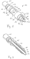
- FIG. 1 a connector arrangement 10 according to an embodiment of the present invention is shown.
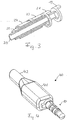
- Figs. 2 and 3 show portions of the embodiment of Fig. 1
- Fig. 4 shows the connector arrangement 10 incorporated in a connector 40 according to an embodiment.
- the connector arrangement shown in Fig. 1 apart from portions 31, 32 which will be described later has the form of a standard TRRS (tip ring ring sleeve) connector, for example the form of a 3.5 mm connector, a 2.5 mm connector or a 6.35 mm connector.
- TRRS tip ring ring sleeve
- the connector arrangement of Fig. 1 has more individual contact elements, i.e. elements which may individually serve for transmission of signals, than conventional TRRS connectors.
- Connector arrangement 10 of the embodiment of Fig. 1 comprises a tip portion or tip contact 11.
- Tip contact 11 may be electrically contacted via a rod-like portion 12 which is electrically coupled with tip contact 11.
- tip contact 11 and rod-like portion 12 may be made of a metal or other conducting material.
- Tip contact 11 is insulated via an insulating portion 25 from a first ring area which comprises a contact element 13, a contact element 19 and an insulator 26 electrically insulating contact elements 13 and 19 from each other.
- Contact element 13 may be electrically contacted via a contact portion 14, and contact element 19 may be electrically contacted via a contact portion 20.
- Contact elements 13 and 19 as well as portions 14 and 20 may be made of a metal, while insulator 26 may be made of a plastic material.
- portions of insulator 26 run parallel to insulator 25, i.e. parallel to a boundary of the first ring area, but other portions of insulator 26 run perpendicular to the direction of insulator 25, i.e.
- First ring portion is insulated by a ring-shaped insulator 27 which may again be made of a plastic material from a second ring portion, the second ring portion comprising a contact element 15 which may be electrically contacted via a contact portion 16, a contact element 21 which may be electrically contacted via a contact portion 22 and an insulator 28 electrically insulating contact element 15 from contact element 21.
- the configuration of the second ring area comprising contact elements 15, 21 and insulator 28 is similar to the configuration of first ring area comprising contact elements 13, 19 and insulator 26 and will therefore not be described again in detail.
- the second ring area is separated by an insulator 29 from a sleeve area (which also has a ring form and therefore may also be regarded as a ring area) comprising a contact element 17, a contact element 23 and an insulator 30.
- Ring-shaped insulator 29 and insulator 30 may be made of plastic and may be formed jointly, and contact elements 17 and 23 may be made of a metal.
- Contact element 17 may be electrically contacted via a contact portion 18, and contact element 23 may be electrically contacted via a contact portion 24.
- insulator 30 (which is also provided on the opposite side of connector arrangement 10 which is not visible in Fig. 1 in order to provide a complete insulation between contact elements 17 and 23) runs perpendicular to insulator 29, i.e. insulator 29 runs in a circumferential direction, and insulator 30 runs in a longitudinal direction of connector arrangement 10.
- connector arrangement 10 of the embodiment of Fig. 1 comprises a ring portion 31 with a protrusion 32 which both may be made of an insulating material, for example a plastic material.
- Protrusion 32 facilitates orientating connector arrangement 10 correctly when connector arrangement 10 is inserted in a corresponding receptacle, an example for which will be described further below with respect to Fig. 5 .
- tip contact 11, contact element 13 of the first ring area, contact element 15 of the second ring area and contact element 17 of the sleeve area may be used for the same purpose as a conventional TRRS connector, i.e. for stereo audio with an additional signal, for example a video signal.
- Contact elements 19, 21, and 23 may be used to transmit additional signals, for example to provide an additional power supply, to provide a contact for an antenna and/or to transmit data.
- the use of connector arrangement 10 of the embodiment of Fig. 1 or of other embodiments of the present invention is not limited to these signals, and the contact elements 13, 15, 17, 19, 21 and 23 and tip contact 11 may be used to establish an electrical connection for any desired kinds of signals.
- FIG. 2 The arrangement of the conducting portions of connector arrangement 10, which may for example be made of metal, are depicted in Figs. 2 and 3 without the insulating portions.
- Fig. 2 the portions defining tip connector 11, contact elements 13, 15, 17 and portions 12, 14, 16 and 18 are shown.
- the contact elements and contact portions for contacting them are arranged in a shell-like manner with the rod portion 12 in the center and portions 14, 16 and 18 surrounding rod portion 12 in a shell-like manner with an almost semicircular cross section (semicircular apart from spacing needed to be distanced from portions 20, 22 and 24) in this embodiment.
- Contact elements 13 and 15 in the embodiments shown comprise ring-shaped portions.
- rod portion 12 is connected to tip portion 11 by extending the rod portion throughout the connector, and contact portions 14, 16 and 18 are connected with contact elements 13, 15 and 17 by extending the respective contact portions 14, 16 and 18 through the connector up to the respective contact elements 13, 15 and 17.
- contact elements 19, 21 and 23 as well as of contact portions 20, 22 and 24 are shown.
- contact elements 19 and 21 comprise ring portions.
- Contact portions 20, 22 and 24 are arranged in a shell-like manner with an almost semicircular cross section and extend to the respective contact elements 19, 21 and 23 for electrically contacting the same.
- connector arrangement 10 of Fig. 1 for manufacturing connector arrangement 10 of Fig. 1 , the portions shown in Fig. 2 and Fig. 3 are placed together in an injection molding form and are then overmolded with a plastic material for forming the insulating portions 25, 26, 27, 28, 29 and 30 and/or portions 31, 32.
- the ring portions of contact elements 13, 15, 19 and 21 shown in Figs. 2 and 3 facilitate the placement of the conducting elements in such an injection molding form.
- insulating material is also filled in between contact portions 12, 14, 16, 18, 10, 22 and 24 in order to surely insulate them from each other.
- all insulating portions of the connector arrangement may be molded as one piece. Also, in other embodiments, all insulating portions may be provided as one single piece.
- some or all of the insulating portions may be provided as separate pieces.
- the above-explained method of injection molding serves only as an example, and other manufacturing methods, for example a separate manufacturing of an insulation part and the combination with conducting parts thereafter, is equally possible.
- Plug 40 incorporating connector arrangement 10 explained with reference to Figs. 1-3 is shown.
- Plug 40 comprises a housing 41 at an end of which connector arrangement 10 is mounted, and a cable 42 comprising a plurality of wires (not shown since they are within cable 42) for electrically contacting connector arrangement 10.
- the wires may be soldered or otherwise electrically connected with contact portions 12, 14, 16, 18, 20, 22 and 24.
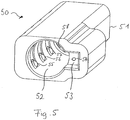
- a receptacle 50 for receiving a connector arrangement according to an embodiment of the present invention, for example connector arrangement 10 shown in Fig. 1 , for example incorporated in plug 40 shown in Fig. 4 , is shown.
- Receptacle 50 shown in Fig. 5 comprises a housing 51.
- Housing 51 may be part of a housing of an electronic device, for example a portable music player, a mobile phone, a laptop computer or a personal digital assistant (PDA).
- Housing 51 comprises an elongate hole 52 for receiving the connector arrangement and a cut-out 53 for receiving a protrusion of the connector arrangement, for example protrusion 32 of the embodiment of Fig. 1 , to ensure the correct orientation of the connector arrangement.
- contacts are provided corresponding to the contact elements of the connector arrangement.
- four contacts 55, 56, 57 and 58 are at least partially visible.
- contacts 55, 56 and 57 contact contact elements 23, 21 and 19, respectively, to establish an electrical connection and contact 58 may contact tip contact 11 to establish an electrical connection.
- Further contacts which in the perspective view of Fig. 5 are not visible and may for example be arranged opposed to contacts 55, 56, 57 in elongate hole 52 serve for contacting contact elements 17, 15 and 13 to establish electrical contact therewith.
- the connector arrangement has the form of a standard audio connector, for example a standard 3.5 mm audio connector.
- a corresponding receptacle like receptacle 50 of Fig. 5 may comprise some sensor 54, for example a mechanical sensor or an optical sensor, to detect the presence of protrusion 32 or a similar protrusion within cut out 53.
- sensor 54 does not detect the presence of a protrusion, and for example only those contacts of contacts 55, 56, 57, 58 and possibly other contacts provided with elongated hole 52 may be activated which serve for establishing a standard audio or video connection as described in the introductory portion are activated. If, on the other hand, the presence of a protrusion is detected, all contacts may be activated to make use of all the contact elements provided on the contact arrangement.
- the type of audio connector i.e. conventional audio connector or audio connector according to an embodiment, may be detected by sending specific signals on specific contacts and receiving a corresponding response from the connected device, for example ear phone or loudspeaker, coupled to the connector arrangement.
- a tip portion, a first ring portion, a second ring portion and a sleeve portion are provided for responding to the form of a TRRS-connector, in other embodiments only a single ring portion or no ring portion may be provided.
- insulators 26, 28 and 30 run either parallel to the insulating portions 25, 27, 29, i.e. parallel to the boundaries of the ring areas, or perpendicular thereto
- portions of the insulators separating the contact elements within a ring area or within the sleeve area may comprise portions forming any other non-zero angle with the boundary of the ring portions and sleeve portions, respectively.
- more than two contact elements may be provided within a ring area or within a sleeve area by providing corresponding insulations.
- first ring area and the second ring area are designed in a similar manner regarding the positioning of the insulating portion and the partitioning in contact elements, in other embodiments different partitionings and positions and form of the insulating portions may be used.
- tip contact 11 may be partitioned in two or more contact elements using an insulator. While in the embodiment of Fig.1 connector arrangement 10 has the form of a standard audio connector, in other embodiments other forms corresponding to an elongate member having a ring area may be used. For orientating connector arrangement 10, in Fig. 1 a protrusion 32 is shown. In other embodiments, the protrusion may have another form, more than one protrusion or other ridge or wedge-like members may be provided, or also a slit or groove matching with a corresponding protrusion in a receptacle may be provided. The electrical contact to the contact elements of the connector arrangement may be ensured in a different way than explained with reference to Figs. 2 and 3 , for example via wires soldered to the contact elements.
- protrusion 32 may be removable in order to be able to insert connector arrangement 10 in a standard audio connector socket.
- a receptacle like receptacle 50 may be modified corresponding to the modification discussed above for the connector arrangement in order to match with the connector arrangement and be able to receive and electrically contact the same.
Landscapes
- Details Of Connecting Devices For Male And Female Coupling (AREA)
- Coupling Device And Connection With Printed Circuit (AREA)
Claims (18)
- Agencement de connecteur audio (10), comprenant :un organe allongé avec une extrémité de pointe et une extrémité de manchon, l'organe allongé comprenant :au moins une zone de bague isolée électriquement de la surface restante de l'organe allongé via un ou plusieurs isolateurs en forme de bague (25, 27, 29), ladite au moins une zone de bague comprenant au moins un premier élément de contact (13, 15, 17) et un second élément de contact (19, 21, 23) isolés électriquement l'un de l'autre via une isolation (26, 28, 30), dans lequel au moins une portion de l'isolation (26, 28, 30) entre le premier élément de contact (13, 15, 17) et le second élément de contact (19, 21, 23) se présente dans une direction formant un angle non nul avec une direction d'une limite de l'au moins une zone de bague, l'isolateur en forme de bague et l'isolation n'étant pas connectés et étant espacés l'un de l'autre.
- Agencement de connecteur audio selon la revendication 1, dans lequel le connecteur audio est choisi dans le groupe constitué d'un connecteur audio de 3,5 mm, un connecteur audio de 2,5 mm et un connecteur audio de 6,35 mm.
- Agencement de connecteur audio selon l'une quelconque des revendications 1 ou 2, dans lequel ladite au moins une zone de bague comprend une pluralité de zones de bague.
- Agencement de connecteur audio selon la revendication 3, dans lequel ladite pluralité de zones de bague comprend une première zone de bague, une deuxième zone de bague et une troisième zone de bague, ladite troisième zone de bague étant agencée au niveau de ladite extrémité de manchon dudit connecteur pour former une zone de manchon, chacune desdites première zone de bague, deuxième zone de bague, et troisième zone de bague comprenant un premier élément de contact (13, 15, 17) et un second élément de contact (19, 21, 23).
- Agencement de connecteur audio selon l'une quelconque des revendications 1 à 4, comprenant en outre un contact de pointe (11) au niveau de ladite extrémité de pointe.
- Agencement de connecteur audio selon l'une quelconque des revendications 1 à 5, dans lequel ledit organe allongé comprend un premier élément conducteur définissant ledit premier élément de contact (13, 15, 17),
un second élément conducteur définissant ledit second élément de contact (19, 21, 23), et
un matériau isolant remplissant des interstices entre ledit premier élément conducteur et ledit second élément conducteur. - Agencement de connecteur audio selon la revendication 6, dans lequel ledit premier élément conducteur et ledit second élément conducteur comprennent chacun au moins une portion en forme de bague.
- Agencement de connecteur audio selon l'une quelconque des revendications 1 à 7, comprenant en outre un élément de guidage configuré pour aider l'insertion de l'agencement de connecteur (10) dans un réceptacle avec une orientation définie.
- Agencement de connecteur audio (10) selon la revendication 8, dans lequel l'élément de guidage comprend au moins un élément choisi dans le groupe constitué d'une protubérance (32), d'une crête, d'une fente et d'une gorge.
- Réceptacle (41 ; 51) pour un agencement de connecteur audio (10), comprenant :un trou allongé (52) configuré pour recevoir un organe allongé ayant la forme d'un connecteur audio,au moins deux contacts agencés au sein d'une section de bague dudit trou allongé (52) pour connecter les premier et second éléments de contact (19, 21, 23, 55, 56, 57) d'un agencement de connecteur concordant, lesdits premier et second éléments de contact (19, 21, 23) étant agencés au sein d'une section de bague dudit connecteur,l'agencement de connecteur comprenant :un organe allongé avec une extrémité de pointe et une extrémité de manchon, l'organe allongé comprenant :au moins une zone de bague isolée électriquement de la surface restante de l'organe allongé via un ou plusieurs isolateurs en forme de bague (25, 27, 29), ladite au moins une zone de bague comprenant au moins un premier élément de contact (13, 15, 17) et un second élément de contact (19, 21, 23) isolés électriquement l'un de l'autre via une isolation (26, 28, 30), dans lequel au moins une portion de l'isolation (26, 28, 30) entre le premier élément de contact (13, 15, 17) et le second élément de contact (19, 21, 23) se présente dans une direction formant un angle non nul avec une direction d'une limite de l'au moins une zone de bague, l'isolateur en forme de bague et l'isolation n'étant pas connectés et étant espacés l'un de l'autre.
- Réceptacle (41 ; 51) selon la revendication 10, comprenant en outre un élément de guidage configuré pour fournir une orientation définie pour l'insertion de l'agencement de connecteur (10) dans le réceptacle (41 ; 51).
- Réceptacle (41 ; 51) selon la revendication 11, dans lequel ledit élément de guidage comprend au moins un élément choisi dans le groupe constitué d'une découpe, d'une crête, d'une gorge, d'une fente et d'une protubérance (32).
- Réceptacle (41 ; 51) selon la revendication 11 ou 12, comprenant en outre un capteur (54) configuré pour détecter un couplage d'un élément de guidage supplémentaire d'un agencement de connecteur (10) avec ledit élément de guidage.
- Procédé de fabrication d'un connecteur audio ayant un organe allongé avec une extrémité de pointe et une extrémité de manchon, le procédé comprenant :la fourniture d'un premier élément conducteur définissant un premier élément de contact (13, 15, 17) sur une surface dudit organe allongé,la fourniture d'un second élément conducteur définissant un second élément de contact (19, 21, 23) sur la surface dudit organe allongé,la mise en place dudit premier élément conducteur et dudit second élément conducteur dans une forme de moulage de sorte que ladite première zone de contact et ladite seconde zone de contact soient positionnées au sein d'une zone de bague sur la surface dudit organe allongé, dans lequel une portion d'une limite entre la première zone de contact et la seconde zone de contact se présente dans une direction formant un angle non nul avec une limite de la zone de bague,le dépôt d'un matériau isolant pour remplir la zone de bague de sorte que la zone de bague soit isolée électriquement de la surface restante de l'organe allongé via un ou plusieurs isolateurs en forme de bague (25, 27, 29), etle dépôt d'un matériau isolant (26, 28, 30) entre ledit premier élément conducteur et ledit second élément conducteur à l'aide d'une technique de moulage de sorte que le premier élément conducteur et le second élément conducteur soient isolés électriquement l'un de l'autre via une isolation, dans lequel l'isolateur en forme de bague et l'isolation ne sont pas connectés et sont espacés l'un de l'autre.
- Agencement de connecteur audio (10) selon la revendication 1, dans lequel l'au moins une portion de l'isolation (26, 28, 30) se présente perpendiculaire à la circonférence des un ou plusieurs isolateurs en forme de bague (25, 27, 29).
- Agencement de connecteur audio (10) selon la revendication 15, dans lequel au moins une autre portion de l'isolation (26, 28, 30) différente de l'au moins une portion de l'isolation se présente parallèle à la circonférence des un ou plusieurs isolateurs en forme de bague (25, 27, 29).
- Agencement de connecteur audio (10) selon la revendication 1, dans lequel l'isolation (26, 28, 30) est interposée entre les un ou plusieurs isolateurs en forme de bague (25, 27, 29).
- Agencement de connecteur audio (10) selon la revendication 1, dans lequel l'isolateur en forme de bague (25, 27, 29) et l'isolation (26, 28, 30) sont des isolateurs séparés.
Applications Claiming Priority (2)
| Application Number | Priority Date | Filing Date | Title |
|---|---|---|---|
| US12/431,798 US8206181B2 (en) | 2009-04-29 | 2009-04-29 | Connector arrangement |
| PCT/EP2009/007750 WO2010124711A1 (fr) | 2009-04-29 | 2009-10-29 | Agencement de connecteur |
Publications (2)
| Publication Number | Publication Date |
|---|---|
| EP2425502A1 EP2425502A1 (fr) | 2012-03-07 |
| EP2425502B1 true EP2425502B1 (fr) | 2017-01-11 |
Family
ID=41508177
Family Applications (1)
| Application Number | Title | Priority Date | Filing Date |
|---|---|---|---|
| EP09753024.0A Not-in-force EP2425502B1 (fr) | 2009-04-29 | 2009-10-29 | Agencement de connecteur |
Country Status (4)
| Country | Link |
|---|---|
| US (1) | US8206181B2 (fr) |
| EP (1) | EP2425502B1 (fr) |
| CN (1) | CN102414938A (fr) |
| WO (1) | WO2010124711A1 (fr) |
Cited By (15)
| Publication number | Priority date | Publication date | Assignee | Title |
|---|---|---|---|---|
| US10492010B2 (en) | 2015-12-30 | 2019-11-26 | Earlens Corporations | Damping in contact hearing systems |
| US10511913B2 (en) | 2008-09-22 | 2019-12-17 | Earlens Corporation | Devices and methods for hearing |
| US10516951B2 (en) | 2014-11-26 | 2019-12-24 | Earlens Corporation | Adjustable venting for hearing instruments |
| US10516950B2 (en) | 2007-10-12 | 2019-12-24 | Earlens Corporation | Multifunction system and method for integrated hearing and communication with noise cancellation and feedback management |
| US10516949B2 (en) | 2008-06-17 | 2019-12-24 | Earlens Corporation | Optical electro-mechanical hearing devices with separate power and signal components |
| US10531206B2 (en) | 2014-07-14 | 2020-01-07 | Earlens Corporation | Sliding bias and peak limiting for optical hearing devices |
| US10609492B2 (en) | 2010-12-20 | 2020-03-31 | Earlens Corporation | Anatomically customized ear canal hearing apparatus |
| US10779094B2 (en) | 2015-12-30 | 2020-09-15 | Earlens Corporation | Damping in contact hearing systems |
| US11058305B2 (en) | 2015-10-02 | 2021-07-13 | Earlens Corporation | Wearable customized ear canal apparatus |
| US11102594B2 (en) | 2016-09-09 | 2021-08-24 | Earlens Corporation | Contact hearing systems, apparatus and methods |
| US11166114B2 (en) | 2016-11-15 | 2021-11-02 | Earlens Corporation | Impression procedure |
| US11212626B2 (en) | 2018-04-09 | 2021-12-28 | Earlens Corporation | Dynamic filter |
| US11317224B2 (en) | 2014-03-18 | 2022-04-26 | Earlens Corporation | High fidelity and reduced feedback contact hearing apparatus and methods |
| US11350226B2 (en) | 2015-12-30 | 2022-05-31 | Earlens Corporation | Charging protocol for rechargeable hearing systems |
| US11516603B2 (en) | 2018-03-07 | 2022-11-29 | Earlens Corporation | Contact hearing device and retention structure materials |
Families Citing this family (22)
| Publication number | Priority date | Publication date | Assignee | Title |
|---|---|---|---|---|
| US7182738B2 (en) | 2003-04-23 | 2007-02-27 | Marctec, Llc | Patient monitoring apparatus and method for orthosis and other devices |
| US7589536B2 (en) | 2007-01-05 | 2009-09-15 | Apple Inc. | Systems and methods for determining the configuration of electronic connections |
| US8655006B2 (en) | 2010-01-25 | 2014-02-18 | Apple Inc. | Multi-segment cable structures |
| US8435081B2 (en) * | 2010-03-31 | 2013-05-07 | Apple Inc. | Thin plug assembly and methods for making the same |
| EP2577813B1 (fr) | 2010-05-28 | 2020-01-22 | Apple Inc. | Connecteur à double orientation à contacts externes |
| DE202010009766U1 (de) * | 2010-07-02 | 2010-09-16 | Rosenberger Hochfrequenztechnik Gmbh & Co. Kg | Drehbarer Steckverbinder |
| US8446275B2 (en) | 2011-06-10 | 2013-05-21 | Aliphcom | General health and wellness management method and apparatus for a wellness application using data from a data-capable band |
| US9069380B2 (en) | 2011-06-10 | 2015-06-30 | Aliphcom | Media device, application, and content management using sensory input |
| US9258670B2 (en) | 2011-06-10 | 2016-02-09 | Aliphcom | Wireless enabled cap for a data-capable device |
| US20120315382A1 (en) * | 2011-06-10 | 2012-12-13 | Aliphcom | Component protective overmolding using protective external coatings |
| US9293876B2 (en) | 2011-11-07 | 2016-03-22 | Apple Inc. | Techniques for configuring contacts of a connector |
| US8799527B2 (en) | 2012-09-07 | 2014-08-05 | Apple Inc. | Data structures for facilitating communication between a host device and an accessory |
| US8891216B2 (en) | 2012-04-25 | 2014-11-18 | Apple Inc. | Techniques for detecting removal of a connector |
| US8724281B2 (en) | 2012-04-25 | 2014-05-13 | Apple Inc. | Techniques for detecting removal of a connector |
| US10043535B2 (en) | 2013-01-15 | 2018-08-07 | Staton Techiya, Llc | Method and device for spectral expansion for an audio signal |
| US9205905B2 (en) * | 2013-03-15 | 2015-12-08 | Jlip, Llc | Waterproof rotary contact assembly |
| US9307312B2 (en) | 2013-03-15 | 2016-04-05 | Apple Inc. | Audio accessory with internal clock |
| US10045135B2 (en) | 2013-10-24 | 2018-08-07 | Staton Techiya, Llc | Method and device for recognition and arbitration of an input connection |
| JP6580991B2 (ja) * | 2013-11-22 | 2019-09-25 | ソニーセミコンダクタソリューションズ株式会社 | 接続装置および受信装置 |
| US10043534B2 (en) | 2013-12-23 | 2018-08-07 | Staton Techiya, Llc | Method and device for spectral expansion for an audio signal |
| CN205752715U (zh) * | 2016-03-31 | 2016-11-30 | 深圳贝尔创意科教有限公司 | 连接结构及应用该连接结构的电子装置 |
| EP3285339B1 (fr) * | 2016-06-16 | 2019-07-24 | Nippon Dics Co., Ltd. | Fiche multipolaire |
Citations (1)
| Publication number | Priority date | Publication date | Assignee | Title |
|---|---|---|---|---|
| EP1898499A2 (fr) * | 2006-09-08 | 2008-03-12 | Sony Corporation | Fiche mâle |
Family Cites Families (15)
| Publication number | Priority date | Publication date | Assignee | Title |
|---|---|---|---|---|
| JPS5736790A (fr) * | 1980-08-13 | 1982-02-27 | Olympus Optical Co | |
| US5550755A (en) | 1994-07-14 | 1996-08-27 | Martin; B. Morgan | Apparatus and method for patch recording and recall |
| US6981895B2 (en) * | 1999-08-23 | 2006-01-03 | Patrick Potega | Interface apparatus for selectively connecting electrical devices |
| US6461199B1 (en) * | 2001-06-12 | 2002-10-08 | Nobutaka Koga | Multiple electrode connecting apparatus |
| US6869316B2 (en) * | 2002-06-27 | 2005-03-22 | Dell Products L.P. | Three contact barrel power connector assembly |
| TWI256755B (en) * | 2002-11-29 | 2006-06-11 | Hon Hai Prec Ind Co Ltd | Method for assembling electrical connector |
| US6764347B1 (en) * | 2003-01-06 | 2004-07-20 | Paul J. Plishner | Plug and socket holder for replaceably holding diode-based light sources and other radiation sources and receivers |
| DE202004006906U1 (de) | 2004-04-29 | 2004-10-21 | Schmitz, Martin | Netzstecker und Netzsteckdose mit Schutzkontakt |
| US7641520B2 (en) * | 2004-08-27 | 2010-01-05 | Pmi Industries, Inc. | Flexible connector assembly |
| US7950967B2 (en) * | 2008-01-18 | 2011-05-31 | Apple Inc. | Low profile plugs |
| JP4690842B2 (ja) * | 2005-10-03 | 2011-06-01 | ルネサスエレクトロニクス株式会社 | 通信ケーブルのコネクタ及び通信ケーブル |
| JP4971857B2 (ja) * | 2007-03-29 | 2012-07-11 | 富士通コンポーネント株式会社 | コネクタ装置 |
| JP4389984B2 (ja) * | 2007-08-31 | 2009-12-24 | 株式会社カシオ日立モバイルコミュニケーションズ | 防水コネクタ構造、ジャック部品、電子機器及びプラグ部品 |
| US7699665B1 (en) * | 2008-10-31 | 2010-04-20 | Cheng Uei Precision Industry Co., Ltd. | Audio plug connector |
| CN101800375B (zh) * | 2009-02-07 | 2012-06-20 | 富士康(昆山)电脑接插件有限公司 | 插座连接器及与其配合的插头连接器 |
-
2009
- 2009-04-29 US US12/431,798 patent/US8206181B2/en not_active Expired - Fee Related
- 2009-10-29 CN CN2009801590111A patent/CN102414938A/zh active Pending
- 2009-10-29 WO PCT/EP2009/007750 patent/WO2010124711A1/fr not_active Ceased
- 2009-10-29 EP EP09753024.0A patent/EP2425502B1/fr not_active Not-in-force
Patent Citations (1)
| Publication number | Priority date | Publication date | Assignee | Title |
|---|---|---|---|---|
| EP1898499A2 (fr) * | 2006-09-08 | 2008-03-12 | Sony Corporation | Fiche mâle |
Cited By (32)
| Publication number | Priority date | Publication date | Assignee | Title |
|---|---|---|---|---|
| US11483665B2 (en) | 2007-10-12 | 2022-10-25 | Earlens Corporation | Multifunction system and method for integrated hearing and communication with noise cancellation and feedback management |
| US10863286B2 (en) | 2007-10-12 | 2020-12-08 | Earlens Corporation | Multifunction system and method for integrated hearing and communication with noise cancellation and feedback management |
| US10516950B2 (en) | 2007-10-12 | 2019-12-24 | Earlens Corporation | Multifunction system and method for integrated hearing and communication with noise cancellation and feedback management |
| US10516949B2 (en) | 2008-06-17 | 2019-12-24 | Earlens Corporation | Optical electro-mechanical hearing devices with separate power and signal components |
| US11310605B2 (en) | 2008-06-17 | 2022-04-19 | Earlens Corporation | Optical electro-mechanical hearing devices with separate power and signal components |
| US10743110B2 (en) | 2008-09-22 | 2020-08-11 | Earlens Corporation | Devices and methods for hearing |
| US10516946B2 (en) | 2008-09-22 | 2019-12-24 | Earlens Corporation | Devices and methods for hearing |
| US11057714B2 (en) | 2008-09-22 | 2021-07-06 | Earlens Corporation | Devices and methods for hearing |
| US10511913B2 (en) | 2008-09-22 | 2019-12-17 | Earlens Corporation | Devices and methods for hearing |
| US10609492B2 (en) | 2010-12-20 | 2020-03-31 | Earlens Corporation | Anatomically customized ear canal hearing apparatus |
| US11743663B2 (en) | 2010-12-20 | 2023-08-29 | Earlens Corporation | Anatomically customized ear canal hearing apparatus |
| US11153697B2 (en) | 2010-12-20 | 2021-10-19 | Earlens Corporation | Anatomically customized ear canal hearing apparatus |
| US11317224B2 (en) | 2014-03-18 | 2022-04-26 | Earlens Corporation | High fidelity and reduced feedback contact hearing apparatus and methods |
| US10531206B2 (en) | 2014-07-14 | 2020-01-07 | Earlens Corporation | Sliding bias and peak limiting for optical hearing devices |
| US11800303B2 (en) | 2014-07-14 | 2023-10-24 | Earlens Corporation | Sliding bias and peak limiting for optical hearing devices |
| US11259129B2 (en) | 2014-07-14 | 2022-02-22 | Earlens Corporation | Sliding bias and peak limiting for optical hearing devices |
| US11252516B2 (en) | 2014-11-26 | 2022-02-15 | Earlens Corporation | Adjustable venting for hearing instruments |
| US10516951B2 (en) | 2014-11-26 | 2019-12-24 | Earlens Corporation | Adjustable venting for hearing instruments |
| US11058305B2 (en) | 2015-10-02 | 2021-07-13 | Earlens Corporation | Wearable customized ear canal apparatus |
| US11350226B2 (en) | 2015-12-30 | 2022-05-31 | Earlens Corporation | Charging protocol for rechargeable hearing systems |
| US11070927B2 (en) | 2015-12-30 | 2021-07-20 | Earlens Corporation | Damping in contact hearing systems |
| US11337012B2 (en) | 2015-12-30 | 2022-05-17 | Earlens Corporation | Battery coating for rechargable hearing systems |
| US11516602B2 (en) | 2015-12-30 | 2022-11-29 | Earlens Corporation | Damping in contact hearing systems |
| US10779094B2 (en) | 2015-12-30 | 2020-09-15 | Earlens Corporation | Damping in contact hearing systems |
| US10492010B2 (en) | 2015-12-30 | 2019-11-26 | Earlens Corporations | Damping in contact hearing systems |
| US11102594B2 (en) | 2016-09-09 | 2021-08-24 | Earlens Corporation | Contact hearing systems, apparatus and methods |
| US11540065B2 (en) | 2016-09-09 | 2022-12-27 | Earlens Corporation | Contact hearing systems, apparatus and methods |
| US11166114B2 (en) | 2016-11-15 | 2021-11-02 | Earlens Corporation | Impression procedure |
| US11671774B2 (en) | 2016-11-15 | 2023-06-06 | Earlens Corporation | Impression procedure |
| US11516603B2 (en) | 2018-03-07 | 2022-11-29 | Earlens Corporation | Contact hearing device and retention structure materials |
| US11212626B2 (en) | 2018-04-09 | 2021-12-28 | Earlens Corporation | Dynamic filter |
| US11564044B2 (en) | 2018-04-09 | 2023-01-24 | Earlens Corporation | Dynamic filter |
Also Published As
| Publication number | Publication date |
|---|---|
| US8206181B2 (en) | 2012-06-26 |
| CN102414938A (zh) | 2012-04-11 |
| US20100279554A1 (en) | 2010-11-04 |
| WO2010124711A1 (fr) | 2010-11-04 |
| EP2425502A1 (fr) | 2012-03-07 |
Similar Documents
| Publication | Publication Date | Title |
|---|---|---|
| EP2425502B1 (fr) | Agencement de connecteur | |
| EP2301118B1 (fr) | Agencement de connecteur | |
| US6126465A (en) | Electrical connector system having dual purpose jack | |
| CN106229725B (zh) | 模块化射频连接器系统 | |
| US8911260B2 (en) | External contact plug connector | |
| CN103081253B (zh) | 插塞连接器和插座连接器 | |
| US8235756B2 (en) | Low profile plugs | |
| KR101536888B1 (ko) | 자기력으로 고정되는 휴대용 단말기의 충전 장치 | |
| US20150333458A1 (en) | Releasable plug connector system | |
| US20130244485A1 (en) | Serial electrical connector | |
| TW201725813A (zh) | 轉接器 | |
| US8430690B2 (en) | USB application device and method for assembling USB application device | |
| US10103505B1 (en) | Cable with connectors | |
| EP2595464A2 (fr) | Dispositif d'application USB et procédé d'assemblage de dispositif d'application USB | |
| CN106299822A (zh) | 接口的成型胶芯的加工方法 | |
| KR102821144B1 (ko) | 비대칭 삽입력-대-추출력 비를 갖는 전력 커넥터 | |
| CN202308687U (zh) | 电连接器插座、电连接器插头及电连接器总成 | |
| US8698699B2 (en) | Connector | |
| CN217468973U (zh) | 具有导引结构的连接器组及其插头连接器与插座连接器 | |
| TWI415347B (zh) | 小型插塞及用於裝配其之方法 | |
| US20180151971A1 (en) | Internal and External Connector and Receptacle | |
| CN205376845U (zh) | 一种具有新型触针组件的连接器 | |
| CN101107754A (zh) | 回路插头 | |
| JP3097615U (ja) | 携帯電話用アダプタ | |
| TWM560132U (zh) | 複合型轉接頭結構 |
Legal Events
| Date | Code | Title | Description |
|---|---|---|---|
| PUAI | Public reference made under article 153(3) epc to a published international application that has entered the european phase |
Free format text: ORIGINAL CODE: 0009012 |
|
| 17P | Request for examination filed |
Effective date: 20111027 |
|
| AK | Designated contracting states |
Kind code of ref document: A1 Designated state(s): AT BE BG CH CY CZ DE DK EE ES FI FR GB GR HR HU IE IS IT LI LT LU LV MC MK MT NL NO PL PT RO SE SI SK SM TR |
|
| DAX | Request for extension of the european patent (deleted) | ||
| 17Q | First examination report despatched |
Effective date: 20120817 |
|
| RAP1 | Party data changed (applicant data changed or rights of an application transferred) |
Owner name: SONY MOBILE COMMUNICATIONS AB |
|
| RAP1 | Party data changed (applicant data changed or rights of an application transferred) |
Owner name: SNAPTRACK, INC. |
|
| REG | Reference to a national code |
Ref country code: DE Ref legal event code: R079 Ref document number: 602009043711 Country of ref document: DE Free format text: PREVIOUS MAIN CLASS: H01R0024020000 Ipc: H01R0024580000 |
|
| GRAP | Despatch of communication of intention to grant a patent |
Free format text: ORIGINAL CODE: EPIDOSNIGR1 |
|
| RIC1 | Information provided on ipc code assigned before grant |
Ipc: H01R 24/58 20110101AFI20160706BHEP |
|
| INTG | Intention to grant announced |
Effective date: 20160729 |
|
| GRAS | Grant fee paid |
Free format text: ORIGINAL CODE: EPIDOSNIGR3 |
|
| GRAA | (expected) grant |
Free format text: ORIGINAL CODE: 0009210 |
|
| AK | Designated contracting states |
Kind code of ref document: B1 Designated state(s): AT BE BG CH CY CZ DE DK EE ES FI FR GB GR HR HU IE IS IT LI LT LU LV MC MK MT NL NO PL PT RO SE SI SK SM TR |
|
| REG | Reference to a national code |
Ref country code: GB Ref legal event code: FG4D |
|
| REG | Reference to a national code |
Ref country code: CH Ref legal event code: EP |
|
| REG | Reference to a national code |
Ref country code: AT Ref legal event code: REF Ref document number: 862074 Country of ref document: AT Kind code of ref document: T Effective date: 20170115 |
|
| REG | Reference to a national code |
Ref country code: IE Ref legal event code: FG4D |
|
| REG | Reference to a national code |
Ref country code: DE Ref legal event code: R096 Ref document number: 602009043711 Country of ref document: DE |
|
| REG | Reference to a national code |
Ref country code: LT Ref legal event code: MG4D |
|
| REG | Reference to a national code |
Ref country code: NL Ref legal event code: MP Effective date: 20170111 |
|
| REG | Reference to a national code |
Ref country code: AT Ref legal event code: MK05 Ref document number: 862074 Country of ref document: AT Kind code of ref document: T Effective date: 20170111 |
|
| PG25 | Lapsed in a contracting state [announced via postgrant information from national office to epo] |
Ref country code: NL Free format text: LAPSE BECAUSE OF FAILURE TO SUBMIT A TRANSLATION OF THE DESCRIPTION OR TO PAY THE FEE WITHIN THE PRESCRIBED TIME-LIMIT Effective date: 20170111 |
|
| PG25 | Lapsed in a contracting state [announced via postgrant information from national office to epo] |
Ref country code: GR Free format text: LAPSE BECAUSE OF FAILURE TO SUBMIT A TRANSLATION OF THE DESCRIPTION OR TO PAY THE FEE WITHIN THE PRESCRIBED TIME-LIMIT Effective date: 20170412 Ref country code: NO Free format text: LAPSE BECAUSE OF FAILURE TO SUBMIT A TRANSLATION OF THE DESCRIPTION OR TO PAY THE FEE WITHIN THE PRESCRIBED TIME-LIMIT Effective date: 20170411 Ref country code: HR Free format text: LAPSE BECAUSE OF FAILURE TO SUBMIT A TRANSLATION OF THE DESCRIPTION OR TO PAY THE FEE WITHIN THE PRESCRIBED TIME-LIMIT Effective date: 20170111 Ref country code: FI Free format text: LAPSE BECAUSE OF FAILURE TO SUBMIT A TRANSLATION OF THE DESCRIPTION OR TO PAY THE FEE WITHIN THE PRESCRIBED TIME-LIMIT Effective date: 20170111 Ref country code: LT Free format text: LAPSE BECAUSE OF FAILURE TO SUBMIT A TRANSLATION OF THE DESCRIPTION OR TO PAY THE FEE WITHIN THE PRESCRIBED TIME-LIMIT Effective date: 20170111 Ref country code: IS Free format text: LAPSE BECAUSE OF FAILURE TO SUBMIT A TRANSLATION OF THE DESCRIPTION OR TO PAY THE FEE WITHIN THE PRESCRIBED TIME-LIMIT Effective date: 20170511 |
|
| PG25 | Lapsed in a contracting state [announced via postgrant information from national office to epo] |
Ref country code: AT Free format text: LAPSE BECAUSE OF FAILURE TO SUBMIT A TRANSLATION OF THE DESCRIPTION OR TO PAY THE FEE WITHIN THE PRESCRIBED TIME-LIMIT Effective date: 20170111 Ref country code: PT Free format text: LAPSE BECAUSE OF FAILURE TO SUBMIT A TRANSLATION OF THE DESCRIPTION OR TO PAY THE FEE WITHIN THE PRESCRIBED TIME-LIMIT Effective date: 20170511 Ref country code: PL Free format text: LAPSE BECAUSE OF FAILURE TO SUBMIT A TRANSLATION OF THE DESCRIPTION OR TO PAY THE FEE WITHIN THE PRESCRIBED TIME-LIMIT Effective date: 20170111 Ref country code: BG Free format text: LAPSE BECAUSE OF FAILURE TO SUBMIT A TRANSLATION OF THE DESCRIPTION OR TO PAY THE FEE WITHIN THE PRESCRIBED TIME-LIMIT Effective date: 20170411 Ref country code: ES Free format text: LAPSE BECAUSE OF FAILURE TO SUBMIT A TRANSLATION OF THE DESCRIPTION OR TO PAY THE FEE WITHIN THE PRESCRIBED TIME-LIMIT Effective date: 20170111 Ref country code: SE Free format text: LAPSE BECAUSE OF FAILURE TO SUBMIT A TRANSLATION OF THE DESCRIPTION OR TO PAY THE FEE WITHIN THE PRESCRIBED TIME-LIMIT Effective date: 20170111 Ref country code: LV Free format text: LAPSE BECAUSE OF FAILURE TO SUBMIT A TRANSLATION OF THE DESCRIPTION OR TO PAY THE FEE WITHIN THE PRESCRIBED TIME-LIMIT Effective date: 20170111 |
|
| REG | Reference to a national code |
Ref country code: FR Ref legal event code: PLFP Year of fee payment: 9 |
|
| REG | Reference to a national code |
Ref country code: DE Ref legal event code: R097 Ref document number: 602009043711 Country of ref document: DE |
|
| PG25 | Lapsed in a contracting state [announced via postgrant information from national office to epo] |
Ref country code: CZ Free format text: LAPSE BECAUSE OF FAILURE TO SUBMIT A TRANSLATION OF THE DESCRIPTION OR TO PAY THE FEE WITHIN THE PRESCRIBED TIME-LIMIT Effective date: 20170111 Ref country code: SK Free format text: LAPSE BECAUSE OF FAILURE TO SUBMIT A TRANSLATION OF THE DESCRIPTION OR TO PAY THE FEE WITHIN THE PRESCRIBED TIME-LIMIT Effective date: 20170111 Ref country code: EE Free format text: LAPSE BECAUSE OF FAILURE TO SUBMIT A TRANSLATION OF THE DESCRIPTION OR TO PAY THE FEE WITHIN THE PRESCRIBED TIME-LIMIT Effective date: 20170111 Ref country code: IT Free format text: LAPSE BECAUSE OF FAILURE TO SUBMIT A TRANSLATION OF THE DESCRIPTION OR TO PAY THE FEE WITHIN THE PRESCRIBED TIME-LIMIT Effective date: 20170111 Ref country code: RO Free format text: LAPSE BECAUSE OF FAILURE TO SUBMIT A TRANSLATION OF THE DESCRIPTION OR TO PAY THE FEE WITHIN THE PRESCRIBED TIME-LIMIT Effective date: 20170111 |
|
| PLBE | No opposition filed within time limit |
Free format text: ORIGINAL CODE: 0009261 |
|
| STAA | Information on the status of an ep patent application or granted ep patent |
Free format text: STATUS: NO OPPOSITION FILED WITHIN TIME LIMIT |
|
| PG25 | Lapsed in a contracting state [announced via postgrant information from national office to epo] |
Ref country code: SM Free format text: LAPSE BECAUSE OF FAILURE TO SUBMIT A TRANSLATION OF THE DESCRIPTION OR TO PAY THE FEE WITHIN THE PRESCRIBED TIME-LIMIT Effective date: 20170111 Ref country code: DK Free format text: LAPSE BECAUSE OF FAILURE TO SUBMIT A TRANSLATION OF THE DESCRIPTION OR TO PAY THE FEE WITHIN THE PRESCRIBED TIME-LIMIT Effective date: 20170111 |
|
| 26N | No opposition filed |
Effective date: 20171012 |
|
| PG25 | Lapsed in a contracting state [announced via postgrant information from national office to epo] |
Ref country code: SI Free format text: LAPSE BECAUSE OF FAILURE TO SUBMIT A TRANSLATION OF THE DESCRIPTION OR TO PAY THE FEE WITHIN THE PRESCRIBED TIME-LIMIT Effective date: 20170111 |
|
| PG25 | Lapsed in a contracting state [announced via postgrant information from national office to epo] |
Ref country code: MC Free format text: LAPSE BECAUSE OF FAILURE TO SUBMIT A TRANSLATION OF THE DESCRIPTION OR TO PAY THE FEE WITHIN THE PRESCRIBED TIME-LIMIT Effective date: 20170111 |
|
| REG | Reference to a national code |
Ref country code: CH Ref legal event code: PL |
|
| REG | Reference to a national code |
Ref country code: IE Ref legal event code: MM4A |
|
| PG25 | Lapsed in a contracting state [announced via postgrant information from national office to epo] |
Ref country code: LI Free format text: LAPSE BECAUSE OF NON-PAYMENT OF DUE FEES Effective date: 20171031 Ref country code: CH Free format text: LAPSE BECAUSE OF NON-PAYMENT OF DUE FEES Effective date: 20171031 Ref country code: LU Free format text: LAPSE BECAUSE OF NON-PAYMENT OF DUE FEES Effective date: 20171029 |
|
| REG | Reference to a national code |
Ref country code: BE Ref legal event code: MM Effective date: 20171031 |
|
| PG25 | Lapsed in a contracting state [announced via postgrant information from national office to epo] |
Ref country code: BE Free format text: LAPSE BECAUSE OF NON-PAYMENT OF DUE FEES Effective date: 20171031 |
|
| REG | Reference to a national code |
Ref country code: FR Ref legal event code: PLFP Year of fee payment: 10 |
|
| PG25 | Lapsed in a contracting state [announced via postgrant information from national office to epo] |
Ref country code: MT Free format text: LAPSE BECAUSE OF NON-PAYMENT OF DUE FEES Effective date: 20171029 |
|
| PG25 | Lapsed in a contracting state [announced via postgrant information from national office to epo] |
Ref country code: IE Free format text: LAPSE BECAUSE OF NON-PAYMENT OF DUE FEES Effective date: 20171029 |
|
| PG25 | Lapsed in a contracting state [announced via postgrant information from national office to epo] |
Ref country code: HU Free format text: LAPSE BECAUSE OF FAILURE TO SUBMIT A TRANSLATION OF THE DESCRIPTION OR TO PAY THE FEE WITHIN THE PRESCRIBED TIME-LIMIT; INVALID AB INITIO Effective date: 20091029 |
|
| PG25 | Lapsed in a contracting state [announced via postgrant information from national office to epo] |
Ref country code: CY Free format text: LAPSE BECAUSE OF NON-PAYMENT OF DUE FEES Effective date: 20170111 |
|
| PGFP | Annual fee paid to national office [announced via postgrant information from national office to epo] |
Ref country code: FR Payment date: 20190924 Year of fee payment: 11 |
|
| PG25 | Lapsed in a contracting state [announced via postgrant information from national office to epo] |
Ref country code: MK Free format text: LAPSE BECAUSE OF FAILURE TO SUBMIT A TRANSLATION OF THE DESCRIPTION OR TO PAY THE FEE WITHIN THE PRESCRIBED TIME-LIMIT Effective date: 20170111 |
|
| PGFP | Annual fee paid to national office [announced via postgrant information from national office to epo] |
Ref country code: GB Payment date: 20190925 Year of fee payment: 11 |
|
| PGFP | Annual fee paid to national office [announced via postgrant information from national office to epo] |
Ref country code: DE Payment date: 20190917 Year of fee payment: 11 |
|
| PG25 | Lapsed in a contracting state [announced via postgrant information from national office to epo] |
Ref country code: TR Free format text: LAPSE BECAUSE OF FAILURE TO SUBMIT A TRANSLATION OF THE DESCRIPTION OR TO PAY THE FEE WITHIN THE PRESCRIBED TIME-LIMIT Effective date: 20170111 |
|
| REG | Reference to a national code |
Ref country code: DE Ref legal event code: R119 Ref document number: 602009043711 Country of ref document: DE |
|
| GBPC | Gb: european patent ceased through non-payment of renewal fee |
Effective date: 20201029 |
|
| PG25 | Lapsed in a contracting state [announced via postgrant information from national office to epo] |
Ref country code: FR Free format text: LAPSE BECAUSE OF NON-PAYMENT OF DUE FEES Effective date: 20201031 Ref country code: DE Free format text: LAPSE BECAUSE OF NON-PAYMENT OF DUE FEES Effective date: 20210501 |
|
| PG25 | Lapsed in a contracting state [announced via postgrant information from national office to epo] |
Ref country code: GB Free format text: LAPSE BECAUSE OF NON-PAYMENT OF DUE FEES Effective date: 20201029 |