EP2425474B1 - Ventilstopfen - Google Patents
Ventilstopfen Download PDFInfo
- Publication number
- EP2425474B1 EP2425474B1 EP10725002.9A EP10725002A EP2425474B1 EP 2425474 B1 EP2425474 B1 EP 2425474B1 EP 10725002 A EP10725002 A EP 10725002A EP 2425474 B1 EP2425474 B1 EP 2425474B1
- Authority
- EP
- European Patent Office
- Prior art keywords
- valve
- sealing surface
- plug
- valve plug
- surface section
- Prior art date
- Legal status (The legal status is an assumption and is not a legal conclusion. Google has not performed a legal analysis and makes no representation as to the accuracy of the status listed.)
- Active
Links
Images
Classifications
-
- F—MECHANICAL ENGINEERING; LIGHTING; HEATING; WEAPONS; BLASTING
- F16—ENGINEERING ELEMENTS AND UNITS; GENERAL MEASURES FOR PRODUCING AND MAINTAINING EFFECTIVE FUNCTIONING OF MACHINES OR INSTALLATIONS; THERMAL INSULATION IN GENERAL
- F16K—VALVES; TAPS; COCKS; ACTUATING-FLOATS; DEVICES FOR VENTING OR AERATING
- F16K15/00—Check valves
- F16K15/14—Check valves with flexible valve members
- F16K15/144—Check valves with flexible valve members the closure elements being fixed along all or a part of their periphery
-
- H—ELECTRICITY
- H01—ELECTRIC ELEMENTS
- H01M—PROCESSES OR MEANS, e.g. BATTERIES, FOR THE DIRECT CONVERSION OF CHEMICAL ENERGY INTO ELECTRICAL ENERGY
- H01M50/00—Constructional details or processes of manufacture of the non-active parts of electrochemical cells other than fuel cells, e.g. hybrid cells
- H01M50/30—Arrangements for facilitating escape of gases
- H01M50/317—Re-sealable arrangements
- H01M50/325—Re-sealable arrangements comprising deformable valve members, e.g. elastic or flexible valve members
-
- H—ELECTRICITY
- H01—ELECTRIC ELEMENTS
- H01M—PROCESSES OR MEANS, e.g. BATTERIES, FOR THE DIRECT CONVERSION OF CHEMICAL ENERGY INTO ELECTRICAL ENERGY
- H01M50/00—Constructional details or processes of manufacture of the non-active parts of electrochemical cells other than fuel cells, e.g. hybrid cells
- H01M50/60—Arrangements or processes for filling or topping-up with liquids; Arrangements or processes for draining liquids from casings
- H01M50/609—Arrangements or processes for filling with liquid, e.g. electrolytes
- H01M50/627—Filling ports
- H01M50/636—Closing or sealing filling ports, e.g. using lids
- H01M50/645—Plugs
- H01M50/655—Plugs specially adapted for venting
-
- H—ELECTRICITY
- H01—ELECTRIC ELEMENTS
- H01M—PROCESSES OR MEANS, e.g. BATTERIES, FOR THE DIRECT CONVERSION OF CHEMICAL ENERGY INTO ELECTRICAL ENERGY
- H01M10/00—Secondary cells; Manufacture thereof
- H01M10/06—Lead-acid accumulators
-
- Y—GENERAL TAGGING OF NEW TECHNOLOGICAL DEVELOPMENTS; GENERAL TAGGING OF CROSS-SECTIONAL TECHNOLOGIES SPANNING OVER SEVERAL SECTIONS OF THE IPC; TECHNICAL SUBJECTS COVERED BY FORMER USPC CROSS-REFERENCE ART COLLECTIONS [XRACs] AND DIGESTS
- Y02—TECHNOLOGIES OR APPLICATIONS FOR MITIGATION OR ADAPTATION AGAINST CLIMATE CHANGE
- Y02E—REDUCTION OF GREENHOUSE GAS [GHG] EMISSIONS, RELATED TO ENERGY GENERATION, TRANSMISSION OR DISTRIBUTION
- Y02E60/00—Enabling technologies; Technologies with a potential or indirect contribution to GHG emissions mitigation
- Y02E60/10—Energy storage using batteries
Definitions
- the invention relates to a valve plug for sealing a container opening with an attachable to the container opening valve body of a first, rigid plastic material and an integral with the valve body valve member connected from a second, elastic plastic material which is more elastic than the first plastic material, wherein the valve element on a a sealing surface portion which can be placed on the edge of the container opening and has a connecting part which holds the sealing surface portion in the desired position.
- valve plugs are used in particular for closing filling and inspection openings of accumulators, in particular of lead-acid batteries for motor vehicles.
- a gas outlet should be possible if an overpressure in the battery housing is formed.
- EP 1 194 962 B1 It is known to put an elastic cap on a pipe socket which limits a container opening of a battery cell. Above the elastic cap a separate lid is placed on the battery lid closing. At an overpressure gas can pass through the space between the pipe socket and elastic cap due to the elastic deformability of the elastic cap from the cell interior to the outside.
- EP 1 001 905 B1 discloses a sealing valve made of rubber-elastic material with a plug part, which in a container opening up to the plug part in the radial Direction superior stopper collar is inserted.
- At the plug part at least one control channel is formed by a recess in the plug part, which extends from an underside of the plug part in the direction of the longitudinal axis of the sealing valve to the plug collar.
- a sealing bead is formed, which is sealingly placed on a container edge enclosing the container opening.
- the control channel is continued in the plug part up to the sealing bead.
- DE 103 49 395 B3 shows a valve plug in which a valve made of an elastic material is integrally formed on a base body, so that the valve and the main body form a multi-component injection molded part.
- the integrally formed as a molded elastic valve has a valve body and a sealing flap formed thereon, which is thinner in cross-section than the valve body.
- the sealing flap is formed on the lower outer edge portion of the valve body and has the shape of a semicircular disc which abuts for sealing on the inner edge of a sleeve in the valve body.
- the publication WO 2003 / 057083A2 relates to a valve plug which is suitable for sealing a container opening.
- the valve plug known from this prior art has a valve body attachable to the valve body made of a first, rigid plastic material and an integral with the valve body valve member made of a second, elastic plastic material, wherein the second plastic material is more elastic than the first plastic material.
- the valve element has a sealing surface portion which can be placed tightly on a contact edge, and a connecting part which extends from the sealing surface portion radially through an opening in the valve body to a holding portion held on the outer circumference of the valve body.
- the sealing surface portion is not stopped by an axial support as in known valve stoppers, but significantly by an extending in the radial direction through the recess of the valve body Verbin dung part.
- a recess in the sealing surface portion is achieved that the resilient region is softer there than in the remaining peripheral region of the sealing surface portion pressing on the contact edge connecting part.
- the defined response is also ensured by a sealing lip, through which the risk of sticking of the sealing surface portion is reduced with the contact edge of the container opening.
- the recess may advantageously be formed as a ring segment-shaped slot.
- the connecting part holds the sealing surface portion fixed to the valve body, so that the sealing surface portion in the region of the connecting part does not yield or only slightly elastic, while the defined elasticity of the sealing surface portion is ensured by the defined recess in the sealing surface portion, wherein the shape of the recess desired set pressure of the valve element substantially determined.
- the sealing surface section is guided radially outwards through an opening in the valve body and is connected integrally with a ring seal formed on the outside of the valve body.
- a one-piece embodiment of the valve element of the ring seal is achieved, which are already supported stably in the valve body due to their arrangement.
- the production is simplified by the reduced number of injection points for the two different material components.
- the valve plug is preferably designed for use in a filling and control opening of a rechargeable battery, in particular a lead acid battery and has for this purpose, for example, a suitable location arranged external thread for screwing the valve plug into the filling and control opening and one or two spaced apart ring seals.
- the sealing surface section has an annular sealing lip pointing in the direction of a plug part.
- sealing lip has the greatest height in the region of the recess.
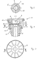
- FIG. 1 shows a cross-sectional view of an embodiment of a valve plug 1, which is provided for screwing into a double-lid of a lead-acid battery.
- a double lid has in a conventional manner an adjacent to the cell compartment lower lid, a delimited with webs cavity and a lid top upper lid.
- the webs extending between the bottom and top covers provide labyrinths through which a gas stream can be directed to a vent and collected in the electrolyte and returned to the cells.
- the illustrated section AA is a cross section through the valve plug. 1
- the valve plug 1 has a valve body 2 made of a first, rigid plastic material, such as polypropylene PP. is formed. On the valve body 2, a valve element 3 made of a second, elastic plastic material is integrally formed.
- the second, elastic plastic material may be, for example, a rubber-elastic material. Suitable are fluoroelastomers, silicone rubber materials or other thermoelastic elastomers.
- valve plug 1 On the valve body 2, an external thread 4 is integrally formed to screw the valve plug 1 in a container opening.
- the valve plug 1 has a profiled cover part 9.
- valve body 2 a plug member 5 is inserted, which is introduced into the valve body 2 after the molding of the valve body 2 and the valve element 2 integrally connected thereto.
- the plug part 5 can be firmly connected to the valve body 2 in the lower region by welding or thermoplastic deformation.
- the valve plug 1 is produced by first molding the valve body 2 by injection molding. Subsequently, the second elastic material is injected by means of a suitable mold into the valve body 2 to form the valve element 3.
- the valve element 3 essentially has a disk-shaped sealing surface section 6, which carries on its side facing the plug part 5 a circumferential annular elevation in the manner of a sealing lip 7.
- the second elastic plastic material is guided outwardly via an injection bore to form a second annular seal 12 for the lower cover at the upper circumference of the valve body 2, a first annular seal 11 and spaced therefrom downwardly adjacent to the thread 4.
- the first ring seal 11 is provided for the upper lid.
- valve-forming sealing surface portion 6 is molded as a flat plate in the interior of the plug together with the ring seals 11, 12, a holding portion 10 and a connecting part 8 in a manufacturing process.
- the resulting valve element 3 also connects all around gas-tight with the wall of the valve body 2 of the plug.
- a circumferential sealing lip 7 is formed. This comes on the inserted from below, serving as a valve holder plug part 5 to the system and is acted upon by the plug part 5 with a pre-pressure, which ensures that the battery can degas on the one hand, but closes the valve at a minimum overpressure before oxygen penetrates.
- the valve function is influenced by an annular or ring-segment-shaped recess 13 located outside the sealing lip 7 in the form of a slot.
- the slot 13 may be different in length, depending on the required valve behavior. It is also conceivable to divide the slot 13 by at least one web.
- the material thickness of the valve 6 can be weakened at the top in the region of the slot 13 by a step to set a finer valve action. Furthermore, it is possible to improve the valve effect to weaken the material thickness outside of the sealing lip 7 by molding from below.
- the proposed type of valve 6 has the advantage that it is easy to manufacture. Existing plug shapes can be adapted with little effort for the production of the valve plug.
- At least one recess 13 is provided in the sealing surface section 6, in the region of which the sealing surface section 6 is open.
- the resilient region is made softer than in the surrounding region of the sealing surface section 6, and thus enables a defined response of the valve function in this area.
- a degassing channel 14 is provided in the valve plug 1, which adjoins a degassing channel in the double cover (not shown).
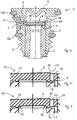
- FIG. 2 lets a sectional view through the sealing surface section 6 recognize. It becomes clear that the sealing surface section 6 has a ring segment-shaped recess 13. Other shapes of the recess 13 are advantageously used.
- the cut BB off FIG. 2 is in the FIG. 1 shown.
- FIG. 3 leaves a top view of the valve plug 1 from FIG. 1 detect.
- section AA of FIG. 1 clear.
- FIG. 4 a further embodiment of the valve plug 1 is shown, in which a after insertion into the valve body 2 obliquely arranged sealing surface portion 6 is provided.
- the corresponding obliquely running at its top sealing surface portion 6 is provided in the highlighted by dashed lines region 15 above the plug part 5.
- the area 15 is in the FIGS. 5 and 6 with reference to two embodiments of the sealing surface portion 6 enlarged as a section shown.
- a sealing surface portion 6 is provided, the material thickness of which increases from the connecting part 8 in the direction of the recess 13 out approximately linearly. As can be seen, the top surface of the sealing surface portion 6 is at a higher level at location 16 than at location 17.
- a sealing surface portion 6 is shown, the material thickness is substantially constant. Instead, the height of the annular sealing lip 7 is different in size over its circumference. As can be seen, the sealing lip 7 in the region 18 in the vicinity of the recess 13 significantly larger than, for example, in the region 20. This also results in a higher level of the surface of the sealing surface portion 6 at the point 16 in comparison to the location 17th
- the sealing surface portion 6 is in the region of the recess 13 and in the region of the point 16 under an increased bias against the surface in contact with the sealing lip 7 of the valve plug 5.
- the increased preload is reflected in the mounted in the valve plug 1 state of the sealing surface portion by the higher level position of the top of the sealing surface portion 6 at the point 16 in comparison to the level at the point 19. In the unmounted state of the sealing surface portion 6, this relaxes. In this case, the point 16 is approximately at the same level as the points 17 and 19.
- degassing proceeds as follows: When a corresponding overpressure is established within the battery or the plug part 5, the sealing surface section 6 is acted upon from below by a force resulting from the overpressure. From a certain overpressure opens the valve function of the sealing surface portion 6, so that the sealing lip 7 in the region of the recess 13 slightly lifts off from the plug part 5 and releases a gas flow channel. The outflowing gas can then escape through the recess 13 and the degassing 14.
Landscapes
- Chemical & Material Sciences (AREA)
- Chemical Kinetics & Catalysis (AREA)
- Electrochemistry (AREA)
- General Chemical & Material Sciences (AREA)
- Engineering & Computer Science (AREA)
- General Engineering & Computer Science (AREA)
- Mechanical Engineering (AREA)
- Gas Exhaust Devices For Batteries (AREA)
- Filling, Topping-Up Batteries (AREA)
- Closures For Containers (AREA)
Description
- Die Erfindung betrifft einen Ventilstopfen zum Abdichten einer Behälteröffnung mit einem auf die Behälteröffnung aufsetzbaren Ventilkörper aus einem ersten, steifen Kunststoffmaterial und einem integral mit dem Ventilkörper verbundenen Ventilelement aus einem zweiten, elastischen Kunststoffmaterial, das elastischer als das erste Kunststoffmaterial ist, wobei das Ventilelement eine auf eine die Behälteröffnung begrenzende Anlagekante aufsetzbaren Dichtflächenabschnitt und ein Verbindungsteil hat, das den Dichtflächenabschnitt in der gewünschten Position hält.
- Derartige Ventilstopfen werden insbesondere zum Verschließen von Füll- und Kontrollöffnungen von Akkumulatoren, insbesondere von Blei-Säure-Batterien für Kraftfahrzeuge genutzt. Mit Hilfe der in den Ventilstopfen eingebauten Ventilelemente soll ein Gasaustritt ermöglicht werden, falls ein Überdruck in dem Batteriegehäuse entsteht.
- Beispielsweise aus
EP 1 194 962 B1 ist bekannt, eine elastische Kappe auf einen Rohrstutzen aufzusetzen, der eine Behälteröffnung einer Batteriezelle begrenzt. Oberhalb der elastischen Kappe ist ein den Batteriedeckel abschließender separater Verschlussdeckel aufgesetzt. Bei einem Überdruck kann Gas durch den Zwischenraum zwischen Rohrstutzen und elastischer Kappe aufgrund der elastischen Verformbarkeit der elastischen Kappe vom Zelleninneren nach Außen gelangen. - Aus der
DE 1 196 258 B ist eine Verschlusskappe aus elastisch nachgiebigem Material für Füllstutzen für Akkumulatorgehäuse bekannt. -
EP 1 001 905 B1 offenbart ein Dichtungsventil aus gummielastischem Material mit einem Stopfenteil, das in eine Behälteröffnung bis zu einem das Stopfenteil in radialer Richtung überragenden Stopfenkragen einführbar ist. An dem Stopfenteil ist mindestens ein Steuerkanal durch eine Ausnehmung im Stopfenteil ausgebildet, der sich von einer Unterseite des Stopfenteils in Richtung der Längsachse des Dichtungsventils bis zum Stopfenkragen erstreckt. An dem Stopfenkragen ist ein Dichtungswulst angeformt, der auf einen die Behälteröffnung umschließenden Behälterrand dichtend auflegbar ist. Zudem wird der Steuerkanal im Stopfenteil bis zum Dichtungswulst fortgeführt. -
DE 103 49 395 B3 zeigt einen Ventilstopfen bei dem ein Ventil aus einem elastischen Material einstückig an einem Grundkörper angeformt ist, so dass das Ventil und der Grundkörper ein Mehrkomponenten- Spritzgussteil bilden. Das als Formteil einstückige elastische Ventil hat einen Ventilkörper und einen daran angeformten Dichtungslappen, der im Querschnitt dünner als der Ventilkörper ausgebildet ist. Der Dichtungslappen ist am unteren Außenrandbereich des Ventilkörpers angeformt und besitzt die Form einer halbkreisförmigen Scheibe, die zum Abdichten an der Innenkante einer Hülse im Ventilkörper anliegt. - Die Druckschrift
WO 2003/057083A2 betrifft einen Ventilstopfen, der geeignet ist, eine Behälteröffnung abzudichten. Der aus diesem Stand der Technik bekannte Ventilstopfen weist einen auf die Behälteröffnung aufsetzbaren Ventilkörper aus einem ersten, steifen Kunststoffmaterial und einen integral mit dem Ventilkörper verbundenen Ventilelement aus einem zweiten, elastischen Kunststoffmaterial auf, wobei das zweite Kunststoffmaterial elastischer als das erste Kunststoffmaterial ist. Das Ventilelement hat einen auf eine Anlegekante dicht aufsetzbaren Dichtflächenabschnitt und ein Verbindungsteil, das sich vom Dichtflächenabschnitt radial durch eine Öffnung im Ventilkörper zu einem am außenumfang des Ventilkörpers gehaltenen Halteabschnitt hin erstreckt. - Ausgehend hiervon ist es Aufgabe der Erfindung, einen verbesserten Ventilstopfen zum Abdichten einer Behälteröffnung zu schaffen, wobei insbesondere das Ansprechen der Ventilfunktion besser definiert einstellbar ist.
- Die Aufgabe wird mit dem Ventilstopfen gemäß Anspruch 1 gelöst.
- Vorteilhaft wird der Dichtflächenabschnitt nicht wie bei bekannten Ventilstopfen durch eine axiale Abstützung angehalten, sondern maßgeblich durch ein sich in radialer Richtung durch die Aussparung des Ventilkörpers erstreckendes Verbin dungsteil. Durch eine Aussparung im Dichtflächenabschnitt wird erreicht, dass der federnde Bereich dort weicher als im übrigen Umfangsbereich des den Dichtflächenabschnitt auf die Anlagekante pressenden Verbindungsteils ist. Damit wird ein definiertes Ansprechen der Ventilfunktion in diesem Bereich ermöglicht. Das definierte Ansprechen wird zudem durch eine Dichtlippe gewährleistet, durch den die Gefahr des Verklebens des Dichtungsflächenabschnitts mit der Anlagekante der Behälteröffnung reduziert wird. Die Aussparung kann vorteilhaft als ringsegmentförmiger Schlitz ausgebildet sein.
- Vorteilhaft ist es, wenn das Verbindungsteil den Dichtflächenabschnitt fest am Ventilkörper hält, so dass der Dichtflächenabschnitt im Bereich des Verbindungsteils nicht oder nur wenig elastisch nachgibt, während durch die definierte Aussparung im Dichtflächenabschnitt die gewünschte Elastizität des Dichtflächenabschnitts sichergestellt wird, wobei die Form der Aussparung den gewünschten Ansprechdruck des Ventilelements wesentlich bestimmt.
- Vorteilhaft ist es, wenn der Dichtflächenabschnitt durch eine Öffnung im Ventilkörper radial nach außen geführt ist und integral mit einer an der Außenseite des Ventilkörpers angeformten Ringdichtung verbunden ist. Damit wird eine einteilige Ausführungsform des Ventilelementes der Ringdichtung erreicht, die bereits aufgrund ihrer Anordnung stabil im Ventilkörper getragen sind. Zudem wird die Fertigung durch die reduzierte Anzahl der Einspritzpunkte für die zwei unterschiedlichen Materialkomponenten vereinfacht.
- Der Ventilstopfen ist vorzugsweise zum Einsatz in eine Füll- und Kontrollöffnung eines Akkumulators, insbesondere einer Bleistarterbatterie ausgestaltet und besitzt hierzu beispielsweise ein an geeigneter Stelle angeordnetes Außengewinde zum Einschrauben des Ventilstopfens in die Füll- und Kontrollöffnung sowie eine oder zwei im Abstand voneinander benachbarte Ringdichtungen.
- Vorteilhaft ist es, wenn der Dichtflächenabschnitt eine in Richtung eines Stopfenteils weisende ringförmige Dichtlippe aufweist.
- Vorteilhaft ist es, wenn die Höhe der Dichtlippe über ihren Umfang variiert, d. h. unterschiedliche Höhen aufweist.
- Vorteilhaft ist es, wenn die Dichtlippe die größte Höhe im Bereich der Aussparung aufweist.
- Vorteilhaft ist es, wenn die Materialdicke des Dichtflächenabschnitts auf der dem Halteabschnitt abgewandten Seite von dem Verbindungsteil fort ansteigt.
- Vorteilhaft ist es, wenn die Materialdicke des Dichtflächenabschnitts linear ansteigt.
- Durch die ungleichmäßige Ausbildung der Höhe der Dichtlippe oder der Materialdicke des Dichtflächenabschnitts wird eine Schräge gebildet. Durch die Schräge entsteht beim Einschieben des Dichtflächenabschnitts in den Ventilstopfen eine größere Vorspannung gegenüber dem darunter liegenden Stopfenteil, dessen zu dem Dichtflächenabschnitt gewandte Oberseite als Ventilsitz dient. Hierdurch kann eine verbesserte Ventilfunktion ermöglicht werden. Es wird dadurch erreicht, dass das Ventil vor einer völligen Entgasung eines Akkumulators rechtzeitig wieder schließt. Vorteilhaft befindet sich die dickste Stelle des Dichtflächenabschnitts bzw. der Dichtlippe im Bereich des zuvor erwähnten ringsegmentförmigen Schlitzes im Dichtflächenabschnitt. Vorteilhaft kann die ungleichmäßige Ausbildung der Höhe der Dichtlippe mit der ungleichmäßigen Ausbildung der Materialdicke kombiniert werden.
- Die Erfindung wird nachfolgend anhand eines Ausführungsbeispiels mit den beigefügten Zeichnungen näher erläutert. Es zeigen:
- Figur 1
- - Querschnittsansicht eines Ventilstopfens zum Einschrauben in einen Doppeldeckel einer Bleibatterie im Schnitt A-A (
Figur 3 ); - Figur 2
- - Draufsicht auf einen Schnitt B-B des elastischen Ventilelementes;
- Figur 3
- - Draufsicht auf den Ventilstopfen aus
Figur 1 ; - Figur 4
- - eine weitere Ausführungsform eines Ventilstopfens; und
- Figur 5
- - eine Detailansicht einer Ausführungsform des Dichtflächenabschnitts; und
- Figur 6
- - eine Detailansicht einer weiteren Ausführungsform des Dichtflächenabschnitts.
- In den Figuren werden gleiche Bezugszeichen für einander entsprechende Elemente verwendet.
-
Figur 1 zeigt eine Querschnittsansicht einer Ausführungsform eines Ventilstopfens 1, der zum Einschrauben in einen Doppeldeckel einer Bleibatterie vorgesehen ist. Ein Doppeldeckel hat in an sich bekannter Weise einen an den Zellenraum angrenzenden Unterdeckel, einen mit Stegen abgegrenzten Hohlraum und einen den Deckel oben abschließenden Oberdeckel. Durch die sich zwischen dem Unter- und Oberdeckel erstreckenden Stege werden Labyrinthe bereitgestellt, durch die ein Gasstrom zu einer Entgasungsöffnung geleitet werden kann und in dem Elektrolyt gesammelt und in die Zellen zurückgeleitet werden kann. - Der dargestellte Schnitt A-A ist ein Querschnitt durch den Ventilstopfen 1.
- Der Ventilstopfen 1 hat einen Ventilkörper 2, der aus einem ersten, steifen Kunststoffmaterial, wie beispielsweise Polypropylen PP. gebildet ist. An dem Ventilkörper 2 ist ein Ventilelement 3 aus einem zweiten, elastischen Kunststoffmaterial integral angeformt. Das zweite, elastische Kunststoffmaterial kann beispielsweise ein gummielastischer Werkstoff sein. Geeignet sind Fluorelastomere, Silikonkautschukmaterialien oder sonstige thermoelastische Elastomere.
- An dem Ventilkörper 2 ist ein Außengewinde 4 angeformt, um den Ventilstopfen 1 in eine Behälteröffnung einzuschrauben. Der Ventilstopfen 1 weist ein profiliertes Deckelteil 9 auf.
- Weiterhin ist in dem Ventilkörper 2 ein Stopfenteil 5 eingesetzt, das nach dem Ausformen des Ventilkörpers 2 und des integral damit verbundenen Ventilelementes 3 in dem Ventilkörper 2 eingeführt wird. Das Stopfenteil 5 kann im unteren Bereich durch Verschweißen oder thermoplastischer Verformung fest mit dem Ventilkörper 2 verbunden werden. Der Ventilstopfen 1 wird hergestellt, indem zunächst der Ventilkörper 2 im Spritzgussverfahren ausgeformt wird. Anschließend wird das zweite elastische Material mit Hilfe einer geeigneten Form in den Ventilkörper 2 eingespritzt, um das Ventilelement 3 zu bilden. Das Ventilelement 3 hat im Wesentlichen einen scheibenförmigen Dichtflächenabschnitt 6, der an seiner dem Stopfenteil 5 zugewandten Seite eine umlaufende ringförmige Erhebung in der Art einer Dichtlippe 7 trägt.
- Das zweite, elastische Kunststoffmaterial wird nach außen über eine Einspritzbohrung geführt, um am oberen Umfang des Ventilkörpers 2 eine erste Ringdichtung 11 und im Abstand davon nach unten angrenzend an das Gewinde 4 eine zweite Ringdichtung 12 für den Unterdeckel zu bilden. Die erste Ringdichtung 11 ist für den Oberdeckel vorgesehen.
- Der ein Ventil bildende Dichtflächenabschnitt 6 wird als flache Platte im Innenraum des Stopfens zusammen mit den Ringdichtungen 11, 12, einem Halteabschnitt 10 und ein Verbindungsteil 8 in einem Fertigungsvorgang angespritzt. Das hierbei entstehende Ventilelement 3 verbindet sich auch ringsum gasdicht mit der Wand des Ventilkörpers 2 des Stopfens. An der Unterseite der Platte 6 ist eine umlaufende Dichtlippe 7 angeformt. Diese kommt auf dem von unten eingeschobenen, als Ventilhalter dienenden Stopfenteil 5 zur Anlage und wird von dem Stopfenteil 5 mit einem Vordruck beaufschlagt, der gewährleistet, dass die Batterie einerseits entgasen kann, aber das Ventil bei einem minimalen Überdruck schließt bevor Sauerstoff eindringt.
- Die Ventilfunktion wird durch eine ringförmige bzw. ringsegmentförmige, außerhalb der Dichtlippe 7 liegende Aussparung 13 in Form eines Schlitzes beeinflusst. Durch den Schlitz 13 wird an dieser Stelle die Steifigkeit des Dichtflächenabschnitts 6 geschwächt, so dass dieser Teil des Ventils bei definierten Drücken öffnet und schließt. Der Schlitz 13 kann unterschiedlich lang sein, je nach erforderlichem Ventilverhalten. Auch ist denkbar, den Schlitz 13 durch wenigstens einen Steg zu teilen.
- Zusätzlich ist es möglich, oberhalb des Ventils 6 eine Stützrippe zur Stabilisierung vorzusehen. Außerdem kann die Materialdicke des Ventils 6 an der Oberseite im Bereich des Schlitzes 13 durch eine Stufe geschwächt werden, um eine feinere Ventilwirkung einzustellen. Weiterhin ist es möglich, zur Verbesserung der Ventilwirkung die Materialdicke außerhalb der Dichtlippe 7 durch Einformung von unten zu schwächen.
- Die vorgeschlagene Art des Ventils 6 hat den Vorteil, dass es einfach zu fertigen ist. Vorhandene Stopfenformen können mit wenig Aufwand für die Produktion des Ventilstopfens angepasst werden.
- Wie erwähnt, ist in dem Dichtflächenabschnitt 6 mindestens eine Aussparung 13 vorgesehen, in deren Bereich der Dichtflächenabschnitt 6 offen ist. Durch die Aussparung 13 wird der federnde Bereich weicher ausgestaltet, als im umliegenden Bereich des Dichtflächenabschnitts 6, und um so ein definiertes Ansprechen der Ventilfunktion in diesem Bereich ermöglicht. Im Bereich der Aussparung 13 ist ein Entgasungskanal 14 im Ventilstopfen 1 vorgesehen, der an einen Entgasungskanal im Doppeldeckel (nicht dargestellt) angrenzt.
-
Figur 2 lässt eine Schnittansicht durch den Dichtflächenabschnitt 6 erkennen. Es wird deutlich, dass der Dichtflächenabschnitt 6 eine ringsegmentförmige Aussparung 13 hat. Auch andere Formen der Aussparung 13 sind vorteilhaft einsetzbar. - Der Schnitt B-B aus
Figur 2 ist in derFigur 1 dargestellt. -
Figur 3 lässt eine Draufsicht auf den Ventilstopfen 1 ausFigur 1 erkennen. Dabei wird der Schnitt A-A derFigur 1 deutlich. - In der
Figur 4 ist eine weitere Ausführungsform des Ventilstopfens 1 dargestellt, bei der ein nach Einsetzen in den Ventilkörper 2 schräg angeordneter Dichtflächenabschnitt 6 vorgesehen ist. Der entsprechend schräg an seiner Oberseite verlaufende Dichtflächenabschnitt 6 ist in dem durch gestrichelte Linien hervorgehobenen Bereich 15 oberhalb des Stopfenteils 5 vorgesehen. Der Bereich 15 ist in denFiguren 5 und 6 anhand zweier Ausführungsformen des Dichtflächenabschnitts 6 vergrößert als Ausschnitt dargestellt. - Gemäß
Figur 5 ist ein Dichtflächenabschnitt 6 vorgesehen, dessen Materialdicke sich von dem Verbindungsteil 8 fort in Richtung zu der Aussparung 13 hin etwa linear vergrößert. Wie erkennbar ist, liegt die Oberseite des Dichtflächenabschnitts 6 an der Stelle 16 auf einem höheren Niveau als an der Stelle 17. - Gemäß
Figur 6 ist ein Dichtflächenabschnitt 6 dargestellt, dessen Materialdicke im Wesentlichen gleich bleibend ist. Statt dessen ist die Höhe der ringförmigen Dichtlippe 7 über deren Umfang unterschiedlich groß. Wie erkennbar ist, ist die Dichtlippe 7 im Bereich 18 in der Nähe der Aussparung 13 deutlich größer als z.B. in dem Bereich 20. Auch hierdurch ergibt sich ein höheres Niveau der Oberfläche des Dichtflächenabschnitts 6 an der Stelle 16 im Vergleich zur Stelle 17. - Den Ausführungsformen gemäß den
Figuren 4 bis 6 gemeinsam ist, dass der Dichtflächenabschnitt 6 im Bereich der Aussparung 13 bzw. im Bereich der Stelle 16 unter einer vergrößerten Vorspannung gegenüber der mit der Dichtlippe 7 in Kontakt stehenden Oberfläche des Ventilstopfens 5 steht. Die erhöhte Vorspannung zeigt sich im in dem Ventilstopfen 1 montierten Zustand des Dichtflächenabschnitts durch die höhere Niveaulage der Oberseite des Dichtflächenabschnitts 6 an der Stelle 16 im Vergleich zu dem Niveau an der Stelle 19. Im unmontierten Zustand des Dichtflächenabschnitts 6 entspannt sich dieser. Hierbei liegt die Stelle 16 etwa auf dem gleichen Niveau wie die Stellen 17 und 19. - Ein Entgasen verläuft bei dem erfindungsgemäßen Ventilstopfen wie folgt: Bei Aufbau eines entsprechenden Überdrucks innerhalb der Batterie bzw. des Stopfenteils 5 wird der Dichtflächenabschnitt 6 von unten mit einer sich aus dem Überdruck ergebenden Kraft beaufschlagt. Ab einem gewissen Überdruck öffnet die Ventilfunktion des Dichtflächenabschnitts 6, so dass die Dichtlippe 7 im Bereich der Aussparung 13 geringfügig von dem Stopfenteil 5 abhebt und einen Gas-Strömungskanal freigibt. Das ausströmende Gas kann dann durch die Aussparung 13 sowie den Entgasungskanal 14 austreten.
Claims (9)
- Ventilstopfen (1) zum Abdichten einer Behälteröffnung mit einem auf die Behälteröffnung aufsetzbaren Ventilkörper (2) aus einem ersten, steifen Kunststoffmaterial und einem integral mit dem Ventilkörper (2) verbundenen Ventilelement (3) aus einem zweiten, elastischen Kunststoffmaterial, das elastischer als das erste Kunststoffmaterial ist, wobei das Ventilelement (3) einen auf eine Anlagekante dicht aufsetzbaren Dichtflächenabschnitt (6) und ein Verbindungsteil (8) hat, das sich vom Dichtflächenabschnitt (6) radial durch eine Öffnung im Ventilkörper (2) zu einem am Außenumfang des Ventilkörpers gehaltenen Halteabschnitt (10) hin erstreckt, dadurch gekennzeichnet, dass der Dichtflächenabschnitt (6) ohne axiale Abstützung des Dichtflächenabschnitt (6) von dem Verbindungsteil (8) gehalten ist, wobei in dem Dichtflächenabschnitt (6) mindestens eine Aussparung (13) in Form eines Schlitzes vorgesehen ist, in deren Bereich der Dichtflächenabschnitt (6) offen ist.
- Ventilstopfen (1) nach Anspruch 1,
wobei die Aussparung (13) ringsegmentförmig ist. - Ventilstopfen (1) nach Anspruch 1 oder 2,
wobei der Halteabschnitt (10) integral mit mindestens einer an der Außenseite des Ventilkörpers angeformten Ringdichtung (11, 12) verbunden ist. - Ventilstopfen (1) nach einem der Ansprüche 1 bis 3,
wobei der Ventilstopfen (1) zum Einsatz in eine Füll- und Kontrollöffnung eines Akkumulators, insbesondere einer Bleibatterie ausgestaltet ist. - Ventilstopfen (1) nach einem der Ansprüche 1 bis 4,
wobei der Dichtflächenabschnitt (6) eine in Richtung eines Stopfenteils (5) weisende ringförmige Dichtlippe (7) aufweist. - Ventilstopfen (1) nach Anspruch 5,
wobei die Höhe der Dichtlippe (7) über ihren Umfang variiert. - Ventilstopfen (1) nach Anspruch 6,
wobei die Dichtlippe (7) die größte Höhe im Bereich der Aussparung (13) aufweist. - Ventilstopfen (1) nach einem der Ansprüche 1 bis 7,
wobei die Materialdicke des Dichtflächenabschnitts (6) auf der dem Halteabschnitt (10) abgewandten Seite von dem Verbindungsteil (8) fort ansteigt. - Ventilstopfen (1) nach Anspruch 8,
wobei die Materialdicke des Dichtflächenabschnitts (6) linear ansteigt.
Applications Claiming Priority (2)
| Application Number | Priority Date | Filing Date | Title |
|---|---|---|---|
| DE102009019346 | 2009-04-30 | ||
| PCT/DE2010/000497 WO2010124684A2 (de) | 2009-04-30 | 2010-04-30 | Ventilstopfen |
Publications (2)
| Publication Number | Publication Date |
|---|---|
| EP2425474A2 EP2425474A2 (de) | 2012-03-07 |
| EP2425474B1 true EP2425474B1 (de) | 2017-12-13 |
Family
ID=42953817
Family Applications (1)
| Application Number | Title | Priority Date | Filing Date |
|---|---|---|---|
| EP10725002.9A Active EP2425474B1 (de) | 2009-04-30 | 2010-04-30 | Ventilstopfen |
Country Status (4)
| Country | Link |
|---|---|
| US (1) | US8608005B2 (de) |
| EP (1) | EP2425474B1 (de) |
| CN (1) | CN102439759B (de) |
| WO (1) | WO2010124684A2 (de) |
Families Citing this family (12)
| Publication number | Priority date | Publication date | Assignee | Title |
|---|---|---|---|---|
| KR101252631B1 (ko) * | 2010-11-08 | 2013-04-09 | 세방전지(주) | 자동차용 배터리 및 극판 제조방법 |
| DE102012111409B4 (de) * | 2012-11-26 | 2018-12-20 | Johnson Controls Autobatterie Gmbh & Co. Kgaa | Anschlusspol für einen Akkumulator und Akkumulator |
| DE102013105511A1 (de) | 2013-05-29 | 2014-12-18 | Johnson Controls Autobatterie Gmbh & Co. Kgaa | Verschlussstopfenanordnung, Gehäuse und Akkumulator |
| DE102013105817A1 (de) | 2013-06-06 | 2014-12-11 | Johnson Controls Autobatterie Gmbh & Co. Kgaa | Verschlussstopfenanordnung, Gehäuse eines Akkumulators und Akkumulator |
| JP6222573B2 (ja) * | 2014-10-10 | 2017-11-01 | Smc株式会社 | パイロットチェック弁 |
| US9693842B2 (en) * | 2015-10-28 | 2017-07-04 | Stoma Ventures, LLC | Disposable dental valve device having a check valve |
| US10010712B2 (en) * | 2015-10-28 | 2018-07-03 | Stoma Ventures, LLC | Disposable dental valve device having a check valve |
| CN107359304B (zh) * | 2016-05-10 | 2020-08-28 | 宁德时代新能源科技股份有限公司 | 锂离子电池注液孔密封结构 |
| DE102017100049A1 (de) * | 2017-01-03 | 2018-07-05 | Johnson Controls Autobatterie Gmbh & Co. Kgaa | Stopfen zum verschliessen und abdichten einer öffnung in einem gehäuse eines energiespeichersystems und energiespeichersystem |
| JP7034614B2 (ja) * | 2017-06-30 | 2022-03-14 | ピジョン株式会社 | 逆流防止弁 |
| DE102018211471B3 (de) * | 2018-07-11 | 2019-09-05 | Audi Ag | Batteriegehäuse |
| EP4465438A1 (de) * | 2023-05-18 | 2024-11-20 | Sovema Group S.P.A. | Kappe für elektrolytzellen und verfahren zur herstellung einer elektrolytzelle |
Citations (2)
| Publication number | Priority date | Publication date | Assignee | Title |
|---|---|---|---|---|
| EP0601491A1 (de) * | 1992-12-11 | 1994-06-15 | Busak + Shamban GmbH & Co. | Verschlussmittel und Dichtungsventil für Behälteröffnungen |
| WO2003057083A2 (en) * | 2001-12-28 | 2003-07-17 | Helix Medical, Inc. | Valve mounting assembly for voice prosthesis-cartridge and ring |
Family Cites Families (7)
| Publication number | Priority date | Publication date | Assignee | Title |
|---|---|---|---|---|
| US2971045A (en) | 1958-07-07 | 1961-02-07 | Sonotone Corp | Gas vent closure for electric storage batteries |
| SU1023460A1 (ru) | 1978-05-16 | 1983-06-15 | Предприятие П/Я В-2410 | Вентил ционно-защитное устройство электрического аккумул тора |
| DE29714031U1 (de) | 1997-08-06 | 1997-10-23 | Busak + Shamban GmbH & Co, 70565 Stuttgart | Dichtungsventil |
| IT1315319B1 (it) | 2000-04-20 | 2003-02-10 | Franco Stocchiero | Gruppo valvolare di tenuta e di sfiato per accumulatori elettrici |
| ITVI20010240A1 (it) * | 2001-11-14 | 2003-05-14 | Franco Stocchiero | Gruppo valvolare di tenuta e di sfiato per accumulatori elettrici |
| DE10349395B3 (de) * | 2003-10-21 | 2005-01-05 | Hartung Kunststoffwerk-Werkzeugbau Gmbh | Vorrichtung zum Abdichten einer Behälteröffnung |
| US20070166606A1 (en) | 2006-01-17 | 2007-07-19 | Brecht William B | Hinged battery vent cap and related ganged vent assembly |
-
2010
- 2010-04-30 WO PCT/DE2010/000497 patent/WO2010124684A2/de not_active Ceased
- 2010-04-30 US US13/318,034 patent/US8608005B2/en active Active
- 2010-04-30 CN CN201080018781.7A patent/CN102439759B/zh active Active
- 2010-04-30 EP EP10725002.9A patent/EP2425474B1/de active Active
Patent Citations (2)
| Publication number | Priority date | Publication date | Assignee | Title |
|---|---|---|---|---|
| EP0601491A1 (de) * | 1992-12-11 | 1994-06-15 | Busak + Shamban GmbH & Co. | Verschlussmittel und Dichtungsventil für Behälteröffnungen |
| WO2003057083A2 (en) * | 2001-12-28 | 2003-07-17 | Helix Medical, Inc. | Valve mounting assembly for voice prosthesis-cartridge and ring |
Also Published As
| Publication number | Publication date |
|---|---|
| WO2010124684A3 (de) | 2010-12-23 |
| EP2425474A2 (de) | 2012-03-07 |
| WO2010124684A2 (de) | 2010-11-04 |
| CN102439759B (zh) | 2015-07-29 |
| US20120085762A1 (en) | 2012-04-12 |
| US8608005B2 (en) | 2013-12-17 |
| CN102439759A (zh) | 2012-05-02 |
Similar Documents
| Publication | Publication Date | Title |
|---|---|---|
| EP2425474B1 (de) | Ventilstopfen | |
| EP1207969B2 (de) | Entlüftungsvorrichtung bei einem kolben für eine kartusche | |
| DE10205344B4 (de) | Hermetisch verschlossener Behälter mit durchstechbarem Zugangseinlass | |
| EP2539245B1 (de) | Verpackung | |
| DE102011080325A1 (de) | Druckausgleichsvorrichtung für ein Gehäuse einer elektrochemischen Vorrichtung | |
| DE29714031U1 (de) | Dichtungsventil | |
| EP2225786B1 (de) | Ventilstopfen | |
| WO2016030419A1 (de) | Filter, der an einen anschlussflansch anbaubar ist, und filtereinsatz | |
| EP2028131A2 (de) | Feststoffventil | |
| CH665502A5 (de) | Galvanisches primaerelement. | |
| EP3005445B1 (de) | Verschlussstopfenanordnung, gehäuse und akkumulator | |
| EP2478577B1 (de) | Verschlussstopfenanordnung für einen akkumulator | |
| DE102021106903A1 (de) | Druckausgleichsvorrichtung | |
| EP3539172A1 (de) | Druckentlastungsdeckel zum abbau von in einem zellenartigen hohlraum, wie einer batteriezelle, entstehendem druck | |
| DE102008001594A1 (de) | Träger mit Druckausgleichsmembran sowie Antriebsvorrichtung, insbesondere für Kraftfahrzeuganwendungen | |
| WO2021190791A1 (de) | Batterieschale, traktionsbatterie, kraftfahrzeug und verfahren zum herstellen einer batterieschale | |
| EP3253677B1 (de) | Leitungsabschlusselement für einen ventilationsabgang eines fluidbehälters sowie fluidbehälter | |
| EP2842714B1 (de) | Druckausgleichselement | |
| EP2840285B1 (de) | Belüftungsventil für einen Flüssigkeitsbehälter | |
| DE102010029796A1 (de) | Wasserablaufventil für Elektronikgehäuse und Elektronikgehäuse mit einem solchen Wasserablaufventil | |
| EP3005446B1 (de) | Verschlussstopfenanordnung, gehäuse eines akkumulators und akkumulator | |
| EP3566254B1 (de) | Stopfen zum verschliessen und abdichten einer öffnung in einem gehäuse eines energiespeichersystems und energiespeichersystem | |
| WO2007068011A1 (de) | Universelle verschlussvorrichtung | |
| DE9107094U1 (de) | Dichtungsventil für Behälteröffnungen | |
| EP2337718B1 (de) | Pneumatisches belüftungsventil |
Legal Events
| Date | Code | Title | Description |
|---|---|---|---|
| PUAI | Public reference made under article 153(3) epc to a published international application that has entered the european phase |
Free format text: ORIGINAL CODE: 0009012 |
|
| 17P | Request for examination filed |
Effective date: 20111010 |
|
| AK | Designated contracting states |
Kind code of ref document: A2 Designated state(s): AT BE BG CH CY CZ DE DK EE ES FI FR GB GR HR HU IE IS IT LI LT LU LV MC MK MT NL NO PL PT RO SE SI SK SM TR |
|
| DAX | Request for extension of the european patent (deleted) | ||
| 17Q | First examination report despatched |
Effective date: 20130528 |
|
| RAP1 | Party data changed (applicant data changed or rights of an application transferred) |
Owner name: JOHNSON CONTROLS AUTOBATTERIE GMBH & CO. KGAA |
|
| GRAP | Despatch of communication of intention to grant a patent |
Free format text: ORIGINAL CODE: EPIDOSNIGR1 |
|
| STAA | Information on the status of an ep patent application or granted ep patent |
Free format text: STATUS: GRANT OF PATENT IS INTENDED |
|
| RIC1 | Information provided on ipc code assigned before grant |
Ipc: H01M 10/06 20060101ALI20170530BHEP Ipc: H01M 2/12 20060101AFI20170530BHEP Ipc: F16K 15/14 20060101ALI20170530BHEP Ipc: H01M 2/36 20060101ALI20170530BHEP |
|
| INTG | Intention to grant announced |
Effective date: 20170626 |
|
| GRAS | Grant fee paid |
Free format text: ORIGINAL CODE: EPIDOSNIGR3 |
|
| GRAA | (expected) grant |
Free format text: ORIGINAL CODE: 0009210 |
|
| STAA | Information on the status of an ep patent application or granted ep patent |
Free format text: STATUS: THE PATENT HAS BEEN GRANTED |
|
| AK | Designated contracting states |
Kind code of ref document: B1 Designated state(s): AT BE BG CH CY CZ DE DK EE ES FI FR GB GR HR HU IE IS IT LI LT LU LV MC MK MT NL NO PL PT RO SE SI SK SM TR |
|
| REG | Reference to a national code |
Ref country code: GB Ref legal event code: FG4D Free format text: NOT ENGLISH |
|
| REG | Reference to a national code |
Ref country code: AT Ref legal event code: REF Ref document number: 955175 Country of ref document: AT Kind code of ref document: T Effective date: 20171215 Ref country code: CH Ref legal event code: EP |
|
| REG | Reference to a national code |
Ref country code: IE Ref legal event code: FG4D Free format text: LANGUAGE OF EP DOCUMENT: GERMAN |
|
| REG | Reference to a national code |
Ref country code: DE Ref legal event code: R096 Ref document number: 502010014470 Country of ref document: DE |
|
| REG | Reference to a national code |
Ref country code: NL Ref legal event code: MP Effective date: 20171213 |
|
| REG | Reference to a national code |
Ref country code: LT Ref legal event code: MG4D Ref country code: FR Ref legal event code: PLFP Year of fee payment: 9 |
|
| PG25 | Lapsed in a contracting state [announced via postgrant information from national office to epo] |
Ref country code: SE Free format text: LAPSE BECAUSE OF FAILURE TO SUBMIT A TRANSLATION OF THE DESCRIPTION OR TO PAY THE FEE WITHIN THE PRESCRIBED TIME-LIMIT Effective date: 20171213 Ref country code: FI Free format text: LAPSE BECAUSE OF FAILURE TO SUBMIT A TRANSLATION OF THE DESCRIPTION OR TO PAY THE FEE WITHIN THE PRESCRIBED TIME-LIMIT Effective date: 20171213 Ref country code: NO Free format text: LAPSE BECAUSE OF FAILURE TO SUBMIT A TRANSLATION OF THE DESCRIPTION OR TO PAY THE FEE WITHIN THE PRESCRIBED TIME-LIMIT Effective date: 20180313 Ref country code: LT Free format text: LAPSE BECAUSE OF FAILURE TO SUBMIT A TRANSLATION OF THE DESCRIPTION OR TO PAY THE FEE WITHIN THE PRESCRIBED TIME-LIMIT Effective date: 20171213 |
|
| PG25 | Lapsed in a contracting state [announced via postgrant information from national office to epo] |
Ref country code: HR Free format text: LAPSE BECAUSE OF FAILURE TO SUBMIT A TRANSLATION OF THE DESCRIPTION OR TO PAY THE FEE WITHIN THE PRESCRIBED TIME-LIMIT Effective date: 20171213 Ref country code: LV Free format text: LAPSE BECAUSE OF FAILURE TO SUBMIT A TRANSLATION OF THE DESCRIPTION OR TO PAY THE FEE WITHIN THE PRESCRIBED TIME-LIMIT Effective date: 20171213 Ref country code: GR Free format text: LAPSE BECAUSE OF FAILURE TO SUBMIT A TRANSLATION OF THE DESCRIPTION OR TO PAY THE FEE WITHIN THE PRESCRIBED TIME-LIMIT Effective date: 20180314 Ref country code: BG Free format text: LAPSE BECAUSE OF FAILURE TO SUBMIT A TRANSLATION OF THE DESCRIPTION OR TO PAY THE FEE WITHIN THE PRESCRIBED TIME-LIMIT Effective date: 20180313 |
|
| PG25 | Lapsed in a contracting state [announced via postgrant information from national office to epo] |
Ref country code: NL Free format text: LAPSE BECAUSE OF FAILURE TO SUBMIT A TRANSLATION OF THE DESCRIPTION OR TO PAY THE FEE WITHIN THE PRESCRIBED TIME-LIMIT Effective date: 20171213 |
|
| PG25 | Lapsed in a contracting state [announced via postgrant information from national office to epo] |
Ref country code: CY Free format text: LAPSE BECAUSE OF FAILURE TO SUBMIT A TRANSLATION OF THE DESCRIPTION OR TO PAY THE FEE WITHIN THE PRESCRIBED TIME-LIMIT Effective date: 20171213 Ref country code: EE Free format text: LAPSE BECAUSE OF FAILURE TO SUBMIT A TRANSLATION OF THE DESCRIPTION OR TO PAY THE FEE WITHIN THE PRESCRIBED TIME-LIMIT Effective date: 20171213 Ref country code: SK Free format text: LAPSE BECAUSE OF FAILURE TO SUBMIT A TRANSLATION OF THE DESCRIPTION OR TO PAY THE FEE WITHIN THE PRESCRIBED TIME-LIMIT Effective date: 20171213 Ref country code: CZ Free format text: LAPSE BECAUSE OF FAILURE TO SUBMIT A TRANSLATION OF THE DESCRIPTION OR TO PAY THE FEE WITHIN THE PRESCRIBED TIME-LIMIT Effective date: 20171213 Ref country code: ES Free format text: LAPSE BECAUSE OF FAILURE TO SUBMIT A TRANSLATION OF THE DESCRIPTION OR TO PAY THE FEE WITHIN THE PRESCRIBED TIME-LIMIT Effective date: 20171213 |
|
| PG25 | Lapsed in a contracting state [announced via postgrant information from national office to epo] |
Ref country code: IS Free format text: LAPSE BECAUSE OF FAILURE TO SUBMIT A TRANSLATION OF THE DESCRIPTION OR TO PAY THE FEE WITHIN THE PRESCRIBED TIME-LIMIT Effective date: 20180413 Ref country code: SM Free format text: LAPSE BECAUSE OF FAILURE TO SUBMIT A TRANSLATION OF THE DESCRIPTION OR TO PAY THE FEE WITHIN THE PRESCRIBED TIME-LIMIT Effective date: 20171213 Ref country code: RO Free format text: LAPSE BECAUSE OF FAILURE TO SUBMIT A TRANSLATION OF THE DESCRIPTION OR TO PAY THE FEE WITHIN THE PRESCRIBED TIME-LIMIT Effective date: 20171213 Ref country code: PL Free format text: LAPSE BECAUSE OF FAILURE TO SUBMIT A TRANSLATION OF THE DESCRIPTION OR TO PAY THE FEE WITHIN THE PRESCRIBED TIME-LIMIT Effective date: 20171213 |
|
| REG | Reference to a national code |
Ref country code: DE Ref legal event code: R097 Ref document number: 502010014470 Country of ref document: DE |
|
| PG25 | Lapsed in a contracting state [announced via postgrant information from national office to epo] |
Ref country code: MT Free format text: LAPSE BECAUSE OF FAILURE TO SUBMIT A TRANSLATION OF THE DESCRIPTION OR TO PAY THE FEE WITHIN THE PRESCRIBED TIME-LIMIT Effective date: 20171213 |
|
| PLBE | No opposition filed within time limit |
Free format text: ORIGINAL CODE: 0009261 |
|
| STAA | Information on the status of an ep patent application or granted ep patent |
Free format text: STATUS: NO OPPOSITION FILED WITHIN TIME LIMIT |
|
| 26N | No opposition filed |
Effective date: 20180914 |
|
| PG25 | Lapsed in a contracting state [announced via postgrant information from national office to epo] |
Ref country code: DK Free format text: LAPSE BECAUSE OF FAILURE TO SUBMIT A TRANSLATION OF THE DESCRIPTION OR TO PAY THE FEE WITHIN THE PRESCRIBED TIME-LIMIT Effective date: 20171213 Ref country code: MC Free format text: LAPSE BECAUSE OF FAILURE TO SUBMIT A TRANSLATION OF THE DESCRIPTION OR TO PAY THE FEE WITHIN THE PRESCRIBED TIME-LIMIT Effective date: 20171213 |
|
| REG | Reference to a national code |
Ref country code: CH Ref legal event code: PL |
|
| REG | Reference to a national code |
Ref country code: BE Ref legal event code: MM Effective date: 20180430 |
|
| REG | Reference to a national code |
Ref country code: IE Ref legal event code: MM4A |
|
| PG25 | Lapsed in a contracting state [announced via postgrant information from national office to epo] |
Ref country code: LU Free format text: LAPSE BECAUSE OF NON-PAYMENT OF DUE FEES Effective date: 20180430 |
|
| PG25 | Lapsed in a contracting state [announced via postgrant information from national office to epo] |
Ref country code: LI Free format text: LAPSE BECAUSE OF NON-PAYMENT OF DUE FEES Effective date: 20180430 Ref country code: SI Free format text: LAPSE BECAUSE OF FAILURE TO SUBMIT A TRANSLATION OF THE DESCRIPTION OR TO PAY THE FEE WITHIN THE PRESCRIBED TIME-LIMIT Effective date: 20171213 Ref country code: BE Free format text: LAPSE BECAUSE OF NON-PAYMENT OF DUE FEES Effective date: 20180430 Ref country code: CH Free format text: LAPSE BECAUSE OF NON-PAYMENT OF DUE FEES Effective date: 20180430 |
|
| PG25 | Lapsed in a contracting state [announced via postgrant information from national office to epo] |
Ref country code: IE Free format text: LAPSE BECAUSE OF NON-PAYMENT OF DUE FEES Effective date: 20180430 |
|
| REG | Reference to a national code |
Ref country code: AT Ref legal event code: MM01 Ref document number: 955175 Country of ref document: AT Kind code of ref document: T Effective date: 20180430 |
|
| REG | Reference to a national code |
Ref country code: DE Ref legal event code: R082 Ref document number: 502010014470 Country of ref document: DE Representative=s name: MEISSNER BOLTE PATENTANWAELTE RECHTSANWAELTE P, DE |
|
| PG25 | Lapsed in a contracting state [announced via postgrant information from national office to epo] |
Ref country code: AT Free format text: LAPSE BECAUSE OF NON-PAYMENT OF DUE FEES Effective date: 20180430 |
|
| PG25 | Lapsed in a contracting state [announced via postgrant information from national office to epo] |
Ref country code: TR Free format text: LAPSE BECAUSE OF FAILURE TO SUBMIT A TRANSLATION OF THE DESCRIPTION OR TO PAY THE FEE WITHIN THE PRESCRIBED TIME-LIMIT Effective date: 20171213 |
|
| PG25 | Lapsed in a contracting state [announced via postgrant information from national office to epo] |
Ref country code: HU Free format text: LAPSE BECAUSE OF FAILURE TO SUBMIT A TRANSLATION OF THE DESCRIPTION OR TO PAY THE FEE WITHIN THE PRESCRIBED TIME-LIMIT; INVALID AB INITIO Effective date: 20100430 Ref country code: PT Free format text: LAPSE BECAUSE OF FAILURE TO SUBMIT A TRANSLATION OF THE DESCRIPTION OR TO PAY THE FEE WITHIN THE PRESCRIBED TIME-LIMIT Effective date: 20171213 |
|
| PG25 | Lapsed in a contracting state [announced via postgrant information from national office to epo] |
Ref country code: MK Free format text: LAPSE BECAUSE OF NON-PAYMENT OF DUE FEES Effective date: 20171213 |
|
| REG | Reference to a national code |
Ref country code: DE Ref legal event code: R079 Ref document number: 502010014470 Country of ref document: DE Free format text: PREVIOUS MAIN CLASS: H01M0002120000 Ipc: H01M0050300000 |
|
| REG | Reference to a national code |
Ref country code: DE Ref legal event code: R082 Ref document number: 502010014470 Country of ref document: DE Representative=s name: MEISSNER BOLTE PATENTANWAELTE RECHTSANWAELTE P, DE Ref country code: DE Ref legal event code: R081 Ref document number: 502010014470 Country of ref document: DE Owner name: CLARIOS GERMANY GMBH & CO. KGAA, DE Free format text: FORMER OWNER: JOHNSON CONTROLS AUTOBATTERIE GMBH & CO. KGAA, 30419 HANNOVER, DE |
|
| P01 | Opt-out of the competence of the unified patent court (upc) registered |
Free format text: CASE NUMBER: APP_865/2025 Effective date: 20250108 |
|
| PGFP | Annual fee paid to national office [announced via postgrant information from national office to epo] |
Ref country code: DE Payment date: 20250429 Year of fee payment: 16 |
|
| PGFP | Annual fee paid to national office [announced via postgrant information from national office to epo] |
Ref country code: GB Payment date: 20250428 Year of fee payment: 16 |
|
| PGFP | Annual fee paid to national office [announced via postgrant information from national office to epo] |
Ref country code: IT Payment date: 20250422 Year of fee payment: 16 |
|
| PGFP | Annual fee paid to national office [announced via postgrant information from national office to epo] |
Ref country code: FR Payment date: 20250425 Year of fee payment: 16 |