EP2425305B1 - Erzeugung von regelungsparametern mit stabilitätsüberwachung - Google Patents
Erzeugung von regelungsparametern mit stabilitätsüberwachung Download PDFInfo
- Publication number
- EP2425305B1 EP2425305B1 EP10731621.8A EP10731621A EP2425305B1 EP 2425305 B1 EP2425305 B1 EP 2425305B1 EP 10731621 A EP10731621 A EP 10731621A EP 2425305 B1 EP2425305 B1 EP 2425305B1
- Authority
- EP
- European Patent Office
- Prior art keywords
- signal
- control system
- waveform
- test
- parameters
- Prior art date
- Legal status (The legal status is an assumption and is not a legal conclusion. Google has not performed a legal analysis and makes no representation as to the accuracy of the status listed.)
- Active
Links
Images
Classifications
-
- G—PHYSICS
- G05—CONTROLLING; REGULATING
- G05B—CONTROL OR REGULATING SYSTEMS IN GENERAL; FUNCTIONAL ELEMENTS OF SUCH SYSTEMS; MONITORING OR TESTING ARRANGEMENTS FOR SUCH SYSTEMS OR ELEMENTS
- G05B13/00—Adaptive control systems, i.e. systems automatically adjusting themselves to have a performance which is optimum according to some preassigned criterion
- G05B13/02—Adaptive control systems, i.e. systems automatically adjusting themselves to have a performance which is optimum according to some preassigned criterion electric
- G05B13/0205—Adaptive control systems, i.e. systems automatically adjusting themselves to have a performance which is optimum according to some preassigned criterion electric not using a model or a simulator of the controlled system
- G05B13/024—Adaptive control systems, i.e. systems automatically adjusting themselves to have a performance which is optimum according to some preassigned criterion electric not using a model or a simulator of the controlled system in which a parameter or coefficient is automatically adjusted to optimise the performance
- G05B13/025—Adaptive control systems, i.e. systems automatically adjusting themselves to have a performance which is optimum according to some preassigned criterion electric not using a model or a simulator of the controlled system in which a parameter or coefficient is automatically adjusted to optimise the performance using a perturbation signal
Definitions
- This disclosure relates to generally to electro-magnetic material test systems.
- the present invention relates to feedback controller parameter generation and initial controller stability monitoring.
- US5623402 discloses multi-channel inverse control using adaptive finite impulse response filters. Servo Controller Compensation Methods Selection of the Correct Technique for Test Applications (XP002600811), 1999-01-3000, Society of Automotive engineers, discloses iterative deconvolution compensation. US5517426 discloses an apparatus and method for adaptive closed loop control of shock testing system.
- the present invention provides a method of confirming stability of a control system (400) for a materials testing system the method comprising: determining specified filter parameters (406, 408, 410) for the control system (400) by:
- the stability test signal includes two square waves centered at the mean position of the command signal. The square waves have a frequency of 1 Hz.
- the stability test signal includes a waveform matching a waveform of the command signal and having an amplitude of 95 percent of the command signal's amplitude.
- the threshold varies with the stability test signal. The threshold is a percentage of the stability test signal amplitude.
- the stability test signal includes a combination of a low-frequency and slightly attenuated version of the command signal and a small-amplitude, high-frequency signal. Taking the first action includes stopping operation of the control system. Taking the first action includes determining a transfer function of the materials testing system, computing parameters for filters of the control system, loading the computed parameters in the filters, and repeating the stability test. Computing the parameters includes convolving the transfer function with the filters to produce the parameters.
- Advantages include confirming the stability of a system before fully implementing a controller, preventing possible damage to the system or the sample.
- Electro-magnetic motors can be used for material and device testing. These tests include both static and dynamic tests. Examples of such devices include the ElectroForce ⁇ ®> 3000 series of test instruments from the ElectroForce Systems Group of Bose Corporation, located in Eden Prairie, MN, and are described in U.S. Patent 6,405,599, issued June 18, 2002 .
- Materials testing systems typically utilize a feedback controller to modify the system dynamics such that the output can follow a desired input.
- Potential input signals include displacement, load, strain, and others.
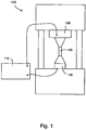
- An example system 100 is shown schematically in figure 1 , with a feedback controller 110 coupled to a motor assembly 120 and a load cell 130, with a device under test 140 positioned between the motor assembly 120 and load cell 130.
- the characteristics of the sample under test significantly affect the test system dynamics.
- parameters of the feedback loop compensator need to be adjusted based on the characteristics of the sample under test.
- the feedback compensator is based on PID (proportional, integral, derivative) type compensation, in which three parallel filters each influence the control signal.
- the input to these three filters is the error signal that is generated by subtracting a feedback signal, based on a measurement of the output, from the desired input signal.
- the feedback signal itself as the input to the derivative filter as this can be used to increase the damping of the system.
- Other types of control may also be used, such as time-domain control based on a state-space model of the system, linear controllers, lead-lag controllers, or fuzzy logic controllers.
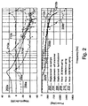
- the sample significantly affects the dynamics of the system, as shown in figure 2 .
- Lines 202a/b, 204a/b, and 206a/b show the magnitude and phase of a displacement measurement for three different samples and lines 208a/b, 210a/b, and 212a/b show the magnitude (a) and phase (b) of a force measurement for three different springs.
- the parameters of the controller such as the gains of the proportional, integral and derivative filters in a PID controller, must be modified for each sample under test.
- the process of determining parameters to use in the feedback loop compensator is automated.
- the system dynamics of the combination of the test machine and the sample under test must be identified. This can be accomplished using system identification techniques that are well-known.
- the output of the system identification is a frequency-domain representation of the system. It is desirable that the representation has adequate resolution to identify all of the dynamics within the frequency bandwidth of the control system.
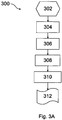
- Figure 3 A shows a generalized representation of the process 300 for determining the feedback parameters.
- a reference test signal is generated (302), as described below, and applied (304) to the test system.
- Feedback (output) signals for a material test system may include displacement, force, strain, acceleration, pressure, and others.
- the output is measured (306) and the time history data of the reference and the output signals are processed using Fourier methods to determine (308) a transfer function of the system.
- Feedback controller parameters discussed below, are calculated (310) by convolving the controller's filters with the measured transfer function.
- the control parameters are then stored or output (312) for use in testing.
- the reference test signal is typically voltage or current and the system identification is performed with the controller operating in an open-loop configuration.
- the reference test signal should be designed to contain frequency content consistent with the frequency and bandwidth of the signal to be used as input during the testing.
- This reference signal can be designed using random, chirp, impulse, or swept sine signals or combinations of signals.
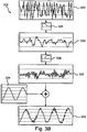
- the reference test signal 320 is a filtered random noise signal 322 superimposed on a small-amplitude low-frequency carrier wave 324, such as a 2 Hz sine wave, and is generated (302) as shown in figure 3B .
- the filter parameters used for the random component may be based on the properties of the motor being controlled by the signal, hi some examples, each of several motor types has a unique high-pass filter and a low-pass filter used to shape the random waveform.
- the high pass corner frequency may be chosen to be at a frequency greater than the free-air resonance of the system.
- the noise signal 322 is passed through a low-pass filter 326 and a high-pass filter 328 before being superimposed on the carrier wave 324, producing intermediate waveforms 330 and 332.
- the combined amplitude of the reference test signal 320 is designed to be less than the intended command waveform amplitude. In some examples, the amplitude of the test signal is limited to less than 10 percent of the motor or sensor capacities. Such settings are motor-specific and customized to a particular set of test equipment.
- the filtered random noise reference test signal 320 covers the full bandwidth of frequencies seen in the test, providing a good basis for determining the system transfer function.
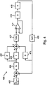
- An example feedback controller 400 is shown in figure 4 .
- the input command signal 402 is summed with a negative feedback signal and then passed through a notch filter 404.
- the notch filter is used to minimize the gain of resonances that cannot be minimized using the derivative inner loop, and is characterized by a filter parameter N.
- the reference test signal is provided to a proportional control block 406 and integral control block 408.
- the differential control block 410 takes the feedback signal as its input directly.
- the P, I, and D control outputs are summed (with D inverted) to form the updated test control signal, which is converted to an analog control signal in digital-to-analog converter (D2A) 412.
- D2A digital-to-analog converter
- the analog control signal is amplified in a transconductance amplifier 414 with current feedback before being provided to the test equipment 416.
- the combined test mechanism and sample system is represented by a single transfer function G.
- a sensor 418 having transfer function H provides the feedback signal to an analog-to-digital converter (A2D) 420.
- A2D analog-to-digital converter
- the individual blocks represented in figure 4 are for example only, and each may be implemented in a number of ways, including in hardware and software, and as discrete components/steps or integrated in various combinations.
- the sensor 418 may have a digital output, eliminating the need for A2D converter 420.
- the feedback controller parameters N, P, I, and D are calculated by convolving the controller's filters with the measured transfer function. Determination of the gain values for the controller's parameters involves balancing various specifications. These specifications may include gain and phase margins, time domain specifications, power specifications, bandwidth, disturbance rejection specifications and others. The specifications are used, among other things, to protect the sample and the test equipment from being damaged by inappropriate input values, such as values that exceed the capabilities of the system or that would cause destructive manipulation of the device under test (assuming that is not the goal of the test).
- Errors may occur due to, for example, non-linearities in the sample, friction in the sample or test system, or sensor noise, to name a few. Such errors can cause incorrect estimates of transfer function gain and phase which can then result in calculation of incorrect controller parameters. With incorrect parameters, the system may become unstable when the controller is operated in a closed-loop configuration. If the system is allowed to operate with an unstable controller configuration, the sample is likely to be damaged, and elements of the machine may also be damaged.
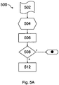
- an automated system implements a stability check before the system is allowed to implement the calculated parameters and perform normal testing.
- the calculated parameters are loaded (502), and the system is allowed to start operation.
- constraints are placed (504) on the feedback channel. These may include constraining the maximum and minimum value for the feedback channel, for example. Thresholds are set such that machine operation is discontinued if any of these thresholds are exceeded.
- a stability test waveform is applied (506) and the resulting operation is monitored (508) automatically. If none of the thresholds are exceeded, the system is deemed stable and normal testing is allowed (512). If thresholds are exceeded, then normal testing is prevented (514).
- One method of stopping the test system if a threshold has been exceeded is to immediately switch into the open loop mode at the mean value of the test waveform.
- a further improvement to this method is to also switch into a controller mode that uses the derivative filter. This will minimize the oscillations that may occur with unstable controllers.
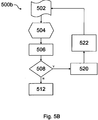
- the system dynamics are re-evaluated based on the stability test waveform if the system fails the threshold test.
- the threshold is exceeded (508) in modified process 500b
- the system transfer function is re-evaluated and a new transfer function is determined (520), and new controller parameters are calculated (522).
- the new controller parameters may be determined by convolving the new transfer function with the filters as before. These new controller parameters are provided to the stability test process and the test is repeated. Once the system converges on a stable set of parameters, the response will be within the threshold and the command waveform can be applied (512).
- the stability test waveform takes the form of two square waves at 1 Hz, centered at the desired command waveform's mean position.
- the square waves are of small amplitude, typically 5 percent of the desired command waveform's amplitude.
- the stability test waveform amplitude will be a greater percentage, but still less in absolute value than the command waveform amplitude.
- the stability test waveform takes the form of an attenuated or low-frequency version of the desired command waveform, and the error thresholds may vary with the test signal.
- a slow (e.g., 0.5 Hz) triangle or sin wave with a peak magnitude of 95 percent of the requested amplitude may be used as the test input, and the error threshold tracks to +/- 5 percent of each desired waveform point throughout the wave.
- Such a slow test waveform can help confirm that the test system, including the sample, has a linear response, as is often assumed.
- the attenuated value of the test waveform may be set based on the nature of the sample, e.g., a weaker material being tested may use only 80 percent of the desired command signal, while a sample known to be robust may use a full-strength test signal matching the amplitude of the desired command signal.
- the test system outputs to the user the reason the test was halted. That is, it may output which threshold was exceeded, and if known, what control parameter or what aspect of the input signal led to the system exceeding that threshold.
- the stability test waveform is a combination of the large-amplitude, low-frequency waveform described above with a smaller and higher-frequency signal, such as a square, chirp, or noise waveform. Superposing the higher-frequency signal on the lower-frequency carrier waveform may yield confirmation of full-band stability over potentially non-linear sample characteristics.
Landscapes
- Engineering & Computer Science (AREA)
- Health & Medical Sciences (AREA)
- Artificial Intelligence (AREA)
- Computer Vision & Pattern Recognition (AREA)
- Evolutionary Computation (AREA)
- Medical Informatics (AREA)
- Software Systems (AREA)
- Physics & Mathematics (AREA)
- General Physics & Mathematics (AREA)
- Automation & Control Theory (AREA)
- Investigating Strength Of Materials By Application Of Mechanical Stress (AREA)
- Feedback Control In General (AREA)
Claims (9)
- Verfahren zur Bestätigung der Stabilität eines Regelungssystems (400) für ein Materialprüfsystem, wobei das Verfahren umfasst:Bestimmen spezifizierter Filterparameter (406, 408, 410) für das Regelungssystem (400) durch:Erzeugen eines zufälligen Störsignals (322);Anwenden eines Tiefpassfilters (326) auf das zufällige Störsignal, um ein erstes gefiltertes Signal (330) zu produzieren;Anwenden eines Hochpassfilters (328) auf das erste gefilterte Signal, um ein zweites gefiltertes Signal (332) zu produzieren;Überlagern des zweiten gefilterten Signals auf eine sinusförmige Wellenform (324) um eine Referenz-Prüfwellenform (320) zu produzieren;Anwenden (304) der Referenz-Prüfwellenform auf ein zu prüfendes System (100);Messen der Ausgangsgröße (306) des zu prüfenden Systems;Bestimmen einer Übertragungsfunktion (308) des zu prüfenden Systems; undKonvolvieren der Übertragungsfunktion mit den Filtern des Regelungssystems (400), um die Filterparameter (310) zu produzieren;Betreiben des Regelungssystems in einer Regelkreiskonfiguration und Eingeben eines Stabilitätsprüfsignals (506) mit einer vorbestimmten Wellenform in das Regelungssystem;Automatische Überwachung der Ausgangsgröße des Materialprüfsystems;Einstellen eines Höchst- und Mindestschwellenwertes für den Feedback-Kanal des Regelkreis-Regelungssystems (400);Automatisches Vergleichen (508) der Ausgangsgröße mit den Schwellenwerten;wenn die Ausgangsgröße einen von beiden Schwellenwerten überschreitet, Verhindern der Eingabe eines Befehlssignals in das Regelungssystem; undwenn die Ausgangsgröße einen von beiden Schwellenwerten nicht überschreitet, Erlauben der Eingabe eines Befehlssignals (512) in das Regelungssystem,wobei das Stabilitätsprüfsignal eine gedämpfte oder Niederfrequenzversion des Befehlssignals umfasst.
- Verfahren nach Anspruch 1, wobei das Stabilitätsprüfsignal (506) die Form von zwei Rechteckwellen annimmt, die in der mittleren Position des Befehlssignals (512) zentriert sind.
- Verfahren nach Anspruch 2, wobei die Rechteckwellen eine Frequenz von 1 Hz aufweisen.
- Verfahren nach Anspruch 1, wobei das Stabilitätsprüfsignal (506) die Form einer Wellenform annimmt, die einer Wellenform des Befehlssignals entspricht und eine Amplitude von 95 Prozent der Amplitude (512) des Befehlssignals aufweist.
- Verfahren nach Anspruch 1, wobei der Schwellenwert mit dem Stabilitätsprüfsignal (506) variiert.
- Verfahren nach Anspruch 5, wobei der Schwellenwert ein Prozentsatz der Amplitude des Stabilitätsprüfsignals ist.
- Verfahren nach Anspruch 1, wobei das Stabilitätsprüfsignal (506) eine Kombination einer Niederfrequenz- und leicht gedämpften Version des Befehlssignals (512) und eines Hochfrequenzsignals kleiner Amplitude umfasst.
- Verfahren nach Anspruch 1, wobei, wenn die Ausgangsgröße die Schwellenwerte überschreitet, das Verfahren ferner umfasst:Bestimmen einer Übertragungsfunktion des Materialprüfsystems;Berechnen von Parametern für Filter des Regelungssystems;Laden der berechneten Parameter in die Filter; undWiederholen der Schritte des Anspruchs 1.
- Verfahren nach Anspruch 8, wobei das Berechnen der Parameter das Konvolvieren der Übertragungsfunktion mit den Filtern umfasst, um die Parameter zu produzieren.
Applications Claiming Priority (2)
| Application Number | Priority Date | Filing Date | Title |
|---|---|---|---|
| US17475609P | 2009-05-01 | 2009-05-01 | |
| PCT/US2010/033164 WO2010127243A1 (en) | 2009-05-01 | 2010-04-30 | Feedback controller parameter generation with stability monitoring |
Publications (2)
| Publication Number | Publication Date |
|---|---|
| EP2425305A1 EP2425305A1 (de) | 2012-03-07 |
| EP2425305B1 true EP2425305B1 (de) | 2016-06-08 |
Family
ID=42670619
Family Applications (1)
| Application Number | Title | Priority Date | Filing Date |
|---|---|---|---|
| EP10731621.8A Active EP2425305B1 (de) | 2009-05-01 | 2010-04-30 | Erzeugung von regelungsparametern mit stabilitätsüberwachung |
Country Status (5)
| Country | Link |
|---|---|
| US (1) | US9594358B2 (de) |
| EP (1) | EP2425305B1 (de) |
| CN (2) | CN106168756A (de) |
| HK (1) | HK1231575A1 (de) |
| WO (1) | WO2010127243A1 (de) |
Families Citing this family (5)
| Publication number | Priority date | Publication date | Assignee | Title |
|---|---|---|---|---|
| US9506782B2 (en) | 2013-04-24 | 2016-11-29 | Bose Corporation | Apparatus and method for applying a load to a material |
| US11371923B2 (en) | 2017-10-03 | 2022-06-28 | Waters Technologies Corporation | Automatic system compliance estimation and correction for mechanical testing systems |
| WO2019074719A1 (en) | 2017-10-09 | 2019-04-18 | Waters Technologies Corporation | CONTINUOUS DETERMINATION OF MEDIUM RIGIDITY AND LOAD GAIN FOR ADAPTIVE ACTUATOR CONTROL |
| WO2019074721A1 (en) | 2017-10-09 | 2019-04-18 | Waters Technologies Corporation | DETERMINING DYNAMIC PARAMETERS OF AN ADAPTIVE ACTUATOR CONTROL USING A MECHANICAL TEST DEVICE |
| US11843301B2 (en) | 2019-01-22 | 2023-12-12 | Waters Technologies Corporation | Linear motor |
Family Cites Families (13)
| Publication number | Priority date | Publication date | Assignee | Title |
|---|---|---|---|---|
| US3648031A (en) * | 1970-10-30 | 1972-03-07 | Collins Radio Co | Control system filtering technique |
| US4006351A (en) * | 1974-11-11 | 1977-02-01 | James Nickolas Constant | Recursive filter implemented as a matched clutter filter |
| DE3316138A1 (de) * | 1983-05-03 | 1984-11-08 | Alfons Dr.-Ing. 8000 München Schmidt | Verfahren und einrichtung zum steuern und regeln von schwingungs- und betriebsfestigkeitspruefanlagen |
| US5517426A (en) * | 1992-10-29 | 1996-05-14 | Underwood; Marcos A. | Apparatus and method for adaptive closed loop control of shock testing system |
| GB9319788D0 (en) * | 1993-09-24 | 1993-11-10 | Instron Ltd | Structure testing machine |
| US5623402A (en) * | 1994-02-10 | 1997-04-22 | Schenck Pegasus Corporation | Multi-channel inverse control using adaptive finite impulse response filters |
| JPH10224264A (ja) * | 1997-02-07 | 1998-08-21 | Pfu Ltd | 直接拡散型のスペクトラム拡散通信システム |
| US7031949B2 (en) * | 1998-01-22 | 2006-04-18 | Mts Systems Corporation | Method and apparatus for generating input signals in a physical system |
| US6405599B1 (en) * | 2000-01-13 | 2002-06-18 | Bose Corporation | Frictionless motor material testing |
| JP2004317345A (ja) * | 2003-04-17 | 2004-11-11 | Agilent Technol Inc | 狭帯域増幅器およびインピーダンス測定装置 |
| CN100419703C (zh) * | 2003-12-16 | 2008-09-17 | 联想(北京)有限公司 | 计算机稳定性测试系统及方法 |
| CN100468039C (zh) * | 2005-10-13 | 2009-03-11 | 河南科技大学 | 一种数据自动采集拉伸蠕变测试装置和方法 |
| GB0616590D0 (en) | 2006-08-21 | 2006-09-27 | Instron Ltd | Tuning of materials testing machine |
-
2010
- 2010-04-30 CN CN201610575239.0A patent/CN106168756A/zh active Pending
- 2010-04-30 WO PCT/US2010/033164 patent/WO2010127243A1/en not_active Ceased
- 2010-04-30 EP EP10731621.8A patent/EP2425305B1/de active Active
- 2010-04-30 US US12/770,868 patent/US9594358B2/en active Active
- 2010-04-30 CN CN2010800186053A patent/CN102414628A/zh active Pending
-
2017
- 2017-05-18 HK HK17105000.8A patent/HK1231575A1/zh unknown
Also Published As
| Publication number | Publication date |
|---|---|
| WO2010127243A1 (en) | 2010-11-04 |
| CN106168756A (zh) | 2016-11-30 |
| US20100280787A1 (en) | 2010-11-04 |
| EP2425305A1 (de) | 2012-03-07 |
| US9594358B2 (en) | 2017-03-14 |
| HK1231575A1 (zh) | 2017-12-22 |
| CN102414628A (zh) | 2012-04-11 |
Similar Documents
| Publication | Publication Date | Title |
|---|---|---|
| EP2425305B1 (de) | Erzeugung von regelungsparametern mit stabilitätsüberwachung | |
| US9600000B2 (en) | Method and device for active control of mechanical vibrations by implementation of a control law consisting of a central corrector and a Youla parameter | |
| JP5180212B2 (ja) | 材料試験装置の調節方法 | |
| JP7477670B2 (ja) | 床フィードフォワード補助を備えた精密振動絶縁システム | |
| JP7348977B2 (ja) | 変化するシステムパラメーターのリアルタイム補償を有する検査システム | |
| US9658627B2 (en) | Detection of imminent control instability | |
| US6189385B1 (en) | Shaking table and method of controlling the same | |
| Richiedei et al. | Shaper-Based Filters for the compensation of the load cell response in dynamic mass measurement | |
| Mojallizadeh et al. | Discrete-time differentiators in closed-loop control systems: experiments on electro-pneumatic system and rotary inverted pendulum | |
| US20130150984A1 (en) | Test system with configurable closed loop | |
| JP6468144B2 (ja) | 疲労試験機 | |
| JP7555317B2 (ja) | 試験装置 | |
| EP2989512B1 (de) | Vorrichtung und verfahren zum aufbringen einer last auf einem material | |
| JP7240340B2 (ja) | 振動試験装置 | |
| JP5465515B2 (ja) | Pid制御装置及びpid制御方法 | |
| Sun et al. | Robust and ultrafast response compensator applied to a levitation system | |
| O’hagan et al. | Experimental assessment of PID control for a uniaxial shake table | |
| JP5278333B2 (ja) | モータ制御装置 | |
| CN101189560B (zh) | 过程的控制 | |
| JP2008164463A (ja) | 試験機 | |
| JP5037024B2 (ja) | モータ制御装置 | |
| JP3368182B2 (ja) | 材料試験機 | |
| Chen et al. | Active vibration control enabled by intelligent excitation adaptability for frequency-variable excitations | |
| CN114738349B (zh) | 一种飞机振动疲劳测试试验中的加载补偿系统及其方法 | |
| Della Flora et al. | Design of a robust model reference adaptive voltage controller for an electrodynamic shaker |
Legal Events
| Date | Code | Title | Description |
|---|---|---|---|
| PUAI | Public reference made under article 153(3) epc to a published international application that has entered the european phase |
Free format text: ORIGINAL CODE: 0009012 |
|
| 17P | Request for examination filed |
Effective date: 20111013 |
|
| AK | Designated contracting states |
Kind code of ref document: A1 Designated state(s): AT BE BG CH CY CZ DE DK EE ES FI FR GB GR HR HU IE IS IT LI LT LU LV MC MK MT NL NO PL PT RO SE SI SK SM TR |
|
| DAX | Request for extension of the european patent (deleted) | ||
| 17Q | First examination report despatched |
Effective date: 20130402 |
|
| RAP1 | Party data changed (applicant data changed or rights of an application transferred) |
Owner name: TA INSTRUMENTS-WATERS LLC |
|
| GRAP | Despatch of communication of intention to grant a patent |
Free format text: ORIGINAL CODE: EPIDOSNIGR1 |
|
| INTG | Intention to grant announced |
Effective date: 20160201 |
|
| GRAS | Grant fee paid |
Free format text: ORIGINAL CODE: EPIDOSNIGR3 |
|
| GRAA | (expected) grant |
Free format text: ORIGINAL CODE: 0009210 |
|
| AK | Designated contracting states |
Kind code of ref document: B1 Designated state(s): AT BE BG CH CY CZ DE DK EE ES FI FR GB GR HR HU IE IS IT LI LT LU LV MC MK MT NL NO PL PT RO SE SI SK SM TR |
|
| REG | Reference to a national code |
Ref country code: GB Ref legal event code: FG4D |
|
| REG | Reference to a national code |
Ref country code: CH Ref legal event code: EP |
|
| REG | Reference to a national code |
Ref country code: IE Ref legal event code: FG4D |
|
| REG | Reference to a national code |
Ref country code: DE Ref legal event code: R096 Ref document number: 602010033929 Country of ref document: DE |
|
| REG | Reference to a national code |
Ref country code: AT Ref legal event code: REF Ref document number: 805660 Country of ref document: AT Kind code of ref document: T Effective date: 20160715 |
|
| REG | Reference to a national code |
Ref country code: LT Ref legal event code: MG4D |
|
| REG | Reference to a national code |
Ref country code: NL Ref legal event code: MP Effective date: 20160608 |
|
| PG25 | Lapsed in a contracting state [announced via postgrant information from national office to epo] |
Ref country code: LT Free format text: LAPSE BECAUSE OF FAILURE TO SUBMIT A TRANSLATION OF THE DESCRIPTION OR TO PAY THE FEE WITHIN THE PRESCRIBED TIME-LIMIT Effective date: 20160608 Ref country code: FI Free format text: LAPSE BECAUSE OF FAILURE TO SUBMIT A TRANSLATION OF THE DESCRIPTION OR TO PAY THE FEE WITHIN THE PRESCRIBED TIME-LIMIT Effective date: 20160608 Ref country code: NO Free format text: LAPSE BECAUSE OF FAILURE TO SUBMIT A TRANSLATION OF THE DESCRIPTION OR TO PAY THE FEE WITHIN THE PRESCRIBED TIME-LIMIT Effective date: 20160908 |
|
| REG | Reference to a national code |
Ref country code: AT Ref legal event code: MK05 Ref document number: 805660 Country of ref document: AT Kind code of ref document: T Effective date: 20160608 |
|
| PG25 | Lapsed in a contracting state [announced via postgrant information from national office to epo] |
Ref country code: NL Free format text: LAPSE BECAUSE OF FAILURE TO SUBMIT A TRANSLATION OF THE DESCRIPTION OR TO PAY THE FEE WITHIN THE PRESCRIBED TIME-LIMIT Effective date: 20160608 Ref country code: GR Free format text: LAPSE BECAUSE OF FAILURE TO SUBMIT A TRANSLATION OF THE DESCRIPTION OR TO PAY THE FEE WITHIN THE PRESCRIBED TIME-LIMIT Effective date: 20160909 Ref country code: LV Free format text: LAPSE BECAUSE OF FAILURE TO SUBMIT A TRANSLATION OF THE DESCRIPTION OR TO PAY THE FEE WITHIN THE PRESCRIBED TIME-LIMIT Effective date: 20160608 Ref country code: SE Free format text: LAPSE BECAUSE OF FAILURE TO SUBMIT A TRANSLATION OF THE DESCRIPTION OR TO PAY THE FEE WITHIN THE PRESCRIBED TIME-LIMIT Effective date: 20160608 Ref country code: ES Free format text: LAPSE BECAUSE OF FAILURE TO SUBMIT A TRANSLATION OF THE DESCRIPTION OR TO PAY THE FEE WITHIN THE PRESCRIBED TIME-LIMIT Effective date: 20160608 |
|
| PG25 | Lapsed in a contracting state [announced via postgrant information from national office to epo] |
Ref country code: EE Free format text: LAPSE BECAUSE OF FAILURE TO SUBMIT A TRANSLATION OF THE DESCRIPTION OR TO PAY THE FEE WITHIN THE PRESCRIBED TIME-LIMIT Effective date: 20160608 Ref country code: SK Free format text: LAPSE BECAUSE OF FAILURE TO SUBMIT A TRANSLATION OF THE DESCRIPTION OR TO PAY THE FEE WITHIN THE PRESCRIBED TIME-LIMIT Effective date: 20160608 Ref country code: CZ Free format text: LAPSE BECAUSE OF FAILURE TO SUBMIT A TRANSLATION OF THE DESCRIPTION OR TO PAY THE FEE WITHIN THE PRESCRIBED TIME-LIMIT Effective date: 20160608 Ref country code: IS Free format text: LAPSE BECAUSE OF FAILURE TO SUBMIT A TRANSLATION OF THE DESCRIPTION OR TO PAY THE FEE WITHIN THE PRESCRIBED TIME-LIMIT Effective date: 20161008 Ref country code: IT Free format text: LAPSE BECAUSE OF FAILURE TO SUBMIT A TRANSLATION OF THE DESCRIPTION OR TO PAY THE FEE WITHIN THE PRESCRIBED TIME-LIMIT Effective date: 20160608 Ref country code: RO Free format text: LAPSE BECAUSE OF FAILURE TO SUBMIT A TRANSLATION OF THE DESCRIPTION OR TO PAY THE FEE WITHIN THE PRESCRIBED TIME-LIMIT Effective date: 20160608 |
|
| PG25 | Lapsed in a contracting state [announced via postgrant information from national office to epo] |
Ref country code: PT Free format text: LAPSE BECAUSE OF FAILURE TO SUBMIT A TRANSLATION OF THE DESCRIPTION OR TO PAY THE FEE WITHIN THE PRESCRIBED TIME-LIMIT Effective date: 20161010 Ref country code: BE Free format text: LAPSE BECAUSE OF FAILURE TO SUBMIT A TRANSLATION OF THE DESCRIPTION OR TO PAY THE FEE WITHIN THE PRESCRIBED TIME-LIMIT Effective date: 20160608 Ref country code: SM Free format text: LAPSE BECAUSE OF FAILURE TO SUBMIT A TRANSLATION OF THE DESCRIPTION OR TO PAY THE FEE WITHIN THE PRESCRIBED TIME-LIMIT Effective date: 20160608 Ref country code: AT Free format text: LAPSE BECAUSE OF FAILURE TO SUBMIT A TRANSLATION OF THE DESCRIPTION OR TO PAY THE FEE WITHIN THE PRESCRIBED TIME-LIMIT Effective date: 20160608 Ref country code: PL Free format text: LAPSE BECAUSE OF FAILURE TO SUBMIT A TRANSLATION OF THE DESCRIPTION OR TO PAY THE FEE WITHIN THE PRESCRIBED TIME-LIMIT Effective date: 20160608 |
|
| REG | Reference to a national code |
Ref country code: DE Ref legal event code: R097 Ref document number: 602010033929 Country of ref document: DE |
|
| PLBE | No opposition filed within time limit |
Free format text: ORIGINAL CODE: 0009261 |
|
| STAA | Information on the status of an ep patent application or granted ep patent |
Free format text: STATUS: NO OPPOSITION FILED WITHIN TIME LIMIT |
|
| 26N | No opposition filed |
Effective date: 20170309 |
|
| PG25 | Lapsed in a contracting state [announced via postgrant information from national office to epo] |
Ref country code: SI Free format text: LAPSE BECAUSE OF FAILURE TO SUBMIT A TRANSLATION OF THE DESCRIPTION OR TO PAY THE FEE WITHIN THE PRESCRIBED TIME-LIMIT Effective date: 20160608 Ref country code: DK Free format text: LAPSE BECAUSE OF FAILURE TO SUBMIT A TRANSLATION OF THE DESCRIPTION OR TO PAY THE FEE WITHIN THE PRESCRIBED TIME-LIMIT Effective date: 20160608 |
|
| REG | Reference to a national code |
Ref country code: CH Ref legal event code: PL |
|
| REG | Reference to a national code |
Ref country code: IE Ref legal event code: MM4A |
|
| REG | Reference to a national code |
Ref country code: FR Ref legal event code: ST Effective date: 20171229 |
|
| PG25 | Lapsed in a contracting state [announced via postgrant information from national office to epo] |
Ref country code: FR Free format text: LAPSE BECAUSE OF NON-PAYMENT OF DUE FEES Effective date: 20170502 Ref country code: MC Free format text: LAPSE BECAUSE OF FAILURE TO SUBMIT A TRANSLATION OF THE DESCRIPTION OR TO PAY THE FEE WITHIN THE PRESCRIBED TIME-LIMIT Effective date: 20160608 |
|
| PG25 | Lapsed in a contracting state [announced via postgrant information from national office to epo] |
Ref country code: LU Free format text: LAPSE BECAUSE OF NON-PAYMENT OF DUE FEES Effective date: 20170430 Ref country code: CH Free format text: LAPSE BECAUSE OF NON-PAYMENT OF DUE FEES Effective date: 20170430 Ref country code: LI Free format text: LAPSE BECAUSE OF NON-PAYMENT OF DUE FEES Effective date: 20170430 |
|
| PG25 | Lapsed in a contracting state [announced via postgrant information from national office to epo] |
Ref country code: IE Free format text: LAPSE BECAUSE OF NON-PAYMENT OF DUE FEES Effective date: 20170430 |
|
| PG25 | Lapsed in a contracting state [announced via postgrant information from national office to epo] |
Ref country code: MT Free format text: LAPSE BECAUSE OF NON-PAYMENT OF DUE FEES Effective date: 20170430 |
|
| PG25 | Lapsed in a contracting state [announced via postgrant information from national office to epo] |
Ref country code: HU Free format text: LAPSE BECAUSE OF FAILURE TO SUBMIT A TRANSLATION OF THE DESCRIPTION OR TO PAY THE FEE WITHIN THE PRESCRIBED TIME-LIMIT; INVALID AB INITIO Effective date: 20100430 |
|
| PG25 | Lapsed in a contracting state [announced via postgrant information from national office to epo] |
Ref country code: BG Free format text: LAPSE BECAUSE OF FAILURE TO SUBMIT A TRANSLATION OF THE DESCRIPTION OR TO PAY THE FEE WITHIN THE PRESCRIBED TIME-LIMIT Effective date: 20160608 |
|
| PG25 | Lapsed in a contracting state [announced via postgrant information from national office to epo] |
Ref country code: CY Free format text: LAPSE BECAUSE OF NON-PAYMENT OF DUE FEES Effective date: 20160608 |
|
| PG25 | Lapsed in a contracting state [announced via postgrant information from national office to epo] |
Ref country code: MK Free format text: LAPSE BECAUSE OF FAILURE TO SUBMIT A TRANSLATION OF THE DESCRIPTION OR TO PAY THE FEE WITHIN THE PRESCRIBED TIME-LIMIT Effective date: 20160608 |
|
| PG25 | Lapsed in a contracting state [announced via postgrant information from national office to epo] |
Ref country code: TR Free format text: LAPSE BECAUSE OF FAILURE TO SUBMIT A TRANSLATION OF THE DESCRIPTION OR TO PAY THE FEE WITHIN THE PRESCRIBED TIME-LIMIT Effective date: 20160608 |
|
| PG25 | Lapsed in a contracting state [announced via postgrant information from national office to epo] |
Ref country code: HR Free format text: LAPSE BECAUSE OF FAILURE TO SUBMIT A TRANSLATION OF THE DESCRIPTION OR TO PAY THE FEE WITHIN THE PRESCRIBED TIME-LIMIT Effective date: 20160608 |
|
| P01 | Opt-out of the competence of the unified patent court (upc) registered |
Effective date: 20230609 |
|
| P02 | Opt-out of the competence of the unified patent court (upc) changed |
Effective date: 20230619 |
|
| PGFP | Annual fee paid to national office [announced via postgrant information from national office to epo] |
Ref country code: GB Payment date: 20250319 Year of fee payment: 16 |
|
| PGFP | Annual fee paid to national office [announced via postgrant information from national office to epo] |
Ref country code: DE Payment date: 20250319 Year of fee payment: 16 |