EP2425301B1 - Système de mesure de temps relatif ayant une précision de l'ordre de la nanoseconde - Google Patents
Système de mesure de temps relatif ayant une précision de l'ordre de la nanoseconde Download PDFInfo
- Publication number
- EP2425301B1 EP2425301B1 EP10725289.2A EP10725289A EP2425301B1 EP 2425301 B1 EP2425301 B1 EP 2425301B1 EP 10725289 A EP10725289 A EP 10725289A EP 2425301 B1 EP2425301 B1 EP 2425301B1
- Authority
- EP
- European Patent Office
- Prior art keywords
- time
- frequency
- source
- timing
- pulse
- Prior art date
- Legal status (The legal status is an assumption and is not a legal conclusion. Google has not performed a legal analysis and makes no representation as to the accuracy of the status listed.)
- Active
Links
Images


Classifications
-
- G—PHYSICS
- G04—HOROLOGY
- G04G—ELECTRONIC TIME-PIECES
- G04G7/00—Synchronisation
-
- G—PHYSICS
- G01—MEASURING; TESTING
- G01S—RADIO DIRECTION-FINDING; RADIO NAVIGATION; DETERMINING DISTANCE OR VELOCITY BY USE OF RADIO WAVES; LOCATING OR PRESENCE-DETECTING BY USE OF THE REFLECTION OR RERADIATION OF RADIO WAVES; ANALOGOUS ARRANGEMENTS USING OTHER WAVES
- G01S19/00—Satellite radio beacon positioning systems; Determining position, velocity or attitude using signals transmitted by such systems
- G01S19/01—Satellite radio beacon positioning systems transmitting time-stamped messages, e.g. GPS [Global Positioning System], GLONASS [Global Orbiting Navigation Satellite System] or GALILEO
- G01S19/13—Receivers
- G01S19/31—Acquisition or tracking of other signals for positioning
-
- G—PHYSICS
- G01—MEASURING; TESTING
- G01S—RADIO DIRECTION-FINDING; RADIO NAVIGATION; DETERMINING DISTANCE OR VELOCITY BY USE OF RADIO WAVES; LOCATING OR PRESENCE-DETECTING BY USE OF THE REFLECTION OR RERADIATION OF RADIO WAVES; ANALOGOUS ARRANGEMENTS USING OTHER WAVES
- G01S19/00—Satellite radio beacon positioning systems; Determining position, velocity or attitude using signals transmitted by such systems
- G01S19/38—Determining a navigation solution using signals transmitted by a satellite radio beacon positioning system
- G01S19/39—Determining a navigation solution using signals transmitted by a satellite radio beacon positioning system the satellite radio beacon positioning system transmitting time-stamped messages, e.g. GPS [Global Positioning System], GLONASS [Global Orbiting Navigation Satellite System] or GALILEO
- G01S19/42—Determining position
-
- G—PHYSICS
- G04—HOROLOGY
- G04G—ELECTRONIC TIME-PIECES
- G04G7/00—Synchronisation
- G04G7/02—Synchronisation by radio
Definitions
- the present invention relates generally to time measurement systems and more particularly to relative time measurement systems.
- Certain embodiments of the present invention seek to provide a system having one nanosecond relative time measurement capability for non-collocated units which is characterized by continuous and instantaneous relative time measurement. Time offset between non-collocated frequency sources at discrete points of time is determined; and frequency drift between the frequency sources is disciplined.
- a method for instantaneous and continuous determination of a relative time offset between non-collocated frequency sources having a relative frequency drift therebetween, the determination being carried out at a required nanosecond level accuracy comprising disciplining of frequency drift between the frequency sources at a frequency domain including computing, and applying to the frequency sources, corrections of a relative frequency drift between each frequency source and a single time source, the disciplining being limited by the following condition: the product of a duration of any time period extending between adjacent discrete points of time in a sequence of discrete points of time, multiplied by the sum of all frequency corrections effected during the time period and divided by a frequency value characterizing the frequency sources, is at least one order of magnitude less than the required accuracy; and determining time offset between the non-collocated frequency sources at each discrete point of time in the sequence of discrete points of time.
- a system for instantaneous and continuous nanosecond-level accuracy determination of a relative time offset between at least two non-collocated timing units comprising at least two non-collocated timing units located at known positions, each timing unit comprising a frequency source and a collocated receiver, each frequency source being disciplined at a frequency domain using a time source to generate corrections of the relative frequency drift between the frequency source and the time source so as to be limited by the following condition: the product of a duration of any time period extending between adjacent discrete points of time in a sequence of discrete points of time, multiplied by the sum of all frequency corrections effected during the time period and divided by a frequency value characterizing the frequency sources, is at least one order of magnitude less than the required accuracy, each receiver being synchronized by a synchronization signal supplied by the frequency source and being operative to receive an external signal stream defining a time-line and to derive therefrom a stream of pseudo-range sample and integrated
- the positions of non-collocated timing units are known at least at decimeter level.
- the computation unit is operative to determine time offset between corresponding periodic pulses generated by the two timing units respectively by applying a single difference technique to corresponding ones of the pairs, the corresponding ones being defined by at least one time line defined by at least one receiver.
- the frequency source is disciplined by an external time source serving as time source for both of the timing units and the nanosecond level accuracy measurement is produced for an unlimited time span.
- At least one of the timing units is mobile.
- the receiver might be operative to generate additional periodic pulses synchronized with the time source and to provide the additional periodic pulses to the frequency source and wherein the frequency source uses the additional pulses in order to correct frequency drift between the frequency source and the time source.
- each pulse generated by one timing unit and occurring at a first time is taken by the computation unit to correspond to that pulse from among the pulses generated by another timing unit, whose time of occurrence is closest to the first time.
- each timing unit includes a memory for storing at least a window of pulses, each pulse being associated with a time tag.
- the system also comprises at least first and second additional devices co-located with respective ones of the timing units wherein the additional devices operate synchronously based on input provided by their co-located timing units.
- the input comprises at least one of the synchronization signals supplied by the frequency source of its co-located timing unit and at least one periodic pulse generated by the receiver of its co-located timing unit.
- each additional device comprises a sensor, the system also comprising a processing unit operative to provide instantaneous and continuous nanosecond-level accuracy measurement of time elapsing between events occurring at the sensor and the sensor of the other additional system, the sensor being operative to receive an event and to perform an evaluation of a time period which has elapsed from receipt of the event back to a most recently generated pulse from among the periodic pulses generated by the timing unit co-located with the sensor, and wherein the evaluation of the time period is performed by counting the number of periods defined by the frequency source, elapsing between reception of the event back to a most recently generated pulse and summing the number with a difference between phases defined by the frequency source at a most recently generated pulse and at the event; wherein the processing unit is operative to compute a sum of the time offset and the difference between the time periods evaluated by the sensors respectively, thereby to measure time which has elapsed between events occurring at the sensors.
- the events respectively comprise reception of a single external occurrence by the sensors respectively.
- each of the events comprises an electromagnetic pulse having a rise/fall time which is an order of magnitude less than the accuracy of the measurement of time elapsing between events.
- the determining of time offset employs a common view time transfer procedure.
- the time source comprises a GPS time source.
- the external signal stream, defining a time-line is provided to the receiver by the time source.
- the receiver supplies the frequency source with positioning data which is employed by the frequency source in order to correct frequency drift between the frequency source and the time source.
- a computer program product comprising a computer usable medium or computer readable storage medium, typically tangible, having a computer readable program code embodied therein, the computer readable program code adapted to be executed to implement any or all of the methods shown and described herein. It is appreciated that any or all of the computational steps shown and described herein may be computer-implemented. The operations in accordance with the teachings herein may be performed by a computer specially constructed for the desired purposes or by a general purpose computer specially configured for the desired purpose by a computer program stored in a computer readable storage medium.
- processors Any suitable processor, display and input means may be used to process, display, store and accept information, including computer programs, in accordance with some or all of the teachings of the present invention, such as but not limited to a conventional personal computer processor, workstation or other programmable device or computer or electronic computing device, either general-purpose or specifically constructed, for processing; a display screen and/or printer and/or speaker for displaying; machine-readable memory such as optical disks, CDROMs, magnetic-optical discs or other discs; RAMs, ROMs, EPROMs, EEPROMs, magnetic or optical or other cards, for storing, and keyboard or mouse for accepting.
- the term "process” as used above is intended to include any type of computation or manipulation or transformation of data represented as physical, e.g. electronic, phenomena which may occur or reside e.g. within registers and /or memories of a computer.
- the above devices may communicate via any conventional wired or wireless digital communication means, e.g. via a wired or cellular telephone network or a computer network such as the Internet.
- the apparatus of the present invention may include, according to certain embodiments of the invention, machine readable memory containing or otherwise storing a program of instructions which, when executed by the machine, implements some or all of the apparatus, methods, features and functionalities of the invention shown and described herein.
- the apparatus of the present invention may include, according to certain embodiments of the invention, a program as above which may be written in any conventional programming language, and optionally a machine for executing the program such as but not limited to a general purpose computer which may optionally be configured or activated in accordance with the teachings of the present invention. Any of the teachings incorporated herein may, wherever suitable, operate on signals representative of physical objects or substances.
- the term "computer” should be broadly construed to cover any kind of electronic device with data processing capabilities, including, by way of non-limiting example, personal computers, servers, computing system, communication devices, processors (e.g. digital signal processor (DSP), microcontrollers, field programmable gate array (FPGA), application specific integrated circuit (ASIC), etc.) and other electronic computing devices.
- processors e.g. digital signal processor (DSP), microcontrollers, field programmable gate array (FPGA), application specific integrated circuit (ASIC), etc.
- DSP digital signal processor
- FPGA field programmable gate array
- ASIC application specific integrated circuit
- Fig. 1 is a simplified semi-pictorial semi-functional block diagram illustration of a system for Relative Time Measurement between two or more non-collocated stations 20 and 30 with known coordinates, constructed and operative in accordance with certain embodiments of the present invention.
- Each station observes a Common External Signal (e.g. GNSS via GNSS antennae 25 and 35 respectively), produces time tagged samples (pseudo-range and integrated Doppler) based on a common external signal which may be generated by or generated responsive to a satellite 10 and senses a common external event.
- Each station computes a precise Time Period between an individual common sensed external event time tag and the time tag of the latest of the samples.
- a time offset Computation Unit 40 receives samples from stations A and B and computes a Time Offset between station 20's and station 30's clocks at sampling time e.g. using Equations 1 - 4 below.
- the time offset information is provided to a nanosecond accuracy processing unit 50 which accurately measures time elapsing between events at stations A and B all as described in detail below.
- the time offset computation performed by unit 40 is typically based on a conventional Single Difference (SD) algorithm e.g. as described in Bradford W. Parkinson and James J. Spilker, Global Positioning System: Theory and applications, Vol. II, Chapter 18, Eq. 9.
- SD Single Difference
- An instant Time Offset is computed between the stations 20 and 30's internal time scales using coherent pseudo-range and integrated Doppler Samples from each station and the Known Positions of the stations' antennae 25 and 35.
- the Single Difference (SD) algorithm implements the following linear combinations of coherent pseudo-range and carrier-phase (integrated Doppler), as follows (Equations 1 and 2):
- a provided by Station A of Fig. 1 include:
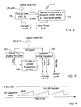
- Fig. 2 is a simplified semi-pictorial semi-functional block diagram illustration of an individual one of stations 20, 30 of Fig. 1 and its associated antenna 25 or 35 respectively.
- each station may comprise Timing Unit 100 and Sensor 110.
- Timing Unit 100 is capable of producing stable frequency and a corresponding PPS signal provided to the Sensor 110 unit. Additionally, Timing Unit 100 provides coherent pseudo-range and integrated Doppler Samples of the external signal as sensed by the station's antenna, 25 or 35.
- each Timing Unit 100 may comprise a Frequency Source 210 and a Receiver 220 of an external signal stream e.g. a stream of GNSS signals.
- the Receiver 220's internal oscillator is disciplined at a frequency domain by the Frequency Source 210.
- the Frequency source 210 itself is suitably disciplined at a frequency domain by global time aiding receiver 200 (e.g. second receiver) e.g. as follows:
- the Frequency Source 210 corrects its frequency drift limited by the following condition: the sum of all frequency corrections ( ⁇ F ) effected during the noted time period divided by disciplined frequency is at least one order of magnitude less than the required accuracy: dT ⁇ ⁇ ⁇ ⁇ F F 0 ⁇ 0.1 ns
- Fig. 4 is a graph of a System Error Budget of the relative time measurement system of Fig. 1 . As shown, in the illustrated embodiment, the error remains below 1 nanosecond.
- the continuous time measurement with nanosecond accuracy is based on a single difference (SD) algorithm and a relative frequency low drift capability between the updates. Nanosecond accuracy is achieved when single-difference technique noise is at order of 0.5 nanosecond (i.e. 15 cm) and relative frequency drift is one order less than required accuracy i.e. 0.1 nanosecond per one SD update period.
- SD single difference
- Timing Units 100's coordinates are known at the decimeter level (0.3 nanosecond)
- PPS output and frequency adding mechanisms in Timing Units are known to be of an order of 0.1 - 0.2 nanoseconds
- each pair of Timing Units 100 is calibrated once prior to their usage at a level of accuracy of 0.3 nanoseconds
- carrier phase measurements' noise is less than 1/30 nanosecond.
- System Error Budget is maintained below 1 nanosecond, as shown in Fig. 4 .
- Fig. 5 is a simplified functional block diagram of relative internal bias calibration apparatus in conjunction with a pair of timing units of the type shown in Fig. 3 .
- the relative internal bias calibration apparatus of Fig. 5 includes an external stable frequency source 300 and a Time Counter 310 as shown.
- An external frequency governs frequency sources 210 and 210' in Timing Units 100 and 100' respectively, in the frequency domain.
- an external stable frequency 300 governs Time Counter 310 used for evaluating the Time Offset between PPS signals of Timing Units 100 and 100'.
- Relative internal bias B AB typically comprises two components which are constant for a given pair of Timing Units 100 and 100': offset between hardware delays at RF lines and offset between delays of internal 1PPS generation.
- the offset between hardware delays at RF lines comprises e.g. differences in delays at antennas, cables, RF front ends and other hardware elements.
- the offset between delays of internal 1PPS generation comprises differences between thresholds of 1PPS generation circuits and external frequency locking loops. Both these offsets are correlated and thus typically calibrated as one Relative internal bias value.
- Hardware delays being relevant to GNSS receivers 220 and 220' in the Timing Units 100 and 100' only, may be calibrated as follows: an external stable frequency from source 300 governs each Timing Unit 100's frequency sources 210 thus eliminating any frequency drift between them, whereas Time Counter 310 ( Fig. 5 ) evaluates ⁇ t AB , the Time Offset between Timing Unit 100's PPS signals.
- Fig. 6 is a simplified flowchart illustration of a method for instantaneous and continuous determination of a relative time offset between non-collocated frequency sources such as those shown in Fig. 3 , having a relative frequency drift therebetween, the determination being carried out at a required nanosecond level accuracy, all operative in accordance with certain embodiments of the present invention.
- a particular advantage of certain embodiments of the present invention is that the system shown and described herein does not require preliminary time synchronization between the two platforms and is able to supply the relative time measurement for an unlimited time span.
- the two platform locations are presumed to be known with sub-decimeter level accuracy, whereas the distance between the platforms may increase up to a few dozen kilometers.
- software components of the present invention including programs and data may, if desired, be implemented in ROM (read only memory) form including CD-ROMs, EPROMs and EEPROMs, or may be stored in any other suitable computer-readable medium such as but not limited to disks of various kinds, cards of various kinds and RAMs.
- ROM read only memory
- EEPROM electrically erasable programmable read-only memory
- Components described herein as software may, alternatively, be implemented wholly or partly in hardware, if desired, using conventional techniques.
Landscapes
- Engineering & Computer Science (AREA)
- Physics & Mathematics (AREA)
- General Physics & Mathematics (AREA)
- Radar, Positioning & Navigation (AREA)
- Remote Sensing (AREA)
- Computer Networks & Wireless Communication (AREA)
- Position Fixing By Use Of Radio Waves (AREA)
- Measurement Of Unknown Time Intervals (AREA)
Claims (19)
- Procédé de détermination instantanée et continue d'un décalage temporel relatif entre des sources de fréquence non colocalisées présentant entre elles une dérive de fréquence relative, ladite détermination étant mise en oeuvre avec une précision requise au niveau nanoseconde, le procédé comprenant :l'application d'une discipline de dérive de fréquence entre les sources de fréquence dans un domaine de fréquence comprenant le calcul, et l'application aux sources de fréquence, de corrections d'une dérive de fréquence relative entre chaque source de fréquence et une source de temps unique, ladite application de discipline étant limitée par la condition suivante : le produit de la durée d'une période quelconque qui s'étend entre des points temporels discrets adjacents, dans une séquence de points temporels discrets, par la somme de toutes les corrections de fréquence effectuées durant ladite période, divisé par une valeur de fréquence qui caractérise les sources de fréquence, est au moins un ordre de grandeur inférieur à la précision requise ; etla détermination d'un décalage temporel entre lesdites sources de fréquence non colocalisées à chaque point temporel discret dans ladite séquence de points temporels discrets, en utilisant une technique de différence unique.
- Système de détermination instantanée et continue de la précision au niveau nanoseconde d'un décalage temporel relatif entre au moins deux unités de synchronisation non colocalisées (20, 30), le système comprenant :au moins deux unités de synchronisation non colocalisées (20, 30) situées à des positions connues, chaque unité de synchronisation comprenant une source de fréquence (210) et un récepteur colocalisé (200),une discipline étant appliquée à chaque dite source de fréquence (20) à un domaine de fréquence en utilisant une source de temps pour générer des corrections de la dérive de fréquence relative entre ladite source de fréquence (20) et ladite source de temps de manière à être limitée par la condition suivante : le produit de la durée d'une période quelconque, qui s'étend entre des points temporels discrets adjacents dans une séquence de points temporels discrets, par la somme de toutes les corrections de fréquence effectuées durant la période, divisé par une valeur de fréquence qui caractérise la source de fréquence (20), est au moins un ordre de grandeur inférieur à la précision requise,chaque dit récepteur (200) étant synchronisé par un signal de synchronisation fourni par ladite source de fréquence (210) et étant fonctionnel pour recevoir un flux de signal externe définissant une ligne temporelle et pour en dériver un flux de paires échantillon de pseudo-distance - échantillon Doppler intégré, de manière à générer, pour chaque paire individuelle dans au moins un sous-ensemble desdites paires, une impulsion périodique synchronisée avec ladite source de fréquence, de manière à définir ainsi une impulsion périodique correspondant à ladite paire individuelle et à sortir chaque paire individuelle dans ledit sous-ensemble, simultanément avec l'impulsion périodique correspondante de la paire individuelle ; etau moins une unité de calcul de décalage temporel fonctionnelle pour utiliser les positions connues desdites unités de synchronisation et au moins une paire d'échantillons depuis chacune desdites unités de synchronisation de manière à calculer respectivement un décalage temporel entre des impulsions périodiques générées par lesdites deux unités de synchronisation, en utilisant une technique de différence unique.
- Système selon la revendication 2, dans lequel les positions d'unités de synchronisation non colocalisées sont connues au moins au niveau décimétrique.
- Système selon la revendication 2, dans lequel ladite unité de calcul est fonctionnelle pour déterminer un décalage temporel entre des impulsions périodiques correspondantes générées par lesdites deux unités de synchronisation en appliquant respectivement une technique de différence unique à des paires correspondantes desdites paires, lesdites paires correspondantes étant définies par au moins une ligne temporelle définie par au moins un récepteur.
- Système selon la revendication 2, dans lequel une discipline est appliquée à ladite source de fréquence par une source de temps externe servant de source de temps pour les deux dites unités de synchronisation, et ladite mesure de précision au niveau nanoseconde est produite durant un intervalle de temps illimité.
- Système selon la revendication 2, dans lequel au moins une desdites unités de synchronisation est mobile.
- Système selon la revendication 2 dans lequel, dans chaque unité de synchronisation, ledit récepteur fournit à la source de fréquence des données de positionnement qui sont employées par la source de fréquence de manière à corriger une dérive de fréquence entre ladite source de fréquence et ladite source de temps.
- Système selon la revendication 2, dans lequel ledit récepteur est fonctionnel pour générer des impulsions périodiques additionnelles synchronisées avec la source de temps et pour fournir lesdites impulsions périodiques additionnelles à la source de fréquence, et dans lequel ladite source de fréquence utilise lesdites impulsions additionnelles de manière à corriger la dérive de fréquence entre ladite source de fréquence et ladite source de temps.
- Système selon la revendication 4, dans lequel chaque impulsion générée par une unité de synchronisation et se produisant à un premier temps est considérée par ladite unité de calcul comme correspondant à l'impulsion parmi les impulsions générées par une autre unité de synchronisation dont le temps d'occurrence est le plus proche dudit premier temps.
- Système selon la revendication 2, dans lequel chaque dite unité de synchronisation comprend une mémoire pour stocker au moins une fenêtre d'impulsions, chaque impulsion étant associée à un marqueur temporel.
- Système selon la revendication 2, comprenant également au moins des premier et deuxième dispositifs additionnels colocalisés avec des unités respectives parmi lesdites unités de synchronisation, dans lequel lesdits dispositifs additionnels fonctionnent de manière synchrone sur base de l'entrée fournie par leurs unités de synchronisation colocalisées.
- Système selon la revendication 11, dans lequel ladite entrée comprend au moins une entrée parmi lesdits signaux de synchronisation fournis par la source de fréquence de son unité de synchronisation colocalisée, et au moins une impulsion périodique générée par le récepteur de son unité de synchronisation colocalisée.
- Système selon la revendication 12, dans lequel chaque dit dispositif additionnel comprend un capteur, le système comprenant également une unité de traitement fonctionnelle pour fournir une mesure instantanée et continue de la précision au niveau nanoseconde du temps qui s'écoule entre des événements se produisant audit capteur et au capteur de l'autre système additionnel, le capteur étant fonctionnel pour recevoir un événement et pour mettre en oeuvre une évaluation d'une période qui s'est écoulée depuis la réception dudit événement à partir de l'impulsion générée le plus récemment parmi lesdites impulsions périodiques générées par l'unité de synchronisation colocalisée avec le capteur, et dans lequel ladite évaluation de ladite période est mise en oeuvre en comptant le nombre de périodes définies par ladite source de fréquence qui s'écoulent entre la réception dudit événement à partir de l'impulsion générée le plus récemment et en additionnant ledit nombre à une différence entre des phases définies par ladite source de fréquence à l'impulsion générée le plus récemment et audit événement ;
dans lequel ladite unité de traitement est fonctionnelle pour calculer la somme dudit décalage temporel et de la différence entre lesdites périodes évaluées respectivement par lesdits capteurs, pour mesurer ainsi le temps qui s'est écoulé entre des événements qui se produisent aux capteurs. - Système selon la revendication 13, dans lequel lesdits événements comprennent respectivement la réception d'une occurrence externe unique par lesdits capteurs.
- Système selon la revendication 13, dans lequel chacun desdits événements comprend une impulsion électromagnétique qui possède un temps de montée/descente d'un ordre de grandeur inférieur à ladite précision de ladite mesure du temps qui s'écoule entre des événements.
- Procédé selon la revendication 1, dans lequel ladite détermination de décalage temporel emploie une procédure de transfert de temps à vue commune.
- Procédé selon la revendication 1, dans lequel ladite source de temps comprend une source de temps de système de positionnement par satellites GNSS, soit Global Navigation Satellite System.
- Système selon la revendication 2, dans lequel ledit flux de signal externe qui définit une ligne temporelle est pourvu audit récepteur par ladite source de temps.
- Procédé selon la revendication 1, dans lequel ladite valeur de fréquence qui caractérise les sources de fréquence comprend une fréquence des sources de fréquence à un point de début de ladite période.
Applications Claiming Priority (2)
| Application Number | Priority Date | Filing Date | Title |
|---|---|---|---|
| IL198489A IL198489A (en) | 2009-04-30 | 2009-04-30 | Relative time measurement system with nanosecond precision |
| PCT/IL2010/000346 WO2010125569A1 (fr) | 2009-04-30 | 2010-04-29 | Système de mesure de temps relatif ayant une précision de l'ordre de la nanoseconde |
Publications (2)
| Publication Number | Publication Date |
|---|---|
| EP2425301A1 EP2425301A1 (fr) | 2012-03-07 |
| EP2425301B1 true EP2425301B1 (fr) | 2015-03-04 |
Family
ID=42358351
Family Applications (1)
| Application Number | Title | Priority Date | Filing Date |
|---|---|---|---|
| EP10725289.2A Active EP2425301B1 (fr) | 2009-04-30 | 2010-04-29 | Système de mesure de temps relatif ayant une précision de l'ordre de la nanoseconde |
Country Status (7)
| Country | Link |
|---|---|
| US (1) | US8880372B2 (fr) |
| EP (1) | EP2425301B1 (fr) |
| KR (1) | KR101725308B1 (fr) |
| DK (1) | DK2425301T3 (fr) |
| IL (1) | IL198489A (fr) |
| SG (1) | SG175818A1 (fr) |
| WO (1) | WO2010125569A1 (fr) |
Cited By (1)
| Publication number | Priority date | Publication date | Assignee | Title |
|---|---|---|---|---|
| CN108872923A (zh) * | 2018-06-11 | 2018-11-23 | 广西电网有限责任公司电力科学研究院 | 一种费控卡表交互故障诊断系统 |
Families Citing this family (4)
| Publication number | Priority date | Publication date | Assignee | Title |
|---|---|---|---|---|
| IL217450A (en) | 2012-01-10 | 2017-02-28 | Israel Aerospace Ind Ltd | Anti-rocket system |
| CN103383539B (zh) * | 2013-06-28 | 2016-08-17 | 中国航天科技集团公司第五研究院第五一三研究所 | 一种基于双时钟系统的时间测量方法 |
| IL230327B (en) | 2014-01-01 | 2019-11-28 | Israel Aerospace Ind Ltd | An interceptor missile and a warhead for it |
| CN112398531B (zh) * | 2020-11-03 | 2021-12-10 | 中国科学院上海天文台 | 一种乏路径信息的光纤时频传递Sagnac时延修正方法和系统 |
Family Cites Families (8)
| Publication number | Priority date | Publication date | Assignee | Title |
|---|---|---|---|---|
| JPH05507162A (ja) | 1990-01-29 | 1993-10-14 | アメリカ合衆国 | 正確な時間および/または周波数を提供する装置と方法 |
| US5477458A (en) * | 1994-01-03 | 1995-12-19 | Trimble Navigation Limited | Network for carrier phase differential GPS corrections |
| US6151353A (en) * | 1996-07-12 | 2000-11-21 | General Electric Company | Pre-acquisition frequency offset removal in a GPS receiver |
| US6308076B1 (en) * | 1999-03-23 | 2001-10-23 | Ericsson Inc. | Methods and systems for synchronization with multiple frequency offsets and known timing relationships |
| GB2359436B (en) | 2000-02-16 | 2004-05-05 | Roke Manor Research | Improvements in or relating to timing systems |
| GB2388264A (en) | 2002-01-10 | 2003-11-05 | Roke Manor Research | GPS based networked time synchronised unit |
| MXPA06008384A (es) * | 2004-01-26 | 2006-08-25 | Cambridge Positioning Sys Ltd | Transferencia de informacion de tiempo calibrada en una terminal movil. |
| US7492316B1 (en) | 2005-12-23 | 2009-02-17 | Multispectral Solutions, Inc. | Wireless time reference system and method |
-
2009
- 2009-04-30 IL IL198489A patent/IL198489A/en active IP Right Grant
-
2010
- 2010-04-29 SG SG2011079290A patent/SG175818A1/en unknown
- 2010-04-29 KR KR1020117028536A patent/KR101725308B1/ko active Active
- 2010-04-29 US US13/318,267 patent/US8880372B2/en active Active
- 2010-04-29 EP EP10725289.2A patent/EP2425301B1/fr active Active
- 2010-04-29 WO PCT/IL2010/000346 patent/WO2010125569A1/fr not_active Ceased
- 2010-04-29 DK DK10725289.2T patent/DK2425301T3/en active
Cited By (2)
| Publication number | Priority date | Publication date | Assignee | Title |
|---|---|---|---|---|
| CN108872923A (zh) * | 2018-06-11 | 2018-11-23 | 广西电网有限责任公司电力科学研究院 | 一种费控卡表交互故障诊断系统 |
| CN108872923B (zh) * | 2018-06-11 | 2019-09-10 | 广西电网有限责任公司电力科学研究院 | 一种费控卡表交互故障诊断系统 |
Also Published As
| Publication number | Publication date |
|---|---|
| SG175818A1 (en) | 2011-12-29 |
| IL198489A (en) | 2013-04-30 |
| WO2010125569A1 (fr) | 2010-11-04 |
| EP2425301A1 (fr) | 2012-03-07 |
| US8880372B2 (en) | 2014-11-04 |
| KR20120070540A (ko) | 2012-06-29 |
| US20120045029A1 (en) | 2012-02-23 |
| DK2425301T3 (en) | 2015-06-01 |
| KR101725308B1 (ko) | 2017-04-26 |
Similar Documents
| Publication | Publication Date | Title |
|---|---|---|
| Geng et al. | Towards PPP-RTK: Ambiguity resolution in real-time precise point positioning | |
| Psychas et al. | Assessment of ionospheric corrections for PPP-RTK using regional ionosphere modelling | |
| Petit et al. | Precise point positioning for TAI computation | |
| US10564293B2 (en) | Navigation satellite orbit and low latency clock determination with wide-lane and narrow-lane bias corrections | |
| US10386496B2 (en) | Navigation satellite orbit and clock determination with low latency clock corrections | |
| JP5357760B2 (ja) | 3つのGPS周波数を用いて整数値サイクル(whole−cycle)搬送波位相アンビギュイティを解消する方法 | |
| US10338232B2 (en) | Navigation satellite wide-lane bias determination system and method | |
| US7446705B1 (en) | Method and apparatus for determining parameters for a parametric expression characterizing the phase of an acquired signal | |
| Hesselbarth et al. | Short-term stability of GNSS satellite clocks and its effects on precise point positioning | |
| Delporte et al. | GPS Carrier‐Phase Time Transfer Using Single‐Difference Integer Ambiguity Resolution | |
| JP2010528320A (ja) | リアルタイムキネマティック(rtk)測位における距離依存性誤差の軽減 | |
| EP2425301B1 (fr) | Système de mesure de temps relatif ayant une précision de l'ordre de la nanoseconde | |
| Tuka et al. | Performance evaluation of different troposphere delay models and mapping functions | |
| EP4421534A1 (fr) | Procédé de prétraitement de données, appareil de prétraitement de données, et puce | |
| JP2016057239A (ja) | 測位方法及び測位システム | |
| Krypiak-Gregorczyk et al. | A new TEC interpolation method based on the least squares collocation for high accuracy regional ionospheric maps | |
| Krawinkel et al. | Benefits of chip scale atomic clocks in GNSS applications | |
| CN117872414A (zh) | 一种基于人工智能的多路径效应检测方法 | |
| RU2577846C1 (ru) | Способ определения целостности высокоточных навигационных определений потребителя и система для его реализации | |
| Garcia et al. | A Bayesian technique for real and integer parameters estimation in linear models and its application to GNSS high precision positioning | |
| Baselga et al. | GBDM+: an improved methodology for a GNSS-based distance meter | |
| Ouyang et al. | Research on time and frequency transfer during PPP convergence with parameters correlation comparison | |
| Hohensinn et al. | Movement detection based on high-precision estimates of instantaneous GNSS station velocity | |
| US20170041131A1 (en) | Wireless communication system and time synchronization method of the same | |
| Poyraz | Uncertainty in the determination of fault locking depth and strike slip rates by GNSS measurements |
Legal Events
| Date | Code | Title | Description |
|---|---|---|---|
| PUAI | Public reference made under article 153(3) epc to a published international application that has entered the european phase |
Free format text: ORIGINAL CODE: 0009012 |
|
| 17P | Request for examination filed |
Effective date: 20111130 |
|
| AK | Designated contracting states |
Kind code of ref document: A1 Designated state(s): AT BE BG CH CY CZ DE DK EE ES FI FR GB GR HR HU IE IS IT LI LT LU LV MC MK MT NL NO PL PT RO SE SI SK SM TR |
|
| DAX | Request for extension of the european patent (deleted) | ||
| GRAP | Despatch of communication of intention to grant a patent |
Free format text: ORIGINAL CODE: EPIDOSNIGR1 |
|
| RIC1 | Information provided on ipc code assigned before grant |
Ipc: G04G 7/00 20060101AFI20140924BHEP |
|
| INTG | Intention to grant announced |
Effective date: 20141010 |
|
| GRAS | Grant fee paid |
Free format text: ORIGINAL CODE: EPIDOSNIGR3 |
|
| GRAA | (expected) grant |
Free format text: ORIGINAL CODE: 0009210 |
|
| AK | Designated contracting states |
Kind code of ref document: B1 Designated state(s): AT BE BG CH CY CZ DE DK EE ES FI FR GB GR HR HU IE IS IT LI LT LU LV MC MK MT NL NO PL PT RO SE SI SK SM TR |
|
| REG | Reference to a national code |
Ref country code: GB Ref legal event code: FG4D |
|
| REG | Reference to a national code |
Ref country code: CH Ref legal event code: EP |
|
| REG | Reference to a national code |
Ref country code: IE Ref legal event code: FG4D |
|
| REG | Reference to a national code |
Ref country code: AT Ref legal event code: REF Ref document number: 714370 Country of ref document: AT Kind code of ref document: T Effective date: 20150415 |
|
| REG | Reference to a national code |
Ref country code: DE Ref legal event code: R096 Ref document number: 602010022815 Country of ref document: DE Effective date: 20150416 |
|
| REG | Reference to a national code |
Ref country code: DK Ref legal event code: T3 Effective date: 20150527 |
|
| REG | Reference to a national code |
Ref country code: AT Ref legal event code: MK05 Ref document number: 714370 Country of ref document: AT Kind code of ref document: T Effective date: 20150304 Ref country code: NL Ref legal event code: VDEP Effective date: 20150304 |
|
| PG25 | Lapsed in a contracting state [announced via postgrant information from national office to epo] |
Ref country code: ES Free format text: LAPSE BECAUSE OF FAILURE TO SUBMIT A TRANSLATION OF THE DESCRIPTION OR TO PAY THE FEE WITHIN THE PRESCRIBED TIME-LIMIT Effective date: 20150304 Ref country code: NO Free format text: LAPSE BECAUSE OF FAILURE TO SUBMIT A TRANSLATION OF THE DESCRIPTION OR TO PAY THE FEE WITHIN THE PRESCRIBED TIME-LIMIT Effective date: 20150604 Ref country code: SE Free format text: LAPSE BECAUSE OF FAILURE TO SUBMIT A TRANSLATION OF THE DESCRIPTION OR TO PAY THE FEE WITHIN THE PRESCRIBED TIME-LIMIT Effective date: 20150304 Ref country code: LT Free format text: LAPSE BECAUSE OF FAILURE TO SUBMIT A TRANSLATION OF THE DESCRIPTION OR TO PAY THE FEE WITHIN THE PRESCRIBED TIME-LIMIT Effective date: 20150304 Ref country code: FI Free format text: LAPSE BECAUSE OF FAILURE TO SUBMIT A TRANSLATION OF THE DESCRIPTION OR TO PAY THE FEE WITHIN THE PRESCRIBED TIME-LIMIT Effective date: 20150304 Ref country code: HR Free format text: LAPSE BECAUSE OF FAILURE TO SUBMIT A TRANSLATION OF THE DESCRIPTION OR TO PAY THE FEE WITHIN THE PRESCRIBED TIME-LIMIT Effective date: 20150304 |
|
| REG | Reference to a national code |
Ref country code: LT Ref legal event code: MG4D |
|
| PG25 | Lapsed in a contracting state [announced via postgrant information from national office to epo] |
Ref country code: AT Free format text: LAPSE BECAUSE OF FAILURE TO SUBMIT A TRANSLATION OF THE DESCRIPTION OR TO PAY THE FEE WITHIN THE PRESCRIBED TIME-LIMIT Effective date: 20150304 Ref country code: GR Free format text: LAPSE BECAUSE OF FAILURE TO SUBMIT A TRANSLATION OF THE DESCRIPTION OR TO PAY THE FEE WITHIN THE PRESCRIBED TIME-LIMIT Effective date: 20150605 Ref country code: LV Free format text: LAPSE BECAUSE OF FAILURE TO SUBMIT A TRANSLATION OF THE DESCRIPTION OR TO PAY THE FEE WITHIN THE PRESCRIBED TIME-LIMIT Effective date: 20150304 |
|
| PG25 | Lapsed in a contracting state [announced via postgrant information from national office to epo] |
Ref country code: NL Free format text: LAPSE BECAUSE OF FAILURE TO SUBMIT A TRANSLATION OF THE DESCRIPTION OR TO PAY THE FEE WITHIN THE PRESCRIBED TIME-LIMIT Effective date: 20150304 |
|
| PG25 | Lapsed in a contracting state [announced via postgrant information from national office to epo] |
Ref country code: RO Free format text: LAPSE BECAUSE OF FAILURE TO SUBMIT A TRANSLATION OF THE DESCRIPTION OR TO PAY THE FEE WITHIN THE PRESCRIBED TIME-LIMIT Effective date: 20150304 Ref country code: PT Free format text: LAPSE BECAUSE OF FAILURE TO SUBMIT A TRANSLATION OF THE DESCRIPTION OR TO PAY THE FEE WITHIN THE PRESCRIBED TIME-LIMIT Effective date: 20150706 Ref country code: EE Free format text: LAPSE BECAUSE OF FAILURE TO SUBMIT A TRANSLATION OF THE DESCRIPTION OR TO PAY THE FEE WITHIN THE PRESCRIBED TIME-LIMIT Effective date: 20150304 Ref country code: SK Free format text: LAPSE BECAUSE OF FAILURE TO SUBMIT A TRANSLATION OF THE DESCRIPTION OR TO PAY THE FEE WITHIN THE PRESCRIBED TIME-LIMIT Effective date: 20150304 Ref country code: CZ Free format text: LAPSE BECAUSE OF FAILURE TO SUBMIT A TRANSLATION OF THE DESCRIPTION OR TO PAY THE FEE WITHIN THE PRESCRIBED TIME-LIMIT Effective date: 20150304 |
|
| REG | Reference to a national code |
Ref country code: DE Ref legal event code: R119 Ref document number: 602010022815 Country of ref document: DE |
|
| PG25 | Lapsed in a contracting state [announced via postgrant information from national office to epo] |
Ref country code: MC Free format text: LAPSE BECAUSE OF FAILURE TO SUBMIT A TRANSLATION OF THE DESCRIPTION OR TO PAY THE FEE WITHIN THE PRESCRIBED TIME-LIMIT Effective date: 20150304 Ref country code: PL Free format text: LAPSE BECAUSE OF FAILURE TO SUBMIT A TRANSLATION OF THE DESCRIPTION OR TO PAY THE FEE WITHIN THE PRESCRIBED TIME-LIMIT Effective date: 20150304 Ref country code: IS Free format text: LAPSE BECAUSE OF FAILURE TO SUBMIT A TRANSLATION OF THE DESCRIPTION OR TO PAY THE FEE WITHIN THE PRESCRIBED TIME-LIMIT Effective date: 20150704 |
|
| REG | Reference to a national code |
Ref country code: CH Ref legal event code: PL |
|
| PLBE | No opposition filed within time limit |
Free format text: ORIGINAL CODE: 0009261 |
|
| STAA | Information on the status of an ep patent application or granted ep patent |
Free format text: STATUS: NO OPPOSITION FILED WITHIN TIME LIMIT |
|
| REG | Reference to a national code |
Ref country code: IE Ref legal event code: MM4A |
|
| PG25 | Lapsed in a contracting state [announced via postgrant information from national office to epo] |
Ref country code: DE Free format text: LAPSE BECAUSE OF NON-PAYMENT OF DUE FEES Effective date: 20151103 Ref country code: LI Free format text: LAPSE BECAUSE OF NON-PAYMENT OF DUE FEES Effective date: 20150430 Ref country code: CH Free format text: LAPSE BECAUSE OF NON-PAYMENT OF DUE FEES Effective date: 20150430 |
|
| 26N | No opposition filed |
Effective date: 20151207 |
|
| PG25 | Lapsed in a contracting state [announced via postgrant information from national office to epo] |
Ref country code: SI Free format text: LAPSE BECAUSE OF FAILURE TO SUBMIT A TRANSLATION OF THE DESCRIPTION OR TO PAY THE FEE WITHIN THE PRESCRIBED TIME-LIMIT Effective date: 20150304 |
|
| REG | Reference to a national code |
Ref country code: FR Ref legal event code: PLFP Year of fee payment: 7 |
|
| PG25 | Lapsed in a contracting state [announced via postgrant information from national office to epo] |
Ref country code: IE Free format text: LAPSE BECAUSE OF NON-PAYMENT OF DUE FEES Effective date: 20150429 |
|
| PG25 | Lapsed in a contracting state [announced via postgrant information from national office to epo] |
Ref country code: BE Free format text: LAPSE BECAUSE OF FAILURE TO SUBMIT A TRANSLATION OF THE DESCRIPTION OR TO PAY THE FEE WITHIN THE PRESCRIBED TIME-LIMIT Effective date: 20150304 |
|
| PG25 | Lapsed in a contracting state [announced via postgrant information from national office to epo] |
Ref country code: MT Free format text: LAPSE BECAUSE OF FAILURE TO SUBMIT A TRANSLATION OF THE DESCRIPTION OR TO PAY THE FEE WITHIN THE PRESCRIBED TIME-LIMIT Effective date: 20150304 |
|
| REG | Reference to a national code |
Ref country code: FR Ref legal event code: PLFP Year of fee payment: 8 |
|
| PG25 | Lapsed in a contracting state [announced via postgrant information from national office to epo] |
Ref country code: HU Free format text: LAPSE BECAUSE OF FAILURE TO SUBMIT A TRANSLATION OF THE DESCRIPTION OR TO PAY THE FEE WITHIN THE PRESCRIBED TIME-LIMIT; INVALID AB INITIO Effective date: 20100429 Ref country code: SM Free format text: LAPSE BECAUSE OF FAILURE TO SUBMIT A TRANSLATION OF THE DESCRIPTION OR TO PAY THE FEE WITHIN THE PRESCRIBED TIME-LIMIT Effective date: 20150304 Ref country code: BG Free format text: LAPSE BECAUSE OF FAILURE TO SUBMIT A TRANSLATION OF THE DESCRIPTION OR TO PAY THE FEE WITHIN THE PRESCRIBED TIME-LIMIT Effective date: 20150304 |
|
| PG25 | Lapsed in a contracting state [announced via postgrant information from national office to epo] |
Ref country code: CY Free format text: LAPSE BECAUSE OF FAILURE TO SUBMIT A TRANSLATION OF THE DESCRIPTION OR TO PAY THE FEE WITHIN THE PRESCRIBED TIME-LIMIT Effective date: 20150304 |
|
| PG25 | Lapsed in a contracting state [announced via postgrant information from national office to epo] |
Ref country code: TR Free format text: LAPSE BECAUSE OF FAILURE TO SUBMIT A TRANSLATION OF THE DESCRIPTION OR TO PAY THE FEE WITHIN THE PRESCRIBED TIME-LIMIT Effective date: 20150304 |
|
| PG25 | Lapsed in a contracting state [announced via postgrant information from national office to epo] |
Ref country code: LU Free format text: LAPSE BECAUSE OF NON-PAYMENT OF DUE FEES Effective date: 20150429 |
|
| REG | Reference to a national code |
Ref country code: FR Ref legal event code: PLFP Year of fee payment: 9 |
|
| PG25 | Lapsed in a contracting state [announced via postgrant information from national office to epo] |
Ref country code: MK Free format text: LAPSE BECAUSE OF FAILURE TO SUBMIT A TRANSLATION OF THE DESCRIPTION OR TO PAY THE FEE WITHIN THE PRESCRIBED TIME-LIMIT Effective date: 20150304 |
|
| REG | Reference to a national code |
Ref country code: DK Ref legal event code: EBP Effective date: 20190430 |
|
| PG25 | Lapsed in a contracting state [announced via postgrant information from national office to epo] |
Ref country code: IT Free format text: LAPSE BECAUSE OF NON-PAYMENT OF DUE FEES Effective date: 20190429 |
|
| PG25 | Lapsed in a contracting state [announced via postgrant information from national office to epo] |
Ref country code: IT Free format text: LAPSE BECAUSE OF NON-PAYMENT OF DUE FEES Effective date: 20190429 |
|
| PGRI | Patent reinstated in contracting state [announced from national office to epo] |
Ref country code: IT Effective date: 20190430 |
|
| REG | Reference to a national code |
Ref country code: DK Ref legal event code: EGE Effective date: 20220429 |
|
| PGFP | Annual fee paid to national office [announced via postgrant information from national office to epo] |
Ref country code: FR Payment date: 20250310 Year of fee payment: 16 |
|
| PGFP | Annual fee paid to national office [announced via postgrant information from national office to epo] |
Ref country code: IT Payment date: 20250320 Year of fee payment: 16 Ref country code: GB Payment date: 20250306 Year of fee payment: 16 |
|
| PGFP | Annual fee paid to national office [announced via postgrant information from national office to epo] |
Ref country code: DK Payment date: 20250411 Year of fee payment: 16 |