EP2425263B1 - Appareil de mesure et procédé de mesure pour la mesure de signaux différentiels - Google Patents
Appareil de mesure et procédé de mesure pour la mesure de signaux différentiels Download PDFInfo
- Publication number
- EP2425263B1 EP2425263B1 EP10704898.5A EP10704898A EP2425263B1 EP 2425263 B1 EP2425263 B1 EP 2425263B1 EP 10704898 A EP10704898 A EP 10704898A EP 2425263 B1 EP2425263 B1 EP 2425263B1
- Authority
- EP
- European Patent Office
- Prior art keywords
- signal
- digital
- measuring
- differential signal
- differential
- Prior art date
- Legal status (The legal status is an assumption and is not a legal conclusion. Google has not performed a legal analysis and makes no representation as to the accuracy of the status listed.)
- Active
Links
Images


Classifications
-
- G—PHYSICS
- G01—MEASURING; TESTING
- G01R—MEASURING ELECTRIC VARIABLES; MEASURING MAGNETIC VARIABLES
- G01R13/00—Arrangements for displaying electric variables or waveforms
- G01R13/02—Arrangements for displaying electric variables or waveforms for displaying measured electric variables in digital form
- G01R13/0218—Circuits therefor
- G01R13/0254—Circuits therefor for triggering, synchronisation
-
- G—PHYSICS
- G01—MEASURING; TESTING
- G01R—MEASURING ELECTRIC VARIABLES; MEASURING MAGNETIC VARIABLES
- G01R1/00—Details of instruments or arrangements of the types included in groups G01R5/00 - G01R13/00 and G01R31/00
- G01R1/02—General constructional details
- G01R1/06—Measuring leads; Measuring probes
- G01R1/067—Measuring probes
- G01R1/06766—Input circuits therefor
Definitions
- the invention relates to a measuring device and a measuring method for measuring differential signals, in particular for measuring a differential signal without the use of a differential probe.
- differential signals can not be measured without limitations.
- each with a measuring tip on two different channels of the oscilloscope triggering can be performed only for one of the two received signals.
- triggering is not always successful.
- a triggering on only a partial signal is often not possible.
- differential probes To improve the measurement of differential signals, the use of differential probes is known.
- a probe has two measuring tips for the two sub-signals of the differential signal.
- the differential probe is connected to a single channel of an oscilloscope. The entire differential signal is measured via this one channel of the oscilloscope. Triggering is not a problem here.
- An inventive measuring device for measuring differential signals has a real-time section which contains two probes, a signal adder or signal subtractor and a trigger device.
- the probes each receive a sub-signal of a differential signal.
- the signal adder or signal subtracter adds or subtracts the partial signals to form a differential signal.
- the triggering device carries out a triggering on the basis of the differential signal. This ensures safe triggering.
- the real-time section preferably includes two analog-to-digital converters.
- the analog-to-digital converters preferably digitize the recorded partial signals.
- the signal adder or signal subtractor preferably adds or subtracts the digital sub-signals digitally. So an accurate addition is guaranteed.
- the measuring device preferably includes a processing device.
- the processing device advantageously processes and / or stores the differential signal and / or at least a partial signal of the differential signal. So a detailed analysis of the differential signal is possible.
- the signal adder or signal subtractor and / or the trigger device are realized by means of an FPGA (Field Programmable Gate Array) or an ASIC (Application Specific Gated Array).
- FPGA Field Programmable Gate Array
- ASIC Application Specific Gated Array
- the probes preferably each contain exactly one signal connection and one ground connection. So cheap, easily available probes can be used.
- the measuring device preferably has a display device.
- the display device advantageously displays results of measurements carried out.
- the results of the measurements can be obtained without further equipment, e.g. an external screen.
- the real-time section preferably processes incoming signals at a sampling rate of the analog-to-digital converters without storing them. This achieves reliable triggering.
- FIG. 1 the problem underlying the inventive measuring device and the measuring method according to the invention is explained with reference to an exemplary measuring device.
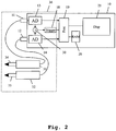
- FIG. 2 the structure and operation of an embodiment of the measuring device according to the invention is illustrated.
- Fig. 3 the operation of an embodiment of the measuring method according to the invention is shown. Identical elements have not been repeated and described in similar illustrations.
- Fig. 1 shows an exemplary meter.
- a differential probe 13 with the two measuring tips 14, 15 is connected via a first terminal 11 to a housing 10.
- the meter has a second terminal 12.
- the meter has two analog-to-digital converters 16, 17.
- the first analog-to-digital converter 16 is associated with the first terminal 11 and connected thereto.
- the second analog-to-digital converter 17 is connected to the second terminal 12.
- a trigger device 18 is connected via a switch optionally to the first analog-to-digital converter 16 or to the second analog-to-digital converter 17.
- the analog-to-digital converter 16, 17 and the trigger device 18 are connected to a processing device 19.
- the processing device 19 is furthermore connected to a memory 20 and a display device 21.
- the measuring tips 14, 15 of the differential probe 13 are subjected to a differential signal.
- the differential probe 13 transmits the analog differential signal to the terminal 11. From there it passes to the first analog-to-digital converter 16. This digitizes the signal and conducts it in the switch position shown to the trigger device 18 and to the processing device 19th further.
- the trigger device 18 performs a triggering of the digitized signal.
- the trigger device 18 is controlled by the processing device 19.
- the processing device 19 processes the triggered digitized differential signal and stores it in the memory 20. In addition, it represents the signal on the display device 21.
- a disadvantage of this exemplary measuring device is that a differential probe is expensive to produce.
- Another disadvantage is that the two sub-signals, from which the differential signal is composed, can not be processed separately from each other. If, for example, disturbances occur in one of the two sub-signals, they can not be localized. For example, if there is a strong noise in one of the two sub-signals, a reliable triggering by the trigger device is not possible and further processing of the entire differential signal is impossible.
- Fig. 2 shows an embodiment of the measuring device according to the invention.
- Two conventional probes 31, 32 each have a measuring tip 34, 35.
- the first probe 31 is connected to a first terminal 11.
- the second probe 32 is connected to a second terminal 12.
- the terminals 11, 12 are arranged on a housing 10.
- the first terminal 11 is connected to an analog-to-digital converter 13.
- the second terminal 12 is connected to a second analog-to-digital converter 14.
- the two analog-to-digital converters 13, 14 are connected to a signal adder 30. Furthermore, they are connected to a processing device 19.
- the signal adder 30 is further connected to a trigger device 18.
- the trigger device 18 is also connected to the processing device 19.
- the analog-to-digital converters 13, 14 of the signal adder 30, the trigger device 18 and the probes 31, 32 together form a real-time section 36 of the measuring device. This means that these components work without caching and process the incoming signals with the speed of the signal input.
- the processing device 19 is also connected to a memory 20 and a display device 21.
- a differential signal is picked up by the two probes 21, 32.
- a first partial signal of the differential signal is received by the first probe 31 by means of the measuring tip 34.
- a second partial signal of the differential signal is received by the second probe 32 by means of the measuring tip 35.
- the sub-signals of the differential signal are supplied via the terminals 11, 12 to the analog-to-digital converters 13, 14.
- the analog-to-digital converters 13, 14 convert the analog partial signals of the differential signal into partial digital signals of the differential signal.
- the digital sub-signals are supplied to the signal adder 30.
- the signal adder 30 adds the signals to a common differential signal and passes it to the trigger device 18.
- the trigger device 18 performs a triggering of the common differential signal. The triggering is controlled by the processing device 19.
- the analog-to-digital converters 13, 14 continue to supply the digital sub-signals of the differential signal to the processing device 19.
- the processing device 19 further processes the sub-signals of the differential signal.
- the processing device 19 forms from the partial signals of the differential signal by addition a differential signal.
- the processing device 19 stores the partial signals or the differential signal in the memory 20 and displays results of the measurements on the display device 21.
- the signal adder 30, the triggering device 18 and the processing device 19 are implemented on an FPGA (Field Programmable Gate Array) or an ASIC (Application Specific Gated Array).
- Fig. 3 shows a first embodiment of the measuring method according to the invention.
- a first step 40 two probes are each subjected to a partial signal of a differential signal. This is usually done by connecting the probes to a DUT.
- the two partial signals of the differential signal are recorded by means of the two probes.
- the recorded partial signals of the differential signal are digitized. The digitization takes place at a certain sampling rate.
- the digitized sub-signals are added. The addition takes place in real time. That is, for each sample of digitized subsignals of the differential signal, an added sample is generated. The addition takes place in such a way that the resulting signal is a digital differential signal. If necessary, one of the sub-signals of the differential signal is inverted or instead of a signal adder a signal subtractor is used to subtract one of the two sub-signals from other sub-signals.
- a triggering of the resulting digital differential signal is performed.
- the digitized sub-signals of the differential signal and the addition-produced differential signal are further processed.
- results of the measurement i. Results of further processing from the sixth step, displayed.
- the invention is not limited to the illustrated embodiment. As already mentioned, Different measuring devices can be used. An extension to more than two channels, ie on several differential signals is conceivable. All of the above-described features or features shown in the figures are combinable with each other within the scope of the invention as claimed.
Landscapes
- Physics & Mathematics (AREA)
- General Physics & Mathematics (AREA)
- Measurement Of Current Or Voltage (AREA)
Claims (11)
- Appareil de mesure pour mesurer des signaux différentiels, comprenant une partie-temps réel (36), appareil de mesure
dans lequel la partie-temps réel (36) renferme deux sondes (31, 32), deux convertisseurs analogiques-numériques (13, 14), un additionneur de signaux et/ou un soustracteur de signaux (30) et un dispositif de déclenchement (18),
dans lequel les sondes (31, 32) assurent respectivement l'acquisition d'un signal partiel d'un signal différentiel,
dans lequel les convertisseurs analogiques-numériques (13, 14) convertissent respectivement un signal partiel en un signal partiel numérique,
dans lequel l'additionneur de signaux ou respectivement soustracteur de signaux (30) additionne ou respectivement soustrait les signaux partiels numériques pour former un signal différentiel numérique,
caractérisé
en ce que le dispositif de déclenchement (18) effectue un déclenchement du signal différentiel numérique au regard du signal différentiel numérique. - Appareil de mesure selon la revendication 1,
caractérisé
en ce que l'appareil de mesure renferme un dispositif de traitement (19), et
en ce que le dispositif de traitement (19) traite le signal différentiel et/ou au moins un signal partiel du signal différentiel, et/ou le mémorise dans une mémoire (20) . - Appareil de mesure selon la revendication 1 ou la revendication 2,
caractérisé
en ce que l'additionneur de signaux ou respectivement soustracteur de signaux (30) et/ou le dispositif de déclenchement (18) sont réalisés au moyen d'un FPGA, c'est-à-dire un 'field programmable gate array' (réseau ou circuit logique programmable), ou d'un ASIC, c'est-à-dire un 'application specific gated array' (circuit intégré propre à une application). - Appareil de mesure selon l'une des revendications 1 à 3,
caractérisé
en ce que les sondes (31, 32) renferment respectivement exactement un raccord de branchement de signal et un raccord de branchement de masse. - Appareil de mesure selon l'une des revendications 1 à 4,
caractérisé
en ce que l'appareil de mesure dispose d'un dispositif de visualisation (21) et en ce que le dispositif de visualisation (21) affiche des résultats de mesures ayant été effectuées. - Appareil de mesure selon l'une des revendications 1 à 5,
caractérisé
en ce que la partie-temps réel (36) traite les signaux entrants avec un taux d'échantillonnage des convertisseurs analogiques-numériques (13, 14). - Procédé de mesure pour mesurer des signaux différentiels, d'après lequel deux sondes (31, 32) assurent respectivement l'acquisition d'un signal partiel d'un signal différentiel, d'après lequel deux convertisseurs analogiques-numériques (13, 14) convertissent respectivement un signal partiel en un signal partiel numérique, et d'après lequel les signaux partiels numériques sont additionnés ou soustraits en un signal différentiel numérique,
caractérisé
en ce que le déclenchement du signal différentiel numérique est effectué au regard du signal différentiel numérique, l'addition ou respectivement la soustraction et le déclenchement étant effectués selon une vitesse d'acquisition des signaux partiels, sans mémorisation intermédiaire. - Procédé de mesure selon la revendication 7,
caractérisé
en ce que le signal différentiel et/ou au moins un signal partiel du signal différentiel sont traités et/ou mémorisés. - Procédé de mesure selon la revendication 7 ou la revendication 8,
caractérisé
en ce que l'addition ou respectivement la soustraction et/ou le déclenchement sont effectués par un FPGA, c'est-à-dire un 'field programmable gate array' (réseau ou circuit logique programmable), ou par un ASIC, c'est-à-dire un 'application specific gated array' (circuit intégré propre à une application). - Procédé de mesure selon l'une des revendications 7 à 9,
caractérisé
en ce que les sondes assurent respectivement l'acquisition d'exactement un signal. - Procédé de mesure selon l'une des revendications 7 à 10,
caractérisé
en ce que des résultats de mesures ayant été effectuées sont affichés par un dispositif de visualisation (21).
Priority Applications (1)
| Application Number | Priority Date | Filing Date | Title |
|---|---|---|---|
| EP18159668.5A EP3349021B8 (fr) | 2009-04-27 | 2010-01-25 | Appareil de mesure et procédé de mesure destinés à mesurer des signaux différentiels |
Applications Claiming Priority (2)
| Application Number | Priority Date | Filing Date | Title |
|---|---|---|---|
| DE102009019039A DE102009019039A1 (de) | 2009-04-27 | 2009-04-27 | Messgerät und Messverfahren zur Messung differentieller Signale |
| PCT/EP2010/000415 WO2010124752A1 (fr) | 2009-04-27 | 2010-01-25 | Appareil de mesure et procédé de mesure pour la mesure de signaux différentiels |
Related Child Applications (1)
| Application Number | Title | Priority Date | Filing Date |
|---|---|---|---|
| EP18159668.5A Division EP3349021B8 (fr) | 2009-04-27 | 2010-01-25 | Appareil de mesure et procédé de mesure destinés à mesurer des signaux différentiels |
Publications (2)
| Publication Number | Publication Date |
|---|---|
| EP2425263A1 EP2425263A1 (fr) | 2012-03-07 |
| EP2425263B1 true EP2425263B1 (fr) | 2018-03-14 |
Family
ID=42104372
Family Applications (2)
| Application Number | Title | Priority Date | Filing Date |
|---|---|---|---|
| EP18159668.5A Active EP3349021B8 (fr) | 2009-04-27 | 2010-01-25 | Appareil de mesure et procédé de mesure destinés à mesurer des signaux différentiels |
| EP10704898.5A Active EP2425263B1 (fr) | 2009-04-27 | 2010-01-25 | Appareil de mesure et procédé de mesure pour la mesure de signaux différentiels |
Family Applications Before (1)
| Application Number | Title | Priority Date | Filing Date |
|---|---|---|---|
| EP18159668.5A Active EP3349021B8 (fr) | 2009-04-27 | 2010-01-25 | Appareil de mesure et procédé de mesure destinés à mesurer des signaux différentiels |
Country Status (4)
| Country | Link |
|---|---|
| US (1) | US8952681B2 (fr) |
| EP (2) | EP3349021B8 (fr) |
| DE (1) | DE102009019039A1 (fr) |
| WO (1) | WO2010124752A1 (fr) |
Families Citing this family (3)
| Publication number | Priority date | Publication date | Assignee | Title |
|---|---|---|---|---|
| DE102014203730A1 (de) * | 2014-02-28 | 2015-09-03 | Rohde & Schwarz Gmbh & Co. Kg | System aus Tastkopf und Messgerät |
| US10060981B2 (en) | 2014-12-03 | 2018-08-28 | Power ProbeTeK, LLC | Diagnostic circuit test device |
| EP3470854A1 (fr) * | 2017-10-12 | 2019-04-17 | Rohde & Schwarz GmbH & Co. KG | Dispositif de mesure à sonde multiples, système de mesure et procédé |
Family Cites Families (6)
| Publication number | Priority date | Publication date | Assignee | Title |
|---|---|---|---|---|
| US4812746A (en) * | 1983-12-23 | 1989-03-14 | Thales Resources, Inc. | Method of using a waveform to sound pattern converter |
| US6704670B2 (en) * | 2002-04-16 | 2004-03-09 | Agilent Technologies, Inc. | Systems and methods for wideband active probing of devices and circuits in operation |
| US6973407B1 (en) | 2004-05-13 | 2005-12-06 | Lsi Logic Corporation | Method and system for capturing data to create Serial ATA eye diagram |
| DE102004029941B3 (de) * | 2004-06-21 | 2005-12-15 | Infineon Technologies Ag | System zur Auswertung eines Sensorsignals |
| DE102005035473A1 (de) * | 2005-07-28 | 2007-02-01 | Rohde & Schwarz Gmbh & Co. Kg | Verfahren und System zur digitalen Triggerung für Oszilloskope |
| DE102005061683B4 (de) * | 2005-12-21 | 2011-12-08 | Forschungsverbund Berlin E.V. | Vorrichtung, Tastkopf und Verfahren zur galvanisch entkoppelten Übertragung eines Messsignals |
-
2009
- 2009-04-27 DE DE102009019039A patent/DE102009019039A1/de not_active Withdrawn
-
2010
- 2010-01-25 EP EP18159668.5A patent/EP3349021B8/fr active Active
- 2010-01-25 EP EP10704898.5A patent/EP2425263B1/fr active Active
- 2010-01-25 US US13/266,705 patent/US8952681B2/en active Active
- 2010-01-25 WO PCT/EP2010/000415 patent/WO2010124752A1/fr not_active Ceased
Also Published As
| Publication number | Publication date |
|---|---|
| WO2010124752A1 (fr) | 2010-11-04 |
| US20120119726A1 (en) | 2012-05-17 |
| WO2010124752A8 (fr) | 2011-04-21 |
| DE102009019039A1 (de) | 2010-11-11 |
| EP2425263A1 (fr) | 2012-03-07 |
| US8952681B2 (en) | 2015-02-10 |
| EP3349021A1 (fr) | 2018-07-18 |
| EP3349021B8 (fr) | 2019-02-27 |
| EP3349021B1 (fr) | 2018-12-12 |
Similar Documents
| Publication | Publication Date | Title |
|---|---|---|
| EP2215484B1 (fr) | Palpeur pour mesurer très précisément une tension continue | |
| EP3349021B1 (fr) | Appareil de mesure et procédé de mesure destinés à mesurer des signaux différentiels | |
| DE102022110953A1 (de) | Echt-äquivalenz-zeit-oszilloskop mit zeitbereichs-reflectometer | |
| DE102012215586A1 (de) | Verringern von Metastabiliät bei einer Analog-Digital-Wandlung | |
| DE112018003599T5 (de) | Systeme, vorrichtungen und verfahren zur messung von gleichstrom-/niederfrequenzsignalkomponenten priorität | |
| EP2721422B1 (fr) | Procédé et appareil de mesure pour la suppression de signaux parasites | |
| DE102021127129B4 (de) | Vorrichtung und Verfahren zur Erfassung eines elektrischen Leitungsstromes mit optimierter Abtastrate | |
| EP4419926A1 (fr) | Dispositif et procédé de détection d'un courant électrique avec fréquence d'échantillonnage optimisée | |
| EP3948312B1 (fr) | Dispositif et procédé de détermination d'une tension de cellule électrique d'un élément de batterie d'une batterie de traction d'un véhicule | |
| DE102022121230A1 (de) | Parallele triggerpfade in einem test- und messinstrument | |
| EP0919819B1 (fr) | Procédé et appareil pour evaluation des signaux de mesure | |
| DE102021127122B4 (de) | Vorrichtung und Verfahren zur Erfassung eines elektrischen Leitungsstromes mit optimierter Abtastrate | |
| DE102016215052A1 (de) | Bandbreitenerweiterung einer Teilentladungsdetektion durch Aliasing des Eingangssignals | |
| DE102021127119B4 (de) | Vorrichtung und Verfahren zur Erfassung eines elektrischen Leitungsstromes mit optimierter Abtastrate | |
| DE102025145304A1 (de) | Mehrkanal-signal- und leistungsanalysator | |
| DE102010046098A1 (de) | Messvorrichtung mit einer Triggereinheit | |
| AT406435B (de) | Verfahren zur ermittlung des leitungszustandes einer übertragungsleitung und schaltungsanordnung zur durchführung des verfahrens | |
| DE112024001823T5 (de) | Verschachtelte digitale trigger-korrektur | |
| DE102013221394A1 (de) | Messgerät und Verfahren zur Messung eines Hochfrequenzsignals mit Deembedding | |
| DE102014203730A1 (de) | System aus Tastkopf und Messgerät | |
| DE102021127131A1 (de) | Vorrichtung und Verfahren zur Erfassung eines elektrischen Leitungsstromes mit optimierter Abtastrate | |
| DE102006037221A1 (de) | Vorrichtung und Verfahren zur Verarbeitung und Darstellung eines abgetasteten Signals | |
| DE102008038690A1 (de) | Vorrichtung und Verfahren zur Maschinendiagnostik mittels Schwingungsmessung | |
| DE102021127121A1 (de) | Vorrichtung und Verfahren zur Erfassung eines elektrischen Leitungsstromes mit optimierter Abtastrate | |
| DE4025332C2 (de) | Verfahren zum Testen von Hochfrequenzgeräten und Testsignalgenerator zum Ausführen dieses Verfahrens |
Legal Events
| Date | Code | Title | Description |
|---|---|---|---|
| PUAI | Public reference made under article 153(3) epc to a published international application that has entered the european phase |
Free format text: ORIGINAL CODE: 0009012 |
|
| 17P | Request for examination filed |
Effective date: 20110915 |
|
| AK | Designated contracting states |
Kind code of ref document: A1 Designated state(s): AT BE BG CH CY CZ DE DK EE ES FI FR GB GR HR HU IE IS IT LI LT LU LV MC MK MT NL NO PL PT RO SE SI SK SM TR |
|
| DAX | Request for extension of the european patent (deleted) | ||
| REG | Reference to a national code |
Ref country code: DE Ref legal event code: R079 Ref document number: 502010014752 Country of ref document: DE Free format text: PREVIOUS MAIN CLASS: G01R0013020000 Ipc: G01R0001067000 |
|
| GRAP | Despatch of communication of intention to grant a patent |
Free format text: ORIGINAL CODE: EPIDOSNIGR1 |
|
| STAA | Information on the status of an ep patent application or granted ep patent |
Free format text: STATUS: GRANT OF PATENT IS INTENDED |
|
| RIC1 | Information provided on ipc code assigned before grant |
Ipc: G01R 1/067 20060101AFI20171020BHEP Ipc: G01R 13/02 20060101ALI20171020BHEP |
|
| INTG | Intention to grant announced |
Effective date: 20171110 |
|
| GRAS | Grant fee paid |
Free format text: ORIGINAL CODE: EPIDOSNIGR3 |
|
| GRAA | (expected) grant |
Free format text: ORIGINAL CODE: 0009210 |
|
| STAA | Information on the status of an ep patent application or granted ep patent |
Free format text: STATUS: THE PATENT HAS BEEN GRANTED |
|
| AK | Designated contracting states |
Kind code of ref document: B1 Designated state(s): AT BE BG CH CY CZ DE DK EE ES FI FR GB GR HR HU IE IS IT LI LT LU LV MC MK MT NL NO PL PT RO SE SI SK SM TR |
|
| REG | Reference to a national code |
Ref country code: GB Ref legal event code: FG4D Free format text: NOT ENGLISH |
|
| REG | Reference to a national code |
Ref country code: CH Ref legal event code: EP Ref country code: AT Ref legal event code: REF Ref document number: 979411 Country of ref document: AT Kind code of ref document: T Effective date: 20180315 |
|
| REG | Reference to a national code |
Ref country code: IE Ref legal event code: FG4D Free format text: LANGUAGE OF EP DOCUMENT: GERMAN |
|
| REG | Reference to a national code |
Ref country code: DE Ref legal event code: R096 Ref document number: 502010014752 Country of ref document: DE |
|
| REG | Reference to a national code |
Ref country code: NL Ref legal event code: MP Effective date: 20180314 |
|
| REG | Reference to a national code |
Ref country code: LT Ref legal event code: MG4D |
|
| PG25 | Lapsed in a contracting state [announced via postgrant information from national office to epo] |
Ref country code: CY Free format text: LAPSE BECAUSE OF FAILURE TO SUBMIT A TRANSLATION OF THE DESCRIPTION OR TO PAY THE FEE WITHIN THE PRESCRIBED TIME-LIMIT Effective date: 20180314 Ref country code: LT Free format text: LAPSE BECAUSE OF FAILURE TO SUBMIT A TRANSLATION OF THE DESCRIPTION OR TO PAY THE FEE WITHIN THE PRESCRIBED TIME-LIMIT Effective date: 20180314 Ref country code: HR Free format text: LAPSE BECAUSE OF FAILURE TO SUBMIT A TRANSLATION OF THE DESCRIPTION OR TO PAY THE FEE WITHIN THE PRESCRIBED TIME-LIMIT Effective date: 20180314 Ref country code: FI Free format text: LAPSE BECAUSE OF FAILURE TO SUBMIT A TRANSLATION OF THE DESCRIPTION OR TO PAY THE FEE WITHIN THE PRESCRIBED TIME-LIMIT Effective date: 20180314 Ref country code: NO Free format text: LAPSE BECAUSE OF FAILURE TO SUBMIT A TRANSLATION OF THE DESCRIPTION OR TO PAY THE FEE WITHIN THE PRESCRIBED TIME-LIMIT Effective date: 20180614 Ref country code: ES Free format text: LAPSE BECAUSE OF FAILURE TO SUBMIT A TRANSLATION OF THE DESCRIPTION OR TO PAY THE FEE WITHIN THE PRESCRIBED TIME-LIMIT Effective date: 20180314 |
|
| PG25 | Lapsed in a contracting state [announced via postgrant information from national office to epo] |
Ref country code: GR Free format text: LAPSE BECAUSE OF FAILURE TO SUBMIT A TRANSLATION OF THE DESCRIPTION OR TO PAY THE FEE WITHIN THE PRESCRIBED TIME-LIMIT Effective date: 20180615 Ref country code: LV Free format text: LAPSE BECAUSE OF FAILURE TO SUBMIT A TRANSLATION OF THE DESCRIPTION OR TO PAY THE FEE WITHIN THE PRESCRIBED TIME-LIMIT Effective date: 20180314 Ref country code: SE Free format text: LAPSE BECAUSE OF FAILURE TO SUBMIT A TRANSLATION OF THE DESCRIPTION OR TO PAY THE FEE WITHIN THE PRESCRIBED TIME-LIMIT Effective date: 20180314 Ref country code: BG Free format text: LAPSE BECAUSE OF FAILURE TO SUBMIT A TRANSLATION OF THE DESCRIPTION OR TO PAY THE FEE WITHIN THE PRESCRIBED TIME-LIMIT Effective date: 20180614 |
|
| PG25 | Lapsed in a contracting state [announced via postgrant information from national office to epo] |
Ref country code: MT Free format text: LAPSE BECAUSE OF FAILURE TO SUBMIT A TRANSLATION OF THE DESCRIPTION OR TO PAY THE FEE WITHIN THE PRESCRIBED TIME-LIMIT Effective date: 20180314 |
|
| PG25 | Lapsed in a contracting state [announced via postgrant information from national office to epo] |
Ref country code: EE Free format text: LAPSE BECAUSE OF FAILURE TO SUBMIT A TRANSLATION OF THE DESCRIPTION OR TO PAY THE FEE WITHIN THE PRESCRIBED TIME-LIMIT Effective date: 20180314 Ref country code: RO Free format text: LAPSE BECAUSE OF FAILURE TO SUBMIT A TRANSLATION OF THE DESCRIPTION OR TO PAY THE FEE WITHIN THE PRESCRIBED TIME-LIMIT Effective date: 20180314 Ref country code: PL Free format text: LAPSE BECAUSE OF FAILURE TO SUBMIT A TRANSLATION OF THE DESCRIPTION OR TO PAY THE FEE WITHIN THE PRESCRIBED TIME-LIMIT Effective date: 20180314 Ref country code: NL Free format text: LAPSE BECAUSE OF FAILURE TO SUBMIT A TRANSLATION OF THE DESCRIPTION OR TO PAY THE FEE WITHIN THE PRESCRIBED TIME-LIMIT Effective date: 20180314 |
|
| PG25 | Lapsed in a contracting state [announced via postgrant information from national office to epo] |
Ref country code: SK Free format text: LAPSE BECAUSE OF FAILURE TO SUBMIT A TRANSLATION OF THE DESCRIPTION OR TO PAY THE FEE WITHIN THE PRESCRIBED TIME-LIMIT Effective date: 20180314 Ref country code: CZ Free format text: LAPSE BECAUSE OF FAILURE TO SUBMIT A TRANSLATION OF THE DESCRIPTION OR TO PAY THE FEE WITHIN THE PRESCRIBED TIME-LIMIT Effective date: 20180314 Ref country code: SM Free format text: LAPSE BECAUSE OF FAILURE TO SUBMIT A TRANSLATION OF THE DESCRIPTION OR TO PAY THE FEE WITHIN THE PRESCRIBED TIME-LIMIT Effective date: 20180314 |
|
| REG | Reference to a national code |
Ref country code: DE Ref legal event code: R097 Ref document number: 502010014752 Country of ref document: DE |
|
| PG25 | Lapsed in a contracting state [announced via postgrant information from national office to epo] |
Ref country code: PT Free format text: LAPSE BECAUSE OF FAILURE TO SUBMIT A TRANSLATION OF THE DESCRIPTION OR TO PAY THE FEE WITHIN THE PRESCRIBED TIME-LIMIT Effective date: 20180716 |
|
| PLBE | No opposition filed within time limit |
Free format text: ORIGINAL CODE: 0009261 |
|
| STAA | Information on the status of an ep patent application or granted ep patent |
Free format text: STATUS: NO OPPOSITION FILED WITHIN TIME LIMIT |
|
| PG25 | Lapsed in a contracting state [announced via postgrant information from national office to epo] |
Ref country code: DK Free format text: LAPSE BECAUSE OF FAILURE TO SUBMIT A TRANSLATION OF THE DESCRIPTION OR TO PAY THE FEE WITHIN THE PRESCRIBED TIME-LIMIT Effective date: 20180314 |
|
| 26N | No opposition filed |
Effective date: 20181217 |
|
| PG25 | Lapsed in a contracting state [announced via postgrant information from national office to epo] |
Ref country code: SI Free format text: LAPSE BECAUSE OF FAILURE TO SUBMIT A TRANSLATION OF THE DESCRIPTION OR TO PAY THE FEE WITHIN THE PRESCRIBED TIME-LIMIT Effective date: 20180314 Ref country code: IT Free format text: LAPSE BECAUSE OF FAILURE TO SUBMIT A TRANSLATION OF THE DESCRIPTION OR TO PAY THE FEE WITHIN THE PRESCRIBED TIME-LIMIT Effective date: 20180314 |
|
| PG25 | Lapsed in a contracting state [announced via postgrant information from national office to epo] |
Ref country code: MC Free format text: LAPSE BECAUSE OF FAILURE TO SUBMIT A TRANSLATION OF THE DESCRIPTION OR TO PAY THE FEE WITHIN THE PRESCRIBED TIME-LIMIT Effective date: 20180314 |
|
| REG | Reference to a national code |
Ref country code: CH Ref legal event code: PL |
|
| PG25 | Lapsed in a contracting state [announced via postgrant information from national office to epo] |
Ref country code: LU Free format text: LAPSE BECAUSE OF NON-PAYMENT OF DUE FEES Effective date: 20190125 |
|
| REG | Reference to a national code |
Ref country code: BE Ref legal event code: MM Effective date: 20190131 |
|
| REG | Reference to a national code |
Ref country code: IE Ref legal event code: MM4A |
|
| PG25 | Lapsed in a contracting state [announced via postgrant information from national office to epo] |
Ref country code: BE Free format text: LAPSE BECAUSE OF NON-PAYMENT OF DUE FEES Effective date: 20190131 |
|
| PG25 | Lapsed in a contracting state [announced via postgrant information from national office to epo] |
Ref country code: CH Free format text: LAPSE BECAUSE OF NON-PAYMENT OF DUE FEES Effective date: 20190131 Ref country code: LI Free format text: LAPSE BECAUSE OF NON-PAYMENT OF DUE FEES Effective date: 20190131 |
|
| PG25 | Lapsed in a contracting state [announced via postgrant information from national office to epo] |
Ref country code: IE Free format text: LAPSE BECAUSE OF NON-PAYMENT OF DUE FEES Effective date: 20190125 |
|
| REG | Reference to a national code |
Ref country code: AT Ref legal event code: MM01 Ref document number: 979411 Country of ref document: AT Kind code of ref document: T Effective date: 20190125 |
|
| PG25 | Lapsed in a contracting state [announced via postgrant information from national office to epo] |
Ref country code: TR Free format text: LAPSE BECAUSE OF FAILURE TO SUBMIT A TRANSLATION OF THE DESCRIPTION OR TO PAY THE FEE WITHIN THE PRESCRIBED TIME-LIMIT Effective date: 20180314 |
|
| PG25 | Lapsed in a contracting state [announced via postgrant information from national office to epo] |
Ref country code: AT Free format text: LAPSE BECAUSE OF NON-PAYMENT OF DUE FEES Effective date: 20190125 |
|
| PG25 | Lapsed in a contracting state [announced via postgrant information from national office to epo] |
Ref country code: IS Free format text: LAPSE BECAUSE OF FAILURE TO SUBMIT A TRANSLATION OF THE DESCRIPTION OR TO PAY THE FEE WITHIN THE PRESCRIBED TIME-LIMIT Effective date: 20180714 |
|
| PG25 | Lapsed in a contracting state [announced via postgrant information from national office to epo] |
Ref country code: HU Free format text: LAPSE BECAUSE OF FAILURE TO SUBMIT A TRANSLATION OF THE DESCRIPTION OR TO PAY THE FEE WITHIN THE PRESCRIBED TIME-LIMIT; INVALID AB INITIO Effective date: 20100125 |
|
| PG25 | Lapsed in a contracting state [announced via postgrant information from national office to epo] |
Ref country code: MK Free format text: LAPSE BECAUSE OF FAILURE TO SUBMIT A TRANSLATION OF THE DESCRIPTION OR TO PAY THE FEE WITHIN THE PRESCRIBED TIME-LIMIT Effective date: 20180314 |
|
| P01 | Opt-out of the competence of the unified patent court (upc) registered |
Effective date: 20230525 |
|
| PGFP | Annual fee paid to national office [announced via postgrant information from national office to epo] |
Ref country code: GB Payment date: 20260122 Year of fee payment: 17 |
|
| PGFP | Annual fee paid to national office [announced via postgrant information from national office to epo] |
Ref country code: DE Payment date: 20260120 Year of fee payment: 17 |
|
| PGFP | Annual fee paid to national office [announced via postgrant information from national office to epo] |
Ref country code: FR Payment date: 20260121 Year of fee payment: 17 |