EP2425263B1 - Measuring device and measuring method for measuring differential signals - Google Patents
Measuring device and measuring method for measuring differential signals Download PDFInfo
- Publication number
- EP2425263B1 EP2425263B1 EP10704898.5A EP10704898A EP2425263B1 EP 2425263 B1 EP2425263 B1 EP 2425263B1 EP 10704898 A EP10704898 A EP 10704898A EP 2425263 B1 EP2425263 B1 EP 2425263B1
- Authority
- EP
- European Patent Office
- Prior art keywords
- signal
- digital
- measuring
- differential signal
- differential
- Prior art date
- Legal status (The legal status is an assumption and is not a legal conclusion. Google has not performed a legal analysis and makes no representation as to the accuracy of the status listed.)
- Active
Links
Images


Classifications
-
- G—PHYSICS
- G01—MEASURING; TESTING
- G01R—MEASURING ELECTRIC VARIABLES; MEASURING MAGNETIC VARIABLES
- G01R13/00—Arrangements for displaying electric variables or waveforms
- G01R13/02—Arrangements for displaying electric variables or waveforms for displaying measured electric variables in digital form
- G01R13/0218—Circuits therefor
- G01R13/0254—Circuits therefor for triggering, synchronisation
-
- G—PHYSICS
- G01—MEASURING; TESTING
- G01R—MEASURING ELECTRIC VARIABLES; MEASURING MAGNETIC VARIABLES
- G01R1/00—Details of instruments or arrangements of the types included in groups G01R5/00 - G01R13/00 and G01R31/00
- G01R1/02—General constructional details
- G01R1/06—Measuring leads; Measuring probes
- G01R1/067—Measuring probes
- G01R1/06766—Input circuits therefor
Definitions
- the invention relates to a measuring device and a measuring method for measuring differential signals, in particular for measuring a differential signal without the use of a differential probe.
- differential signals can not be measured without limitations.
- each with a measuring tip on two different channels of the oscilloscope triggering can be performed only for one of the two received signals.
- triggering is not always successful.
- a triggering on only a partial signal is often not possible.
- differential probes To improve the measurement of differential signals, the use of differential probes is known.
- a probe has two measuring tips for the two sub-signals of the differential signal.
- the differential probe is connected to a single channel of an oscilloscope. The entire differential signal is measured via this one channel of the oscilloscope. Triggering is not a problem here.
- An inventive measuring device for measuring differential signals has a real-time section which contains two probes, a signal adder or signal subtractor and a trigger device.
- the probes each receive a sub-signal of a differential signal.
- the signal adder or signal subtracter adds or subtracts the partial signals to form a differential signal.
- the triggering device carries out a triggering on the basis of the differential signal. This ensures safe triggering.
- the real-time section preferably includes two analog-to-digital converters.
- the analog-to-digital converters preferably digitize the recorded partial signals.
- the signal adder or signal subtractor preferably adds or subtracts the digital sub-signals digitally. So an accurate addition is guaranteed.
- the measuring device preferably includes a processing device.
- the processing device advantageously processes and / or stores the differential signal and / or at least a partial signal of the differential signal. So a detailed analysis of the differential signal is possible.
- the signal adder or signal subtractor and / or the trigger device are realized by means of an FPGA (Field Programmable Gate Array) or an ASIC (Application Specific Gated Array).
- FPGA Field Programmable Gate Array
- ASIC Application Specific Gated Array
- the probes preferably each contain exactly one signal connection and one ground connection. So cheap, easily available probes can be used.
- the measuring device preferably has a display device.
- the display device advantageously displays results of measurements carried out.
- the results of the measurements can be obtained without further equipment, e.g. an external screen.
- the real-time section preferably processes incoming signals at a sampling rate of the analog-to-digital converters without storing them. This achieves reliable triggering.
- FIG. 1 the problem underlying the inventive measuring device and the measuring method according to the invention is explained with reference to an exemplary measuring device.
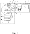
- FIG. 2 the structure and operation of an embodiment of the measuring device according to the invention is illustrated.
- Fig. 3 the operation of an embodiment of the measuring method according to the invention is shown. Identical elements have not been repeated and described in similar illustrations.
- Fig. 1 shows an exemplary meter.
- a differential probe 13 with the two measuring tips 14, 15 is connected via a first terminal 11 to a housing 10.
- the meter has a second terminal 12.
- the meter has two analog-to-digital converters 16, 17.
- the first analog-to-digital converter 16 is associated with the first terminal 11 and connected thereto.
- the second analog-to-digital converter 17 is connected to the second terminal 12.
- a trigger device 18 is connected via a switch optionally to the first analog-to-digital converter 16 or to the second analog-to-digital converter 17.
- the analog-to-digital converter 16, 17 and the trigger device 18 are connected to a processing device 19.
- the processing device 19 is furthermore connected to a memory 20 and a display device 21.
- the measuring tips 14, 15 of the differential probe 13 are subjected to a differential signal.
- the differential probe 13 transmits the analog differential signal to the terminal 11. From there it passes to the first analog-to-digital converter 16. This digitizes the signal and conducts it in the switch position shown to the trigger device 18 and to the processing device 19th further.
- the trigger device 18 performs a triggering of the digitized signal.
- the trigger device 18 is controlled by the processing device 19.
- the processing device 19 processes the triggered digitized differential signal and stores it in the memory 20. In addition, it represents the signal on the display device 21.
- a disadvantage of this exemplary measuring device is that a differential probe is expensive to produce.
- Another disadvantage is that the two sub-signals, from which the differential signal is composed, can not be processed separately from each other. If, for example, disturbances occur in one of the two sub-signals, they can not be localized. For example, if there is a strong noise in one of the two sub-signals, a reliable triggering by the trigger device is not possible and further processing of the entire differential signal is impossible.
- Fig. 2 shows an embodiment of the measuring device according to the invention.
- Two conventional probes 31, 32 each have a measuring tip 34, 35.
- the first probe 31 is connected to a first terminal 11.
- the second probe 32 is connected to a second terminal 12.
- the terminals 11, 12 are arranged on a housing 10.
- the first terminal 11 is connected to an analog-to-digital converter 13.
- the second terminal 12 is connected to a second analog-to-digital converter 14.
- the two analog-to-digital converters 13, 14 are connected to a signal adder 30. Furthermore, they are connected to a processing device 19.
- the signal adder 30 is further connected to a trigger device 18.
- the trigger device 18 is also connected to the processing device 19.
- the analog-to-digital converters 13, 14 of the signal adder 30, the trigger device 18 and the probes 31, 32 together form a real-time section 36 of the measuring device. This means that these components work without caching and process the incoming signals with the speed of the signal input.
- the processing device 19 is also connected to a memory 20 and a display device 21.
- a differential signal is picked up by the two probes 21, 32.
- a first partial signal of the differential signal is received by the first probe 31 by means of the measuring tip 34.
- a second partial signal of the differential signal is received by the second probe 32 by means of the measuring tip 35.
- the sub-signals of the differential signal are supplied via the terminals 11, 12 to the analog-to-digital converters 13, 14.
- the analog-to-digital converters 13, 14 convert the analog partial signals of the differential signal into partial digital signals of the differential signal.
- the digital sub-signals are supplied to the signal adder 30.
- the signal adder 30 adds the signals to a common differential signal and passes it to the trigger device 18.
- the trigger device 18 performs a triggering of the common differential signal. The triggering is controlled by the processing device 19.
- the analog-to-digital converters 13, 14 continue to supply the digital sub-signals of the differential signal to the processing device 19.
- the processing device 19 further processes the sub-signals of the differential signal.
- the processing device 19 forms from the partial signals of the differential signal by addition a differential signal.
- the processing device 19 stores the partial signals or the differential signal in the memory 20 and displays results of the measurements on the display device 21.
- the signal adder 30, the triggering device 18 and the processing device 19 are implemented on an FPGA (Field Programmable Gate Array) or an ASIC (Application Specific Gated Array).
- Fig. 3 shows a first embodiment of the measuring method according to the invention.
- a first step 40 two probes are each subjected to a partial signal of a differential signal. This is usually done by connecting the probes to a DUT.
- the two partial signals of the differential signal are recorded by means of the two probes.
- the recorded partial signals of the differential signal are digitized. The digitization takes place at a certain sampling rate.
- the digitized sub-signals are added. The addition takes place in real time. That is, for each sample of digitized subsignals of the differential signal, an added sample is generated. The addition takes place in such a way that the resulting signal is a digital differential signal. If necessary, one of the sub-signals of the differential signal is inverted or instead of a signal adder a signal subtractor is used to subtract one of the two sub-signals from other sub-signals.
- a triggering of the resulting digital differential signal is performed.
- the digitized sub-signals of the differential signal and the addition-produced differential signal are further processed.
- results of the measurement i. Results of further processing from the sixth step, displayed.
- the invention is not limited to the illustrated embodiment. As already mentioned, Different measuring devices can be used. An extension to more than two channels, ie on several differential signals is conceivable. All of the above-described features or features shown in the figures are combinable with each other within the scope of the invention as claimed.
Landscapes
- Physics & Mathematics (AREA)
- General Physics & Mathematics (AREA)
- Measurement Of Current Or Voltage (AREA)
Description
Die Erfindung betrifft ein Messgerät und ein Messverfahren zur Messung differentieller Signale, insbesondere zur Messung eines differentiellen Signals ohne Anwendung eines differentiellen Tastkopfs.The invention relates to a measuring device and a measuring method for measuring differential signals, in particular for measuring a differential signal without the use of a differential probe.
Mit herkömmlichen Oszilloskopen können differenzielle Signale nicht ohne Einschränkungen gemessen werden. Bei Einsatz üblicher Tastköpfe mit jeweils einer Messspitze an zwei unterschiedlichen Kanälen des Oszilloskops kann eine Triggerung lediglich für eines der beiden empfangenen Signale durchgeführt werden. Bei nicht idealen differentiellen Signalen, wie z.B. einem stark verrauschten Teilsignal, ist eine Triggerung nicht immer erfolgreich. Insbesondere jedoch bei differentiellen Signalen, welche mit einem starken, weitgehend identischen Rauschsignal beaufschlagt sind, ist eine Triggerung auf nur ein Teilsignal oftmals nicht möglich.With conventional oscilloscopes, differential signals can not be measured without limitations. When using conventional probes, each with a measuring tip on two different channels of the oscilloscope triggering can be performed only for one of the two received signals. For non-ideal differential signals, e.g. a heavily noisy sub-signal, triggering is not always successful. In particular, however, in differential signals, which are acted upon by a strong, largely identical noise signal, a triggering on only a partial signal is often not possible.
Zur Verbesserung der Messung differentieller Signale ist der Einsatz differentieller Tastköpfe bekannt. Dabei verfügt ein Tastkopf über zwei Messspitzen für die beiden Teilsignale des differentiellen Signals. Der differentielle Tastkopf ist an einen einzelnen Kanal eines Oszilloskops angeschlossen. Das gesamte differentielle Signal wird über diesen einen Kanal des Oszilloskops gemessen. Die Triggerung ist hier unproblematisch.To improve the measurement of differential signals, the use of differential probes is known. In this case, a probe has two measuring tips for the two sub-signals of the differential signal. The differential probe is connected to a single channel of an oscilloscope. The entire differential signal is measured via this one channel of the oscilloscope. Triggering is not a problem here.
So zeigt die
Die Aufgabe wird erfindungsgemäß für das Messgerät durch die Merkmale des unabhängigen Anspruchs 1 und für das Messverfahren durch die Merkmale des unabhängigen Anspruchs 8 gelöst. Vorteilhafte Weiterbildungen sind Gegenstand der hierauf rückbezogenen Unteransprüche.
Ein erfindungsgemäßes Messgerät zur Messung von differentiellen Signalen verfügt über einen Echtzeitabschnitt, welcher zwei Tastköpfe, einen Signaladdierer bzw. Signalsubtrahierer und eine Triggereinrichtung beinhaltet. Die Tastköpfe nehmen jeweils ein Teilsignal eines differentiellen Signals auf. Der Signaladdierer bzw. Signalsubtrahierer addiert bzw. subtrahiert die Teilsignale zu einem differentiellen Signal. Die Triggereinrichtung führt eine Triggerung anhand des differentiellen Signals durch. So ist eine sichere Triggerung gewährleistet.
Der Echtzeitabschnitt beinhaltet bevorzugt zwei Analog-Digital-Wandler. Die Analog-Digital-Wandler digitalisieren bevorzugt die aufgenommenen Teilsignale. Der Signaladdierer bzw. Signalsubtrahierer addiert bzw. subtrahiert bevorzugt die digitalen Teilsignale digital. So ist eine genaue Addition gewährleistet.The object is achieved for the meter by the features of independent claim 1 and for the measuring method by the features of independent claim 8. Advantageous developments are the subject of the dependent claims.
An inventive measuring device for measuring differential signals has a real-time section which contains two probes, a signal adder or signal subtractor and a trigger device. The probes each receive a sub-signal of a differential signal. The signal adder or signal subtracter adds or subtracts the partial signals to form a differential signal. The triggering device carries out a triggering on the basis of the differential signal. This ensures safe triggering.
The real-time section preferably includes two analog-to-digital converters. The analog-to-digital converters preferably digitize the recorded partial signals. The signal adder or signal subtractor preferably adds or subtracts the digital sub-signals digitally. So an accurate addition is guaranteed.
Das Messgerät beinhaltet bevorzugt eine Verarbeitungseinrichtung. Die Verarbeitungseinrichtung verarbeitet und/oder speichert vorteilhafterweise das differentielle Signal und/oder zumindest ein Teilsignal des differentiellen Signals. So ist eine genaue Analyse des differentiellen Signals möglich.The measuring device preferably includes a processing device. The processing device advantageously processes and / or stores the differential signal and / or at least a partial signal of the differential signal. So a detailed analysis of the differential signal is possible.
Vorteilhafterweise sind der Signaladdierer bzw. Signalsubtrahierer und/oder die Triggereinrichtung mittels eines FPGA (field programmable gate array) oder eines ASIC (application specific gated array) realisiert. So kann das erfindungsgemäße Messgerät mit geringem Aufwand entwickelt und hergestellt werden.Advantageously, the signal adder or signal subtractor and / or the trigger device are realized by means of an FPGA (Field Programmable Gate Array) or an ASIC (Application Specific Gated Array). Thus, the measuring device according to the invention can be developed and manufactured with little effort.
Die Tastköpfe beinhalten bevorzugt jeweils genau einen Signalanschluss und einen Masseanschluss. So können günstige, einfach verfügbare Tastköpfe eingesetzt werden.The probes preferably each contain exactly one signal connection and one ground connection. So cheap, easily available probes can be used.
Das Messgerät verfügt bevorzugt über eine Anzeigeeinrichtung. Die Anzeigeeinrichtung zeigt vorteilhafterweise Ergebnisse durchgeführter Messungen an. So können die Ergebnisse der Messungen ohne weitere Geräte, wie z.B. einen externen Bildschirm dargestellt werden.The measuring device preferably has a display device. The display device advantageously displays results of measurements carried out. Thus, the results of the measurements can be obtained without further equipment, e.g. an external screen.
Der Echtzeitabschnitt verarbeitet bevorzugt eingehende Signale mit einer Abtastrate der Analog-Digital-Wandler ohne sie zu speichern. So wird eine zuverlässige Triggerung erreicht.The real-time section preferably processes incoming signals at a sampling rate of the analog-to-digital converters without storing them. This achieves reliable triggering.
Nachfolgend wird die Erfindung anhand der Zeichnung, in der ein vorteilhaftes Ausführungsbeispiel der Erfindung dargestellt ist, beispielhaft beschrieben. In der Zeichnung zeigen:
- Fig. 1
- ein beispielhaftes Messgerät;
- Fig. 2
- ein Ausführungsbeispiel des erfindungsgemäßen Messgeräts, und
- Fig. 3
- ein Ausführungsbeispiel des erfindungsgemäßen Messverfahrens.
- Fig. 1
- an exemplary meter;
- Fig. 2
- an embodiment of the measuring device according to the invention, and
- Fig. 3
- an embodiment of the measuring method according to the invention.
Zunächst wird anhand der
Die Messspitzen 14, 15 des differentiellen Tastkopfs 13 werden mit einem differentiellen Signal beaufschlagt. Der differentielle Tastkopf 13 überträgt das analoge differentielle Signal an den Anschluss 11. Von dort gelangt es zu dem ersten Analog-Digital-Wandler 16. Dieser digitalisiert das Signal und leitet es bei der gezeigten Schalterstellung an die Trigger-Einrichtung 18 und an die Verarbeitungseinrichtung 19 weiter. Die Trigger-Einrichtung 18 führt eine Triggerung des digitalisierten Signals durch. Die Trigger-Einrichtung 18 wird dabei von der Verarbeitungseinrichtung 19 gesteuert. Die Verarbeitungseinrichtung 19 verarbeitet das getriggerte digitalisierte differentielle Signal weiter und speichert es in dem Speicher 20. Darüber hinaus stellt sie das Signal auf der Anzeigeeinrichtung 21 dar.The measuring
Nachteilhaft an diesem beispielhaften Messgerät ist, dass ein differentieller Tastkopf aufwendig in der Herstellung ist. Weiterhin nachteilig ist, dass die beiden Teilsignale, aus welchen das differentielle Signal zusammengesetzt ist, nicht getrennt voneinander verarbeitet werden können. Treten z.B. Störungen in einem der beiden Teilsignale auf, so können diese nicht lokalisiert werden. Liegt z.B. ein starkes Rauschen in einem der beiden Teilsignale vor, so ist eine zuverlässige Triggerung durch die Trigger-Einrichtung nicht möglich und eine weitere Verarbeitung des gesamten differentiellen Signals wird unmöglich.A disadvantage of this exemplary measuring device is that a differential probe is expensive to produce. Another disadvantage is that the two sub-signals, from which the differential signal is composed, can not be processed separately from each other. If, for example, disturbances occur in one of the two sub-signals, they can not be localized. For example, if there is a strong noise in one of the two sub-signals, a reliable triggering by the trigger device is not possible and further processing of the entire differential signal is impossible.
Ein differentielles Signal wird von den beiden Tastköpfen 21, 32 aufgenommen. Dabei wird ein erstes Teilsignal des differentiellen Signals mittels der Messspitze 34 von dem ersten Tastkopf 31 aufgenommen. Ein zweites Teilsignal des differentiellen Signals wird mittels der Messspitze 35 von dem zweiten Tastkopf 32 aufgenommen. Die Teilsignale des differentiellen Signals werden über die Anschlüsse 11, 12 den Analog-Digital-Wandlern 13, 14 zugeführt. Die Analog-Digital-Wandler 13. 14 wandeln die analogen Teilsignale des differentiellen Signals in digitale Teilsignale des differentiellen Signals um. Die digitalen Teilsignale werden dem Signaladdierer 30 zugeführt. Der Signaladdierer 30 addiert die Signale zu einem gemeinsamen differentiellen Signal und leitet es an die Trigger-Einrichtung 18 weiter. Die Trigger-Einrichtung 18 führt eine Triggerung des gemeinsamen differentiellen Signals durch. Die Triggerung wird dabei von der Verarbeitungseinrichtung 19 gesteuert. Die Analog-Digital-Wandler 13, 14 führen die digitalen Teilsignale des differentiellen Signals weiterhin der Verarbeitungseinrichtung 19 zu. Die Verarbeitungseinrichtung 19 verarbeitet die Teilsignale des differentiellen Signals weiter. Optional bildet die Verarbeitungseinrichtung 19 aus den Teilsignalen des differentiellen Signals durch Addition ein differentielles Signal. Die Verarbeitungseinrichtung 19 speichert die Teilsignale, bzw. das differentielle Signal in dem Speicher 20 und stellt Ergebnisse der Messungen auf der Anzeigeeinrichtung 21 dar.A differential signal is picked up by the two
Optional ist der Signaladdierer 30, die Trigger-Einrichtung 18 und die Verarbeitungseinrichtung 19 auf einem FPGA (field programmable gate array) oder einem ASIC (application specific gated array) ausgebildet.Optionally, the
Im Gegensatz zu dem in
In einem fünften Schritt 44 wird eine Triggerung des so entstandenen digitalen differentiellen Signals durchgeführt. In einem sechsten Schritt 45 werden die digitalisierten Teilsignale des differentiellen Signals und das durch Addition entstandene differentielle Signal weiterverarbeitet. In einem siebten Schritt 46 werden Ergebnisse der Messung, d.h. Ergebnisse der Weiterverarbeitung aus dem sechsten Schritt, angezeigt.In a
Die Erfindung ist nicht auf das dargestellte Ausführungsbeispiel beschränkt. Wie bereits erwähnt, können unterschiedliche Messgeräte eingesetzt werden. Auch eine Erweiterung auf mehr als zwei Kanälen, d.h. auf mehreren differentiellen Signale ist denkbar. Alle vorstehend beschriebenen Merkmale oder in den Figuren gezeigten Merkmale sind im Rahmen der Erfindung wie beansprucht beliebig vorteilhaft miteinander kombinierbar.The invention is not limited to the illustrated embodiment. As already mentioned, Different measuring devices can be used. An extension to more than two channels, ie on several differential signals is conceivable. All of the above-described features or features shown in the figures are combinable with each other within the scope of the invention as claimed.
Claims (11)
- Measuring device for measuring differential signals with a real time section (36),
wherein the real time section (36) comprises two probes (31, 32), two analogue-to-digital converters (13, 14), a signal adder and/or signal subtractor (30) and a trigger unit (18),
wherein the probes (31, 32) each receive a part signal of a differential signal,
wherein the analogue-to-digital converters (13, 14) each convert a part signal into a digital part signal,
wherein the signal adder or signal subtractor (30) respectively adds or subtracts the digital part signals to form a digital differential signal,
characterised in that
the trigger unit (18) carries out triggering of the digital differential signal based on the digital differential signal. - Measuring device according to claim 1,
characterised in that
the measuring device comprises a processing unit (19), and
in that the processing unit (19) processes the differential signal and/or at least a part signal of the differential signal and/or stores it in a memory (20). - Measuring device according to claim 1 or 2,
characterised in that
the signal adder or signal subtractor (30) and/or the trigger unit (18) are formed by means of an FPGA, i.e. a field programmable gate array, or an ASIC, i.e. an application specific gated array. - Measuring device according to one of claims 1 to 3,
characterised in that
the probes (31, 32) each comprise just one signal terminal and one ground terminal. - Measuring device according to one of claims 1 to 4,
characterised in that
the measuring device has a display unit (21), and in that the display unit (21) displays results of measurements that have been carried out. - Measuring device according to one of claims 1 to 5,
characterised in that
the real time section (36) processes incoming signals with a sampling rate of the analogue-to-digital converters (13, 14). - Measuring method for measuring differential signals,
wherein a part signal of a differential signal is received by each of two probes (31, 32),
wherein two analogue-to-digital converters (13 ,14) each convert a part signal into a digital part signal, wherein the digital part signals are added or subtracted to form a digital differential signal,
characterised in that
the triggering of the digital differential signal is carried out based on the digital differential signal, wherein the addition or subtraction and the triggering being carried out at a speed of reception of the part signals without intermediate storage. - Measuring method according to claim 7,
characterised in that
the differential signal and/or at least a part signal of the differential signal are processed further and/or stored. - Measuring method according to claim 7 or 8,
characterised in that
the addition or subtraction and/or the triggering are carried out by an FPGA, i.e. a field programmable gate array, or an ASIC, i.e. an application specific gated array. - Measuring method according to one of claims 7 to 9,
characterised in that
the probes each receive just one signal. - Measuring method according to one of claims 7 to 10,
characterised in that
results of measurements that have been carried out are displayed by a display unit (21).
Priority Applications (1)
| Application Number | Priority Date | Filing Date | Title |
|---|---|---|---|
| EP18159668.5A EP3349021B8 (en) | 2009-04-27 | 2010-01-25 | Measuring device and measurement method for measuring differential signals |
Applications Claiming Priority (2)
| Application Number | Priority Date | Filing Date | Title |
|---|---|---|---|
| DE102009019039A DE102009019039A1 (en) | 2009-04-27 | 2009-04-27 | Measuring device and measuring method for measuring differential signals |
| PCT/EP2010/000415 WO2010124752A1 (en) | 2009-04-27 | 2010-01-25 | Measuring machine and measuring method for measuring differential signals |
Related Child Applications (1)
| Application Number | Title | Priority Date | Filing Date |
|---|---|---|---|
| EP18159668.5A Division EP3349021B8 (en) | 2009-04-27 | 2010-01-25 | Measuring device and measurement method for measuring differential signals |
Publications (2)
| Publication Number | Publication Date |
|---|---|
| EP2425263A1 EP2425263A1 (en) | 2012-03-07 |
| EP2425263B1 true EP2425263B1 (en) | 2018-03-14 |
Family
ID=42104372
Family Applications (2)
| Application Number | Title | Priority Date | Filing Date |
|---|---|---|---|
| EP18159668.5A Active EP3349021B8 (en) | 2009-04-27 | 2010-01-25 | Measuring device and measurement method for measuring differential signals |
| EP10704898.5A Active EP2425263B1 (en) | 2009-04-27 | 2010-01-25 | Measuring device and measuring method for measuring differential signals |
Family Applications Before (1)
| Application Number | Title | Priority Date | Filing Date |
|---|---|---|---|
| EP18159668.5A Active EP3349021B8 (en) | 2009-04-27 | 2010-01-25 | Measuring device and measurement method for measuring differential signals |
Country Status (4)
| Country | Link |
|---|---|
| US (1) | US8952681B2 (en) |
| EP (2) | EP3349021B8 (en) |
| DE (1) | DE102009019039A1 (en) |
| WO (1) | WO2010124752A1 (en) |
Families Citing this family (3)
| Publication number | Priority date | Publication date | Assignee | Title |
|---|---|---|---|---|
| DE102014203730A1 (en) * | 2014-02-28 | 2015-09-03 | Rohde & Schwarz Gmbh & Co. Kg | System of probe and measuring device |
| US10060981B2 (en) | 2014-12-03 | 2018-08-28 | Power ProbeTeK, LLC | Diagnostic circuit test device |
| EP3470854A1 (en) * | 2017-10-12 | 2019-04-17 | Rohde & Schwarz GmbH & Co. KG | Multi probe measurement device, measuring system and method |
Family Cites Families (6)
| Publication number | Priority date | Publication date | Assignee | Title |
|---|---|---|---|---|
| US4812746A (en) * | 1983-12-23 | 1989-03-14 | Thales Resources, Inc. | Method of using a waveform to sound pattern converter |
| US6704670B2 (en) * | 2002-04-16 | 2004-03-09 | Agilent Technologies, Inc. | Systems and methods for wideband active probing of devices and circuits in operation |
| US6973407B1 (en) | 2004-05-13 | 2005-12-06 | Lsi Logic Corporation | Method and system for capturing data to create Serial ATA eye diagram |
| DE102004029941B3 (en) * | 2004-06-21 | 2005-12-15 | Infineon Technologies Ag | System for evaluating a sensor signal |
| DE102005035473A1 (en) * | 2005-07-28 | 2007-02-01 | Rohde & Schwarz Gmbh & Co. Kg | Method and system for digital triggering for oscilloscopes |
| DE102005061683B4 (en) * | 2005-12-21 | 2011-12-08 | Forschungsverbund Berlin E.V. | Device, probe and method for the galvanically decoupled transmission of a measurement signal |
-
2009
- 2009-04-27 DE DE102009019039A patent/DE102009019039A1/en not_active Withdrawn
-
2010
- 2010-01-25 EP EP18159668.5A patent/EP3349021B8/en active Active
- 2010-01-25 EP EP10704898.5A patent/EP2425263B1/en active Active
- 2010-01-25 US US13/266,705 patent/US8952681B2/en active Active
- 2010-01-25 WO PCT/EP2010/000415 patent/WO2010124752A1/en not_active Ceased
Also Published As
| Publication number | Publication date |
|---|---|
| WO2010124752A1 (en) | 2010-11-04 |
| US20120119726A1 (en) | 2012-05-17 |
| WO2010124752A8 (en) | 2011-04-21 |
| DE102009019039A1 (en) | 2010-11-11 |
| EP2425263A1 (en) | 2012-03-07 |
| US8952681B2 (en) | 2015-02-10 |
| EP3349021A1 (en) | 2018-07-18 |
| EP3349021B8 (en) | 2019-02-27 |
| EP3349021B1 (en) | 2018-12-12 |
Similar Documents
| Publication | Publication Date | Title |
|---|---|---|
| EP2215484B1 (en) | Probe with highly precise direct current measurement | |
| EP3349021B1 (en) | Measuring device and measurement method for measuring differential signals | |
| DE102022110953A1 (en) | TRUE EQUIVALENCE TIME OSCILLOSCOPE WITH TIME DOMAIN REFLECTOMETER | |
| DE102012215586A1 (en) | Reduce metastability in an analog-to-digital conversion | |
| DE112018003599T5 (en) | SYSTEMS, DEVICES AND METHODS FOR MEASURING DC / LOW-FREQUENCY SIGNAL COMPONENTS PRIORITY | |
| EP2721422B1 (en) | Method and measuring device for suppressing interfering signals | |
| DE102021127129B4 (en) | Device and method for detecting an electrical line current with an optimized sampling rate | |
| EP4419926A1 (en) | Device and method for detecting an electrical current with an optimised sampling rate | |
| EP3948312B1 (en) | Device and method for determining an electrical cell voltage of a battery cell of a traction battery of a vehicle | |
| DE102022121230A1 (en) | PARALLEL TRIGGER PATHS IN A TEST AND MEASUREMENT INSTRUMENT | |
| EP0919819B1 (en) | Procedure and device for evaluating measurement signals | |
| DE102021127122B4 (en) | Device and method for detecting an electrical line current with an optimized sampling rate | |
| DE102016215052A1 (en) | Bandwidth extension of a partial discharge detection by aliasing of the input signal | |
| DE102021127119B4 (en) | Device and method for detecting an electrical line current with an optimized sampling rate | |
| DE102025145304A1 (en) | MULTI-CHANNEL SIGNAL AND POWER ANALYST | |
| DE102010046098A1 (en) | Measuring device with a trigger unit | |
| AT406435B (en) | METHOD FOR DETERMINING THE LINE CONDITION OF A TRANSMISSION LINE AND CIRCUIT ARRANGEMENT FOR IMPLEMENTING THE METHOD | |
| DE112024001823T5 (en) | Nested Digital Trigger Correction | |
| DE102013221394A1 (en) | Measuring device and method for measuring a high-frequency signal with de-embedding | |
| DE102014203730A1 (en) | System of probe and measuring device | |
| DE102021127131A1 (en) | Device and method for detecting an electrical line current with an optimized sampling rate | |
| DE102006037221A1 (en) | Apparatus and method for processing and displaying a sampled signal | |
| DE102008038690A1 (en) | Device and method for machine diagnostics by means of vibration measurement | |
| DE102021127121A1 (en) | Device and method for detecting an electrical line current with an optimized sampling rate | |
| DE4025332C2 (en) | Method for testing high frequency devices and test signal generator for performing this method |
Legal Events
| Date | Code | Title | Description |
|---|---|---|---|
| PUAI | Public reference made under article 153(3) epc to a published international application that has entered the european phase |
Free format text: ORIGINAL CODE: 0009012 |
|
| 17P | Request for examination filed |
Effective date: 20110915 |
|
| AK | Designated contracting states |
Kind code of ref document: A1 Designated state(s): AT BE BG CH CY CZ DE DK EE ES FI FR GB GR HR HU IE IS IT LI LT LU LV MC MK MT NL NO PL PT RO SE SI SK SM TR |
|
| DAX | Request for extension of the european patent (deleted) | ||
| REG | Reference to a national code |
Ref country code: DE Ref legal event code: R079 Ref document number: 502010014752 Country of ref document: DE Free format text: PREVIOUS MAIN CLASS: G01R0013020000 Ipc: G01R0001067000 |
|
| GRAP | Despatch of communication of intention to grant a patent |
Free format text: ORIGINAL CODE: EPIDOSNIGR1 |
|
| STAA | Information on the status of an ep patent application or granted ep patent |
Free format text: STATUS: GRANT OF PATENT IS INTENDED |
|
| RIC1 | Information provided on ipc code assigned before grant |
Ipc: G01R 1/067 20060101AFI20171020BHEP Ipc: G01R 13/02 20060101ALI20171020BHEP |
|
| INTG | Intention to grant announced |
Effective date: 20171110 |
|
| GRAS | Grant fee paid |
Free format text: ORIGINAL CODE: EPIDOSNIGR3 |
|
| GRAA | (expected) grant |
Free format text: ORIGINAL CODE: 0009210 |
|
| STAA | Information on the status of an ep patent application or granted ep patent |
Free format text: STATUS: THE PATENT HAS BEEN GRANTED |
|
| AK | Designated contracting states |
Kind code of ref document: B1 Designated state(s): AT BE BG CH CY CZ DE DK EE ES FI FR GB GR HR HU IE IS IT LI LT LU LV MC MK MT NL NO PL PT RO SE SI SK SM TR |
|
| REG | Reference to a national code |
Ref country code: GB Ref legal event code: FG4D Free format text: NOT ENGLISH |
|
| REG | Reference to a national code |
Ref country code: CH Ref legal event code: EP Ref country code: AT Ref legal event code: REF Ref document number: 979411 Country of ref document: AT Kind code of ref document: T Effective date: 20180315 |
|
| REG | Reference to a national code |
Ref country code: IE Ref legal event code: FG4D Free format text: LANGUAGE OF EP DOCUMENT: GERMAN |
|
| REG | Reference to a national code |
Ref country code: DE Ref legal event code: R096 Ref document number: 502010014752 Country of ref document: DE |
|
| REG | Reference to a national code |
Ref country code: NL Ref legal event code: MP Effective date: 20180314 |
|
| REG | Reference to a national code |
Ref country code: LT Ref legal event code: MG4D |
|
| PG25 | Lapsed in a contracting state [announced via postgrant information from national office to epo] |
Ref country code: CY Free format text: LAPSE BECAUSE OF FAILURE TO SUBMIT A TRANSLATION OF THE DESCRIPTION OR TO PAY THE FEE WITHIN THE PRESCRIBED TIME-LIMIT Effective date: 20180314 Ref country code: LT Free format text: LAPSE BECAUSE OF FAILURE TO SUBMIT A TRANSLATION OF THE DESCRIPTION OR TO PAY THE FEE WITHIN THE PRESCRIBED TIME-LIMIT Effective date: 20180314 Ref country code: HR Free format text: LAPSE BECAUSE OF FAILURE TO SUBMIT A TRANSLATION OF THE DESCRIPTION OR TO PAY THE FEE WITHIN THE PRESCRIBED TIME-LIMIT Effective date: 20180314 Ref country code: FI Free format text: LAPSE BECAUSE OF FAILURE TO SUBMIT A TRANSLATION OF THE DESCRIPTION OR TO PAY THE FEE WITHIN THE PRESCRIBED TIME-LIMIT Effective date: 20180314 Ref country code: NO Free format text: LAPSE BECAUSE OF FAILURE TO SUBMIT A TRANSLATION OF THE DESCRIPTION OR TO PAY THE FEE WITHIN THE PRESCRIBED TIME-LIMIT Effective date: 20180614 Ref country code: ES Free format text: LAPSE BECAUSE OF FAILURE TO SUBMIT A TRANSLATION OF THE DESCRIPTION OR TO PAY THE FEE WITHIN THE PRESCRIBED TIME-LIMIT Effective date: 20180314 |
|
| PG25 | Lapsed in a contracting state [announced via postgrant information from national office to epo] |
Ref country code: GR Free format text: LAPSE BECAUSE OF FAILURE TO SUBMIT A TRANSLATION OF THE DESCRIPTION OR TO PAY THE FEE WITHIN THE PRESCRIBED TIME-LIMIT Effective date: 20180615 Ref country code: LV Free format text: LAPSE BECAUSE OF FAILURE TO SUBMIT A TRANSLATION OF THE DESCRIPTION OR TO PAY THE FEE WITHIN THE PRESCRIBED TIME-LIMIT Effective date: 20180314 Ref country code: SE Free format text: LAPSE BECAUSE OF FAILURE TO SUBMIT A TRANSLATION OF THE DESCRIPTION OR TO PAY THE FEE WITHIN THE PRESCRIBED TIME-LIMIT Effective date: 20180314 Ref country code: BG Free format text: LAPSE BECAUSE OF FAILURE TO SUBMIT A TRANSLATION OF THE DESCRIPTION OR TO PAY THE FEE WITHIN THE PRESCRIBED TIME-LIMIT Effective date: 20180614 |
|
| PG25 | Lapsed in a contracting state [announced via postgrant information from national office to epo] |
Ref country code: MT Free format text: LAPSE BECAUSE OF FAILURE TO SUBMIT A TRANSLATION OF THE DESCRIPTION OR TO PAY THE FEE WITHIN THE PRESCRIBED TIME-LIMIT Effective date: 20180314 |
|
| PG25 | Lapsed in a contracting state [announced via postgrant information from national office to epo] |
Ref country code: EE Free format text: LAPSE BECAUSE OF FAILURE TO SUBMIT A TRANSLATION OF THE DESCRIPTION OR TO PAY THE FEE WITHIN THE PRESCRIBED TIME-LIMIT Effective date: 20180314 Ref country code: RO Free format text: LAPSE BECAUSE OF FAILURE TO SUBMIT A TRANSLATION OF THE DESCRIPTION OR TO PAY THE FEE WITHIN THE PRESCRIBED TIME-LIMIT Effective date: 20180314 Ref country code: PL Free format text: LAPSE BECAUSE OF FAILURE TO SUBMIT A TRANSLATION OF THE DESCRIPTION OR TO PAY THE FEE WITHIN THE PRESCRIBED TIME-LIMIT Effective date: 20180314 Ref country code: NL Free format text: LAPSE BECAUSE OF FAILURE TO SUBMIT A TRANSLATION OF THE DESCRIPTION OR TO PAY THE FEE WITHIN THE PRESCRIBED TIME-LIMIT Effective date: 20180314 |
|
| PG25 | Lapsed in a contracting state [announced via postgrant information from national office to epo] |
Ref country code: SK Free format text: LAPSE BECAUSE OF FAILURE TO SUBMIT A TRANSLATION OF THE DESCRIPTION OR TO PAY THE FEE WITHIN THE PRESCRIBED TIME-LIMIT Effective date: 20180314 Ref country code: CZ Free format text: LAPSE BECAUSE OF FAILURE TO SUBMIT A TRANSLATION OF THE DESCRIPTION OR TO PAY THE FEE WITHIN THE PRESCRIBED TIME-LIMIT Effective date: 20180314 Ref country code: SM Free format text: LAPSE BECAUSE OF FAILURE TO SUBMIT A TRANSLATION OF THE DESCRIPTION OR TO PAY THE FEE WITHIN THE PRESCRIBED TIME-LIMIT Effective date: 20180314 |
|
| REG | Reference to a national code |
Ref country code: DE Ref legal event code: R097 Ref document number: 502010014752 Country of ref document: DE |
|
| PG25 | Lapsed in a contracting state [announced via postgrant information from national office to epo] |
Ref country code: PT Free format text: LAPSE BECAUSE OF FAILURE TO SUBMIT A TRANSLATION OF THE DESCRIPTION OR TO PAY THE FEE WITHIN THE PRESCRIBED TIME-LIMIT Effective date: 20180716 |
|
| PLBE | No opposition filed within time limit |
Free format text: ORIGINAL CODE: 0009261 |
|
| STAA | Information on the status of an ep patent application or granted ep patent |
Free format text: STATUS: NO OPPOSITION FILED WITHIN TIME LIMIT |
|
| PG25 | Lapsed in a contracting state [announced via postgrant information from national office to epo] |
Ref country code: DK Free format text: LAPSE BECAUSE OF FAILURE TO SUBMIT A TRANSLATION OF THE DESCRIPTION OR TO PAY THE FEE WITHIN THE PRESCRIBED TIME-LIMIT Effective date: 20180314 |
|
| 26N | No opposition filed |
Effective date: 20181217 |
|
| PG25 | Lapsed in a contracting state [announced via postgrant information from national office to epo] |
Ref country code: SI Free format text: LAPSE BECAUSE OF FAILURE TO SUBMIT A TRANSLATION OF THE DESCRIPTION OR TO PAY THE FEE WITHIN THE PRESCRIBED TIME-LIMIT Effective date: 20180314 Ref country code: IT Free format text: LAPSE BECAUSE OF FAILURE TO SUBMIT A TRANSLATION OF THE DESCRIPTION OR TO PAY THE FEE WITHIN THE PRESCRIBED TIME-LIMIT Effective date: 20180314 |
|
| PG25 | Lapsed in a contracting state [announced via postgrant information from national office to epo] |
Ref country code: MC Free format text: LAPSE BECAUSE OF FAILURE TO SUBMIT A TRANSLATION OF THE DESCRIPTION OR TO PAY THE FEE WITHIN THE PRESCRIBED TIME-LIMIT Effective date: 20180314 |
|
| REG | Reference to a national code |
Ref country code: CH Ref legal event code: PL |
|
| PG25 | Lapsed in a contracting state [announced via postgrant information from national office to epo] |
Ref country code: LU Free format text: LAPSE BECAUSE OF NON-PAYMENT OF DUE FEES Effective date: 20190125 |
|
| REG | Reference to a national code |
Ref country code: BE Ref legal event code: MM Effective date: 20190131 |
|
| REG | Reference to a national code |
Ref country code: IE Ref legal event code: MM4A |
|
| PG25 | Lapsed in a contracting state [announced via postgrant information from national office to epo] |
Ref country code: BE Free format text: LAPSE BECAUSE OF NON-PAYMENT OF DUE FEES Effective date: 20190131 |
|
| PG25 | Lapsed in a contracting state [announced via postgrant information from national office to epo] |
Ref country code: CH Free format text: LAPSE BECAUSE OF NON-PAYMENT OF DUE FEES Effective date: 20190131 Ref country code: LI Free format text: LAPSE BECAUSE OF NON-PAYMENT OF DUE FEES Effective date: 20190131 |
|
| PG25 | Lapsed in a contracting state [announced via postgrant information from national office to epo] |
Ref country code: IE Free format text: LAPSE BECAUSE OF NON-PAYMENT OF DUE FEES Effective date: 20190125 |
|
| REG | Reference to a national code |
Ref country code: AT Ref legal event code: MM01 Ref document number: 979411 Country of ref document: AT Kind code of ref document: T Effective date: 20190125 |
|
| PG25 | Lapsed in a contracting state [announced via postgrant information from national office to epo] |
Ref country code: TR Free format text: LAPSE BECAUSE OF FAILURE TO SUBMIT A TRANSLATION OF THE DESCRIPTION OR TO PAY THE FEE WITHIN THE PRESCRIBED TIME-LIMIT Effective date: 20180314 |
|
| PG25 | Lapsed in a contracting state [announced via postgrant information from national office to epo] |
Ref country code: AT Free format text: LAPSE BECAUSE OF NON-PAYMENT OF DUE FEES Effective date: 20190125 |
|
| PG25 | Lapsed in a contracting state [announced via postgrant information from national office to epo] |
Ref country code: IS Free format text: LAPSE BECAUSE OF FAILURE TO SUBMIT A TRANSLATION OF THE DESCRIPTION OR TO PAY THE FEE WITHIN THE PRESCRIBED TIME-LIMIT Effective date: 20180714 |
|
| PG25 | Lapsed in a contracting state [announced via postgrant information from national office to epo] |
Ref country code: HU Free format text: LAPSE BECAUSE OF FAILURE TO SUBMIT A TRANSLATION OF THE DESCRIPTION OR TO PAY THE FEE WITHIN THE PRESCRIBED TIME-LIMIT; INVALID AB INITIO Effective date: 20100125 |
|
| PG25 | Lapsed in a contracting state [announced via postgrant information from national office to epo] |
Ref country code: MK Free format text: LAPSE BECAUSE OF FAILURE TO SUBMIT A TRANSLATION OF THE DESCRIPTION OR TO PAY THE FEE WITHIN THE PRESCRIBED TIME-LIMIT Effective date: 20180314 |
|
| P01 | Opt-out of the competence of the unified patent court (upc) registered |
Effective date: 20230525 |
|
| PGFP | Annual fee paid to national office [announced via postgrant information from national office to epo] |
Ref country code: GB Payment date: 20260122 Year of fee payment: 17 |
|
| PGFP | Annual fee paid to national office [announced via postgrant information from national office to epo] |
Ref country code: DE Payment date: 20260120 Year of fee payment: 17 |
|
| PGFP | Annual fee paid to national office [announced via postgrant information from national office to epo] |
Ref country code: FR Payment date: 20260121 Year of fee payment: 17 |