EP2425149B1 - Amortisseur de vibrations - Google Patents
Amortisseur de vibrations Download PDFInfo
- Publication number
- EP2425149B1 EP2425149B1 EP10717512.7A EP10717512A EP2425149B1 EP 2425149 B1 EP2425149 B1 EP 2425149B1 EP 10717512 A EP10717512 A EP 10717512A EP 2425149 B1 EP2425149 B1 EP 2425149B1
- Authority
- EP
- European Patent Office
- Prior art keywords
- vibration damper
- radially
- flywheel
- disc
- drive shaft
- Prior art date
- Legal status (The legal status is an assumption and is not a legal conclusion. Google has not performed a legal analysis and makes no representation as to the accuracy of the status listed.)
- Not-in-force
Links
- 239000000463 material Substances 0.000 claims description 15
- 230000003014 reinforcing effect Effects 0.000 claims description 3
- 230000009471 action Effects 0.000 claims description 2
- 238000004146 energy storage Methods 0.000 description 25
- 238000013459 approach Methods 0.000 description 7
- 238000004080 punching Methods 0.000 description 5
- 230000009977 dual effect Effects 0.000 description 4
- 238000002485 combustion reaction Methods 0.000 description 3
- 238000013461 design Methods 0.000 description 3
- 238000004519 manufacturing process Methods 0.000 description 3
- 239000007858 starting material Substances 0.000 description 3
- 230000015572 biosynthetic process Effects 0.000 description 2
- 238000013016 damping Methods 0.000 description 2
- 238000011161 development Methods 0.000 description 2
- 230000000694 effects Effects 0.000 description 2
- 238000007373 indentation Methods 0.000 description 2
- 238000002955 isolation Methods 0.000 description 2
- 238000000034 method Methods 0.000 description 2
- 230000008569 process Effects 0.000 description 2
- 230000009467 reduction Effects 0.000 description 2
- 238000003860 storage Methods 0.000 description 2
- 238000003466 welding Methods 0.000 description 2
- 229910000831 Steel Inorganic materials 0.000 description 1
- 238000009825 accumulation Methods 0.000 description 1
- 239000011324 bead Substances 0.000 description 1
- 230000002146 bilateral effect Effects 0.000 description 1
- 238000005520 cutting process Methods 0.000 description 1
- 238000011156 evaluation Methods 0.000 description 1
- 210000004907 gland Anatomy 0.000 description 1
- 230000006698 induction Effects 0.000 description 1
- 238000012986 modification Methods 0.000 description 1
- 230000004048 modification Effects 0.000 description 1
- 230000010355 oscillation Effects 0.000 description 1
- 230000035515 penetration Effects 0.000 description 1
- 230000002093 peripheral effect Effects 0.000 description 1
- 230000008707 rearrangement Effects 0.000 description 1
- 230000002787 reinforcement Effects 0.000 description 1
- 238000005096 rolling process Methods 0.000 description 1
- 238000007789 sealing Methods 0.000 description 1
- 238000000926 separation method Methods 0.000 description 1
- 239000010959 steel Substances 0.000 description 1
- 238000010408 sweeping Methods 0.000 description 1
- 239000002699 waste material Substances 0.000 description 1
Images


Classifications
-
- F—MECHANICAL ENGINEERING; LIGHTING; HEATING; WEAPONS; BLASTING
- F16—ENGINEERING ELEMENTS AND UNITS; GENERAL MEASURES FOR PRODUCING AND MAINTAINING EFFECTIVE FUNCTIONING OF MACHINES OR INSTALLATIONS; THERMAL INSULATION IN GENERAL
- F16F—SPRINGS; SHOCK-ABSORBERS; MEANS FOR DAMPING VIBRATION
- F16F15/00—Suppression of vibrations in systems; Means or arrangements for avoiding or reducing out-of-balance forces, e.g. due to motion
- F16F15/10—Suppression of vibrations in rotating systems by making use of members moving with the system
- F16F15/12—Suppression of vibrations in rotating systems by making use of members moving with the system using elastic members or friction-damping members, e.g. between a rotating shaft and a gyratory mass mounted thereon
- F16F15/131—Suppression of vibrations in rotating systems by making use of members moving with the system using elastic members or friction-damping members, e.g. between a rotating shaft and a gyratory mass mounted thereon the rotating system comprising two or more gyratory masses
- F16F15/133—Suppression of vibrations in rotating systems by making use of members moving with the system using elastic members or friction-damping members, e.g. between a rotating shaft and a gyratory mass mounted thereon the rotating system comprising two or more gyratory masses using springs as elastic members, e.g. metallic springs
- F16F15/134—Wound springs
- F16F15/1343—Wound springs characterised by the spring mounting
- F16F15/13453—Additional guiding means for springs
Definitions
- the invention relates to a vibration damper arranged on a drive unit with a drive shaft, with two counter to the effect of several circumferentially arranged energy storage relatively rotatable flywheels, wherein a first of the flywheel masses, an annular chamber for receiving the energy storage forming, interconnected disc parts and a second of the flywheel masses, from radially inward into the annular chamber engaging, acting in the circumferential direction on the energy storage Beaufschlagungs adopteden for energy storage.
- vibration dampers for example dual mass flywheels (ZMS) and dual mass dampers (ZMD) are known in various embodiments of the prior art.
- ZMS dual mass flywheels
- ZMD dual mass dampers
- On the second flywheel an annular flange portion is fixed, which has two radially expanded arms, which are radially expanded in a space between the two disc-forming the annular chamber and form the loading means of the energy storage.
- the formed as a full annular flange portion requires a high material usage and large hardness tools.
- the sprocket such as starter ring gear is centered on an additional mass which is mounted on an annular axial projection of a disc portion forming the annular chamber.
- the object of the invention is the advantageous development of vibration damping in particular against the background of cost-effective production and improved manufacturing quality.
- a vibration damper arranged on a drive unit with a drive shaft, with two counter to the effect of several circumferentially arranged energy storage relatively rotatable flywheels, wherein a first of the flywheel masses, a ring chamber for receiving the energy storage forming, interconnected disc parts and a second one of the flywheel masses has a loading means acting radially inwardly into the annular chamber and acting circumferentially on the energy storage devices, and in each case one loading device of one of a plurality of circumferentially distributed and on the other flywheel mass recorded flange segments is formed.
- a high material saving rate is achieved, since the flange segments can be placed in the case of a punching on the strip material to save material and the punching waste is reduced. Furthermore, the hardened for the at least in the region of the loading areas flange segments smaller sized hardening devices can be used.
- the flange segments are compared to an annular flange easier and geometrically equipped with a greater degree of freedom, so that the arms can be threaded as loading devices in a corresponding design of the vibration before mounting on the second flywheel in the corresponding space situation of the disc parts.
- the second flywheel may for example be made of steel, for example, stamped and / or designed to be correspondingly deforming, wherein the flange segments can be welded, riveted or formed on this formed Nietwarzen with this.
- the flange segments are riveted to it.
- the flange segments are essentially designed such that per flange part a radially opposite in both circumferential directions aligned wings or tabs for attachment of the flange segment on the second flywheel extended arm with the peripheral loading means as Beaufschlagungs vom is provided.
- the loading devices can each pass radially into a substantially axially aligned region of a disk part provided recesses of the first flywheel, which may be closed or designed as unilaterally open Axialprofiltechniken.
- a loading device can be threaded into a respective recess before the associated flange segment is attached to the second flywheel.
- at least one disc member has axial portions on both sides of the flange segments.
- a first disc part received on the drive shaft of the drive unit can be axially cranked in the region of the recesses.
- a disk part formed in this way can have, radially on the outside, a preferably axial axial projection formed in the direction of the second flywheel, for example, on which a sprocket such as a starter ring gear can be accommodated centered.
- a vibration damper for example a dual mass flywheel or dual mass damper with flange segments and disk parts of the first Flywheels
- the sprocket is supported on that disc part, which simultaneously takes over the radial centering of the vibration against the drive shaft, so that the sprocket integrally centered with respect to the drive shaft and thus has particularly good concentricity properties.
- the arrangement of the ring gear substantially axially at the same height of the second flywheel is possible. Regardless of the attachment of a sprocket, the arrangement of the second flywheel can be radially within the axial approach, so that the axial projection can be provided as an axially extended mass accumulation of the first flywheel on the second flywheel addition.
- a first disk part can form a wall facing the second flywheel and a second disk part can form a wall facing the drive unit and a radially outer wall of the annular chamber can be formed by means of a radially outwardly arranged projection.
- the ring chamber is formed by a corresponding offset in the region of the passage of the loading regions of the flange segments and the application of an additional disk part with a radially outer annular projection.
- the two disc parts adjacent to a screwing circuit for attaching the vibrating device to the drive shaft may be applied to each other.
- the orientation as positioning of the disc parts and optionally a centering of these successive can be done by the bolt circle of the two disc parts, so that more centering can be saved on the disc parts.
- the disk parts are formed with a different material thickness, so that depending on the desired design of the axial stiffness of the vibration damper corresponding material thicknesses can be provided.
- the second disk part forming the annular chamber with the first disk part can be made comparatively thin.
- the disk part connected to the drive shaft can be made of material of comparatively low strength so that an axial elasticity is achieved between the drive shaft and the second flywheel as output part of the vibration damper, which at least partially isolates axial and tumble oscillations of the drive shaft in addition to the torsional vibrations can be.
- an annular, the second flywheel facing disc part made of stronger material may be provided, which has an axial region with recesses, which pass through the loading means of the flange and forms with the other disc part of the annular chamber.
- a radially inner punching outbreak of an annular disk part as a reinforcing ring or bearing flange of the first flywheel.
- an annular projection for receiving and storing for example, by means of a sliding or rolling bearing of the punching outbreak can be processed in accordance with reshaping.
- FIG. 1 shows a view of the vibration damper 1 from the perspective of the second flywheel 3, which is partially cut and the insight on the disc part 4 of the first flywheel 2 releases.
- the second flywheel 3 forms the output part of the vibration damper 1 and has for this purpose corresponding receiving elements 5 - here for a friction clutch - and a friction surface 6.
- First and second flywheel 2, 3 are mutually rotatable by means of the bearing 7 - here the sliding bearing 8 - arranged. The rotation takes place counter to the action of the non-visible, arranged over the circumference and effective energy storage, which are housed in the disc parts 4, 9 formed, non-visible annular chamber 10.
- the vibration damper 1 is fixed by means of the disk parts 4, 9 of the first flywheel 2 to a drive shaft of a drive unit, for example, received on a crankshaft of an internal combustion engine.
- the disc parts 4, 9 arranged on the gland 13 openings 14, through which the vibration damper 1 is bolted to the drive shaft.
- the associated screws can be taken secured against loss in the second flywheel 3 by the assembly openings 15 formed more tightly than the screw heads of the screws.
- the two disc parts 4, 9 are preferably positioned and centered on one another by means of the openings 14 and fixed on each other by means of the at least one rivet 16 formed from the disc part 9 with the reinforcing ring 17 interposed.
- the loading devices 12 pass through recesses 26 of the disk part 4 in the cranked region 22 radially, a riveting of the flange segments 18 with the second flywheel therefore takes place only after the introduction of the loading means 12 in the annular chamber 10.
- the Vemietung of flange segments 18 and second flywheel 3 takes place after the formation of the storage 7.
- For riveting are in the disc parts 4, 9 corresponding - not visible - fürgriffsötechnisch provided.
- the division of the loading means 12 on a plurality of flange segments 18 in addition to the degree of freedom of a penetration of the loading means radially through the disc part 4 allows a material-saving arrangement on the strip material, from which they are punched. Furthermore, smaller curing devices can be used. In the case of a partial hardening of the loading regions 12, they can be hardened serially, for example, without rearrangement by means of a single hardening device, for example an induction loop.
- FIG. 2 shows a partial section of the upper half of the rotational axis 23 rotatable about the vibration damper 1 of FIG. 1 , From the partial section, the arrangement of the energy store 24 - here bow springs 25 - on the circumference of the annular chamber 10 formed by the disc parts 4, 9 of the first flywheel 2 clearly.
- the two disk parts 4, 9 are preferably connected by means of the sealed, preferably produced by a laser welding process weld 27.
- the axial rigidity and / or the moment of inertia of the vibration damper 1 are provided to the requirements by selecting the sheet thicknesses of the disc parts 4, 9 and optionally by additional outbreaks.
- the disk part 4 is made of a stronger material than the disk part 9, so that a one-piece, axially fixed connection of the arranged on the axial projection 28 of the disk part 4 sprocket 29 as the starter ring gear on the drive shaft, not shown.
- a axial residual elasticity can be adjusted, for example, by the extent of the recesses 26, in particular in the circumferential direction.
- FIG. 3 shows the upper part of the arranged around the rotation axis 23 on a drive shaft damper 1 of Figures 1 and 2 along a partial section through the flange segment 18 with the recess 26 of the disk part 4 radially sweeping loading device 12.
- the energy storage 24 are thereby compressed depending on the angle of rotation between the flywheel masses 2, 3.
- the recesses 26 are preferably cut out in the circumferential direction, at least at the level of the angle of rotation, so that the maximum angle of rotation takes place without contact between the disk part 4 and the loading device 12 and before the energy storage 24 like bow springs 25 go to block.
- the bearing 7 of the second flywheel takes place on the bearing flange 32 formed integrally with the disk part 4.
- FIG. 4 shows the upper half of the arranged around the rotation axis 23, the vibration damper 1 of FIGS. 1 to 3 similar vibration damper 1a in partial section.
- the disc part 9a provided on the outer circumference without duplication with the simple axial and annular projection 31 a, which has the radially enlarged annular rim 35 which serves as a stop for the recorded on the neck 31a additional mass.
- the additional mass 36 a rotor of an electric machine can be accommodated in hybrid drive trains.
- FIG. 5 shows the partial section of the opposite the vibration dampers 1, 1a of FIGS. 1 to 4 with respect to its axial stiffness changed vibration damper 1 b.
- the vibration damper 1 b is in addition to the torsional vibration isolation by means of the energy storage 24 and optionally switched friction axially resiliently designed for isolation and damping of axial and tumbling vibrations of the drive shaft in particular a crankshaft of an internal combustion engine.
- the disc part 4b is divided into two into a ring chamber 10b forming and the ring gear 29 receiving ring member 37 and the bearing flange 32b, which are preferably punched out of the same Ronde and processed reshaping formed.
- the ring member 37 includes according to the disc part 4 of FIGS.
- the disk part 9b fastened to the drive shaft by means of the screws 39 is fastened to the drive shaft together with the bearing flange 32b by means of the screws 39 captively held by the second flywheel 3 and is welded radially on the outside to the annular disk part 4b.
- the disk part 9b made of thinner material than the disk part 4b forms the axially elastic connection of the disk part 4b and the second flywheel 3 to the drive shaft and is adapted to the stiffness behavior of a so-called flexplate, which is known in particular from connections of hydrodynamic torque converters to crankshafts of internal combustion engines.
- FIG. 6 shows in contrast to the vibration damper 1a of FIG. 4 a partial section of the vibration damper 1c with unchanged disc part 4 and changed disc part 9c, which is radially shortened at the inner circumference 40 and axially retracted into the cranked portion 22 with the recesses 26 of the disc part, so that the inner circumference substantially in alignment with the radial course of the disc part 4th starting from the openings 14 for receiving the vibration damper 1 c on the drive shaft and the region 22.
- the vibration damper 1c is narrower, in particular radially inward.
- the axial rigidity of the vibration damper 1c is reduced by the separation of the disk part 9c from the radially inner portion of the disk part 4.
- FIG. 7 shows in modification to the vibration damper 1c of FIG. 6 the vibration damper 1d in partial section with a disk part 4d with separately trained bearing flange 32d, which is fastened by means of the arranged screws 39 together with the disk part 4d to the drive shaft.
- the positioning and centering of the bearing flange 32d relative to the disk part 4d by means of arranged on the Verschraubungsnik 13 openings 14, 41 and a corresponding captive securing the bearing flange 32d on the disk part 4d, for example by means of a not shown Nietwarze corresponding to the Nietwarze 16 of FIG. 1 is provided.
- the bearing flange 32d is formed of a thinner material than the disk part 4d and is formed from the punching outbreak of the disk part 9d, so that the vibration damper 1d can be made to save material.
- the circumferential bead 42 is inserted, in which the inner periphery 40 of the disc part 9d is preferably applied with play for preventing frictional moments with play.
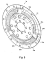
- FIG. 8 shows a development of the vibration damper 1 to 1d of FIGS. 1 to 7 in the form of the vibration damper 1e with a threefold division of the formed as a bow springs 25e energy storage 24e in partial view, in which only the disc part 4e of the first flywheel and the flange segments of the second flywheel and a portion of the energy storage 24e are shown.
- the disk part 4e is cup-shaped, in the bottom of the pot 43, the energy storage are substantially completely absorbed to form a closed on three sides annular chamber 10e.
- the annular chamber 10e can be closed by a substantially flat trained, not shown disk part, such as an annular cover.
- the disk part closing off the annular chamber 10e can have an axial projection for receiving a toothed rim, an additional mass or the like or can be folded radially on the outside.
- the structure of the vibration damper 1 for example, to the structure of the vibration damper 1 to 1d of FIGS. 1 to 7 be ajar.
Landscapes
- Engineering & Computer Science (AREA)
- General Engineering & Computer Science (AREA)
- Physics & Mathematics (AREA)
- Acoustics & Sound (AREA)
- Aviation & Aerospace Engineering (AREA)
- Mechanical Engineering (AREA)
- Mechanical Operated Clutches (AREA)
- Braking Arrangements (AREA)
- Connection Of Motors, Electrical Generators, Mechanical Devices, And The Like (AREA)
Claims (9)
- Amortisseur de vibrations (1, 1a, 1b, 1c, 1d, 1e), disposé au niveau d'une unité d'entraînement comprenant un arbre d'entraînement, avec deux masses d'inertie (2, 3) pouvant tourner l'une par rapport à l'autre à l'encontre de l'action de plusieurs accumulateurs d'énergie (24, 24e) disposés sur la périphérie, une première des masses d'inertie (2) présentant plusieurs parties de disque (4, 4b, 4d, 4e ; 9, 9a, 9b, 9c, 9d) connectées les unes aux autres, formant une chambre annulaire (10, 10e) pour recevoir les accumulateurs d'énergie (24, 24e), et une deuxième des masses d'inertie (3) présentant plusieurs dispositifs de précontrainte (12, 12e) venant en prise depuis l'intérieur radialement dans la chambre annulaire (10, 10e), agissant dans la direction périphérique sur les accumulateurs d'énergie (24, 24e), à chaque fois un dispositif de précontrainte (12, 12e) étant formé d'un parmi plusieurs segments de bride (18, 18e) répartis sur la périphérie et reçus sur la deuxième masse d'inertie (3),
caractérisé en ce que les dispositifs de précontrainte (12, 12e) viennent en prise radialement à chaque fois à travers une région (22) orientée essentiellement axialement présentant des évidements (26, 26b, 26e) d'une partie de disque (4, 4b, 4d, 4e) de la première masse d'inertie (2). - Amortisseur de vibrations (1, 1a, 1b, 1c, 1d) selon la revendication 1, caractérisé en ce qu'une première partie de disque (4, 4b, 4d) reçue sur l'arbre d'entraînement de l'unité d'entraînement est coudée axialement dans la région des évidements (26, 26b).
- Amortisseur de vibrations (1, 1a, 1b, 1c, 1d) selon la revendication 2, caractérisé en ce que la deuxième masse d'inertie (3) est disposée radialement à l'intérieur d'un insert (28) axial disposé radialement à l'extérieur sur la partie de disque coudée (4, 4b, 4d).
- Amortisseur de vibrations (1, 1a, 1b, 1c, 1d) selon l'une quelconque des revendications 1 à 3, caractérisé en ce qu'une première partie de disque (4, 4b, 4d) forme une paroi tournée vers la deuxième masse d'inertie et une deuxième partie de disque (9, 9a, 9b, 9c, 9d) forme une paroi tournée vers l'unité d'entraînement et, au moyen d'un insert disposé radialement à l'extérieur (31, 31a), forme une paroi radialement extérieure de la chambre annulaire (10).
- Amortisseur de vibrations (1, 1a) selon la revendication 4, caractérisé en ce que les deux parties de disque (4, 9, 9a) sont placées l'une contre l'autre en position adjacente à un cercle de vissage (13) pour la fixation de l'amortisseur de vibrations (1, 1a) à l'arbre d'entraînement.
- Amortisseur de vibrations (1, 1a, 1b, 1c, 1d, 1e) selon l'une quelconque des revendications 1 à 5, caractérisé en ce que les parties de disque (4, 4b, 4d, 4e ; 9a, 9b, 9c, 9d) sont soudées de manière hermétique les unes aux autres radialement à l'extérieur.
- Amortisseur de vibrations (1, 1a, 1b, 1c, 1d) selon l'une quelconque des revendications 1 à 6, caractérisé en ce que les parties de disque (4, 4b, 4d ; 9a, 9b, 9c, 9d) présentent une épaisseur de matériau différente.
- Amortisseur de vibrations (1b, 1d) selon l'une quelconque des revendications 1 à 7, caractérisé en ce qu'un orifice estampé radialement interne d'une partie de disque (4b ; 9d) est réalisé sous forme de bague de renforcement ou de bride de palier (32b, 32d) de la première masse d'inertie (2).
- Amortisseur de vibrations (1, 1a, 1c, 1d) selon l'une quelconque des revendications 1 à 8, caractérisé en ce qu'une couronne dentée (29) reçue radialement à l'extérieur sur l'amortisseur de vibrations (1, 1a, 1c, 1d) et disposée essentiellement axialement à la même hauteur que la deuxième masse d'inertie (3) est centrée au moyen d'une partie de disque d'une seule pièce (4, 4d) sur l'arbre d'entraînement.
Applications Claiming Priority (3)
| Application Number | Priority Date | Filing Date | Title |
|---|---|---|---|
| DE102009019071 | 2009-04-27 | ||
| DE102010008361 | 2010-02-18 | ||
| PCT/DE2010/000416 WO2010127653A1 (fr) | 2009-04-27 | 2010-04-12 | Amortisseur de vibrations |
Publications (2)
| Publication Number | Publication Date |
|---|---|
| EP2425149A1 EP2425149A1 (fr) | 2012-03-07 |
| EP2425149B1 true EP2425149B1 (fr) | 2014-06-11 |
Family
ID=42556972
Family Applications (1)
| Application Number | Title | Priority Date | Filing Date |
|---|---|---|---|
| EP10717512.7A Not-in-force EP2425149B1 (fr) | 2009-04-27 | 2010-04-12 | Amortisseur de vibrations |
Country Status (4)
| Country | Link |
|---|---|
| EP (1) | EP2425149B1 (fr) |
| CN (1) | CN102356251B (fr) |
| DE (2) | DE102010014677A1 (fr) |
| WO (1) | WO2010127653A1 (fr) |
Families Citing this family (8)
| Publication number | Priority date | Publication date | Assignee | Title |
|---|---|---|---|---|
| WO2014063693A1 (fr) | 2012-10-25 | 2014-05-01 | Schaeffler Technologies AG & Co. KG | Amortisseur de vibrations de torsion |
| CN103527786B (zh) * | 2013-10-28 | 2016-05-18 | 北京石油化工学院 | 飞轮低温焊接真空密封装置 |
| DE102014211654A1 (de) | 2014-06-18 | 2015-12-24 | Schaeffler Technologies AG & Co. KG | Drehschwingungsdämpfer und Verfahren zum Herstellen eines Drehschwingungsdämpfers |
| DE102018105262B4 (de) * | 2018-03-07 | 2023-09-21 | Vibracoustic Se | Sicherungs- und Zentriermittel sowie eine Schwingungsdämpfungsvorrichtung |
| FR3082259B1 (fr) * | 2018-06-08 | 2020-06-26 | Valeo Embrayages | Volant d'inertie a deux masses |
| FR3086718B1 (fr) * | 2018-09-27 | 2021-04-30 | Valeo Embrayages | Double volant amortisseur, en particulier pour vehicule automobile |
| DE102020108512A1 (de) * | 2020-03-27 | 2021-09-30 | Schaeffler Technologies AG & Co. KG | Zweimassenschwungrad mit Handhabungseingriff |
| DE102021131869A1 (de) | 2021-12-03 | 2023-06-07 | Schaeffler Technologies AG & Co. KG | Drehschwingungsdämpfer |
Family Cites Families (9)
| Publication number | Priority date | Publication date | Assignee | Title |
|---|---|---|---|---|
| DE4117582B4 (de) * | 1990-05-31 | 2008-02-14 | Luk Lamellen Und Kupplungsbau Beteiligungs Kg | Drehmomentübertragungseinrichtung |
| DE4117584B4 (de) * | 1990-05-31 | 2006-09-07 | Luk Lamellen Und Kupplungsbau Beteiligungs Kg | Geteiltes Schwungrad |
| DE4340175B4 (de) * | 1992-12-07 | 2013-02-21 | Schaeffler Technologies AG & Co. KG | Einrichtung zum Kompensieren von Drehstößen |
| FR2698936B1 (fr) * | 1992-12-07 | 1996-01-19 | Luk Lamellen & Kupplungsbau | Dispositif pour compenser des a-coups en rotation. |
| ATE532987T1 (de) * | 2003-07-28 | 2011-11-15 | Schaeffler Technologies Gmbh | Drehschwingungsdämpfer |
| EP1904760B1 (fr) * | 2005-07-14 | 2015-06-17 | Schaeffler Technologies AG & Co. KG | Dispositif d'amortissement de vibrations notamment destine a un volant a deux masses |
| DE102006030136A1 (de) * | 2005-07-14 | 2007-01-25 | Luk Lamellen Und Kupplungsbau Beteiligungs Kg | Torsionsschwingungsdämpfer |
| KR20080024152A (ko) * | 2005-07-14 | 2008-03-17 | 루크 라멜렌 운트 쿠플룽스바우베타일리궁스 카게 | 진동 감쇠 유닛, 특히 듀얼-매스 플라이휠 |
| DE102008023361A1 (de) | 2007-05-31 | 2008-12-04 | Luk Lamellen Und Kupplungsbau Beteiligungs Kg | Torsionsschwingungsdämpfer |
-
2010
- 2010-04-12 CN CN201080012252.6A patent/CN102356251B/zh not_active Expired - Fee Related
- 2010-04-12 WO PCT/DE2010/000416 patent/WO2010127653A1/fr not_active Ceased
- 2010-04-12 EP EP10717512.7A patent/EP2425149B1/fr not_active Not-in-force
- 2010-04-12 DE DE102010014677A patent/DE102010014677A1/de not_active Withdrawn
- 2010-04-12 DE DE112010001789T patent/DE112010001789A5/de not_active Withdrawn
Also Published As
| Publication number | Publication date |
|---|---|
| CN102356251B (zh) | 2014-12-10 |
| DE112010001789A5 (de) | 2012-11-08 |
| DE102010014677A1 (de) | 2011-01-13 |
| WO2010127653A1 (fr) | 2010-11-11 |
| CN102356251A (zh) | 2012-02-15 |
| EP2425149A1 (fr) | 2012-03-07 |
Similar Documents
| Publication | Publication Date | Title |
|---|---|---|
| EP2425149B1 (fr) | Amortisseur de vibrations | |
| DE102009042825B4 (de) | Drehmomentübertragungseinrichtung | |
| WO2011150911A2 (fr) | Amortisseur de vibrations torsionnelles | |
| DE102010023373A1 (de) | Zweimassenschwungrad | |
| DE102014206738A1 (de) | Zweimassenschwungrad | |
| EP2888505B1 (fr) | Amortisseur de vibrations de torsion | |
| DE102012200966A1 (de) | Drehschwingungsdämpfer in einem Antriebsstrang eines Kraftfahrzeugs | |
| DE4420927A1 (de) | Drehmomentübertragungseinrichtung | |
| DE102012219798A1 (de) | Fliehkraftpendeleinrichtung | |
| DE102019118504A1 (de) | Drehschwingungsdämpfer | |
| WO2015090308A1 (fr) | Amortisseur de vibrations de torsion muni d'un pendule centrifuge | |
| DE69709048T2 (de) | Zweimassenschwungrad, insbesondere für kraftfahrzeuge, mit verbesserter reibungsdämpfung von schwingungen | |
| EP1923599A2 (fr) | Volant double masse | |
| DE3904845C2 (de) | Drehschwingungsdämpfer mit elastischen Umfangselementen, insbesondere für Kraftfahrzeuge | |
| DE102020108512A1 (de) | Zweimassenschwungrad mit Handhabungseingriff | |
| WO2017101925A1 (fr) | Pendule à force centrifuge à membrane d'étanchéité sous forme de ressort diaphragme et procédé d'équilibrage d'un tel pendule à force centrifuge | |
| DE102016223192A1 (de) | Fliehkraftpendeleinrichtung | |
| DE102015210013A1 (de) | Einmassenschwungrad | |
| DE102014211654A1 (de) | Drehschwingungsdämpfer und Verfahren zum Herstellen eines Drehschwingungsdämpfers | |
| DE102018102557A1 (de) | Drehschwingungsdämpfer | |
| DE102019126172A1 (de) | Drehschwingungsdämpfer | |
| DE102014211744A1 (de) | Drehschwingungsdämpfer | |
| DE102012212817A1 (de) | Zweimassenschwungrad | |
| DE102009041467A1 (de) | Drehschwingungsdämpfer | |
| WO2017092755A1 (fr) | Dispositif pendulaire centrifuge et dispositif de transmission de couple |
Legal Events
| Date | Code | Title | Description |
|---|---|---|---|
| PUAI | Public reference made under article 153(3) epc to a published international application that has entered the european phase |
Free format text: ORIGINAL CODE: 0009012 |
|
| 17P | Request for examination filed |
Effective date: 20111128 |
|
| AK | Designated contracting states |
Kind code of ref document: A1 Designated state(s): AT BE BG CH CY CZ DE DK EE ES FI FR GB GR HR HU IE IS IT LI LT LU LV MC MK MT NL NO PL PT RO SE SI SK SM TR |
|
| RAP1 | Party data changed (applicant data changed or rights of an application transferred) |
Owner name: SCHAEFFLER TECHNOLOGIES AG & CO. KG |
|
| DAX | Request for extension of the european patent (deleted) | ||
| GRAP | Despatch of communication of intention to grant a patent |
Free format text: ORIGINAL CODE: EPIDOSNIGR1 |
|
| INTG | Intention to grant announced |
Effective date: 20131018 |
|
| GRAS | Grant fee paid |
Free format text: ORIGINAL CODE: EPIDOSNIGR3 |
|
| RAP1 | Party data changed (applicant data changed or rights of an application transferred) |
Owner name: SCHAEFFLER TECHNOLOGIES GMBH & CO. KG |
|
| GRAA | (expected) grant |
Free format text: ORIGINAL CODE: 0009210 |
|
| AK | Designated contracting states |
Kind code of ref document: B1 Designated state(s): AT BE BG CH CY CZ DE DK EE ES FI FR GB GR HR HU IE IS IT LI LT LU LV MC MK MT NL NO PL PT RO SE SI SK SM TR |
|
| REG | Reference to a national code |
Ref country code: GB Ref legal event code: FG4D Free format text: NOT ENGLISH |
|
| REG | Reference to a national code |
Ref country code: CH Ref legal event code: EP |
|
| REG | Reference to a national code |
Ref country code: IE Ref legal event code: FG4D Free format text: LANGUAGE OF EP DOCUMENT: GERMAN |
|
| REG | Reference to a national code |
Ref country code: AT Ref legal event code: REF Ref document number: 672430 Country of ref document: AT Kind code of ref document: T Effective date: 20140715 |
|
| REG | Reference to a national code |
Ref country code: DE Ref legal event code: R096 Ref document number: 502010007186 Country of ref document: DE Effective date: 20140724 |
|
| PG25 | Lapsed in a contracting state [announced via postgrant information from national office to epo] |
Ref country code: NO Free format text: LAPSE BECAUSE OF FAILURE TO SUBMIT A TRANSLATION OF THE DESCRIPTION OR TO PAY THE FEE WITHIN THE PRESCRIBED TIME-LIMIT Effective date: 20140911 Ref country code: LT Free format text: LAPSE BECAUSE OF FAILURE TO SUBMIT A TRANSLATION OF THE DESCRIPTION OR TO PAY THE FEE WITHIN THE PRESCRIBED TIME-LIMIT Effective date: 20140611 Ref country code: FI Free format text: LAPSE BECAUSE OF FAILURE TO SUBMIT A TRANSLATION OF THE DESCRIPTION OR TO PAY THE FEE WITHIN THE PRESCRIBED TIME-LIMIT Effective date: 20140611 Ref country code: GR Free format text: LAPSE BECAUSE OF FAILURE TO SUBMIT A TRANSLATION OF THE DESCRIPTION OR TO PAY THE FEE WITHIN THE PRESCRIBED TIME-LIMIT Effective date: 20140912 |
|
| REG | Reference to a national code |
Ref country code: NL Ref legal event code: VDEP Effective date: 20140611 |
|
| REG | Reference to a national code |
Ref country code: LT Ref legal event code: MG4D |
|
| PG25 | Lapsed in a contracting state [announced via postgrant information from national office to epo] |
Ref country code: SE Free format text: LAPSE BECAUSE OF FAILURE TO SUBMIT A TRANSLATION OF THE DESCRIPTION OR TO PAY THE FEE WITHIN THE PRESCRIBED TIME-LIMIT Effective date: 20140611 Ref country code: LV Free format text: LAPSE BECAUSE OF FAILURE TO SUBMIT A TRANSLATION OF THE DESCRIPTION OR TO PAY THE FEE WITHIN THE PRESCRIBED TIME-LIMIT Effective date: 20140611 Ref country code: HR Free format text: LAPSE BECAUSE OF FAILURE TO SUBMIT A TRANSLATION OF THE DESCRIPTION OR TO PAY THE FEE WITHIN THE PRESCRIBED TIME-LIMIT Effective date: 20140611 |
|
| PG25 | Lapsed in a contracting state [announced via postgrant information from national office to epo] |
Ref country code: SK Free format text: LAPSE BECAUSE OF FAILURE TO SUBMIT A TRANSLATION OF THE DESCRIPTION OR TO PAY THE FEE WITHIN THE PRESCRIBED TIME-LIMIT Effective date: 20140611 Ref country code: RO Free format text: LAPSE BECAUSE OF FAILURE TO SUBMIT A TRANSLATION OF THE DESCRIPTION OR TO PAY THE FEE WITHIN THE PRESCRIBED TIME-LIMIT Effective date: 20140611 Ref country code: PT Free format text: LAPSE BECAUSE OF FAILURE TO SUBMIT A TRANSLATION OF THE DESCRIPTION OR TO PAY THE FEE WITHIN THE PRESCRIBED TIME-LIMIT Effective date: 20141013 Ref country code: EE Free format text: LAPSE BECAUSE OF FAILURE TO SUBMIT A TRANSLATION OF THE DESCRIPTION OR TO PAY THE FEE WITHIN THE PRESCRIBED TIME-LIMIT Effective date: 20140611 Ref country code: ES Free format text: LAPSE BECAUSE OF FAILURE TO SUBMIT A TRANSLATION OF THE DESCRIPTION OR TO PAY THE FEE WITHIN THE PRESCRIBED TIME-LIMIT Effective date: 20140611 Ref country code: CZ Free format text: LAPSE BECAUSE OF FAILURE TO SUBMIT A TRANSLATION OF THE DESCRIPTION OR TO PAY THE FEE WITHIN THE PRESCRIBED TIME-LIMIT Effective date: 20140611 |
|
| PG25 | Lapsed in a contracting state [announced via postgrant information from national office to epo] |
Ref country code: NL Free format text: LAPSE BECAUSE OF FAILURE TO SUBMIT A TRANSLATION OF THE DESCRIPTION OR TO PAY THE FEE WITHIN THE PRESCRIBED TIME-LIMIT Effective date: 20140611 Ref country code: PL Free format text: LAPSE BECAUSE OF FAILURE TO SUBMIT A TRANSLATION OF THE DESCRIPTION OR TO PAY THE FEE WITHIN THE PRESCRIBED TIME-LIMIT Effective date: 20140611 Ref country code: IS Free format text: LAPSE BECAUSE OF FAILURE TO SUBMIT A TRANSLATION OF THE DESCRIPTION OR TO PAY THE FEE WITHIN THE PRESCRIBED TIME-LIMIT Effective date: 20141011 |
|
| RAP2 | Party data changed (patent owner data changed or rights of a patent transferred) |
Owner name: SCHAEFFLER TECHNOLOGIES AG & CO. KG |
|
| REG | Reference to a national code |
Ref country code: DE Ref legal event code: R097 Ref document number: 502010007186 Country of ref document: DE |
|
| PLBE | No opposition filed within time limit |
Free format text: ORIGINAL CODE: 0009261 |
|
| STAA | Information on the status of an ep patent application or granted ep patent |
Free format text: STATUS: NO OPPOSITION FILED WITHIN TIME LIMIT |
|
| PG25 | Lapsed in a contracting state [announced via postgrant information from national office to epo] |
Ref country code: IT Free format text: LAPSE BECAUSE OF FAILURE TO SUBMIT A TRANSLATION OF THE DESCRIPTION OR TO PAY THE FEE WITHIN THE PRESCRIBED TIME-LIMIT Effective date: 20140611 Ref country code: DK Free format text: LAPSE BECAUSE OF FAILURE TO SUBMIT A TRANSLATION OF THE DESCRIPTION OR TO PAY THE FEE WITHIN THE PRESCRIBED TIME-LIMIT Effective date: 20140611 |
|
| REG | Reference to a national code |
Ref country code: DE Ref legal event code: R081 Ref document number: 502010007186 Country of ref document: DE Owner name: SCHAEFFLER TECHNOLOGIES AG & CO. KG, DE Free format text: FORMER OWNER: SCHAEFFLER TECHNOLOGIES GMBH & CO. KG, 91074 HERZOGENAURACH, DE Effective date: 20150407 |
|
| 26N | No opposition filed |
Effective date: 20150312 |
|
| REG | Reference to a national code |
Ref country code: DE Ref legal event code: R097 Ref document number: 502010007186 Country of ref document: DE Effective date: 20150312 |
|
| PG25 | Lapsed in a contracting state [announced via postgrant information from national office to epo] |
Ref country code: SI Free format text: LAPSE BECAUSE OF FAILURE TO SUBMIT A TRANSLATION OF THE DESCRIPTION OR TO PAY THE FEE WITHIN THE PRESCRIBED TIME-LIMIT Effective date: 20140611 |
|
| PG25 | Lapsed in a contracting state [announced via postgrant information from national office to epo] |
Ref country code: MC Free format text: LAPSE BECAUSE OF FAILURE TO SUBMIT A TRANSLATION OF THE DESCRIPTION OR TO PAY THE FEE WITHIN THE PRESCRIBED TIME-LIMIT Effective date: 20140611 Ref country code: LU Free format text: LAPSE BECAUSE OF FAILURE TO SUBMIT A TRANSLATION OF THE DESCRIPTION OR TO PAY THE FEE WITHIN THE PRESCRIBED TIME-LIMIT Effective date: 20150412 |
|
| REG | Reference to a national code |
Ref country code: CH Ref legal event code: PL |
|
| GBPC | Gb: european patent ceased through non-payment of renewal fee |
Effective date: 20150412 |
|
| REG | Reference to a national code |
Ref country code: IE Ref legal event code: MM4A |
|
| PG25 | Lapsed in a contracting state [announced via postgrant information from national office to epo] |
Ref country code: CH Free format text: LAPSE BECAUSE OF NON-PAYMENT OF DUE FEES Effective date: 20150430 Ref country code: GB Free format text: LAPSE BECAUSE OF NON-PAYMENT OF DUE FEES Effective date: 20150412 Ref country code: LI Free format text: LAPSE BECAUSE OF NON-PAYMENT OF DUE FEES Effective date: 20150430 |
|
| REG | Reference to a national code |
Ref country code: FR Ref legal event code: PLFP Year of fee payment: 7 |
|
| PG25 | Lapsed in a contracting state [announced via postgrant information from national office to epo] |
Ref country code: IE Free format text: LAPSE BECAUSE OF NON-PAYMENT OF DUE FEES Effective date: 20150412 |
|
| REG | Reference to a national code |
Ref country code: AT Ref legal event code: MM01 Ref document number: 672430 Country of ref document: AT Kind code of ref document: T Effective date: 20150412 |
|
| PG25 | Lapsed in a contracting state [announced via postgrant information from national office to epo] |
Ref country code: AT Free format text: LAPSE BECAUSE OF NON-PAYMENT OF DUE FEES Effective date: 20150412 |
|
| PG25 | Lapsed in a contracting state [announced via postgrant information from national office to epo] |
Ref country code: MT Free format text: LAPSE BECAUSE OF FAILURE TO SUBMIT A TRANSLATION OF THE DESCRIPTION OR TO PAY THE FEE WITHIN THE PRESCRIBED TIME-LIMIT Effective date: 20140611 |
|
| REG | Reference to a national code |
Ref country code: FR Ref legal event code: PLFP Year of fee payment: 8 |
|
| PG25 | Lapsed in a contracting state [announced via postgrant information from national office to epo] |
Ref country code: BG Free format text: LAPSE BECAUSE OF FAILURE TO SUBMIT A TRANSLATION OF THE DESCRIPTION OR TO PAY THE FEE WITHIN THE PRESCRIBED TIME-LIMIT Effective date: 20140611 Ref country code: SM Free format text: LAPSE BECAUSE OF FAILURE TO SUBMIT A TRANSLATION OF THE DESCRIPTION OR TO PAY THE FEE WITHIN THE PRESCRIBED TIME-LIMIT Effective date: 20140611 Ref country code: HU Free format text: LAPSE BECAUSE OF FAILURE TO SUBMIT A TRANSLATION OF THE DESCRIPTION OR TO PAY THE FEE WITHIN THE PRESCRIBED TIME-LIMIT; INVALID AB INITIO Effective date: 20100412 |
|
| PG25 | Lapsed in a contracting state [announced via postgrant information from national office to epo] |
Ref country code: CY Free format text: LAPSE BECAUSE OF FAILURE TO SUBMIT A TRANSLATION OF THE DESCRIPTION OR TO PAY THE FEE WITHIN THE PRESCRIBED TIME-LIMIT Effective date: 20140611 |
|
| PG25 | Lapsed in a contracting state [announced via postgrant information from national office to epo] |
Ref country code: BE Free format text: LAPSE BECAUSE OF NON-PAYMENT OF DUE FEES Effective date: 20150430 |
|
| PG25 | Lapsed in a contracting state [announced via postgrant information from national office to epo] |
Ref country code: TR Free format text: LAPSE BECAUSE OF FAILURE TO SUBMIT A TRANSLATION OF THE DESCRIPTION OR TO PAY THE FEE WITHIN THE PRESCRIBED TIME-LIMIT Effective date: 20140611 |
|
| REG | Reference to a national code |
Ref country code: FR Ref legal event code: PLFP Year of fee payment: 9 |
|
| PG25 | Lapsed in a contracting state [announced via postgrant information from national office to epo] |
Ref country code: MK Free format text: LAPSE BECAUSE OF FAILURE TO SUBMIT A TRANSLATION OF THE DESCRIPTION OR TO PAY THE FEE WITHIN THE PRESCRIBED TIME-LIMIT Effective date: 20140611 |
|
| PGFP | Annual fee paid to national office [announced via postgrant information from national office to epo] |
Ref country code: DE Payment date: 20210618 Year of fee payment: 12 Ref country code: FR Payment date: 20210423 Year of fee payment: 12 |
|
| REG | Reference to a national code |
Ref country code: DE Ref legal event code: R119 Ref document number: 502010007186 Country of ref document: DE |
|
| PG25 | Lapsed in a contracting state [announced via postgrant information from national office to epo] |
Ref country code: FR Free format text: LAPSE BECAUSE OF NON-PAYMENT OF DUE FEES Effective date: 20220430 Ref country code: DE Free format text: LAPSE BECAUSE OF NON-PAYMENT OF DUE FEES Effective date: 20221103 |
|
| P01 | Opt-out of the competence of the unified patent court (upc) registered |
Effective date: 20230523 |