EP2425143B1 - Procédé permettant de diminuer ou d'éviter les bruits de résonance d'une unité de friction - Google Patents
Procédé permettant de diminuer ou d'éviter les bruits de résonance d'une unité de friction Download PDFInfo
- Publication number
- EP2425143B1 EP2425143B1 EP11715479.9A EP11715479A EP2425143B1 EP 2425143 B1 EP2425143 B1 EP 2425143B1 EP 11715479 A EP11715479 A EP 11715479A EP 2425143 B1 EP2425143 B1 EP 2425143B1
- Authority
- EP
- European Patent Office
- Prior art keywords
- friction
- friction lining
- natural
- vibration
- friction unit
- Prior art date
- Legal status (The legal status is an assumption and is not a legal conclusion. Google has not performed a legal analysis and makes no representation as to the accuracy of the status listed.)
- Not-in-force
Links
- 238000000034 method Methods 0.000 title claims description 21
- 238000005259 measurement Methods 0.000 claims description 12
- 230000002596 correlated effect Effects 0.000 claims description 4
- 238000003754 machining Methods 0.000 claims description 4
- 238000012545 processing Methods 0.000 description 14
- 238000004519 manufacturing process Methods 0.000 description 12
- 238000012805 post-processing Methods 0.000 description 11
- 230000000875 corresponding effect Effects 0.000 description 4
- 230000000694 effects Effects 0.000 description 3
- 238000013016 damping Methods 0.000 description 2
- 238000011161 development Methods 0.000 description 2
- 238000012360 testing method Methods 0.000 description 2
- 238000004026 adhesive bonding Methods 0.000 description 1
- 238000004458 analytical method Methods 0.000 description 1
- 238000013459 approach Methods 0.000 description 1
- 238000011143 downstream manufacturing Methods 0.000 description 1
- 230000005284 excitation Effects 0.000 description 1
- 239000002783 friction material Substances 0.000 description 1
- 239000000463 material Substances 0.000 description 1
- 238000010002 mechanical finishing Methods 0.000 description 1
- 238000003199 nucleic acid amplification method Methods 0.000 description 1
- 230000010355 oscillation Effects 0.000 description 1
- 238000003825 pressing Methods 0.000 description 1
- 238000012552 review Methods 0.000 description 1
- 238000001228 spectrum Methods 0.000 description 1
- 210000002105 tongue Anatomy 0.000 description 1
- 239000013598 vector Substances 0.000 description 1
Images


Classifications
-
- F—MECHANICAL ENGINEERING; LIGHTING; HEATING; WEAPONS; BLASTING
- F16—ENGINEERING ELEMENTS AND UNITS; GENERAL MEASURES FOR PRODUCING AND MAINTAINING EFFECTIVE FUNCTIONING OF MACHINES OR INSTALLATIONS; THERMAL INSULATION IN GENERAL
- F16D—COUPLINGS FOR TRANSMITTING ROTATION; CLUTCHES; BRAKES
- F16D65/00—Parts or details
- F16D65/0006—Noise or vibration control
-
- F—MECHANICAL ENGINEERING; LIGHTING; HEATING; WEAPONS; BLASTING
- F16—ENGINEERING ELEMENTS AND UNITS; GENERAL MEASURES FOR PRODUCING AND MAINTAINING EFFECTIVE FUNCTIONING OF MACHINES OR INSTALLATIONS; THERMAL INSULATION IN GENERAL
- F16D—COUPLINGS FOR TRANSMITTING ROTATION; CLUTCHES; BRAKES
- F16D65/00—Parts or details
- F16D65/02—Braking members; Mounting thereof
- F16D65/04—Bands, shoes or pads; Pivots or supporting members therefor
- F16D65/092—Bands, shoes or pads; Pivots or supporting members therefor for axially-engaging brakes, e.g. disc brakes
-
- F—MECHANICAL ENGINEERING; LIGHTING; HEATING; WEAPONS; BLASTING
- F16—ENGINEERING ELEMENTS AND UNITS; GENERAL MEASURES FOR PRODUCING AND MAINTAINING EFFECTIVE FUNCTIONING OF MACHINES OR INSTALLATIONS; THERMAL INSULATION IN GENERAL
- F16D—COUPLINGS FOR TRANSMITTING ROTATION; CLUTCHES; BRAKES
- F16D69/00—Friction linings; Attachment thereof; Selection of coacting friction substances or surfaces
- F16D2069/004—Profiled friction surfaces, e.g. grooves, dimples
Definitions
- the present invention relates to a method for reducing or avoiding resonance noise of a friction unit, which has a carrier plate with a friction lining held thereon.
- the DE 199 03 757 A1 deals with the problem of avoiding the noise of friction brakes and friction clutches.
- the natural frequency of the friction brake or friction clutch is adjusted by forming correspondingly dimensioned tongues (resonators) in the carrier plate.
- the DE 196 10 699 A1 describes a clutch disc with friction lining.
- corresponding recesses which can be of different widths, are formed in the friction lining.
- WO 95/25912 discloses a friction unit in which circular recesses or slots are formed in the friction lining to prevent or prevent resonance noises. The introduction of the recesses or slots is made to the Places where force vectors indicate the most likely occurrence of audible frequencies.
- JP 10 002 361 A discloses a method for determining the natural frequency of an unprocessed friction unit.
- the natural frequency of the processed friction unit is determined by considering the difference in weight between a target weight value of the processed friction unit and the actual weight of the friction unit.
- the present invention has for its object to provide a method by which the friction units, as produced in the series to adjust so that they are particularly free of resonance noises, and regardless of which manufacturing tolerances the individual friction units of series production subject.
- the present object is achieved by a method for reducing or avoiding resonance noise of a friction unit, which has a carrier plate with a friction lining held thereon, in which the natural vibration behavior of the respective produced friction units, referred to as characteristic frequency measurement, is determined and a mechanical Post-processing of the friction lining takes place, wherein for the post-processing a table is used which contains characteristic frequency reference values for the specific friction unit type, wherein the characteristic frequencies for the table of the friction unit type are determined by means of a friction unit of this type, by this friction unit type Vibrations defined frequency is applied and the resulting natural vibrations of the friction unit and resulting natural vibrations are measured by engaging the geometry of the friction lining, and wherein at a deviation of the resulting Natural vibrations of a predefined, low-noise vibration range The geometry of the produced friction lining is changed according to the table values to change the natural vibration behavior so that after machining the range of natural vibrations falls within the defined vibration range, free of resonance noises.
- the natural frequency measurement is replaced by a characteristic frequency measurement in the series.
- friction units may in particular be parts of brakes, for example brake pads, and parts of clutches, for example clutch plates, which are each constructed at least from a carrier plate and a friction unit held thereon.
- a vibration analysis can be carried out during the production process of friction linings with the aim of subsequently adapting the friction lining to a positive natural frequency for later use without changing the other required properties.
- the produced series linings or mass produced friction units can be checked. If the friction units approach these characteristic frequency limits, the characteristic frequency, for example due to a downstream processing, can be reached. B. by post-processing of the grooves introduced into the lining, for example, their depths, widths and shapes are changed. Furthermore, the characteristic frequency can be changed by editing a marginal area of the pad.
- the edge region of the friction lining may be at least partially rounded off and / or run obliquely starting from a contact surface facing the brake disk in the direction of the carrier plate. The contact surface is the surface of the friction lining, which can come into frictional contact with the brake disk.
- the contact surface of the friction lining facing the brake disk partially or entirely obliquely. That is, the friction lining is formed such that the distance between the contact surface of the friction lining and the brake disc, starting from an edge of the friction lining until at least partially changed to an edge opposite this edge, when the friction lining is not in frictional contact with the brake disc.
- the degree of processing performed corresponds to the characteristic frequency shift correlated to this processing. Based on graduated processing patterns, a correlation between the degree of processing and the frequency shift over a wide characteristic frequency range can be defined, so that a re-examination after processing is eliminated. At the end there is a brake pad, which undergoes a frequency shift in the, for later application, safer frequency range after pressing and hardening by the subsequent measurement and the possibly required step, that is in a frequency range that leads to no audible noise.
- the change in the characteristic frequency can be done for example by a mechanical post-processing or by attaching additional masses or by gluing appropriately tuned damping elements.
- a post-processing of the friction lining, in which material is removed at certain defined locations, is preferred.
- Essential for the inventive method is that for adjusting the natural frequency of a friction unit initially different frequency patterns are produced. For example, interferences with the geometry or, for example, changes in the density of the lining or friction material are undertaken for this purpose. These frequency patterns then have a gradation in the natural frequency. With these patterns, boundary patterns are determined in practical tests, that is, pattern geometries in which, due to their natural frequency, noises are produced during the operation of the friction unit.
- Such boundary patterns are therefore defined as patterns which determine the upper and lower limits of the natural frequency at which the friction unit can still be operated without noise. On the basis of these limit patterns, the correlating characteristic frequency is determined.
- the friction unit or the friction lining is not free swinging, but clamped, is measured, for. B. adequately as the friction unit or friction lining is clamped in the friction unit.
- the loose or free end can be excited, for example, with a shaker, that is a voice coil, based on the loudspeaker principle, and the resonance points are determined by the power consumption of the coil or by an accelerometer.
- a once excited component has at least one, often even several, resonance frequencies when passing through the frequency band of the decaying oscillation, which correspond to the natural frequencies when neglecting the damping. Resonances occur at the frequencies at which particularly large amplitudes occur due to self-amplification of the component. At this natural frequency, the characteristic frequency is correlated, which has the same shifted by the clamping in their resonance points resonance.
- the component is a cantilever, ie without any external influence, except for the excitation (eg suspended on a thin rope), the frequency at these resonance points is referred to as eigenfrequencies.
- the characteristic frequency can be correlated to the natural frequency. Due to the lower degrees of freedom in the characteristic frequency measurement and non-relevant harmonics are prevented, resulting in a better reproducibility of the resonance points.
- the friction unit is excited by means of a vibration generator. This measure is advantageous in that a specifically restricted frequency band can be traversed, which also has a greatly reduced measurement time result.
- the natural vibration of the friction unit can be determined by measuring the amplitude of the vibration generator.
- a preferred measure is that the natural vibrations of the friction unit are determined by measuring the power consumption of the vibration generator.
- the friction lining is preferably processed mechanically by preferably varying the depth and / or the width of a groove introduced into the friction lining in order to set the natural vibrations to the required value.
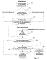
- the procedure as it is in FIG. 1 is shown with reference to a flow chart, is used to determine the characteristic frequency of friction units and for influencing or adjusting the characteristic frequency by a mechanical processing of the friction lining (blank) during the manufacturing process.
- FIG. 2 a device can be used, as shown schematically in FIG. 2 is shown.
- This device comprises a clamping device 1 with an upper clamping part 2 and a lower clamping part 3.
- the lower clamping part 3 is associated with a stationary support table 4, while the upper clamping part 2 via a pressure cylinder 5 in the direction of arrow 6 is displaceable.
- a brake shoe 7 is clamped approximately centrally in the example shown.
- This brake shoe 7 comprises a support plate 8, on which a friction lining 9 is held.
- the thus-clamped friction unit can be excited by means of a vibration generator, which is generally designated by the reference numeral 10.
- the vibration generator 10 engages with a holding part 11 in the support plate 8 of the friction unit 7, and that at the edge of the support plate 8, a.
- the support plate 8 is connected to the piston 12 of a counter-pressure cylinder 13.
- the vibration generator 10 and its holding part 11 the support plate 8 and thus the friction unit 7 perpendicular to the surface of the friction lining 9 in defined vibrations, indicated by the double arrow 14, are added.
- the impression cylinder 13 the contact of the support plate 8 is maintained to the holding part 11 of the vibration generator 10 during the measurement phase.
- the vibration generator 10 By measuring the amplitude or the power consumption of the vibration generator 10 can on the natural or characteristic frequency of the brake shoe or friction unit 7 are closed. With this arrangement, the frequency spectrum is traversed and determines the occurring resonance frequencies of the clamped friction unit 7. To determine the resonance frequency, the power consumption of the vibration generator can be used as a reference variable.
- the resonance frequency if a resonance occurs and leads to high noise, which was previously determined, can be selectively moved to a range in which no unwanted noise occurs.
- reference values for the groove depth and width are used, which are stored, for example, in a memory.
- these reference values are set.
- frequency pattern determined with staggered natural frequencies means that patterns are produced which receive specifically different natural frequencies through processing.
- the individual friction units are then checked in a step 101 during operation of a brake.
- This test includes in particular the noise of the brake at different speeds.
- This review sets an upper limit and a lower limit for limit patterns.
- the boundary patterns including the upper limit and the lower limit, are then set in graded processing patterns, which include values for the mechanical engagement in the friction lining to shift the natural frequencies of the brake shoe, as determined in step 102 with "determination of the characteristic frequencies, the frequency pattern, lower and upper limit for production ".
- step 103 the produced, fully cured brake linings are then used in step 103.
- step 104 a characteristic frequency measurement is then carried out. The measured values are then compared with the intervention limits.
- step 104 If, in step 104, the measured values are not within the range of the characteristic frequency of the limit patterns, a mechanical post-processing of the friction lining takes place in step 105 such that a shift in the characteristic frequency is achieved. For such post-processing is resorted to the data in the table 106, which includes the required correlation of a post-processing to the characteristic frequency shift.
- step 104 If, in step 104, the measurement shows that the measured values are within the range of the characteristic frequency of the limit patterns, the decision is made that the brake pad is in order, that is to say it has a controlled natural frequency, as indicated in step 107 is.
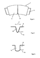
- FIG. 3 shows by way of example a friction unit or brake shoe 7 with support plate 8 and friction lining 9, as in the arrangement of FIG. 2 is used.
- a groove 15 is milled into the surface of the friction lining 9.
- FIG. 4 shows a V-shaped groove 15 which has a width of 1.7 mm at the point indicated by the arrow 16, while the width 17 in the region of the surface of the friction lining 9 has a value of 2.3 mm.
- This brake shoe 7 was with the device of FIG. 2 measured. Thereafter, the groove was changed to a shape in FIG. 5 is shown, which has an approximately U-shaped shape and also had a width 16 of 2.3 mm in the lower region.
- the frequency could be lowered by 8 hertz
- FIGS. 4 and 5 shows how the characteristic frequencies can be related to different processing stages of the friction lining in order to establish a table with reference values, which is used during the post-processing of the friction linings during series production.
- FIGS. 6 to 9 Further possibilities for processing the friction lining 7 are shown.
- the in FIG. 7 shown friction lining 7 has an edge region 19 which has an oblique course.
- the in FIG. 8 shown friction lining 7 also has an oblique edge portion 19.
- the in FIG. 9 shown friction lining 7 has a rounded edge portion 20.
Landscapes
- Engineering & Computer Science (AREA)
- General Engineering & Computer Science (AREA)
- Mechanical Engineering (AREA)
- Braking Arrangements (AREA)
- Mechanical Operated Clutches (AREA)
Claims (7)
- Procédé destiné à diminuer ou éviter les bruits de résonance d'une unité de frottement produite qui présente une plaque de support sur laquelle est maintenue une couche de frottement,
dans lequel le comportement d'auto-vibration (mesure de la fréquence caractéristique) des différentes unités de frottement produites est déterminé et un traitement mécanique de finition de la couche de frottement a lieu en cas d'apparition de bruits de résonance, le traitement de finition étant basé sur des valeurs déterminées préalablement qui contiennent des valeurs de référence de la fréquence caractéristique du type particulier d'unité de frottement,
les fréquences caractéristiques déterminées étant déterminées pour un tableau des types d'unité de frottement à l'aide d'une unité de frottement de ce type en appliquant sur ce type d'unité de frottement des vibrations de fréquence définie, les vibrations propres de l'unité de frottement qui en résultent ainsi que les vibrations propres qui surviennent étant mesurées tout en agissant sur la géométrie de sa couche de frottement,
en cas d'écart entre les vibrations propres qui surviennent par rapport à une plage prédéfinie de vibrations peu bruyantes, la géométrie de la couche de frottement produite est modifiée à l'aide des valeurs du tableau pour modifier le comportement d'auto-vibration de telle sorte qu'après le traitement, la plage des vibrations propres revienne dans la plage de vibrations définies, exempte de bruits de résonance. - Procédé selon la revendication 1, caractérisé en ce que les vibrations propres de l'unité de frottement sont excitées au moyen d'un générateur de vibrations.
- Procédé selon la revendication 2, caractérisé en ce que les vibrations propres de l'unité de frottement sont déterminées par mesure de l'amplitude du générateur de vibrations.
- Procédé selon la revendication 2, caractérisé en ce que les vibrations propres de l'unité de frottement sont déterminées par mesure de la puissance absorbée par le générateur de vibrations.
- Procédé selon l'une des revendications 1 à 4, caractérisé en ce que la géométrie de la couche de frottement est modifiée par modification de la profondeur et/ou de la largeur d'une rainure ménagée dans la couche de frottement, en vue d'ajuster les vibrations propres.
- Procédé selon l'une des revendications 1 à 5, caractérisé en ce que la géométrie de la couche de frottement est modifiée mécaniquement par modification de l'épaisseur de la couche de frottement, en vue d'ajuster les vibrations propres.
- Procédé selon l'une des revendications 1 à 6, caractérisé en ce que pour la mesure de la modification de la géométrie de la couche de frottement, on se réfère à un tableau dans lequel l'écart entre la vibration propre de la couche de frottement et la plage prédéfinie de vibrations est corrélé au degré de la modification de la géométrie qui doit être réalisée.
Applications Claiming Priority (2)
| Application Number | Priority Date | Filing Date | Title |
|---|---|---|---|
| DE102010027846A DE102010027846A1 (de) | 2010-04-16 | 2010-04-16 | Verfahren zum Vermindern bzw. Vermeiden von Resonanzgeräuschen einer Reibeinheit |
| PCT/EP2011/055849 WO2011128386A1 (fr) | 2010-04-16 | 2011-04-13 | Procédé permettant de diminuer ou d'éviter les bruits de résonance d'une unité de friction |
Publications (2)
| Publication Number | Publication Date |
|---|---|
| EP2425143A1 EP2425143A1 (fr) | 2012-03-07 |
| EP2425143B1 true EP2425143B1 (fr) | 2013-06-05 |
Family
ID=44226001
Family Applications (1)
| Application Number | Title | Priority Date | Filing Date |
|---|---|---|---|
| EP11715479.9A Not-in-force EP2425143B1 (fr) | 2010-04-16 | 2011-04-13 | Procédé permettant de diminuer ou d'éviter les bruits de résonance d'une unité de friction |
Country Status (4)
| Country | Link |
|---|---|
| EP (1) | EP2425143B1 (fr) |
| DE (1) | DE102010027846A1 (fr) |
| ES (1) | ES2422208T3 (fr) |
| WO (1) | WO2011128386A1 (fr) |
Families Citing this family (3)
| Publication number | Priority date | Publication date | Assignee | Title |
|---|---|---|---|---|
| DE102011121270B4 (de) * | 2011-12-15 | 2017-06-01 | Audi Ag | Verfahren zur Beurteilung der akustischen Qualität einer Bremsscheibe |
| DE102012020293A1 (de) * | 2012-10-17 | 2013-11-07 | Audi Ag | Verfahren zum Abstimmen der Eigenfrequenzen schwingungsbeanspruchter Bauteile an Kraftfahrzeugen |
| DE102013113546A1 (de) * | 2013-12-05 | 2015-06-11 | Knorr-Bremse Systeme für Nutzfahrzeuge GmbH | Bremsbelag mit einer Dämpfungseinrichtung für eine Scheibenbremse, eine Scheibenbremse mit einem solchen Bremsbelag und Verfahren zum Optimieren einer Dämpfungseinrichtung eines solchen Bremsbelags |
Family Cites Families (8)
| Publication number | Priority date | Publication date | Assignee | Title |
|---|---|---|---|---|
| US4705146A (en) * | 1984-04-02 | 1987-11-10 | Allied Corporation | Disc brake |
| US5456339A (en) * | 1994-03-23 | 1995-10-10 | Alliedsignal Inc. | Noise attenuated brake friction member |
| DE19610699A1 (de) | 1996-03-19 | 1997-09-25 | Bayerische Motoren Werke Ag | Kupplungsscheibe einer Einscheiben-Trockenkupplung |
| JP3792787B2 (ja) | 1996-06-18 | 2006-07-05 | アイシン高丘株式会社 | ディスクロータの鳴き予測方法 |
| DE19903757A1 (de) | 1999-01-30 | 2000-08-24 | Ruetgers Automotive Ag | Verfahren und Vorrichtung zum Vermindern bzw. Vermeiden der Geräuschentwicklung von Reibungsbremsen und -kupplungen |
| FR2873419B1 (fr) * | 2004-07-22 | 2007-10-05 | Bosch Gmbh Robert | Procede de conception de systeme de freinage a faible niveau de bruit et systeme obtenu par un tel procede |
| US20080169161A1 (en) * | 2007-01-17 | 2008-07-17 | Jim Chern | Brake moan and groan splitter |
| US8505698B2 (en) * | 2007-08-01 | 2013-08-13 | Federal-Mogul Products, Inc. | Brake pad |
-
2010
- 2010-04-16 DE DE102010027846A patent/DE102010027846A1/de not_active Withdrawn
-
2011
- 2011-04-13 EP EP11715479.9A patent/EP2425143B1/fr not_active Not-in-force
- 2011-04-13 WO PCT/EP2011/055849 patent/WO2011128386A1/fr not_active Ceased
- 2011-04-13 ES ES11715479T patent/ES2422208T3/es active Active
Also Published As
| Publication number | Publication date |
|---|---|
| WO2011128386A1 (fr) | 2011-10-20 |
| ES2422208T3 (es) | 2013-09-09 |
| DE102010027846A1 (de) | 2011-10-20 |
| EP2425143A1 (fr) | 2012-03-07 |
Similar Documents
| Publication | Publication Date | Title |
|---|---|---|
| DE69604287T2 (de) | Abgestimmtes dämpfungssystem zur unterdrückung von schwingungen während der bearbeitung | |
| DE69517345T2 (de) | Abziehbarer Verbundstoff und seiner Verwendung bei der Herstellung von Ausgleichsscheiben | |
| DE102009055661A1 (de) | Verfahren zum Herstellen eines dreidimensionalen Objekts | |
| EP1870612A2 (fr) | Amélioration de la couche marginale de rondelles coniques ou de ressorts ondulés | |
| DE572386T1 (de) | Sieb mit verbessertem abnutzungswiderstand und dessen herstellungsverfahren. | |
| DE102019207746A1 (de) | Verfahren zum Ermitteln einer Zustandsinformation betreffend eine Bandschleifmaschine mittels eines maschinellen Lernsystems | |
| AT507251B1 (de) | Reiblamelle | |
| EP2508274B1 (fr) | Procédé et dispositif d'augmentation de la surface de portée d'une pièce obtenue par découpage fin ayant une dent, partie dentée ou analogue | |
| EP2425143A1 (fr) | Procédé permettant de diminuer ou d'éviter les bruits de résonance d'une unité de friction | |
| DE102014116359B4 (de) | Bremsscheibenrotor | |
| DE112006002309T5 (de) | Verfahren und Vorrichtung zum Herstellen eines Trenntellers für eine Zentrifuge | |
| WO2006000256A1 (fr) | Composant de sortie destine a la production de lames ou de rubans de scies et leurs procedes de production | |
| DE102018121645A1 (de) | Verfahren zum Auswuchten von Läufern elektrischer Maschinen | |
| DE112014003171T5 (de) | Ultraschallsonotrode aus Stahl zum Reifenschneiden und Verfahren zur Herstellung | |
| DE69006147T2 (de) | Verfahren zum Bearbeiten von Matrizen. | |
| DE102013222760A1 (de) | Reibungsplatte mit mechanisch verbundenem Reibungsmaterial | |
| DE102009025540A1 (de) | Reibring und Verfahren zu seiner Herstellung | |
| DE19953438C2 (de) | Verfahren und Vorrichtung zur Herstellung von Bremsbelägen | |
| DE102008062793A1 (de) | Verfahren zum Herstellen von Fräswerkzeugen | |
| EP3587645B1 (fr) | Aiguille pour machine à tricoter chaîne et procédé pour sa fabrication | |
| DE102021104311A1 (de) | Trägervorrichtung sowie Verfahren zum Betrieb einer Trägervorrichtung | |
| EP3034234A1 (fr) | Procédé et système de dispositif destinés à l'usinage d'une pièce et dispositif de stabilisation | |
| DE19647153A1 (de) | Vorrichtung zur Herstellung einer bündigen Prägestruktur auf Datenträgern | |
| DE102010035643A1 (de) | Vorrichtung und Verfahren zur Ermittlung einer Abnutzung und/oder eines Verschleißes einer Keramikbremsscheibe | |
| DE102012004846B4 (de) | Verfahren zum Beurteilen der Qualität von Reibpaarungen |
Legal Events
| Date | Code | Title | Description |
|---|---|---|---|
| PUAI | Public reference made under article 153(3) epc to a published international application that has entered the european phase |
Free format text: ORIGINAL CODE: 0009012 |
|
| 17P | Request for examination filed |
Effective date: 20111129 |
|
| AK | Designated contracting states |
Kind code of ref document: A1 Designated state(s): AL AT BE BG CH CY CZ DE DK EE ES FI FR GB GR HR HU IE IS IT LI LT LU LV MC MK MT NL NO PL PT RO RS SE SI SK SM TR |
|
| 17Q | First examination report despatched |
Effective date: 20120320 |
|
| GRAP | Despatch of communication of intention to grant a patent |
Free format text: ORIGINAL CODE: EPIDOSNIGR1 |
|
| DAX | Request for extension of the european patent (deleted) | ||
| GRAS | Grant fee paid |
Free format text: ORIGINAL CODE: EPIDOSNIGR3 |
|
| GRAA | (expected) grant |
Free format text: ORIGINAL CODE: 0009210 |
|
| AK | Designated contracting states |
Kind code of ref document: B1 Designated state(s): AL AT BE BG CH CY CZ DE DK EE ES FI FR GB GR HR HU IE IS IT LI LT LU LV MC MK MT NL NO PL PT RO RS SE SI SK SM TR |
|
| REG | Reference to a national code |
Ref country code: GB Ref legal event code: FG4D Free format text: NOT ENGLISH |
|
| REG | Reference to a national code |
Ref country code: CH Ref legal event code: EP |
|
| REG | Reference to a national code |
Ref country code: AT Ref legal event code: REF Ref document number: 615842 Country of ref document: AT Kind code of ref document: T Effective date: 20130615 |
|
| REG | Reference to a national code |
Ref country code: IE Ref legal event code: FG4D Free format text: LANGUAGE OF EP DOCUMENT: GERMAN |
|
| REG | Reference to a national code |
Ref country code: DE Ref legal event code: R096 Ref document number: 502011000873 Country of ref document: DE Effective date: 20130801 |
|
| REG | Reference to a national code |
Ref country code: ES Ref legal event code: FG2A Ref document number: 2422208 Country of ref document: ES Kind code of ref document: T3 Effective date: 20130909 |
|
| PG25 | Lapsed in a contracting state [announced via postgrant information from national office to epo] |
Ref country code: SE Free format text: LAPSE BECAUSE OF FAILURE TO SUBMIT A TRANSLATION OF THE DESCRIPTION OR TO PAY THE FEE WITHIN THE PRESCRIBED TIME-LIMIT Effective date: 20130605 Ref country code: LT Free format text: LAPSE BECAUSE OF FAILURE TO SUBMIT A TRANSLATION OF THE DESCRIPTION OR TO PAY THE FEE WITHIN THE PRESCRIBED TIME-LIMIT Effective date: 20130605 Ref country code: FI Free format text: LAPSE BECAUSE OF FAILURE TO SUBMIT A TRANSLATION OF THE DESCRIPTION OR TO PAY THE FEE WITHIN THE PRESCRIBED TIME-LIMIT Effective date: 20130605 Ref country code: SI Free format text: LAPSE BECAUSE OF FAILURE TO SUBMIT A TRANSLATION OF THE DESCRIPTION OR TO PAY THE FEE WITHIN THE PRESCRIBED TIME-LIMIT Effective date: 20130605 Ref country code: GR Free format text: LAPSE BECAUSE OF FAILURE TO SUBMIT A TRANSLATION OF THE DESCRIPTION OR TO PAY THE FEE WITHIN THE PRESCRIBED TIME-LIMIT Effective date: 20130906 Ref country code: NO Free format text: LAPSE BECAUSE OF FAILURE TO SUBMIT A TRANSLATION OF THE DESCRIPTION OR TO PAY THE FEE WITHIN THE PRESCRIBED TIME-LIMIT Effective date: 20130905 |
|
| REG | Reference to a national code |
Ref country code: NL Ref legal event code: VDEP Effective date: 20130605 |
|
| REG | Reference to a national code |
Ref country code: LT Ref legal event code: MG4D |
|
| PG25 | Lapsed in a contracting state [announced via postgrant information from national office to epo] |
Ref country code: HR Free format text: LAPSE BECAUSE OF FAILURE TO SUBMIT A TRANSLATION OF THE DESCRIPTION OR TO PAY THE FEE WITHIN THE PRESCRIBED TIME-LIMIT Effective date: 20130605 Ref country code: BG Free format text: LAPSE BECAUSE OF FAILURE TO SUBMIT A TRANSLATION OF THE DESCRIPTION OR TO PAY THE FEE WITHIN THE PRESCRIBED TIME-LIMIT Effective date: 20130905 Ref country code: RS Free format text: LAPSE BECAUSE OF FAILURE TO SUBMIT A TRANSLATION OF THE DESCRIPTION OR TO PAY THE FEE WITHIN THE PRESCRIBED TIME-LIMIT Effective date: 20130605 |
|
| PG25 | Lapsed in a contracting state [announced via postgrant information from national office to epo] |
Ref country code: LV Free format text: LAPSE BECAUSE OF FAILURE TO SUBMIT A TRANSLATION OF THE DESCRIPTION OR TO PAY THE FEE WITHIN THE PRESCRIBED TIME-LIMIT Effective date: 20130605 |
|
| PG25 | Lapsed in a contracting state [announced via postgrant information from national office to epo] |
Ref country code: IS Free format text: LAPSE BECAUSE OF FAILURE TO SUBMIT A TRANSLATION OF THE DESCRIPTION OR TO PAY THE FEE WITHIN THE PRESCRIBED TIME-LIMIT Effective date: 20131005 Ref country code: EE Free format text: LAPSE BECAUSE OF FAILURE TO SUBMIT A TRANSLATION OF THE DESCRIPTION OR TO PAY THE FEE WITHIN THE PRESCRIBED TIME-LIMIT Effective date: 20130605 Ref country code: CZ Free format text: LAPSE BECAUSE OF FAILURE TO SUBMIT A TRANSLATION OF THE DESCRIPTION OR TO PAY THE FEE WITHIN THE PRESCRIBED TIME-LIMIT Effective date: 20130605 Ref country code: PT Free format text: LAPSE BECAUSE OF FAILURE TO SUBMIT A TRANSLATION OF THE DESCRIPTION OR TO PAY THE FEE WITHIN THE PRESCRIBED TIME-LIMIT Effective date: 20131007 Ref country code: SK Free format text: LAPSE BECAUSE OF FAILURE TO SUBMIT A TRANSLATION OF THE DESCRIPTION OR TO PAY THE FEE WITHIN THE PRESCRIBED TIME-LIMIT Effective date: 20130605 |
|
| PG25 | Lapsed in a contracting state [announced via postgrant information from national office to epo] |
Ref country code: NL Free format text: LAPSE BECAUSE OF FAILURE TO SUBMIT A TRANSLATION OF THE DESCRIPTION OR TO PAY THE FEE WITHIN THE PRESCRIBED TIME-LIMIT Effective date: 20130605 Ref country code: RO Free format text: LAPSE BECAUSE OF FAILURE TO SUBMIT A TRANSLATION OF THE DESCRIPTION OR TO PAY THE FEE WITHIN THE PRESCRIBED TIME-LIMIT Effective date: 20130605 Ref country code: PL Free format text: LAPSE BECAUSE OF FAILURE TO SUBMIT A TRANSLATION OF THE DESCRIPTION OR TO PAY THE FEE WITHIN THE PRESCRIBED TIME-LIMIT Effective date: 20130605 |
|
| PLBE | No opposition filed within time limit |
Free format text: ORIGINAL CODE: 0009261 |
|
| STAA | Information on the status of an ep patent application or granted ep patent |
Free format text: STATUS: NO OPPOSITION FILED WITHIN TIME LIMIT |
|
| PG25 | Lapsed in a contracting state [announced via postgrant information from national office to epo] |
Ref country code: DK Free format text: LAPSE BECAUSE OF FAILURE TO SUBMIT A TRANSLATION OF THE DESCRIPTION OR TO PAY THE FEE WITHIN THE PRESCRIBED TIME-LIMIT Effective date: 20130605 |
|
| 26N | No opposition filed |
Effective date: 20140306 |
|
| REG | Reference to a national code |
Ref country code: DE Ref legal event code: R097 Ref document number: 502011000873 Country of ref document: DE Effective date: 20140306 |
|
| PG25 | Lapsed in a contracting state [announced via postgrant information from national office to epo] |
Ref country code: MC Free format text: LAPSE BECAUSE OF FAILURE TO SUBMIT A TRANSLATION OF THE DESCRIPTION OR TO PAY THE FEE WITHIN THE PRESCRIBED TIME-LIMIT Effective date: 20130605 Ref country code: LU Free format text: LAPSE BECAUSE OF FAILURE TO SUBMIT A TRANSLATION OF THE DESCRIPTION OR TO PAY THE FEE WITHIN THE PRESCRIBED TIME-LIMIT Effective date: 20140413 |
|
| REG | Reference to a national code |
Ref country code: CH Ref legal event code: PL |
|
| REG | Reference to a national code |
Ref country code: IE Ref legal event code: MM4A |
|
| PG25 | Lapsed in a contracting state [announced via postgrant information from national office to epo] |
Ref country code: CH Free format text: LAPSE BECAUSE OF NON-PAYMENT OF DUE FEES Effective date: 20140430 Ref country code: LI Free format text: LAPSE BECAUSE OF NON-PAYMENT OF DUE FEES Effective date: 20140430 |
|
| PG25 | Lapsed in a contracting state [announced via postgrant information from national office to epo] |
Ref country code: IE Free format text: LAPSE BECAUSE OF NON-PAYMENT OF DUE FEES Effective date: 20140413 |
|
| PG25 | Lapsed in a contracting state [announced via postgrant information from national office to epo] |
Ref country code: MT Free format text: LAPSE BECAUSE OF FAILURE TO SUBMIT A TRANSLATION OF THE DESCRIPTION OR TO PAY THE FEE WITHIN THE PRESCRIBED TIME-LIMIT Effective date: 20130605 |
|
| REG | Reference to a national code |
Ref country code: FR Ref legal event code: PLFP Year of fee payment: 6 |
|
| PG25 | Lapsed in a contracting state [announced via postgrant information from national office to epo] |
Ref country code: IT Free format text: LAPSE BECAUSE OF NON-PAYMENT OF DUE FEES Effective date: 20150413 Ref country code: SM Free format text: LAPSE BECAUSE OF FAILURE TO SUBMIT A TRANSLATION OF THE DESCRIPTION OR TO PAY THE FEE WITHIN THE PRESCRIBED TIME-LIMIT Effective date: 20130605 |
|
| PG25 | Lapsed in a contracting state [announced via postgrant information from national office to epo] |
Ref country code: CY Free format text: LAPSE BECAUSE OF FAILURE TO SUBMIT A TRANSLATION OF THE DESCRIPTION OR TO PAY THE FEE WITHIN THE PRESCRIBED TIME-LIMIT Effective date: 20130605 |
|
| PG25 | Lapsed in a contracting state [announced via postgrant information from national office to epo] |
Ref country code: TR Free format text: LAPSE BECAUSE OF FAILURE TO SUBMIT A TRANSLATION OF THE DESCRIPTION OR TO PAY THE FEE WITHIN THE PRESCRIBED TIME-LIMIT Effective date: 20130605 Ref country code: HU Free format text: LAPSE BECAUSE OF FAILURE TO SUBMIT A TRANSLATION OF THE DESCRIPTION OR TO PAY THE FEE WITHIN THE PRESCRIBED TIME-LIMIT; INVALID AB INITIO Effective date: 20110413 Ref country code: BE Free format text: LAPSE BECAUSE OF FAILURE TO SUBMIT A TRANSLATION OF THE DESCRIPTION OR TO PAY THE FEE WITHIN THE PRESCRIBED TIME-LIMIT Effective date: 20140430 |
|
| PGRI | Patent reinstated in contracting state [announced from national office to epo] |
Ref country code: IT Effective date: 20161122 |
|
| REG | Reference to a national code |
Ref country code: FR Ref legal event code: PLFP Year of fee payment: 7 |
|
| REG | Reference to a national code |
Ref country code: AT Ref legal event code: MM01 Ref document number: 615842 Country of ref document: AT Kind code of ref document: T Effective date: 20160413 |
|
| PG25 | Lapsed in a contracting state [announced via postgrant information from national office to epo] |
Ref country code: AT Free format text: LAPSE BECAUSE OF NON-PAYMENT OF DUE FEES Effective date: 20160413 |
|
| REG | Reference to a national code |
Ref country code: FR Ref legal event code: PLFP Year of fee payment: 8 |
|
| PG25 | Lapsed in a contracting state [announced via postgrant information from national office to epo] |
Ref country code: MK Free format text: LAPSE BECAUSE OF FAILURE TO SUBMIT A TRANSLATION OF THE DESCRIPTION OR TO PAY THE FEE WITHIN THE PRESCRIBED TIME-LIMIT Effective date: 20130605 |
|
| PG25 | Lapsed in a contracting state [announced via postgrant information from national office to epo] |
Ref country code: AL Free format text: LAPSE BECAUSE OF FAILURE TO SUBMIT A TRANSLATION OF THE DESCRIPTION OR TO PAY THE FEE WITHIN THE PRESCRIBED TIME-LIMIT Effective date: 20130605 |
|
| PGFP | Annual fee paid to national office [announced via postgrant information from national office to epo] |
Ref country code: DE Payment date: 20190430 Year of fee payment: 9 Ref country code: IT Payment date: 20190429 Year of fee payment: 9 Ref country code: ES Payment date: 20190521 Year of fee payment: 9 |
|
| PGFP | Annual fee paid to national office [announced via postgrant information from national office to epo] |
Ref country code: FR Payment date: 20190424 Year of fee payment: 9 |
|
| PGFP | Annual fee paid to national office [announced via postgrant information from national office to epo] |
Ref country code: GB Payment date: 20190418 Year of fee payment: 9 |
|
| REG | Reference to a national code |
Ref country code: DE Ref legal event code: R119 Ref document number: 502011000873 Country of ref document: DE |
|
| PG25 | Lapsed in a contracting state [announced via postgrant information from national office to epo] |
Ref country code: DE Free format text: LAPSE BECAUSE OF NON-PAYMENT OF DUE FEES Effective date: 20201103 Ref country code: FR Free format text: LAPSE BECAUSE OF NON-PAYMENT OF DUE FEES Effective date: 20200430 |
|
| GBPC | Gb: european patent ceased through non-payment of renewal fee |
Effective date: 20200413 |
|
| PG25 | Lapsed in a contracting state [announced via postgrant information from national office to epo] |
Ref country code: GB Free format text: LAPSE BECAUSE OF NON-PAYMENT OF DUE FEES Effective date: 20200413 |
|
| REG | Reference to a national code |
Ref country code: ES Ref legal event code: FD2A Effective date: 20210902 |
|
| PG25 | Lapsed in a contracting state [announced via postgrant information from national office to epo] |
Ref country code: ES Free format text: LAPSE BECAUSE OF NON-PAYMENT OF DUE FEES Effective date: 20200414 |
|
| PG25 | Lapsed in a contracting state [announced via postgrant information from national office to epo] |
Ref country code: IT Free format text: LAPSE BECAUSE OF NON-PAYMENT OF DUE FEES Effective date: 20200413 |