EP2425137B1 - Pompe à vide - Google Patents
Pompe à vide Download PDFInfo
- Publication number
- EP2425137B1 EP2425137B1 EP10712149.3A EP10712149A EP2425137B1 EP 2425137 B1 EP2425137 B1 EP 2425137B1 EP 10712149 A EP10712149 A EP 10712149A EP 2425137 B1 EP2425137 B1 EP 2425137B1
- Authority
- EP
- European Patent Office
- Prior art keywords
- section
- pumping
- stage
- pump
- build
- Prior art date
- Legal status (The legal status is an assumption and is not a legal conclusion. Google has not performed a legal analysis and makes no representation as to the accuracy of the status listed.)
- Active
Links
Images


Classifications
-
- F—MECHANICAL ENGINEERING; LIGHTING; HEATING; WEAPONS; BLASTING
- F04—POSITIVE - DISPLACEMENT MACHINES FOR LIQUIDS; PUMPS FOR LIQUIDS OR ELASTIC FLUIDS
- F04C—ROTARY-PISTON, OR OSCILLATING-PISTON, POSITIVE-DISPLACEMENT MACHINES FOR LIQUIDS; ROTARY-PISTON, OR OSCILLATING-PISTON, POSITIVE-DISPLACEMENT PUMPS
- F04C25/00—Adaptations of pumps for special use of pumps for elastic fluids
- F04C25/02—Adaptations of pumps for special use of pumps for elastic fluids for producing high vacuum
-
- F—MECHANICAL ENGINEERING; LIGHTING; HEATING; WEAPONS; BLASTING
- F04—POSITIVE - DISPLACEMENT MACHINES FOR LIQUIDS; PUMPS FOR LIQUIDS OR ELASTIC FLUIDS
- F04C—ROTARY-PISTON, OR OSCILLATING-PISTON, POSITIVE-DISPLACEMENT MACHINES FOR LIQUIDS; ROTARY-PISTON, OR OSCILLATING-PISTON, POSITIVE-DISPLACEMENT PUMPS
- F04C23/00—Combinations of two or more pumps, each being of rotary-piston or oscillating-piston type, specially adapted for elastic fluids; Pumping installations specially adapted for elastic fluids; Multi-stage pumps specially adapted for elastic fluids
- F04C23/001—Combinations of two or more pumps, each being of rotary-piston or oscillating-piston type, specially adapted for elastic fluids; Pumping installations specially adapted for elastic fluids; Multi-stage pumps specially adapted for elastic fluids of similar working principle
-
- F—MECHANICAL ENGINEERING; LIGHTING; HEATING; WEAPONS; BLASTING
- F04—POSITIVE - DISPLACEMENT MACHINES FOR LIQUIDS; PUMPS FOR LIQUIDS OR ELASTIC FLUIDS
- F04C—ROTARY-PISTON, OR OSCILLATING-PISTON, POSITIVE-DISPLACEMENT MACHINES FOR LIQUIDS; ROTARY-PISTON, OR OSCILLATING-PISTON, POSITIVE-DISPLACEMENT PUMPS
- F04C18/00—Rotary-piston pumps specially adapted for elastic fluids
- F04C18/08—Rotary-piston pumps specially adapted for elastic fluids of intermeshing-engagement type, i.e. with engagement of co-operating members similar to that of toothed gearing
- F04C18/12—Rotary-piston pumps specially adapted for elastic fluids of intermeshing-engagement type, i.e. with engagement of co-operating members similar to that of toothed gearing of other than internal-axis type
- F04C18/123—Rotary-piston pumps specially adapted for elastic fluids of intermeshing-engagement type, i.e. with engagement of co-operating members similar to that of toothed gearing of other than internal-axis type with radially or approximately radially from the rotor body extending tooth-like elements, co-operating with recesses in the other rotor, e.g. one tooth
-
- F—MECHANICAL ENGINEERING; LIGHTING; HEATING; WEAPONS; BLASTING
- F04—POSITIVE - DISPLACEMENT MACHINES FOR LIQUIDS; PUMPS FOR LIQUIDS OR ELASTIC FLUIDS
- F04C—ROTARY-PISTON, OR OSCILLATING-PISTON, POSITIVE-DISPLACEMENT MACHINES FOR LIQUIDS; ROTARY-PISTON, OR OSCILLATING-PISTON, POSITIVE-DISPLACEMENT PUMPS
- F04C18/00—Rotary-piston pumps specially adapted for elastic fluids
- F04C18/08—Rotary-piston pumps specially adapted for elastic fluids of intermeshing-engagement type, i.e. with engagement of co-operating members similar to that of toothed gearing
- F04C18/12—Rotary-piston pumps specially adapted for elastic fluids of intermeshing-engagement type, i.e. with engagement of co-operating members similar to that of toothed gearing of other than internal-axis type
- F04C18/126—Rotary-piston pumps specially adapted for elastic fluids of intermeshing-engagement type, i.e. with engagement of co-operating members similar to that of toothed gearing of other than internal-axis type with radially from the rotor body extending elements, not necessarily co-operating with corresponding recesses in the other rotor, e.g. lobes, Roots type
-
- F—MECHANICAL ENGINEERING; LIGHTING; HEATING; WEAPONS; BLASTING
- F04—POSITIVE - DISPLACEMENT MACHINES FOR LIQUIDS; PUMPS FOR LIQUIDS OR ELASTIC FLUIDS
- F04C—ROTARY-PISTON, OR OSCILLATING-PISTON, POSITIVE-DISPLACEMENT MACHINES FOR LIQUIDS; ROTARY-PISTON, OR OSCILLATING-PISTON, POSITIVE-DISPLACEMENT PUMPS
- F04C2210/00—Fluid
- F04C2210/10—Fluid working
-
- F—MECHANICAL ENGINEERING; LIGHTING; HEATING; WEAPONS; BLASTING
- F04—POSITIVE - DISPLACEMENT MACHINES FOR LIQUIDS; PUMPS FOR LIQUIDS OR ELASTIC FLUIDS
- F04C—ROTARY-PISTON, OR OSCILLATING-PISTON, POSITIVE-DISPLACEMENT MACHINES FOR LIQUIDS; ROTARY-PISTON, OR OSCILLATING-PISTON, POSITIVE-DISPLACEMENT PUMPS
- F04C2220/00—Application
- F04C2220/10—Vacuum
- F04C2220/12—Dry running
-
- F—MECHANICAL ENGINEERING; LIGHTING; HEATING; WEAPONS; BLASTING
- F04—POSITIVE - DISPLACEMENT MACHINES FOR LIQUIDS; PUMPS FOR LIQUIDS OR ELASTIC FLUIDS
- F04C—ROTARY-PISTON, OR OSCILLATING-PISTON, POSITIVE-DISPLACEMENT MACHINES FOR LIQUIDS; ROTARY-PISTON, OR OSCILLATING-PISTON, POSITIVE-DISPLACEMENT PUMPS
- F04C2220/00—Application
- F04C2220/30—Use in a chemical vapor deposition [CVD] process or in a similar process
-
- F—MECHANICAL ENGINEERING; LIGHTING; HEATING; WEAPONS; BLASTING
- F05—INDEXING SCHEMES RELATING TO ENGINES OR PUMPS IN VARIOUS SUBCLASSES OF CLASSES F01-F04
- F05C—INDEXING SCHEME RELATING TO MATERIALS, MATERIAL PROPERTIES OR MATERIAL CHARACTERISTICS FOR MACHINES, ENGINES OR PUMPS OTHER THAN NON-POSITIVE-DISPLACEMENT MACHINES OR ENGINES
- F05C2201/00—Metals
- F05C2201/04—Heavy metals
- F05C2201/0433—Iron group; Ferrous alloys, e.g. steel
- F05C2201/0436—Iron
- F05C2201/0439—Cast iron
- F05C2201/0442—Spheroidal graphite cast iron, e.g. nodular iron, ductile iron
Definitions
- the present invention relates to a vacuum pump, and particular to a vacuum pump suitable for pumping corrosive fluids.
- a known vacuum pump 50 is shown in Figure 7 which comprises a pumping mechanism 52.
- the pumping mechanism comprises a plurality of pumping stages 54 for pumping fluid along a fluid flow path 56 between an inlet 58 for fluid at high vacuum and an outlet 60 for fluid at low vacuum to atmospheric pressure.
- Five pumping stages 54 are shown.
- a motor 62 drives rotation of the rotors R relative to the stators S in each of the pumping stages 54.
- the fluid being pumped comprises a corrosive agent, such as fluorine
- corrosion is caused to the pumping mechanism 52. Over time, corrosion causes build up of deposits on the surface of components of the pumping mechanism which causes a reduction in the running clearances between the rotors R and the stators S of the pumping stages 54. After continued operation of the pump over many hours the corrosion can bring the rotors and stators of the pumping stages into contact causing pump failure.
- the present invention provides a dry vacuum pump for pumping corrosive fluid, the pump comprising the features as defined in independent claim 1, having a first and second section and a first and second material as defined therein.
- the first material may be spheroidal graphite iron.
- the second material may be one of the group of Nickel rich spheroidal graphite iron, cast stainless steel, Nickel alloy and Ni-res D5S.
- the respective materials of the first section and the second section may be such that build-up of corrosive deposits at the first section is less than or equal to build-up of corrosive deposits at the second section.
- the first section and the second section may be defined by a respective plurality of said pumping stages.
- the first section may be adjacent to the second section along said fluid flow path.
- The, or each, pumping stage of the second section may comprise components made from a Nickel rich iron.
- The, or each, pumping stage of the first section may comprise components made from Spheroidal graphite iron.
- the components of said pumping stages are fabricated from selected materials such that the build-up of corrosion deposits in each stage during pumping of corrosive gas is generally equal one stage to another stage.
- a multi-stage vacuum pump 10 for pumping corrosive fluid.
- a pumping mechanism 12 comprises a plurality of pumping stages 14 for pumping fluid along a fluid flow path 16 between an inlet 18 for fluid at high vacuum and an outlet 20 for fluid at low vacuum to atmospheric pressure. Five pumping stages 14 are shown in this example.
- a motor 22 drives rotation of a rotor R relative to a stator S in each of the pumping stages 14.
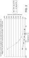
- Figure 2 shows a graph in which corrosion build-up over time (10,000 hours in this example) is plotted against pump reference temperature for the prior art pump.
- a first line shows build-up at the faces of the rotor and stator of a middle pumping stage along the flow path 56 and a second line shows build-up at the faces of the rotor and stator of a final pumping stage along the flow path 56.
- the middle pumping stage in this example is the 3 rd stage.
- Corrosive build-up is measured in microns and temperature is measured in degrees centigrade.
- the temperature used in the graph is a pump reference temperature taken at the final pumping stage.
- the temperature of the middle pumping stage is less than that shown in the graph but for simplicity has not been shown.
- the pump reference temperature increases during operation and the increase is dependent on a number of factors such as the type of fluid which is pumped and the work exerted by the pump.
- the material from which the pumping mechanism is made is relatively non-corrosion resistant.
- An example of such a material is SG iron. It will be seen from Figure 2 that corrosive build-up of the final stage is considerably greater than that of the middle pumping stage, particularly when the pump reference temperature is at 200°C. At this reference temperature, corrosive build-up at the final stage is just lower than 400 ⁇ m, whereas at the middle stage, build-up is only just higher than 50 ⁇ m.
- Figure 3 shows an equivalent graph as shown in Figure 2 , except in this analysis the material from which the pump is made is relatively corrosion resistant.
- An example of such a material is Ni-rich SG iron.
- corrosive build-up at both the middle and final pumping stages is reduced, but build-up at the final pumping stage has been reduced by around 300 ⁇ m to just lower than 100 ⁇ m whereas build-up at the middle pumping stage has been reduced by only around 30 ⁇ m to around 20 ⁇ m.
- the pressure of fluid along the flow path 56 increases from the inlet 58 to the outlet 60 as fluid is compressed by each pumping stage 54, typically with the compression ratio increasing from one pumping stage to the next pumping stage along the flow path.
- the temperature of the fluid and the pumping mechanism also increases along the flow path.
- the fluid being pumped comprises a corrosive agent, such as fluorine
- a corrosive agent such as fluorine
- the amount of corrosion caused to the pumping mechanism 52 increases along the flow path 56 as temperature and pressure increase.
- Increased pressure increases the amount of corrosive molecules available for corroding the pumping mechanism and increased temperature increases corrosive reaction. Therefore, corrosive build-up is greater at the final pumping stage than at the middle pumping stage. Accordingly, pump failure occurs because of the reduction in running clearance at the final stage of the pumping mechanism where build-up is greatest. Whilst corrosion resistance can be increased as shown in Figure 3 , pump failure often occurs at the final stage of the pumping mechanism.
- the pumping mechanism comprises a first section 24 and a second section 26.
- the second section 26 is downstream of the first section 24.
- the temperature and pressure of the downstream section 26 is greater than the temperature and pressure of the upstream section 24. Therefore, when pumping a corrosive fluid, corrosion of section 24 is less than corrosion of section 26.
- the first section 24 is required to be less resistant to corrosion than the second section 26.
- the first section 24 can therefore be made from a material which is relatively less expensive than the material of the second section.
- the first section 24 and the second section 26 comprise a respective plurality of pumping stages 14.
- the first section is adjacent to the second section along the fluid flow path.
- the first section comprises 1 st , 2 nd and 3 rd pumping stages whilst the second section 26 comprises 4 th and 5 th pumping stages.
- one of the first and the second sections may comprise a single pumping stage.
- the first section may comprise 1 st to 4 th pumping stages whilst the second section may comprise the 5 th pumping stage.
- stages 1 to 4 may be manufactured from a material which is less corrosion resistant.
- the first section may comprise the 1 st pumping stage and the second section may comprise the 2 nd to 5 th pumping stages.
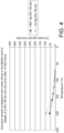
- Figure 4 A graph equivalent to the graphs shown in Figures 2 and 3 is shown in Figure 4 , which plots corrosive build-up against pump reference temperature for the pump shown in Figure 1 .
- Figure 4 shows at 200°C that corrosive build-up at the final stage of the pumping mechanism has been reduced from around 400 ⁇ m as shown in Figure 2 to just lower than 100 ⁇ m as is the case with a corrosion resistant pump according to Figure 3 .
- corrosive build-up at the middle, or 3 rd , stage is the same as that shown in Figure 2 for a non-corrosion resistant pump.
- the corrosive build-up of the middle stage is around 50 ⁇ m which is less than that of the final stage even though the middle stage is made from a non-corrosion resistant material (e.g. SG iron) and the final stage is made from a corrosion resistant material (e.g. Ni-rich iron). Therefore, there is no benefit to be gained from making both the first section and the second section of a pumping mechanism from a corrosion resistant material and doing so would unnecessarily add to the cost of a pump.
- a non-corrosion resistant material e.g. SG iron
- a corrosion resistant material e.g. Ni-rich iron
- Materials should be selected for the first and second sections so that the build-up of corrosive deposits at the first section is less than or equal to the build-up of corrosive deposits at the second section.
- the components of said pumping stages are fabricated from selected materials such that the build-up of corrosion deposits in each stage during pumping of corrosive gas is generally equal one stage to another stage. In this way, the materials for the various pumping stages can be selected in a cost efficient manner whilst maintaining acceptable resistance to corrosion.
- the rotor R and stator S of each pumping stage 14 of the second section 26 is made from a Nickel rich iron, whilst the rotor R and stator S of each pumping stage 14 of the first section 24 is made from an SG (spheroidal graphite) iron.
- Nickel is resistant to fluorine but if the fluid being pumped contains other corrosive agents it would be desirable to select an appropriately resistant material.
- the first section of the pumping mechanism may be made from materials other than SG iron.
- the first section may be made from a corrosion resistant material for instance NI-rich SG iron, whilst the second section may be made from a more corrosion resistant material such as cast stainless steel or nickel alloy.
- Figure 5 shows three examples of both SG iron and Ni-rich SG iron. It is preferable to select materials for the first and second section with similar linear expansion coefficients.
- Ni-res D-5S is a preferred corrosion resistant material as its linear expansion coefficient is 12.6 m/mK which is similar to the coefficient of SG iron of 12.5 m/mK.
- Ni-rich SG iron material which exhibits good corrosion resistant properties and also good strength and stiffness in high temperature conditions are shown in Figure 6 .
- the Nickel content is relatively high between 24 % and 32 % by weight.
- the same or similar material is used for the rotor R and stator S in each section to avoid problems associated with having components of different thermal expansion coefficients.
- the vacuum pump 10 is shown in simplified form in Figure 1 .
- the vacuum pump comprises a claw type pumping mechanism or roots type pumping mechanism, particular in which running clearance between components of the pumping mechanism is required to be small to increase efficiency.
Landscapes
- Engineering & Computer Science (AREA)
- Mechanical Engineering (AREA)
- General Engineering & Computer Science (AREA)
- Applications Or Details Of Rotary Compressors (AREA)
- Structures Of Non-Positive Displacement Pumps (AREA)
- Compressors, Vaccum Pumps And Other Relevant Systems (AREA)
Claims (6)
- Pompe à vide sèche (10) pour pomper un liquide corrosif, la pompe comprenant : un mécanisme de pompage sec (12) comprenant une pluralité d'étages de pompage (14) le long d'un trajet d'écoulement de liquide (16) entre une entrée (18) de liquide à vide poussé et une sortie (20) de liquide à faible vide, chacun desdits étages de pompage (14) comprenant un stator (S) et un rotor (R), dans laquelle les étages de pompage comprennent un mécanisme de pompage Roots ou un mécanisme de pompage à griffe, caractérisée en ce que le rotor et le stator d'un étage de pompage au niveau d'une première section (24) dudit trajet d'écoulement sont formés en un premier matériau et le rotor et le stator d'un étage de pompage au niveau d'une deuxième section (26) dudit trajet d'écoulement, en aval de ladite première section, sont formés d'un deuxième matériau, le premier et le deuxième matériaux étant configurés de sorte que l'accumulation de dépôts de corrosion à chaque étage respectif de la pompe soit généralement identique, d'un étage à l'autre, pendant le fonctionnement de la pompe.
- Pompe à vide selon la revendication 1, dans laquelle le premier matériau est du fer à graphite sphéroïdal.
- Pompe à vide selon la revendication 1 ou 2, dans laquelle le deuxième matériau est l'un du groupe de fer au graphite sphéroïde riche en nickel, d'acier inoxydable moulé, d'alliage de nickel et de Ni-res DSS.
- Pompe à vide selon l'une quelconque des revendications précédentes, dans laquelle les matériaux respectifs de la première section (24) et de la deuxième section (26) sont tels que l'accumulation de dépôts corrosifs au niveau de la première section est inférieure ou égale à l'accumulation de dépôts corrosifs au niveau de la deuxième section.
- Pompe à vide selon l'une quelconque des revendications précédentes, dans laquelle ladite première section (24) et ladite deuxième section (26) sont définies par une pluralité respective desdits étages de pompage.
- Pompe à vide selon l'une quelconque des revendications précédentes, dans laquelle ladite première section (24) est adjacente à ladite deuxième section (26) le long dudit trajet d'écoulement de liquide.
Applications Claiming Priority (2)
| Application Number | Priority Date | Filing Date | Title |
|---|---|---|---|
| GBGB0907298.4A GB0907298D0 (en) | 2009-04-29 | 2009-04-29 | Vacuum pump |
| PCT/GB2010/050572 WO2010125368A2 (fr) | 2009-04-29 | 2010-03-31 | Pompe à vide |
Publications (2)
| Publication Number | Publication Date |
|---|---|
| EP2425137A2 EP2425137A2 (fr) | 2012-03-07 |
| EP2425137B1 true EP2425137B1 (fr) | 2024-10-23 |
Family
ID=40791933
Family Applications (1)
| Application Number | Title | Priority Date | Filing Date |
|---|---|---|---|
| EP10712149.3A Active EP2425137B1 (fr) | 2009-04-29 | 2010-03-31 | Pompe à vide |
Country Status (9)
| Country | Link |
|---|---|
| US (1) | US20120045322A1 (fr) |
| EP (1) | EP2425137B1 (fr) |
| JP (1) | JP5636042B2 (fr) |
| KR (2) | KR20120007014A (fr) |
| CN (1) | CN102414449B (fr) |
| BR (1) | BRPI1009368A2 (fr) |
| GB (1) | GB0907298D0 (fr) |
| TW (1) | TWI489043B (fr) |
| WO (1) | WO2010125368A2 (fr) |
Families Citing this family (2)
| Publication number | Priority date | Publication date | Assignee | Title |
|---|---|---|---|---|
| JP2014001668A (ja) * | 2012-06-18 | 2014-01-09 | Toshiba Corp | ルーツポンプ |
| FR3051852B1 (fr) * | 2016-05-24 | 2018-06-15 | Pfeiffer Vacuum | Stator, arbre rotatif, pompe a vide de type seche et procedes de fabrication associes |
Family Cites Families (12)
| Publication number | Priority date | Publication date | Assignee | Title |
|---|---|---|---|---|
| DE3710782A1 (de) * | 1987-03-31 | 1988-10-20 | Vacuubrand Gmbh & Co | Verfahren und vorrichtung zum abpumpen von daempfen und/oder dampfhaltigen gemischen und/oder gas-dampf-gemischen oder dgl. medien |
| GB9604486D0 (en) * | 1996-03-01 | 1996-05-01 | Boc Group Plc | Improvements in vacuum pumps |
| DE19745615A1 (de) * | 1997-10-10 | 1999-04-15 | Leybold Vakuum Gmbh | Schraubenvakuumpumpe mit Rotoren |
| WO1999049220A1 (fr) * | 1998-03-23 | 1999-09-30 | Taiko Kikai Industries Co., Ltd. | Pompe d'aspiration de matieres seches |
| CN1399074A (zh) * | 2001-07-27 | 2003-02-26 | 大晃机械工业株式会社 | 干式真空泵 |
| JP4007130B2 (ja) * | 2002-09-10 | 2007-11-14 | 株式会社豊田自動織機 | 真空ポンプ |
| GB0223767D0 (en) * | 2002-10-14 | 2002-11-20 | Boc Group Plc | Pump cleaning |
| WO2004083643A1 (fr) * | 2003-03-19 | 2004-09-30 | Ebara Corporation | Pompe volumetrique a vide |
| JP2005098210A (ja) * | 2003-09-25 | 2005-04-14 | Aisin Seiki Co Ltd | 多段ドライポンプ |
| GB0609306D0 (en) * | 2006-05-11 | 2006-06-21 | Boc Group Plc | Vacuum pump |
| GB2440944B (en) * | 2006-08-11 | 2011-10-12 | Itt Mfg Enterprises Inc | Rotary lobe pump |
| GB0705971D0 (en) * | 2007-03-28 | 2007-05-09 | Boc Group Plc | Vacuum pump |
-
2009
- 2009-04-29 GB GBGB0907298.4A patent/GB0907298D0/en not_active Ceased
-
2010
- 2010-03-31 KR KR1020117025564A patent/KR20120007014A/ko not_active Ceased
- 2010-03-31 WO PCT/GB2010/050572 patent/WO2010125368A2/fr not_active Ceased
- 2010-03-31 KR KR1020177014638A patent/KR20170063990A/ko not_active Ceased
- 2010-03-31 CN CN201080018922.5A patent/CN102414449B/zh active Active
- 2010-03-31 BR BRPI1009368A patent/BRPI1009368A2/pt not_active Application Discontinuation
- 2010-03-31 JP JP2012507816A patent/JP5636042B2/ja active Active
- 2010-03-31 EP EP10712149.3A patent/EP2425137B1/fr active Active
- 2010-03-31 US US13/263,947 patent/US20120045322A1/en not_active Abandoned
- 2010-04-06 TW TW099110635A patent/TWI489043B/zh active
Also Published As
| Publication number | Publication date |
|---|---|
| KR20120007014A (ko) | 2012-01-19 |
| CN102414449A (zh) | 2012-04-11 |
| WO2010125368A2 (fr) | 2010-11-04 |
| JP5636042B2 (ja) | 2014-12-03 |
| JP2012525534A (ja) | 2012-10-22 |
| EP2425137A2 (fr) | 2012-03-07 |
| TW201102518A (en) | 2011-01-16 |
| US20120045322A1 (en) | 2012-02-23 |
| GB0907298D0 (en) | 2009-06-10 |
| TWI489043B (zh) | 2015-06-21 |
| BRPI1009368A2 (pt) | 2016-03-08 |
| KR20170063990A (ko) | 2017-06-08 |
| CN102414449B (zh) | 2015-12-16 |
| WO2010125368A3 (fr) | 2010-12-23 |
Similar Documents
| Publication | Publication Date | Title |
|---|---|---|
| US7575422B2 (en) | Compressor unit | |
| JP5981691B2 (ja) | 傾斜機能材料を用いたジャケットインペラ及びその作製方法 | |
| EP2935896B1 (fr) | Compresseur multi-étagé et procédé pour faire fonctionner un compresseur multi-étagé | |
| JP5088610B2 (ja) | 遠心圧縮機ケーシング | |
| CN103717903B (zh) | 多级离心涡轮机 | |
| JP2005098210A (ja) | 多段ドライポンプ | |
| CN1987165A (zh) | 密封装置 | |
| JP6705742B2 (ja) | 熱遮蔽体を有する圧縮機および運転方法 | |
| JP5263562B2 (ja) | 遠心圧縮機ケーシング | |
| EP2425137B1 (fr) | Pompe à vide | |
| CN101438061A (zh) | 真空泵 | |
| KR20190039963A (ko) | 진공 펌프 로터 | |
| WO2017187137A1 (fr) | Composant de pompe à vide | |
| US12110896B2 (en) | Axial flow vacuum pump with curved rotor and stator blades | |
| JP2010522843A (ja) | 真空ポンプ | |
| EP3653881B1 (fr) | Pompe à double arbre | |
| TWM423157U (en) | Titanium alloy blades of turbo molecular vacuum pump motor |
Legal Events
| Date | Code | Title | Description |
|---|---|---|---|
| PUAI | Public reference made under article 153(3) epc to a published international application that has entered the european phase |
Free format text: ORIGINAL CODE: 0009012 |
|
| 17P | Request for examination filed |
Effective date: 20110913 |
|
| AK | Designated contracting states |
Kind code of ref document: A2 Designated state(s): AT BE BG CH CY CZ DE DK EE ES FI FR GB GR HR HU IE IS IT LI LT LU LV MC MK MT NL NO PL PT RO SE SI SK SM TR |
|
| RIN1 | Information on inventor provided before grant (corrected) |
Inventor name: OKOROAFOR, EMMANUEL, UZOMA |
|
| DAX | Request for extension of the european patent (deleted) | ||
| STAA | Information on the status of an ep patent application or granted ep patent |
Free format text: STATUS: EXAMINATION IS IN PROGRESS |
|
| 17Q | First examination report despatched |
Effective date: 20161208 |
|
| RAP1 | Party data changed (applicant data changed or rights of an application transferred) |
Owner name: EDWARDS LIMITED |
|
| GRAP | Despatch of communication of intention to grant a patent |
Free format text: ORIGINAL CODE: EPIDOSNIGR1 |
|
| STAA | Information on the status of an ep patent application or granted ep patent |
Free format text: STATUS: GRANT OF PATENT IS INTENDED |
|
| RIC1 | Information provided on ipc code assigned before grant |
Ipc: F04C 18/12 20060101AFI20190607BHEP Ipc: F04C 23/00 20060101ALI20190607BHEP Ipc: F04C 25/02 20060101ALI20190607BHEP |
|
| INTG | Intention to grant announced |
Effective date: 20190627 |
|
| GRAJ | Information related to disapproval of communication of intention to grant by the applicant or resumption of examination proceedings by the epo deleted |
Free format text: ORIGINAL CODE: EPIDOSDIGR1 |
|
| STAA | Information on the status of an ep patent application or granted ep patent |
Free format text: STATUS: EXAMINATION IS IN PROGRESS |
|
| INTC | Intention to grant announced (deleted) | ||
| GRAP | Despatch of communication of intention to grant a patent |
Free format text: ORIGINAL CODE: EPIDOSNIGR1 |
|
| STAA | Information on the status of an ep patent application or granted ep patent |
Free format text: STATUS: GRANT OF PATENT IS INTENDED |
|
| INTG | Intention to grant announced |
Effective date: 20240531 |
|
| GRAS | Grant fee paid |
Free format text: ORIGINAL CODE: EPIDOSNIGR3 |
|
| GRAA | (expected) grant |
Free format text: ORIGINAL CODE: 0009210 |
|
| STAA | Information on the status of an ep patent application or granted ep patent |
Free format text: STATUS: THE PATENT HAS BEEN GRANTED |
|
| AK | Designated contracting states |
Kind code of ref document: B1 Designated state(s): AT BE BG CH CY CZ DE DK EE ES FI FR GB GR HR HU IE IS IT LI LT LU LV MC MK MT NL NO PL PT RO SE SI SK SM TR |
|
| P01 | Opt-out of the competence of the unified patent court (upc) registered |
Free format text: CASE NUMBER: APP_51919/2024 Effective date: 20240916 |
|
| REG | Reference to a national code |
Ref country code: GB Ref legal event code: FG4D |
|
| REG | Reference to a national code |
Ref country code: CH Ref legal event code: EP |
|
| REG | Reference to a national code |
Ref country code: DE Ref legal event code: R096 Ref document number: 602010069543 Country of ref document: DE |
|
| REG | Reference to a national code |
Ref country code: IE Ref legal event code: FG4D |
|
| REG | Reference to a national code |
Ref country code: LT Ref legal event code: MG9D |
|
| REG | Reference to a national code |
Ref country code: NL Ref legal event code: MP Effective date: 20241023 |
|
| REG | Reference to a national code |
Ref country code: AT Ref legal event code: MK05 Ref document number: 1735033 Country of ref document: AT Kind code of ref document: T Effective date: 20241023 |
|
| PG25 | Lapsed in a contracting state [announced via postgrant information from national office to epo] |
Ref country code: NL Free format text: LAPSE BECAUSE OF FAILURE TO SUBMIT A TRANSLATION OF THE DESCRIPTION OR TO PAY THE FEE WITHIN THE PRESCRIBED TIME-LIMIT Effective date: 20241023 |
|
| PG25 | Lapsed in a contracting state [announced via postgrant information from national office to epo] |
Ref country code: NL Free format text: LAPSE BECAUSE OF FAILURE TO SUBMIT A TRANSLATION OF THE DESCRIPTION OR TO PAY THE FEE WITHIN THE PRESCRIBED TIME-LIMIT Effective date: 20241023 |
|
| PG25 | Lapsed in a contracting state [announced via postgrant information from national office to epo] |
Ref country code: PT Free format text: LAPSE BECAUSE OF FAILURE TO SUBMIT A TRANSLATION OF THE DESCRIPTION OR TO PAY THE FEE WITHIN THE PRESCRIBED TIME-LIMIT Effective date: 20250224 Ref country code: IS Free format text: LAPSE BECAUSE OF FAILURE TO SUBMIT A TRANSLATION OF THE DESCRIPTION OR TO PAY THE FEE WITHIN THE PRESCRIBED TIME-LIMIT Effective date: 20250223 Ref country code: HR Free format text: LAPSE BECAUSE OF FAILURE TO SUBMIT A TRANSLATION OF THE DESCRIPTION OR TO PAY THE FEE WITHIN THE PRESCRIBED TIME-LIMIT Effective date: 20241023 |
|
| PGFP | Annual fee paid to national office [announced via postgrant information from national office to epo] |
Ref country code: DE Payment date: 20250327 Year of fee payment: 16 |
|
| PG25 | Lapsed in a contracting state [announced via postgrant information from national office to epo] |
Ref country code: FI Free format text: LAPSE BECAUSE OF FAILURE TO SUBMIT A TRANSLATION OF THE DESCRIPTION OR TO PAY THE FEE WITHIN THE PRESCRIBED TIME-LIMIT Effective date: 20241023 |
|
| PG25 | Lapsed in a contracting state [announced via postgrant information from national office to epo] |
Ref country code: BG Free format text: LAPSE BECAUSE OF FAILURE TO SUBMIT A TRANSLATION OF THE DESCRIPTION OR TO PAY THE FEE WITHIN THE PRESCRIBED TIME-LIMIT Effective date: 20241023 |
|
| PG25 | Lapsed in a contracting state [announced via postgrant information from national office to epo] |
Ref country code: ES Free format text: LAPSE BECAUSE OF FAILURE TO SUBMIT A TRANSLATION OF THE DESCRIPTION OR TO PAY THE FEE WITHIN THE PRESCRIBED TIME-LIMIT Effective date: 20241023 |
|
| PGFP | Annual fee paid to national office [announced via postgrant information from national office to epo] |
Ref country code: IE Payment date: 20250327 Year of fee payment: 16 |
|
| PG25 | Lapsed in a contracting state [announced via postgrant information from national office to epo] |
Ref country code: NO Free format text: LAPSE BECAUSE OF FAILURE TO SUBMIT A TRANSLATION OF THE DESCRIPTION OR TO PAY THE FEE WITHIN THE PRESCRIBED TIME-LIMIT Effective date: 20250123 |
|
| PG25 | Lapsed in a contracting state [announced via postgrant information from national office to epo] |
Ref country code: LV Free format text: LAPSE BECAUSE OF FAILURE TO SUBMIT A TRANSLATION OF THE DESCRIPTION OR TO PAY THE FEE WITHIN THE PRESCRIBED TIME-LIMIT Effective date: 20241023 Ref country code: AT Free format text: LAPSE BECAUSE OF FAILURE TO SUBMIT A TRANSLATION OF THE DESCRIPTION OR TO PAY THE FEE WITHIN THE PRESCRIBED TIME-LIMIT Effective date: 20241023 Ref country code: GR Free format text: LAPSE BECAUSE OF FAILURE TO SUBMIT A TRANSLATION OF THE DESCRIPTION OR TO PAY THE FEE WITHIN THE PRESCRIBED TIME-LIMIT Effective date: 20250124 |
|
| PG25 | Lapsed in a contracting state [announced via postgrant information from national office to epo] |
Ref country code: PL Free format text: LAPSE BECAUSE OF FAILURE TO SUBMIT A TRANSLATION OF THE DESCRIPTION OR TO PAY THE FEE WITHIN THE PRESCRIBED TIME-LIMIT Effective date: 20241023 |
|
| PGFP | Annual fee paid to national office [announced via postgrant information from national office to epo] |
Ref country code: FR Payment date: 20250325 Year of fee payment: 16 |
|
| PGFP | Annual fee paid to national office [announced via postgrant information from national office to epo] |
Ref country code: IT Payment date: 20250319 Year of fee payment: 16 Ref country code: GB Payment date: 20250327 Year of fee payment: 16 |
|
| PG25 | Lapsed in a contracting state [announced via postgrant information from national office to epo] |
Ref country code: SM Free format text: LAPSE BECAUSE OF FAILURE TO SUBMIT A TRANSLATION OF THE DESCRIPTION OR TO PAY THE FEE WITHIN THE PRESCRIBED TIME-LIMIT Effective date: 20241023 |
|
| PG25 | Lapsed in a contracting state [announced via postgrant information from national office to epo] |
Ref country code: DK Free format text: LAPSE BECAUSE OF FAILURE TO SUBMIT A TRANSLATION OF THE DESCRIPTION OR TO PAY THE FEE WITHIN THE PRESCRIBED TIME-LIMIT Effective date: 20241023 |
|
| PG25 | Lapsed in a contracting state [announced via postgrant information from national office to epo] |
Ref country code: EE Free format text: LAPSE BECAUSE OF FAILURE TO SUBMIT A TRANSLATION OF THE DESCRIPTION OR TO PAY THE FEE WITHIN THE PRESCRIBED TIME-LIMIT Effective date: 20241023 |
|
| PG25 | Lapsed in a contracting state [announced via postgrant information from national office to epo] |
Ref country code: RO Free format text: LAPSE BECAUSE OF FAILURE TO SUBMIT A TRANSLATION OF THE DESCRIPTION OR TO PAY THE FEE WITHIN THE PRESCRIBED TIME-LIMIT Effective date: 20241023 |
|
| REG | Reference to a national code |
Ref country code: DE Ref legal event code: R097 Ref document number: 602010069543 Country of ref document: DE |
|
| PG25 | Lapsed in a contracting state [announced via postgrant information from national office to epo] |
Ref country code: SK Free format text: LAPSE BECAUSE OF FAILURE TO SUBMIT A TRANSLATION OF THE DESCRIPTION OR TO PAY THE FEE WITHIN THE PRESCRIBED TIME-LIMIT Effective date: 20241023 |
|
| PG25 | Lapsed in a contracting state [announced via postgrant information from national office to epo] |
Ref country code: CZ Free format text: LAPSE BECAUSE OF FAILURE TO SUBMIT A TRANSLATION OF THE DESCRIPTION OR TO PAY THE FEE WITHIN THE PRESCRIBED TIME-LIMIT Effective date: 20241023 |
|
| PLBE | No opposition filed within time limit |
Free format text: ORIGINAL CODE: 0009261 |
|
| STAA | Information on the status of an ep patent application or granted ep patent |
Free format text: STATUS: NO OPPOSITION FILED WITHIN TIME LIMIT |
|
| PG25 | Lapsed in a contracting state [announced via postgrant information from national office to epo] |
Ref country code: SE Free format text: LAPSE BECAUSE OF FAILURE TO SUBMIT A TRANSLATION OF THE DESCRIPTION OR TO PAY THE FEE WITHIN THE PRESCRIBED TIME-LIMIT Effective date: 20241023 |
|
| 26N | No opposition filed |
Effective date: 20250724 |
|
| PG25 | Lapsed in a contracting state [announced via postgrant information from national office to epo] |
Ref country code: MC Free format text: LAPSE BECAUSE OF FAILURE TO SUBMIT A TRANSLATION OF THE DESCRIPTION OR TO PAY THE FEE WITHIN THE PRESCRIBED TIME-LIMIT Effective date: 20241023 |
|
| REG | Reference to a national code |
Ref country code: CH Ref legal event code: H13 Free format text: ST27 STATUS EVENT CODE: U-0-0-H10-H13 (AS PROVIDED BY THE NATIONAL OFFICE) Effective date: 20251023 |
|
| PG25 | Lapsed in a contracting state [announced via postgrant information from national office to epo] |
Ref country code: LU Free format text: LAPSE BECAUSE OF NON-PAYMENT OF DUE FEES Effective date: 20250331 |