EP2425120B1 - Turbine recevant des courants bidirectionnels - Google Patents
Turbine recevant des courants bidirectionnels Download PDFInfo
- Publication number
- EP2425120B1 EP2425120B1 EP10708133.3A EP10708133A EP2425120B1 EP 2425120 B1 EP2425120 B1 EP 2425120B1 EP 10708133 A EP10708133 A EP 10708133A EP 2425120 B1 EP2425120 B1 EP 2425120B1
- Authority
- EP
- European Patent Office
- Prior art keywords
- profile
- turbine
- profile half
- flow
- impeller
- Prior art date
- Legal status (The legal status is an assumption and is not a legal conclusion. Google has not performed a legal analysis and makes no representation as to the accuracy of the status listed.)
- Not-in-force
Links
- 239000012530 fluid Substances 0.000 claims description 10
- 230000002457 bidirectional effect Effects 0.000 claims description 4
- 238000004519 manufacturing process Methods 0.000 claims description 4
- 230000007704 transition Effects 0.000 claims 1
- 210000001331 nose Anatomy 0.000 description 8
- 230000009969 flowable effect Effects 0.000 description 4
- XLYOFNOQVPJJNP-UHFFFAOYSA-N water Substances O XLYOFNOQVPJJNP-UHFFFAOYSA-N 0.000 description 4
- 238000011144 upstream manufacturing Methods 0.000 description 3
- 230000006978 adaptation Effects 0.000 description 2
- 230000001419 dependent effect Effects 0.000 description 2
- 230000000694 effects Effects 0.000 description 2
- 230000000630 rising effect Effects 0.000 description 2
- 206010034016 Paronychia Diseases 0.000 description 1
- 230000002146 bilateral effect Effects 0.000 description 1
- 230000015572 biosynthetic process Effects 0.000 description 1
- 230000000295 complement effect Effects 0.000 description 1
- 238000011161 development Methods 0.000 description 1
- 230000018109 developmental process Effects 0.000 description 1
- 230000012447 hatching Effects 0.000 description 1
- 239000007788 liquid Substances 0.000 description 1
- 230000007246 mechanism Effects 0.000 description 1
- 230000000737 periodic effect Effects 0.000 description 1
- 238000010248 power generation Methods 0.000 description 1
- 230000002265 prevention Effects 0.000 description 1
Images

Classifications
-
- F—MECHANICAL ENGINEERING; LIGHTING; HEATING; WEAPONS; BLASTING
- F03—MACHINES OR ENGINES FOR LIQUIDS; WIND, SPRING, OR WEIGHT MOTORS; PRODUCING MECHANICAL POWER OR A REACTIVE PROPULSIVE THRUST, NOT OTHERWISE PROVIDED FOR
- F03B—MACHINES OR ENGINES FOR LIQUIDS
- F03B13/00—Adaptations of machines or engines for special use; Combinations of machines or engines with driving or driven apparatus; Power stations or aggregates
- F03B13/12—Adaptations of machines or engines for special use; Combinations of machines or engines with driving or driven apparatus; Power stations or aggregates characterised by using wave or tide energy
- F03B13/14—Adaptations of machines or engines for special use; Combinations of machines or engines with driving or driven apparatus; Power stations or aggregates characterised by using wave or tide energy using wave energy
- F03B13/141—Adaptations of machines or engines for special use; Combinations of machines or engines with driving or driven apparatus; Power stations or aggregates characterised by using wave or tide energy using wave energy with a static energy collector
- F03B13/142—Adaptations of machines or engines for special use; Combinations of machines or engines with driving or driven apparatus; Power stations or aggregates characterised by using wave or tide energy using wave energy with a static energy collector which creates an oscillating water column
-
- F—MECHANICAL ENGINEERING; LIGHTING; HEATING; WEAPONS; BLASTING
- F01—MACHINES OR ENGINES IN GENERAL; ENGINE PLANTS IN GENERAL; STEAM ENGINES
- F01D—NON-POSITIVE DISPLACEMENT MACHINES OR ENGINES, e.g. STEAM TURBINES
- F01D5/00—Blades; Blade-carrying members; Heating, heat-insulating, cooling or antivibration means on the blades or the members
- F01D5/12—Blades
- F01D5/14—Form or construction
- F01D5/141—Shape, i.e. outer, aerodynamic form
-
- F—MECHANICAL ENGINEERING; LIGHTING; HEATING; WEAPONS; BLASTING
- F01—MACHINES OR ENGINES IN GENERAL; ENGINE PLANTS IN GENERAL; STEAM ENGINES
- F01D—NON-POSITIVE DISPLACEMENT MACHINES OR ENGINES, e.g. STEAM TURBINES
- F01D5/00—Blades; Blade-carrying members; Heating, heat-insulating, cooling or antivibration means on the blades or the members
- F01D5/12—Blades
- F01D5/14—Form or construction
- F01D5/148—Blades with variable camber, e.g. by ejection of fluid
-
- F—MECHANICAL ENGINEERING; LIGHTING; HEATING; WEAPONS; BLASTING
- F01—MACHINES OR ENGINES IN GENERAL; ENGINE PLANTS IN GENERAL; STEAM ENGINES
- F01D—NON-POSITIVE DISPLACEMENT MACHINES OR ENGINES, e.g. STEAM TURBINES
- F01D9/00—Stators
- F01D9/02—Nozzles; Nozzle boxes; Stator blades; Guide conduits, e.g. individual nozzles
- F01D9/04—Nozzles; Nozzle boxes; Stator blades; Guide conduits, e.g. individual nozzles forming ring or sector
- F01D9/041—Nozzles; Nozzle boxes; Stator blades; Guide conduits, e.g. individual nozzles forming ring or sector using blades
-
- F—MECHANICAL ENGINEERING; LIGHTING; HEATING; WEAPONS; BLASTING
- F03—MACHINES OR ENGINES FOR LIQUIDS; WIND, SPRING, OR WEIGHT MOTORS; PRODUCING MECHANICAL POWER OR A REACTIVE PROPULSIVE THRUST, NOT OTHERWISE PROVIDED FOR
- F03B—MACHINES OR ENGINES FOR LIQUIDS
- F03B13/00—Adaptations of machines or engines for special use; Combinations of machines or engines with driving or driven apparatus; Power stations or aggregates
- F03B13/12—Adaptations of machines or engines for special use; Combinations of machines or engines with driving or driven apparatus; Power stations or aggregates characterised by using wave or tide energy
- F03B13/14—Adaptations of machines or engines for special use; Combinations of machines or engines with driving or driven apparatus; Power stations or aggregates characterised by using wave or tide energy using wave energy
- F03B13/24—Adaptations of machines or engines for special use; Combinations of machines or engines with driving or driven apparatus; Power stations or aggregates characterised by using wave or tide energy using wave energy to produce a flow of air, e.g. to drive an air turbine
-
- F—MECHANICAL ENGINEERING; LIGHTING; HEATING; WEAPONS; BLASTING
- F05—INDEXING SCHEMES RELATING TO ENGINES OR PUMPS IN VARIOUS SUBCLASSES OF CLASSES F01-F04
- F05B—INDEXING SCHEME RELATING TO WIND, SPRING, WEIGHT, INERTIA OR LIKE MOTORS, TO MACHINES OR ENGINES FOR LIQUIDS COVERED BY SUBCLASSES F03B, F03D AND F03G
- F05B2210/00—Working fluid
- F05B2210/40—Flow geometry or direction
- F05B2210/404—Flow geometry or direction bidirectional, i.e. in opposite, alternating directions
-
- F—MECHANICAL ENGINEERING; LIGHTING; HEATING; WEAPONS; BLASTING
- F05—INDEXING SCHEMES RELATING TO ENGINES OR PUMPS IN VARIOUS SUBCLASSES OF CLASSES F01-F04
- F05B—INDEXING SCHEME RELATING TO WIND, SPRING, WEIGHT, INERTIA OR LIKE MOTORS, TO MACHINES OR ENGINES FOR LIQUIDS COVERED BY SUBCLASSES F03B, F03D AND F03G
- F05B2240/00—Components
- F05B2240/20—Rotors
- F05B2240/30—Characteristics of rotor blades, i.e. of any element transforming dynamic fluid energy to or from rotational energy and being attached to a rotor
- F05B2240/301—Cross-section characteristics
-
- F—MECHANICAL ENGINEERING; LIGHTING; HEATING; WEAPONS; BLASTING
- F05—INDEXING SCHEMES RELATING TO ENGINES OR PUMPS IN VARIOUS SUBCLASSES OF CLASSES F01-F04
- F05B—INDEXING SCHEME RELATING TO WIND, SPRING, WEIGHT, INERTIA OR LIKE MOTORS, TO MACHINES OR ENGINES FOR LIQUIDS COVERED BY SUBCLASSES F03B, F03D AND F03G
- F05B2260/00—Function
- F05B2260/96—Preventing, counteracting or reducing vibration or noise
-
- F—MECHANICAL ENGINEERING; LIGHTING; HEATING; WEAPONS; BLASTING
- F05—INDEXING SCHEMES RELATING TO ENGINES OR PUMPS IN VARIOUS SUBCLASSES OF CLASSES F01-F04
- F05D—INDEXING SCHEME FOR ASPECTS RELATING TO NON-POSITIVE-DISPLACEMENT MACHINES OR ENGINES, GAS-TURBINES OR JET-PROPULSION PLANTS
- F05D2210/00—Working fluids
- F05D2210/40—Flow geometry or direction
- F05D2210/44—Flow geometry or direction bidirectional, i.e. in opposite, alternating directions
-
- F—MECHANICAL ENGINEERING; LIGHTING; HEATING; WEAPONS; BLASTING
- F05—INDEXING SCHEMES RELATING TO ENGINES OR PUMPS IN VARIOUS SUBCLASSES OF CLASSES F01-F04
- F05D—INDEXING SCHEME FOR ASPECTS RELATING TO NON-POSITIVE-DISPLACEMENT MACHINES OR ENGINES, GAS-TURBINES OR JET-PROPULSION PLANTS
- F05D2240/00—Components
- F05D2240/20—Rotors
- F05D2240/30—Characteristics of rotor blades, i.e. of any element transforming dynamic fluid energy to or from rotational energy and being attached to a rotor
- F05D2240/301—Cross-sectional characteristics
-
- F—MECHANICAL ENGINEERING; LIGHTING; HEATING; WEAPONS; BLASTING
- F05—INDEXING SCHEMES RELATING TO ENGINES OR PUMPS IN VARIOUS SUBCLASSES OF CLASSES F01-F04
- F05D—INDEXING SCHEME FOR ASPECTS RELATING TO NON-POSITIVE-DISPLACEMENT MACHINES OR ENGINES, GAS-TURBINES OR JET-PROPULSION PLANTS
- F05D2260/00—Function
- F05D2260/96—Preventing, counteracting or reducing vibration or noise
-
- Y—GENERAL TAGGING OF NEW TECHNOLOGICAL DEVELOPMENTS; GENERAL TAGGING OF CROSS-SECTIONAL TECHNOLOGIES SPANNING OVER SEVERAL SECTIONS OF THE IPC; TECHNICAL SUBJECTS COVERED BY FORMER USPC CROSS-REFERENCE ART COLLECTIONS [XRACs] AND DIGESTS
- Y02—TECHNOLOGIES OR APPLICATIONS FOR MITIGATION OR ADAPTATION AGAINST CLIMATE CHANGE
- Y02E—REDUCTION OF GREENHOUSE GAS [GHG] EMISSIONS, RELATED TO ENERGY GENERATION, TRANSMISSION OR DISTRIBUTION
- Y02E10/00—Energy generation through renewable energy sources
- Y02E10/30—Energy from the sea, e.g. using wave energy or salinity gradient
Definitions
- the invention relates to a bidirectional turbine, which retains its direction of rotation when changing the direction of flow, preferably a Wells turbine, and a power generation plant, in particular a wave power plant comprising such a turbine.
- Bidirectionally flowable turbines with the same direction are used, for example, for energy production by wave force.
- the wave energy is usually used indirectly to drive the turbine by entering a sea wave through an underground access in a wave chamber and applied to the rising and falling water level in the wave chamber befindettess air volume with oscillating pressure fluctuations. If, for the volume of air in the wave chamber, a flow channel leading to the outside area is created, in which an air turbine is located, a generic air turbine can be operated by the air flow resulting in the flow channel.
- a typical design of a bidirectionally flowable turbine with the same direction is a Wells turbine.
- This may be formed as an axial or radial turbine and comprises one or more impellers, which preferably have a hub with turbine blades mounted thereon.
- the individual turbine blades are symmetrically applied with respect to the chord to realize a bilateral Anströmuza and have a teardrop-shaped profile course.
- the chord is typically in the plane of rotation of the impeller for axial turbines. This is exemplified in the US 5,191,225 directed.
- FIG. 1 Further embodiments for Wells turbines are the DE 32 13 810 A1 refer to.
- Disclosed is a double row arrangement of turbine blades with asymmetric profiles, wherein each one row of the turbine blades is adapted to one of the directions of flow and is formed with respect to the asymmetries mirror image of the other turbine blade row.
- a turbine stage is created that as a whole is symmetrical in order to ensure bidirectional approachability, the associated plane of symmetry having the axis of rotation as surface normal.
- the object of the invention is to design a bidirectionally flowable, co-rotating turbine, in particular a Wells turbine, in such a way that its averaged efficiency is increased and the formation of instabilities, resulting in particular from stalling, is reduced. Accordingly, the turbine should have a design that allows a noise-reduced operation.
- the object underlying the invention is solved by the features of the independent claim.
- the inventors start from the knowledge that in an associated with a wave chamber flow channel an oscillating air flow is present, which is not sinusoidal.
- One of the reasons for this are asymmetries of the overall system.
- additional components in the flow channel such as the throttle valve, the safety valve, the muffler and provided on one side or on both sides differently shaped diffusers or Confusors a deviation from the sinusoidal flow in the flow channel.
- the wave characteristic itself leads to a significant directional dependence of the flow through the flow channel.
- the waveform deviates increasingly from the periodic course - while the wave crest rises steeply.
- a short and strong pressure pulse is created which leads to a corresponding flow in the flow channel. This deviates from the characteristics of the wave coasting and the sinking of the water level in the wave chamber, producing a weaker but more uniform flow.
- an adaptation to the direction-dependent flow is made.
- the asymmetry provided according to the invention relates in this case to the aerodynamic stage as a whole, so that there is a characteristic deviating from the opposite, second flow direction for a first flow direction.
- the profile of the turbine blades of an impeller is designed so that the requirement of bidirectional Anströmuza is sufficiently well met by each turbine blade and at the same time the required asymmetry for adjusting the flow direction changed with the flow characteristic can be realized.
- the profile is divided along the chord in two profile halves. Accordingly, there are a first profile half and a second profile half with matching tread depth, which merge into one another continuously at the profile noses and which are arranged opposite to the chord.
- Both the first profile half and the second profile half is a half profile, each taken from a symmetrically shaped profile chord profile, which is adapted to the flow characteristic associated with the respective inflow direction.
- the profile half assigned to a specific inflow direction lies on the suction side of the overall profile according to the invention, on which it develops its essential aerodynamic effect.
- One criterion for adapting the suction-side profile half is the maximum flow coefficient occurring for the respective flow direction.
- the corresponding profile half is designed so that a suction occurring, full-surface stall is excluded as safe as possible.
- the intake-side thickness distribution is suitable for profile adaptation, so that the thickness, the thickness reserve and the profile nose radius are adapted to the flow characteristic for the respective flow direction.
- the profile of the turbine blades according to the invention is preferably designed so that in a outflow, that is, a flow from the shaft chamber in the direction of the outside, the suction side lying profile half the thicker profile having a lower thickness reserve.
- larger profile nose radii are preferred for this purpose. This makes use of the fact that thick profiles and large profile nose radii show an improved tear-off behavior at the typically sufficiently high Reynolds numbers for the present application.
- the suction side at the suction cycle the likelihood of the instabilities mentioned is less likely. Accordingly, slimmer profiles with larger thickness backing, resulting in less resistance, can be used. Overall, a profile is created which shows an improved detachment behavior. Furthermore, the sound level emitted by the turbine is reduced.
- the nozzle of an aerodynamically effective stage is designed asymmetrically. This is either only one on one Side of the impeller of the stage arranged vane arrangement available or exist in a two-sided vane arrangement geometrically induced differences in the degree of deflection for a matching flow.
- the distributor is adapted so that the upstream of the impeller positioned vane assembly is suitable for the maximum occurring from this flow direction flow. For a high flow velocity from one direction correspondingly high deflection angles are caused by the vane arrangement, so that the inflow angle is reduced at the turbine blades of the impeller for this direction of flow and at the same time the effective flow rate is reduced.
- a third embodiment variant of the invention relates in addition to the asymmetrical profile a non-vanishing angle of attack of the chord of the turbine blade relative to the plane of rotation of the impeller of the respective stage.
- an embodiment with a rigid fixation of the turbine blades on the hub of the impeller due to constructive simplicity is preferred. Accordingly, the selected angle of attack is fixed and serves to reduce the inflow angle for the direction of flow at higher speed peaks and to correspondingly increase the inflow angle for the opposite direction with lower maximum flow rates.
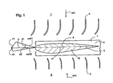
- FIG. 1 shows in schematic simplification an aerodynamically effective stage of a generic turbine as a plan view of a portion of the impeller 1.
- This includes a hub 2 with a plurality of turbine blades 3, wherein one is shown in profile in the figure.
- the components of the distributor are arranged on both sides of the impeller 1, the components of the distributor are arranged.
- Sketched is a first vane assembly 4, which is located upstream of the impeller 1 in an inflow from the first flow channel section 7. In an opposite flow direction, an inflow from the second flow channel portion 8, the second vane assembly 5 is upstream.
- first vane arrangement 4 deflects the flow more strongly than the second vane arrangement 5.
- first vane arrangement 4 is adapted for the first channel-side flow velocity vk1, which in the illustrated case is greater than the second one and / or the maximum value Channel-side flow velocity vk2 from the opposite direction. For these, the first vane assembly 4 is designed.
- FIG. 1 Another out FIG. 1 apparent asymmetry relates to the profile of the turbine blade 3 shown, which differs at least for the present section of the usual, the profile chord 17 symmetrical design.
- the bi-directional approachability must be maintained for the asymmetrically selected profile according to the invention, so that the profile consists of a first profile half 9 and a second profile half 10 which have matching profile depths, connect continuously to one another and which themselves are derived from symmetrical profiles adapted to the flow characteristic ,
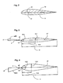
- FIG. 2 shows the first profile half 9 and the second profile half 10 with different hatchings, so that the assembly opposite to the chord 17 is illustrated. This results in a curved profile - this is clear from the course of the dashed skeleton line 18, wherein each of the two profile halves 9, 10, a separate thickness profile can be assigned.
- FIG. 3 shows the derivative of the first profile half 9. It is assumed for a given rated speed belonging to the respective flow direction, the first effective flow velocity veff1, which is composed of the first maximum fluid velocity v1 and the negative rotational velocity u vectorial. This results in a flow angle a1.
- an adapted profile which is symmetrical to the profile chord 17, is selected which is defined for a specific profile depth 11 by a thickness distribution. Characteristic of the selected thickness distribution are thickness 12.1, 12.2, thickness backing 13.1, 13.2 and profile nose radius 14.1, 14.2 for rounding the profile at the leading edge 15th
- the starting point is a moderate, first maximum fluid velocity v1.
- the resulting profile is elongated and has a small thickness 12.1, a large thickness reserve 13.1 and a small profile nose radius 14.1.
- Such an elongated one A stretched profile generates a low friction, but allows only small flow angles a1 to the occurrence of a large-scale stall.
- the first profile half 9, which is made of the in FIG. 3 is derived profile is on the suction side for the relevant direction of flow on the overall profile in FIG. 2 stated.
- FIG. 4 shows the derivative of the second profile half 10, for the in FIG. 4 shown inflow direction is suction side. It is assumed that a second maximum fluid velocity v2 from this direction, which is significantly greater than the first maximum fluid velocity v1 FIG. 3 is.
- a second effective flow velocity veff2 results, which is greater in magnitude than veff1 and leads to a larger flow angle a2.
- FIG. 4 sketched profile adapted and pointing at one opposite FIG. 3 constant profile depth 11 a greater thickness 12.2, a smaller thickness reserve 13.2 and a larger profile nose radius 14.2.
- a profile geometry adapted in this way. Consequently, from this profile, the second profile half 10 is derived, which then for the in FIG. 4 present inflow direction is present on the suction side of the overall profile - this is in FIG. 2 shown.
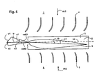
- FIG. 5 shows a further embodiment variant of the invention with a caused by an inclination of the turbine blades 3 on the hub 2 of the impeller 1 additional asymmetry.
- This measure is combined with an asymmetrically designed distributor and a profile for the chord 17 asymmetric profile for the turbine blade 3.
- the angle of attack 19 between the chord 17 and the rotation plane 16, which is preferably selected smaller than 5 ° the flow angle a1 at the same time Increase in the Angle of flow a2 additionally reduced.
- vk1 which is greater than the second channel-side flow velocity vk2.
- FIG. 6 shows a sketch of a turbine according to the invention with two aerodynamically effective stages.
- Sketched is a first impeller 1.1 with a first hub 2.1, which carries a plurality of turbine blades, with only a first turbine blade 3.1 is shown in profile section.
- a second impeller 1.2 is shown with a second hub 2.2 and a second turbine blade 3.2.
- the two wheels 1.1 and 1.2 are rigidly interconnected and serve to drive an electric generator (not shown).
- a two-stage or multi-stage constructed generic turbine is therefore advantageous because the maximum pressure reduction for safe prevention of transonic flow in the wake is limited; two or more stages therefore serve to increase efficiency.
- a direction-dependent flow characteristic it should be noted with two or more stages that an additional swirl component is present in the flow after each of the wheels due to the rotor effect. It is therefore preferred between the first impeller 1.1 and the second impeller 1.2 an additional, middle vane assembly 6 is used, which serves to return the swirl.
- the influence of the impeller 1.1 after passing through the middle vane arrangement 6 is compensated.
- the first aerodynamically effective stage 21, the first impeller 1.1 and the first vane assembly 4th and the second vane assembly 5 calculated.
- the second aerodynamically effective stage 22 includes the second impeller 2.2, the first vane assembly 4, and the second vane assembly 5, respectively.
- the first vane assembly 4 is formed asymmetrically to the second vane assembly 5, that is, it generates a different degree of deflection for a matching flow.
- a turbine blade 3 which is articulated rotatably on the hub 2
- the break-off characteristic is further improved by allowing a passive pitch setting, in particular for critical, high flow coefficients, a certain angle of incidence of the turbine blade to the plane of rotation and thus a reduced flow angle.
- stops for rotational movements may be provided, which are arranged asymmetrically to the plane of rotation, so that in one direction, a further swinging of the turbine blade is possible.
- the inventive measures can be combined with a flexible or partially flexible turbine blade.
Landscapes
- Engineering & Computer Science (AREA)
- Mechanical Engineering (AREA)
- General Engineering & Computer Science (AREA)
- Chemical & Material Sciences (AREA)
- Combustion & Propulsion (AREA)
- Physics & Mathematics (AREA)
- Fluid Mechanics (AREA)
- Turbine Rotor Nozzle Sealing (AREA)
Claims (10)
- Turbine pour une rotation dans le même sens avec une arrivée de flux bidirectionnelle, comprenant1.1 au moins un étage ayant un effet aérodynamique avec au moins une roue (1) comprenant au moins une pale de turbine (3),
caractérisée en ce que1.2 l'étage ayant un effet aérodynamique dans son ensemble est construit de façon asymétrique par rapport au sens d'arrivée du flux, en cela que le profilé d'au moins une partie de la pale de turbine (3) se compose d'une première moitié de profilé (9) et d'une deuxième moitié de profilé (9) dont la profondeur de profilé coïncide, qui sont disposées face à face par rapport à la corde du profilé (17) et qui présentent sur le bord d'attaque (15) une transition continue, la première moitié de profilé (9) et la deuxième moitié de profilé (10) présentant une forme de profilé différente l'une de l'autre. - Turbine selon la revendication 1, caractérisée en ce que la première moitié de profilé (9) et la deuxième moitié de profilé (10) présentent une répartition de l'épaisseur différente.
- Turbine selon la revendication 2, caractérisée en ce que la première moitié de profilé (9) et la deuxième moitié de profilé (10) présentent des épaisseurs (12.1, 12.2) différentes.
- Turbine selon l'une des revendications 2 ou 3, caractérisée en ce que la première moitié de profilé (9) et la deuxième moitié de profilé (10) présentent des positions d'épaisseur maximale (13.1, 13.2) différentes.
- Turbine selon l'une des revendications 2 à 4, caractérisée en ce que la première moitié de profilé (9) et la deuxième moitié de profilé (10) présentent des rayons de bord de profilé (14.1, 14.2) différents sur le bord d'attaque (15).
- Turbine selon l'une des revendications 1 à 5, comprenant 6.1 une première disposition d'aubes directrices (5) et une deuxième disposition d'aubes directrices (6), la roue (1) étant placée entre la première disposition d'aubes directrices (5) et la deuxième disposition d'aubes directrices (6) et la première disposition d'aubes directrices (5) étant construite de façon asymétrique par rapport à la deuxième disposition d'aubes directrices (6).
- Turbine selon la revendication 6, caractérisée en ce que la première disposition d'aubes directrices (5) produit, dans les mêmes conditions d'arrivée du flux, une déviation du flux différente de la deuxième disposition d'aubes directrices (6).
- Turbine selon l'une des revendications précédentes, dans laquelle la roue (1) comprend plusieurs pales de turbine (3), caractérisée en ce que les pales de turbine (3) sont fixées à la roue (1) selon un angle d'incidence (19).
- Installation de génération d'énergie comprenant9.1 une turbine selon l'une des revendications 1 à 8 pour laquelle la première vitesse maximale de fluide (v1) dans un premier sens de circulation est différente de la deuxième vitesse maximale de fluide (v2) dans le deuxième sens de circulation opposé et la différence entre la première moitié de profilé (9) et la deuxième moitié de profilé (9) est adaptée à la différence des vitesses maximales de fluide (v1, v2).
- Installation de génération d'énergie selon la revendication 9, caractérisée en ce que l'installation de génération d'énergie sert à exploiter l'énergie des vagues.
Applications Claiming Priority (2)
| Application Number | Priority Date | Filing Date | Title |
|---|---|---|---|
| DE102009018924A DE102009018924A1 (de) | 2009-04-28 | 2009-04-28 | Bidirektional anströmbare Turbine |
| PCT/EP2010/001439 WO2010124762A2 (fr) | 2009-04-28 | 2010-03-09 | Turbine recevant des courants bidirectionnels |
Publications (2)
| Publication Number | Publication Date |
|---|---|
| EP2425120A2 EP2425120A2 (fr) | 2012-03-07 |
| EP2425120B1 true EP2425120B1 (fr) | 2013-05-08 |
Family
ID=42813628
Family Applications (1)
| Application Number | Title | Priority Date | Filing Date |
|---|---|---|---|
| EP10708133.3A Not-in-force EP2425120B1 (fr) | 2009-04-28 | 2010-03-09 | Turbine recevant des courants bidirectionnels |
Country Status (5)
| Country | Link |
|---|---|
| EP (1) | EP2425120B1 (fr) |
| DE (1) | DE102009018924A1 (fr) |
| ES (1) | ES2410375T3 (fr) |
| PT (1) | PT2425120E (fr) |
| WO (1) | WO2010124762A2 (fr) |
Cited By (1)
| Publication number | Priority date | Publication date | Assignee | Title |
|---|---|---|---|---|
| US12078145B2 (en) | 2014-08-05 | 2024-09-03 | Biomerenewables Inc. | Fluidic turbine structure |
Families Citing this family (3)
| Publication number | Priority date | Publication date | Assignee | Title |
|---|---|---|---|---|
| EP3608505B1 (fr) * | 2018-08-08 | 2021-06-23 | General Electric Company | Turbine intégrant des clôtures de paroi terminale |
| IT202100002240A1 (it) | 2021-02-02 | 2022-08-02 | Gen Electric | Motore a turbine con palette a flusso trasversale ridotto |
| WO2022175870A1 (fr) * | 2021-02-22 | 2022-08-25 | Howden Axial Fans Aps | Aubes directrices pour une turbomachine complètement réversible |
Family Cites Families (7)
| Publication number | Priority date | Publication date | Assignee | Title |
|---|---|---|---|---|
| US3912938A (en) * | 1974-01-25 | 1975-10-14 | Gregory D Filipenco | Electrical stations operated by waves |
| GB1574379A (en) | 1977-08-24 | 1980-09-03 | English Electric Co Ltd | Turbines and like rotary machines |
| CH659851A5 (de) | 1981-06-05 | 1987-02-27 | Escher Wyss Ag | Turbine. |
| JPS63219801A (ja) | 1987-03-06 | 1988-09-13 | Saga Univ | 自己可変ピツチ翼を有する波力発電用タ−ビン |
| GB9022713D0 (en) | 1990-10-18 | 1990-11-28 | Wells Alan A | Wave power apparatus |
| AUPO361396A0 (en) * | 1996-11-14 | 1996-12-12 | Energetech Australia Pty Limited | Parabolic wave focuser & double ended aerofoil turbine |
| US20070231148A1 (en) * | 2006-04-03 | 2007-10-04 | Lehoczky Kalman N | Reversing free flow propeller turbine |
-
2009
- 2009-04-28 DE DE102009018924A patent/DE102009018924A1/de not_active Withdrawn
-
2010
- 2010-03-09 ES ES10708133T patent/ES2410375T3/es active Active
- 2010-03-09 WO PCT/EP2010/001439 patent/WO2010124762A2/fr not_active Ceased
- 2010-03-09 PT PT107081333T patent/PT2425120E/pt unknown
- 2010-03-09 EP EP10708133.3A patent/EP2425120B1/fr not_active Not-in-force
Cited By (1)
| Publication number | Priority date | Publication date | Assignee | Title |
|---|---|---|---|---|
| US12078145B2 (en) | 2014-08-05 | 2024-09-03 | Biomerenewables Inc. | Fluidic turbine structure |
Also Published As
| Publication number | Publication date |
|---|---|
| PT2425120E (pt) | 2013-06-04 |
| EP2425120A2 (fr) | 2012-03-07 |
| DE102009018924A1 (de) | 2010-11-04 |
| WO2010124762A2 (fr) | 2010-11-04 |
| WO2010124762A3 (fr) | 2010-12-23 |
| ES2410375T3 (es) | 2013-07-01 |
Similar Documents
| Publication | Publication Date | Title |
|---|---|---|
| DE10347802B3 (de) | Rotorblatt für eine Windkraftanlage | |
| EP2623793B1 (fr) | Turbomachine avec grille d'aubes | |
| DE102012206105A1 (de) | Impeller und strömungsmaschine mit dem impeller | |
| DE102009025857A1 (de) | Windmaschinenrotorflügel-Grundrisse mit verdrehten und sich verjüngenden Spitzen | |
| WO2010007137A1 (fr) | Turbomachine axiale à pertes par jeu réduites | |
| EP2425120B1 (fr) | Turbine recevant des courants bidirectionnels | |
| EP3066337B1 (fr) | Pale de rotor d'une éolienne et éolienne | |
| EP4083433A1 (fr) | Ventilateur et aubes de ventilateur | |
| EP1244872A1 (fr) | Pale de rotor pour eolienne | |
| EP3147499B1 (fr) | Pale de rotor a profil optimise contre le bruit et procede de fabrication d'une pale de rotor | |
| EP2978967B1 (fr) | Pale de rotor munie d'une penne pour éolienne | |
| DE202012005356U1 (de) | Rotorblatt für Windturbinen mit Profilen in Tandemanordnung | |
| EP2232058B1 (fr) | Turbine à air pour centrale houlomotrice | |
| DE102009057449B3 (de) | Turbinenblatt für eine bidirektional anströmbare Wasserturbine | |
| DE3148995A1 (de) | Axialturbine | |
| WO2010000229A2 (fr) | Grille d'aubes pour une turbomachine et turbomachine comportant une telle grille | |
| EP2636892A2 (fr) | Installation éolienne et procédé de production d'énergie rotative par le vent | |
| CH714302A2 (de) | Aerodynamisch optimiertes Rotorblatt. | |
| EP3954892A2 (fr) | Pale de rotor pour une éolienne, rotor pour une éolienne, construction et éolienne | |
| DE102008051297B3 (de) | Rotorblatt einer Windkraftanlage | |
| WO2021004853A1 (fr) | Pale de rotor pour éolienne et éolienne | |
| DE102013006203B4 (de) | Rotorblatt für eine Windkraftanlage | |
| WO2012020041A1 (fr) | Dispositif permettant de convertir l'énergie d'un fluide en écoulement | |
| EP3686423B1 (fr) | Pale de rotor pour une éolienne | |
| DE102017107465A1 (de) | Profilkörper zum Erzeugen von dynamischem Auftrieb, Rotorblatt mit dem Profilkörper und Verfahren zum Profilieren des Profilkörpers |
Legal Events
| Date | Code | Title | Description |
|---|---|---|---|
| PUAI | Public reference made under article 153(3) epc to a published international application that has entered the european phase |
Free format text: ORIGINAL CODE: 0009012 |
|
| 17P | Request for examination filed |
Effective date: 20110209 |
|
| AK | Designated contracting states |
Kind code of ref document: A2 Designated state(s): AT BE BG CH CY CZ DE DK EE ES FI FR GB GR HR HU IE IS IT LI LT LU LV MC MK MT NL NO PL PT RO SE SI SK SM TR |
|
| RIN1 | Information on inventor provided before grant (corrected) |
Inventor name: WEILEPP, JOCHEN Inventor name: ARLITT, RAPHAEL |
|
| DAX | Request for extension of the european patent (deleted) | ||
| GRAP | Despatch of communication of intention to grant a patent |
Free format text: ORIGINAL CODE: EPIDOSNIGR1 |
|
| GRAS | Grant fee paid |
Free format text: ORIGINAL CODE: EPIDOSNIGR3 |
|
| GRAA | (expected) grant |
Free format text: ORIGINAL CODE: 0009210 |
|
| AK | Designated contracting states |
Kind code of ref document: B1 Designated state(s): AT BE BG CH CY CZ DE DK EE ES FI FR GB GR HR HU IE IS IT LI LT LU LV MC MK MT NL NO PL PT RO SE SI SK SM TR |
|
| REG | Reference to a national code |
Ref country code: GB Ref legal event code: FG4D Free format text: NOT ENGLISH |
|
| REG | Reference to a national code |
Ref country code: CH Ref legal event code: EP Ref country code: AT Ref legal event code: REF Ref document number: 611231 Country of ref document: AT Kind code of ref document: T Effective date: 20130515 |
|
| REG | Reference to a national code |
Ref country code: PT Ref legal event code: SC4A Free format text: AVAILABILITY OF NATIONAL TRANSLATION Effective date: 20130528 |
|
| REG | Reference to a national code |
Ref country code: IE Ref legal event code: FG4D Free format text: LANGUAGE OF EP DOCUMENT: GERMAN |
|
| REG | Reference to a national code |
Ref country code: ES Ref legal event code: FG2A Ref document number: 2410375 Country of ref document: ES Kind code of ref document: T3 Effective date: 20130701 |
|
| REG | Reference to a national code |
Ref country code: DE Ref legal event code: R096 Ref document number: 502010003271 Country of ref document: DE Effective date: 20130704 |
|
| REG | Reference to a national code |
Ref country code: LT Ref legal event code: MG4D |
|
| REG | Reference to a national code |
Ref country code: NL Ref legal event code: VDEP Effective date: 20130508 |
|
| PG25 | Lapsed in a contracting state [announced via postgrant information from national office to epo] |
Ref country code: NO Free format text: LAPSE BECAUSE OF FAILURE TO SUBMIT A TRANSLATION OF THE DESCRIPTION OR TO PAY THE FEE WITHIN THE PRESCRIBED TIME-LIMIT Effective date: 20130808 Ref country code: IS Free format text: LAPSE BECAUSE OF FAILURE TO SUBMIT A TRANSLATION OF THE DESCRIPTION OR TO PAY THE FEE WITHIN THE PRESCRIBED TIME-LIMIT Effective date: 20130908 Ref country code: GR Free format text: LAPSE BECAUSE OF FAILURE TO SUBMIT A TRANSLATION OF THE DESCRIPTION OR TO PAY THE FEE WITHIN THE PRESCRIBED TIME-LIMIT Effective date: 20130809 Ref country code: LT Free format text: LAPSE BECAUSE OF FAILURE TO SUBMIT A TRANSLATION OF THE DESCRIPTION OR TO PAY THE FEE WITHIN THE PRESCRIBED TIME-LIMIT Effective date: 20130508 Ref country code: FI Free format text: LAPSE BECAUSE OF FAILURE TO SUBMIT A TRANSLATION OF THE DESCRIPTION OR TO PAY THE FEE WITHIN THE PRESCRIBED TIME-LIMIT Effective date: 20130508 Ref country code: SI Free format text: LAPSE BECAUSE OF FAILURE TO SUBMIT A TRANSLATION OF THE DESCRIPTION OR TO PAY THE FEE WITHIN THE PRESCRIBED TIME-LIMIT Effective date: 20130508 Ref country code: SE Free format text: LAPSE BECAUSE OF FAILURE TO SUBMIT A TRANSLATION OF THE DESCRIPTION OR TO PAY THE FEE WITHIN THE PRESCRIBED TIME-LIMIT Effective date: 20130508 |
|
| PG25 | Lapsed in a contracting state [announced via postgrant information from national office to epo] |
Ref country code: PL Free format text: LAPSE BECAUSE OF FAILURE TO SUBMIT A TRANSLATION OF THE DESCRIPTION OR TO PAY THE FEE WITHIN THE PRESCRIBED TIME-LIMIT Effective date: 20130508 Ref country code: HR Free format text: LAPSE BECAUSE OF FAILURE TO SUBMIT A TRANSLATION OF THE DESCRIPTION OR TO PAY THE FEE WITHIN THE PRESCRIBED TIME-LIMIT Effective date: 20130508 Ref country code: CY Free format text: LAPSE BECAUSE OF FAILURE TO SUBMIT A TRANSLATION OF THE DESCRIPTION OR TO PAY THE FEE WITHIN THE PRESCRIBED TIME-LIMIT Effective date: 20130508 Ref country code: BG Free format text: LAPSE BECAUSE OF FAILURE TO SUBMIT A TRANSLATION OF THE DESCRIPTION OR TO PAY THE FEE WITHIN THE PRESCRIBED TIME-LIMIT Effective date: 20130808 |
|
| PG25 | Lapsed in a contracting state [announced via postgrant information from national office to epo] |
Ref country code: LV Free format text: LAPSE BECAUSE OF FAILURE TO SUBMIT A TRANSLATION OF THE DESCRIPTION OR TO PAY THE FEE WITHIN THE PRESCRIBED TIME-LIMIT Effective date: 20130508 |
|
| PG25 | Lapsed in a contracting state [announced via postgrant information from national office to epo] |
Ref country code: EE Free format text: LAPSE BECAUSE OF FAILURE TO SUBMIT A TRANSLATION OF THE DESCRIPTION OR TO PAY THE FEE WITHIN THE PRESCRIBED TIME-LIMIT Effective date: 20130508 Ref country code: CZ Free format text: LAPSE BECAUSE OF FAILURE TO SUBMIT A TRANSLATION OF THE DESCRIPTION OR TO PAY THE FEE WITHIN THE PRESCRIBED TIME-LIMIT Effective date: 20130508 Ref country code: DK Free format text: LAPSE BECAUSE OF FAILURE TO SUBMIT A TRANSLATION OF THE DESCRIPTION OR TO PAY THE FEE WITHIN THE PRESCRIBED TIME-LIMIT Effective date: 20130508 Ref country code: SK Free format text: LAPSE BECAUSE OF FAILURE TO SUBMIT A TRANSLATION OF THE DESCRIPTION OR TO PAY THE FEE WITHIN THE PRESCRIBED TIME-LIMIT Effective date: 20130508 |
|
| PG25 | Lapsed in a contracting state [announced via postgrant information from national office to epo] |
Ref country code: IT Free format text: LAPSE BECAUSE OF FAILURE TO SUBMIT A TRANSLATION OF THE DESCRIPTION OR TO PAY THE FEE WITHIN THE PRESCRIBED TIME-LIMIT Effective date: 20130508 Ref country code: RO Free format text: LAPSE BECAUSE OF FAILURE TO SUBMIT A TRANSLATION OF THE DESCRIPTION OR TO PAY THE FEE WITHIN THE PRESCRIBED TIME-LIMIT Effective date: 20130508 Ref country code: NL Free format text: LAPSE BECAUSE OF FAILURE TO SUBMIT A TRANSLATION OF THE DESCRIPTION OR TO PAY THE FEE WITHIN THE PRESCRIBED TIME-LIMIT Effective date: 20130508 |
|
| PLBE | No opposition filed within time limit |
Free format text: ORIGINAL CODE: 0009261 |
|
| STAA | Information on the status of an ep patent application or granted ep patent |
Free format text: STATUS: NO OPPOSITION FILED WITHIN TIME LIMIT |
|
| 26N | No opposition filed |
Effective date: 20140211 |
|
| REG | Reference to a national code |
Ref country code: DE Ref legal event code: R097 Ref document number: 502010003271 Country of ref document: DE Effective date: 20140211 |
|
| PG25 | Lapsed in a contracting state [announced via postgrant information from national office to epo] |
Ref country code: LU Free format text: LAPSE BECAUSE OF FAILURE TO SUBMIT A TRANSLATION OF THE DESCRIPTION OR TO PAY THE FEE WITHIN THE PRESCRIBED TIME-LIMIT Effective date: 20140309 |
|
| REG | Reference to a national code |
Ref country code: CH Ref legal event code: PL |
|
| PG25 | Lapsed in a contracting state [announced via postgrant information from national office to epo] |
Ref country code: CH Free format text: LAPSE BECAUSE OF NON-PAYMENT OF DUE FEES Effective date: 20140331 Ref country code: LI Free format text: LAPSE BECAUSE OF NON-PAYMENT OF DUE FEES Effective date: 20140331 |
|
| PG25 | Lapsed in a contracting state [announced via postgrant information from national office to epo] |
Ref country code: MT Free format text: LAPSE BECAUSE OF FAILURE TO SUBMIT A TRANSLATION OF THE DESCRIPTION OR TO PAY THE FEE WITHIN THE PRESCRIBED TIME-LIMIT Effective date: 20130508 |
|
| REG | Reference to a national code |
Ref country code: FR Ref legal event code: PLFP Year of fee payment: 7 |
|
| PG25 | Lapsed in a contracting state [announced via postgrant information from national office to epo] |
Ref country code: SM Free format text: LAPSE BECAUSE OF FAILURE TO SUBMIT A TRANSLATION OF THE DESCRIPTION OR TO PAY THE FEE WITHIN THE PRESCRIBED TIME-LIMIT Effective date: 20130508 |
|
| REG | Reference to a national code |
Ref country code: AT Ref legal event code: MM01 Ref document number: 611231 Country of ref document: AT Kind code of ref document: T Effective date: 20150309 |
|
| PG25 | Lapsed in a contracting state [announced via postgrant information from national office to epo] |
Ref country code: MC Free format text: LAPSE BECAUSE OF FAILURE TO SUBMIT A TRANSLATION OF THE DESCRIPTION OR TO PAY THE FEE WITHIN THE PRESCRIBED TIME-LIMIT Effective date: 20130508 |
|
| PG25 | Lapsed in a contracting state [announced via postgrant information from national office to epo] |
Ref country code: HU Free format text: LAPSE BECAUSE OF FAILURE TO SUBMIT A TRANSLATION OF THE DESCRIPTION OR TO PAY THE FEE WITHIN THE PRESCRIBED TIME-LIMIT; INVALID AB INITIO Effective date: 20100309 Ref country code: TR Free format text: LAPSE BECAUSE OF FAILURE TO SUBMIT A TRANSLATION OF THE DESCRIPTION OR TO PAY THE FEE WITHIN THE PRESCRIBED TIME-LIMIT Effective date: 20130508 |
|
| PG25 | Lapsed in a contracting state [announced via postgrant information from national office to epo] |
Ref country code: AT Free format text: LAPSE BECAUSE OF NON-PAYMENT OF DUE FEES Effective date: 20150309 |
|
| REG | Reference to a national code |
Ref country code: FR Ref legal event code: PLFP Year of fee payment: 8 |
|
| PG25 | Lapsed in a contracting state [announced via postgrant information from national office to epo] |
Ref country code: BE Free format text: LAPSE BECAUSE OF NON-PAYMENT OF DUE FEES Effective date: 20140331 |
|
| REG | Reference to a national code |
Ref country code: FR Ref legal event code: PLFP Year of fee payment: 9 |
|
| PG25 | Lapsed in a contracting state [announced via postgrant information from national office to epo] |
Ref country code: MK Free format text: LAPSE BECAUSE OF FAILURE TO SUBMIT A TRANSLATION OF THE DESCRIPTION OR TO PAY THE FEE WITHIN THE PRESCRIBED TIME-LIMIT Effective date: 20130508 |
|
| PGFP | Annual fee paid to national office [announced via postgrant information from national office to epo] |
Ref country code: IE Payment date: 20200320 Year of fee payment: 11 Ref country code: PT Payment date: 20200305 Year of fee payment: 11 Ref country code: GB Payment date: 20200323 Year of fee payment: 11 Ref country code: DE Payment date: 20200320 Year of fee payment: 11 |
|
| PGFP | Annual fee paid to national office [announced via postgrant information from national office to epo] |
Ref country code: FR Payment date: 20200320 Year of fee payment: 11 |
|
| PGFP | Annual fee paid to national office [announced via postgrant information from national office to epo] |
Ref country code: ES Payment date: 20200522 Year of fee payment: 11 |
|
| REG | Reference to a national code |
Ref country code: DE Ref legal event code: R119 Ref document number: 502010003271 Country of ref document: DE |
|
| GBPC | Gb: european patent ceased through non-payment of renewal fee |
Effective date: 20210309 |
|
| PG25 | Lapsed in a contracting state [announced via postgrant information from national office to epo] |
Ref country code: PT Free format text: LAPSE BECAUSE OF NON-PAYMENT OF DUE FEES Effective date: 20210909 |
|
| PG25 | Lapsed in a contracting state [announced via postgrant information from national office to epo] |
Ref country code: FR Free format text: LAPSE BECAUSE OF NON-PAYMENT OF DUE FEES Effective date: 20210331 Ref country code: IE Free format text: LAPSE BECAUSE OF NON-PAYMENT OF DUE FEES Effective date: 20210309 Ref country code: GB Free format text: LAPSE BECAUSE OF NON-PAYMENT OF DUE FEES Effective date: 20210309 Ref country code: DE Free format text: LAPSE BECAUSE OF NON-PAYMENT OF DUE FEES Effective date: 20211001 |
|
| REG | Reference to a national code |
Ref country code: ES Ref legal event code: FD2A Effective date: 20220523 |
|
| PG25 | Lapsed in a contracting state [announced via postgrant information from national office to epo] |
Ref country code: ES Free format text: LAPSE BECAUSE OF NON-PAYMENT OF DUE FEES Effective date: 20210310 |