EP2425120B1 - Bidirectionally impingeable turbine - Google Patents
Bidirectionally impingeable turbine Download PDFInfo
- Publication number
- EP2425120B1 EP2425120B1 EP10708133.3A EP10708133A EP2425120B1 EP 2425120 B1 EP2425120 B1 EP 2425120B1 EP 10708133 A EP10708133 A EP 10708133A EP 2425120 B1 EP2425120 B1 EP 2425120B1
- Authority
- EP
- European Patent Office
- Prior art keywords
- profile
- turbine
- profile half
- flow
- impeller
- Prior art date
- Legal status (The legal status is an assumption and is not a legal conclusion. Google has not performed a legal analysis and makes no representation as to the accuracy of the status listed.)
- Not-in-force
Links
Images

Classifications
-
- F—MECHANICAL ENGINEERING; LIGHTING; HEATING; WEAPONS; BLASTING
- F03—MACHINES OR ENGINES FOR LIQUIDS; WIND, SPRING, OR WEIGHT MOTORS; PRODUCING MECHANICAL POWER OR A REACTIVE PROPULSIVE THRUST, NOT OTHERWISE PROVIDED FOR
- F03B—MACHINES OR ENGINES FOR LIQUIDS
- F03B13/00—Adaptations of machines or engines for special use; Combinations of machines or engines with driving or driven apparatus; Power stations or aggregates
- F03B13/12—Adaptations of machines or engines for special use; Combinations of machines or engines with driving or driven apparatus; Power stations or aggregates characterised by using wave or tide energy
- F03B13/14—Adaptations of machines or engines for special use; Combinations of machines or engines with driving or driven apparatus; Power stations or aggregates characterised by using wave or tide energy using wave energy
- F03B13/141—Adaptations of machines or engines for special use; Combinations of machines or engines with driving or driven apparatus; Power stations or aggregates characterised by using wave or tide energy using wave energy with a static energy collector
- F03B13/142—Adaptations of machines or engines for special use; Combinations of machines or engines with driving or driven apparatus; Power stations or aggregates characterised by using wave or tide energy using wave energy with a static energy collector which creates an oscillating water column
-
- F—MECHANICAL ENGINEERING; LIGHTING; HEATING; WEAPONS; BLASTING
- F01—MACHINES OR ENGINES IN GENERAL; ENGINE PLANTS IN GENERAL; STEAM ENGINES
- F01D—NON-POSITIVE DISPLACEMENT MACHINES OR ENGINES, e.g. STEAM TURBINES
- F01D5/00—Blades; Blade-carrying members; Heating, heat-insulating, cooling or antivibration means on the blades or the members
- F01D5/12—Blades
- F01D5/14—Form or construction
- F01D5/141—Shape, i.e. outer, aerodynamic form
-
- F—MECHANICAL ENGINEERING; LIGHTING; HEATING; WEAPONS; BLASTING
- F01—MACHINES OR ENGINES IN GENERAL; ENGINE PLANTS IN GENERAL; STEAM ENGINES
- F01D—NON-POSITIVE DISPLACEMENT MACHINES OR ENGINES, e.g. STEAM TURBINES
- F01D5/00—Blades; Blade-carrying members; Heating, heat-insulating, cooling or antivibration means on the blades or the members
- F01D5/12—Blades
- F01D5/14—Form or construction
- F01D5/148—Blades with variable camber, e.g. by ejection of fluid
-
- F—MECHANICAL ENGINEERING; LIGHTING; HEATING; WEAPONS; BLASTING
- F01—MACHINES OR ENGINES IN GENERAL; ENGINE PLANTS IN GENERAL; STEAM ENGINES
- F01D—NON-POSITIVE DISPLACEMENT MACHINES OR ENGINES, e.g. STEAM TURBINES
- F01D9/00—Stators
- F01D9/02—Nozzles; Nozzle boxes; Stator blades; Guide conduits, e.g. individual nozzles
- F01D9/04—Nozzles; Nozzle boxes; Stator blades; Guide conduits, e.g. individual nozzles forming ring or sector
- F01D9/041—Nozzles; Nozzle boxes; Stator blades; Guide conduits, e.g. individual nozzles forming ring or sector using blades
-
- F—MECHANICAL ENGINEERING; LIGHTING; HEATING; WEAPONS; BLASTING
- F03—MACHINES OR ENGINES FOR LIQUIDS; WIND, SPRING, OR WEIGHT MOTORS; PRODUCING MECHANICAL POWER OR A REACTIVE PROPULSIVE THRUST, NOT OTHERWISE PROVIDED FOR
- F03B—MACHINES OR ENGINES FOR LIQUIDS
- F03B13/00—Adaptations of machines or engines for special use; Combinations of machines or engines with driving or driven apparatus; Power stations or aggregates
- F03B13/12—Adaptations of machines or engines for special use; Combinations of machines or engines with driving or driven apparatus; Power stations or aggregates characterised by using wave or tide energy
- F03B13/14—Adaptations of machines or engines for special use; Combinations of machines or engines with driving or driven apparatus; Power stations or aggregates characterised by using wave or tide energy using wave energy
- F03B13/24—Adaptations of machines or engines for special use; Combinations of machines or engines with driving or driven apparatus; Power stations or aggregates characterised by using wave or tide energy using wave energy to produce a flow of air, e.g. to drive an air turbine
-
- F—MECHANICAL ENGINEERING; LIGHTING; HEATING; WEAPONS; BLASTING
- F05—INDEXING SCHEMES RELATING TO ENGINES OR PUMPS IN VARIOUS SUBCLASSES OF CLASSES F01-F04
- F05B—INDEXING SCHEME RELATING TO WIND, SPRING, WEIGHT, INERTIA OR LIKE MOTORS, TO MACHINES OR ENGINES FOR LIQUIDS COVERED BY SUBCLASSES F03B, F03D AND F03G
- F05B2210/00—Working fluid
- F05B2210/40—Flow geometry or direction
- F05B2210/404—Flow geometry or direction bidirectional, i.e. in opposite, alternating directions
-
- F—MECHANICAL ENGINEERING; LIGHTING; HEATING; WEAPONS; BLASTING
- F05—INDEXING SCHEMES RELATING TO ENGINES OR PUMPS IN VARIOUS SUBCLASSES OF CLASSES F01-F04
- F05B—INDEXING SCHEME RELATING TO WIND, SPRING, WEIGHT, INERTIA OR LIKE MOTORS, TO MACHINES OR ENGINES FOR LIQUIDS COVERED BY SUBCLASSES F03B, F03D AND F03G
- F05B2240/00—Components
- F05B2240/20—Rotors
- F05B2240/30—Characteristics of rotor blades, i.e. of any element transforming dynamic fluid energy to or from rotational energy and being attached to a rotor
- F05B2240/301—Cross-section characteristics
-
- F—MECHANICAL ENGINEERING; LIGHTING; HEATING; WEAPONS; BLASTING
- F05—INDEXING SCHEMES RELATING TO ENGINES OR PUMPS IN VARIOUS SUBCLASSES OF CLASSES F01-F04
- F05B—INDEXING SCHEME RELATING TO WIND, SPRING, WEIGHT, INERTIA OR LIKE MOTORS, TO MACHINES OR ENGINES FOR LIQUIDS COVERED BY SUBCLASSES F03B, F03D AND F03G
- F05B2260/00—Function
- F05B2260/96—Preventing, counteracting or reducing vibration or noise
-
- F—MECHANICAL ENGINEERING; LIGHTING; HEATING; WEAPONS; BLASTING
- F05—INDEXING SCHEMES RELATING TO ENGINES OR PUMPS IN VARIOUS SUBCLASSES OF CLASSES F01-F04
- F05D—INDEXING SCHEME FOR ASPECTS RELATING TO NON-POSITIVE-DISPLACEMENT MACHINES OR ENGINES, GAS-TURBINES OR JET-PROPULSION PLANTS
- F05D2210/00—Working fluids
- F05D2210/40—Flow geometry or direction
- F05D2210/44—Flow geometry or direction bidirectional, i.e. in opposite, alternating directions
-
- F—MECHANICAL ENGINEERING; LIGHTING; HEATING; WEAPONS; BLASTING
- F05—INDEXING SCHEMES RELATING TO ENGINES OR PUMPS IN VARIOUS SUBCLASSES OF CLASSES F01-F04
- F05D—INDEXING SCHEME FOR ASPECTS RELATING TO NON-POSITIVE-DISPLACEMENT MACHINES OR ENGINES, GAS-TURBINES OR JET-PROPULSION PLANTS
- F05D2240/00—Components
- F05D2240/20—Rotors
- F05D2240/30—Characteristics of rotor blades, i.e. of any element transforming dynamic fluid energy to or from rotational energy and being attached to a rotor
- F05D2240/301—Cross-sectional characteristics
-
- F—MECHANICAL ENGINEERING; LIGHTING; HEATING; WEAPONS; BLASTING
- F05—INDEXING SCHEMES RELATING TO ENGINES OR PUMPS IN VARIOUS SUBCLASSES OF CLASSES F01-F04
- F05D—INDEXING SCHEME FOR ASPECTS RELATING TO NON-POSITIVE-DISPLACEMENT MACHINES OR ENGINES, GAS-TURBINES OR JET-PROPULSION PLANTS
- F05D2260/00—Function
- F05D2260/96—Preventing, counteracting or reducing vibration or noise
-
- Y—GENERAL TAGGING OF NEW TECHNOLOGICAL DEVELOPMENTS; GENERAL TAGGING OF CROSS-SECTIONAL TECHNOLOGIES SPANNING OVER SEVERAL SECTIONS OF THE IPC; TECHNICAL SUBJECTS COVERED BY FORMER USPC CROSS-REFERENCE ART COLLECTIONS [XRACs] AND DIGESTS
- Y02—TECHNOLOGIES OR APPLICATIONS FOR MITIGATION OR ADAPTATION AGAINST CLIMATE CHANGE
- Y02E—REDUCTION OF GREENHOUSE GAS [GHG] EMISSIONS, RELATED TO ENERGY GENERATION, TRANSMISSION OR DISTRIBUTION
- Y02E10/00—Energy generation through renewable energy sources
- Y02E10/30—Energy from the sea, e.g. using wave energy or salinity gradient
Definitions
- the invention relates to a bidirectional turbine, which retains its direction of rotation when changing the direction of flow, preferably a Wells turbine, and a power generation plant, in particular a wave power plant comprising such a turbine.
- Bidirectionally flowable turbines with the same direction are used, for example, for energy production by wave force.
- the wave energy is usually used indirectly to drive the turbine by entering a sea wave through an underground access in a wave chamber and applied to the rising and falling water level in the wave chamber befindettess air volume with oscillating pressure fluctuations. If, for the volume of air in the wave chamber, a flow channel leading to the outside area is created, in which an air turbine is located, a generic air turbine can be operated by the air flow resulting in the flow channel.
- a typical design of a bidirectionally flowable turbine with the same direction is a Wells turbine.
- This may be formed as an axial or radial turbine and comprises one or more impellers, which preferably have a hub with turbine blades mounted thereon.
- the individual turbine blades are symmetrically applied with respect to the chord to realize a bilateral Anströmuza and have a teardrop-shaped profile course.
- the chord is typically in the plane of rotation of the impeller for axial turbines. This is exemplified in the US 5,191,225 directed.
- FIG. 1 Further embodiments for Wells turbines are the DE 32 13 810 A1 refer to.
- Disclosed is a double row arrangement of turbine blades with asymmetric profiles, wherein each one row of the turbine blades is adapted to one of the directions of flow and is formed with respect to the asymmetries mirror image of the other turbine blade row.
- a turbine stage is created that as a whole is symmetrical in order to ensure bidirectional approachability, the associated plane of symmetry having the axis of rotation as surface normal.
- the object of the invention is to design a bidirectionally flowable, co-rotating turbine, in particular a Wells turbine, in such a way that its averaged efficiency is increased and the formation of instabilities, resulting in particular from stalling, is reduced. Accordingly, the turbine should have a design that allows a noise-reduced operation.
- the object underlying the invention is solved by the features of the independent claim.
- the inventors start from the knowledge that in an associated with a wave chamber flow channel an oscillating air flow is present, which is not sinusoidal.
- One of the reasons for this are asymmetries of the overall system.
- additional components in the flow channel such as the throttle valve, the safety valve, the muffler and provided on one side or on both sides differently shaped diffusers or Confusors a deviation from the sinusoidal flow in the flow channel.
- the wave characteristic itself leads to a significant directional dependence of the flow through the flow channel.
- the waveform deviates increasingly from the periodic course - while the wave crest rises steeply.
- a short and strong pressure pulse is created which leads to a corresponding flow in the flow channel. This deviates from the characteristics of the wave coasting and the sinking of the water level in the wave chamber, producing a weaker but more uniform flow.
- an adaptation to the direction-dependent flow is made.
- the asymmetry provided according to the invention relates in this case to the aerodynamic stage as a whole, so that there is a characteristic deviating from the opposite, second flow direction for a first flow direction.
- the profile of the turbine blades of an impeller is designed so that the requirement of bidirectional Anströmuza is sufficiently well met by each turbine blade and at the same time the required asymmetry for adjusting the flow direction changed with the flow characteristic can be realized.
- the profile is divided along the chord in two profile halves. Accordingly, there are a first profile half and a second profile half with matching tread depth, which merge into one another continuously at the profile noses and which are arranged opposite to the chord.
- Both the first profile half and the second profile half is a half profile, each taken from a symmetrically shaped profile chord profile, which is adapted to the flow characteristic associated with the respective inflow direction.
- the profile half assigned to a specific inflow direction lies on the suction side of the overall profile according to the invention, on which it develops its essential aerodynamic effect.
- One criterion for adapting the suction-side profile half is the maximum flow coefficient occurring for the respective flow direction.
- the corresponding profile half is designed so that a suction occurring, full-surface stall is excluded as safe as possible.
- the intake-side thickness distribution is suitable for profile adaptation, so that the thickness, the thickness reserve and the profile nose radius are adapted to the flow characteristic for the respective flow direction.
- the profile of the turbine blades according to the invention is preferably designed so that in a outflow, that is, a flow from the shaft chamber in the direction of the outside, the suction side lying profile half the thicker profile having a lower thickness reserve.
- larger profile nose radii are preferred for this purpose. This makes use of the fact that thick profiles and large profile nose radii show an improved tear-off behavior at the typically sufficiently high Reynolds numbers for the present application.
- the suction side at the suction cycle the likelihood of the instabilities mentioned is less likely. Accordingly, slimmer profiles with larger thickness backing, resulting in less resistance, can be used. Overall, a profile is created which shows an improved detachment behavior. Furthermore, the sound level emitted by the turbine is reduced.
- the nozzle of an aerodynamically effective stage is designed asymmetrically. This is either only one on one Side of the impeller of the stage arranged vane arrangement available or exist in a two-sided vane arrangement geometrically induced differences in the degree of deflection for a matching flow.
- the distributor is adapted so that the upstream of the impeller positioned vane assembly is suitable for the maximum occurring from this flow direction flow. For a high flow velocity from one direction correspondingly high deflection angles are caused by the vane arrangement, so that the inflow angle is reduced at the turbine blades of the impeller for this direction of flow and at the same time the effective flow rate is reduced.
- a third embodiment variant of the invention relates in addition to the asymmetrical profile a non-vanishing angle of attack of the chord of the turbine blade relative to the plane of rotation of the impeller of the respective stage.
- an embodiment with a rigid fixation of the turbine blades on the hub of the impeller due to constructive simplicity is preferred. Accordingly, the selected angle of attack is fixed and serves to reduce the inflow angle for the direction of flow at higher speed peaks and to correspondingly increase the inflow angle for the opposite direction with lower maximum flow rates.
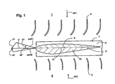
- FIG. 1 shows in schematic simplification an aerodynamically effective stage of a generic turbine as a plan view of a portion of the impeller 1.
- This includes a hub 2 with a plurality of turbine blades 3, wherein one is shown in profile in the figure.
- the components of the distributor are arranged on both sides of the impeller 1, the components of the distributor are arranged.
- Sketched is a first vane assembly 4, which is located upstream of the impeller 1 in an inflow from the first flow channel section 7. In an opposite flow direction, an inflow from the second flow channel portion 8, the second vane assembly 5 is upstream.
- first vane arrangement 4 deflects the flow more strongly than the second vane arrangement 5.
- first vane arrangement 4 is adapted for the first channel-side flow velocity vk1, which in the illustrated case is greater than the second one and / or the maximum value Channel-side flow velocity vk2 from the opposite direction. For these, the first vane assembly 4 is designed.
- FIG. 1 Another out FIG. 1 apparent asymmetry relates to the profile of the turbine blade 3 shown, which differs at least for the present section of the usual, the profile chord 17 symmetrical design.
- the bi-directional approachability must be maintained for the asymmetrically selected profile according to the invention, so that the profile consists of a first profile half 9 and a second profile half 10 which have matching profile depths, connect continuously to one another and which themselves are derived from symmetrical profiles adapted to the flow characteristic ,
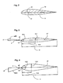
- FIG. 2 shows the first profile half 9 and the second profile half 10 with different hatchings, so that the assembly opposite to the chord 17 is illustrated. This results in a curved profile - this is clear from the course of the dashed skeleton line 18, wherein each of the two profile halves 9, 10, a separate thickness profile can be assigned.
- FIG. 3 shows the derivative of the first profile half 9. It is assumed for a given rated speed belonging to the respective flow direction, the first effective flow velocity veff1, which is composed of the first maximum fluid velocity v1 and the negative rotational velocity u vectorial. This results in a flow angle a1.
- an adapted profile which is symmetrical to the profile chord 17, is selected which is defined for a specific profile depth 11 by a thickness distribution. Characteristic of the selected thickness distribution are thickness 12.1, 12.2, thickness backing 13.1, 13.2 and profile nose radius 14.1, 14.2 for rounding the profile at the leading edge 15th
- the starting point is a moderate, first maximum fluid velocity v1.
- the resulting profile is elongated and has a small thickness 12.1, a large thickness reserve 13.1 and a small profile nose radius 14.1.
- Such an elongated one A stretched profile generates a low friction, but allows only small flow angles a1 to the occurrence of a large-scale stall.
- the first profile half 9, which is made of the in FIG. 3 is derived profile is on the suction side for the relevant direction of flow on the overall profile in FIG. 2 stated.
- FIG. 4 shows the derivative of the second profile half 10, for the in FIG. 4 shown inflow direction is suction side. It is assumed that a second maximum fluid velocity v2 from this direction, which is significantly greater than the first maximum fluid velocity v1 FIG. 3 is.
- a second effective flow velocity veff2 results, which is greater in magnitude than veff1 and leads to a larger flow angle a2.
- FIG. 4 sketched profile adapted and pointing at one opposite FIG. 3 constant profile depth 11 a greater thickness 12.2, a smaller thickness reserve 13.2 and a larger profile nose radius 14.2.
- a profile geometry adapted in this way. Consequently, from this profile, the second profile half 10 is derived, which then for the in FIG. 4 present inflow direction is present on the suction side of the overall profile - this is in FIG. 2 shown.
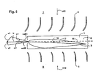
- FIG. 5 shows a further embodiment variant of the invention with a caused by an inclination of the turbine blades 3 on the hub 2 of the impeller 1 additional asymmetry.
- This measure is combined with an asymmetrically designed distributor and a profile for the chord 17 asymmetric profile for the turbine blade 3.
- the angle of attack 19 between the chord 17 and the rotation plane 16, which is preferably selected smaller than 5 ° the flow angle a1 at the same time Increase in the Angle of flow a2 additionally reduced.
- vk1 which is greater than the second channel-side flow velocity vk2.
- FIG. 6 shows a sketch of a turbine according to the invention with two aerodynamically effective stages.
- Sketched is a first impeller 1.1 with a first hub 2.1, which carries a plurality of turbine blades, with only a first turbine blade 3.1 is shown in profile section.
- a second impeller 1.2 is shown with a second hub 2.2 and a second turbine blade 3.2.
- the two wheels 1.1 and 1.2 are rigidly interconnected and serve to drive an electric generator (not shown).
- a two-stage or multi-stage constructed generic turbine is therefore advantageous because the maximum pressure reduction for safe prevention of transonic flow in the wake is limited; two or more stages therefore serve to increase efficiency.
- a direction-dependent flow characteristic it should be noted with two or more stages that an additional swirl component is present in the flow after each of the wheels due to the rotor effect. It is therefore preferred between the first impeller 1.1 and the second impeller 1.2 an additional, middle vane assembly 6 is used, which serves to return the swirl.
- the influence of the impeller 1.1 after passing through the middle vane arrangement 6 is compensated.
- the first aerodynamically effective stage 21, the first impeller 1.1 and the first vane assembly 4th and the second vane assembly 5 calculated.
- the second aerodynamically effective stage 22 includes the second impeller 2.2, the first vane assembly 4, and the second vane assembly 5, respectively.
- the first vane assembly 4 is formed asymmetrically to the second vane assembly 5, that is, it generates a different degree of deflection for a matching flow.
- a turbine blade 3 which is articulated rotatably on the hub 2
- the break-off characteristic is further improved by allowing a passive pitch setting, in particular for critical, high flow coefficients, a certain angle of incidence of the turbine blade to the plane of rotation and thus a reduced flow angle.
- stops for rotational movements may be provided, which are arranged asymmetrically to the plane of rotation, so that in one direction, a further swinging of the turbine blade is possible.
- the inventive measures can be combined with a flexible or partially flexible turbine blade.
Landscapes
- Engineering & Computer Science (AREA)
- Mechanical Engineering (AREA)
- General Engineering & Computer Science (AREA)
- Chemical & Material Sciences (AREA)
- Combustion & Propulsion (AREA)
- Physics & Mathematics (AREA)
- Fluid Mechanics (AREA)
- Turbine Rotor Nozzle Sealing (AREA)
Description
Die Erfindung betrifft eine bidirektionale Turbine, die beim Wechsel der Anströmungsrichtung ihren Drehsinn beibehält, bevorzugt eine Wells-Turbine, und eine Energieerzeugungsanlage, insbesondere ein Wellenkraftwerk, das eine solche Turbine umfasst.The invention relates to a bidirectional turbine, which retains its direction of rotation when changing the direction of flow, preferably a Wells turbine, and a power generation plant, in particular a wave power plant comprising such a turbine.
Bidirektional anströmbare Turbinen mit gleichsinnigem Umlauf werden beispielsweise zur Energiegewinnung mittels Wellenkraft eingesetzt. Dabei wird die Wellenenergie meist indirekt zum Antrieb der Turbine verwendet, indem eine Meereswelle durch einen unterirdischen Zugang in eine Wellenkammer eintritt und mit dem sich hebenden und fallenden Wasserspiegel in der Wellenkammer ein darüber befindliches Luftvolumen mit oszillierenden Druckschwankungen beaufschlagt. Wird zum Luftvolumen in der Wellenkammer ein zum Außenbereich führender Strömungskanal angelegt, in dem sich eine Luftturbine befindet, kann durch die im Strömungskanal resultierende Luftströmung eine gattungsgemäße Luftturbine betrieben werden.Bidirectionally flowable turbines with the same direction are used, for example, for energy production by wave force. The wave energy is usually used indirectly to drive the turbine by entering a sea wave through an underground access in a wave chamber and applied to the rising and falling water level in the wave chamber befindliches air volume with oscillating pressure fluctuations. If, for the volume of air in the wave chamber, a flow channel leading to the outside area is created, in which an air turbine is located, a generic air turbine can be operated by the air flow resulting in the flow channel.
Eine typische Bauform einer bidirektional anströmbaren Turbine mit gleichsinnigem Umlauf stellt eine Wells-Turbine dar. Diese kann als Axial- oder Radialturbine ausgebildet sein und umfasst ein oder mehrere Laufräder, die vorzugsweise eine Nabe mit darauf befestigten Turbinenblättern aufweisen. Die einzelnen Turbinenblätter sind zur Realisierung einer beidseitigen Anströmbarkeit bezüglich der Profilsehne symmetrisch angelegt und weisen einen tropfenförmigen Profilverlauf auf. Die Profilsehne liegt für Axialturbinen typischerweise in der Rotationsebene des Laufrads. Hierzu wird beispielhaft auf die
Ferner sind aus der
Weitere Ausgestaltungen für Wells-Turbinen sind der
Der Erfindung liegt die Aufgabe zugrunde, eine bidirektional anströmbare, gleichsinnig umlaufende Turbine, insbesondere eine Wells-Turbine, so zu gestalten, dass ihr gemittelter Wirkungsgrad gesteigert und die Ausbildung von Instabilitäten, die insbesondere aus Strömungsabrissen resultieren, verringert werden. Entsprechend soll die Turbine eine Gestaltung aufweisen, die einen geräuschverminderten Betrieb erlaubt.The object of the invention is to design a bidirectionally flowable, co-rotating turbine, in particular a Wells turbine, in such a way that its averaged efficiency is increased and the formation of instabilities, resulting in particular from stalling, is reduced. Accordingly, the turbine should have a design that allows a noise-reduced operation.
Die der Erfindung zugrunde liegende Aufgabe wird durch die Merkmale des unabhängigen Anspruchs gelöst. Dabei gehen die Erfinder von der Erkenntnis aus, dass in einem mit einer Wellenkammer verbundenen Strömungskanal eine oszillierende Luftströmung vorliegt, die nicht sinusförmig ist. Einer der Gründe dafür sind Asymmetrien der Gesamtanlage. So liegen unterschiedliche Randbedingungen an den Mündungen des Strömungskanals vor, da eine Öffnung zur Wellenkammer und die andere in den Freibereich mit Umgebungsdruck führt. Ferner resultiert durch zusätzliche Komponenten im Strömungskanal, wie der Drosselklappe, dem Sicherheitsventil, dem Schalldämpfer und jeweils einseitig vorgesehenen oder zu beiden Seiten unterschiedlich gestalteten Diffusoren oder Konfusoren eine Abweichung vom sinusförmigen Strömungsverlauf im Strömungskanal.The object underlying the invention is solved by the features of the independent claim. The inventors start from the knowledge that in an associated with a wave chamber flow channel an oscillating air flow is present, which is not sinusoidal. One of the reasons for this are asymmetries of the overall system. Thus, there are different boundary conditions at the mouths of the flow channel, as an opening leads to the shaft chamber and the other in the open area with ambient pressure. Further, resulting from additional components in the flow channel, such as the throttle valve, the safety valve, the muffler and provided on one side or on both sides differently shaped diffusers or Confusors a deviation from the sinusoidal flow in the flow channel.
Des Weiteren führt die Wellencharakteristik selbst zu einer wesentlichen Richtungsabhängigkeit der Durchströmung des Strömungskanals. Durch ein Anstellen der Welle beim Erreichen des Flachwasserbereichs weicht die Wellenform zunehmend vom periodischen Verlauf ab - dabei stellt sich der Wellenberg steil auf. Als Resultat entsteht mit steigendem Wasserspiegel in der Wellenkammer ein kurzer und starker Druckpuls, der zu einem entsprechenden Durchfluss im Strömungskanal führt. Hiervon weicht die Charakteristik beim Auslaufen der Welle und Absinken des Wasserspiegels in der Wellenkammer ab, wobei ein schwächerer, aber gleichmäßigerer Durchfluss erzeugt wird.Furthermore, the wave characteristic itself leads to a significant directional dependence of the flow through the flow channel. By adjusting the wave when reaching the shallow water area, the waveform deviates increasingly from the periodic course - while the wave crest rises steeply. As a result, with a rising water level in the wave chamber, a short and strong pressure pulse is created which leads to a corresponding flow in the flow channel. This deviates from the characteristics of the wave coasting and the sinking of the water level in the wave chamber, producing a weaker but more uniform flow.
Für die erfindungsgemäße Turbine wird eine Anpassung an die richtungsabhängige Anströmung vorgenommen. Hierdurch entsteht eine asymmetrische Gestaltung wenigstens einer aerodynamisch aktiven Stufe, wobei unter einer aerodynamisch aktiven Stufe ein Laufrad oder, falls vorhanden, zusätzlich der dem Laufrad zugeordnete Leitapparat verstanden wird. Die erfindungsgemäß vorgesehene Asymmetrie bezieht sich dabei auf die aerodynamische Stufe als Ganzes, so dass für eine erste Durchflussrichtung eine von der entgegengesetzten, zweiten Durchflussrichtung abweichende Charakteristik vorliegt. Ferner wird das Profil der Turbinenblätter eines Laufrads so gestaltet, dass das Erfordernis der bidirektionalen Anströmbarkeit hinreichend gut durch jedes einzelne Turbinenblatt erfüllt wird und zugleich die geforderte Asymmetrie zur Anpassung der mit der Anströmungsrichtung veränderten Anströmungscharakteristik realisiert werden kann. Dabei wird das Profil entlang der Profilsehne in zwei Profilhälften aufgeteilt. Demnach liegen eine ersten Profilhälfte und eine zweite Profilhälfte mit übereinstimmender Profiltiefe vor, die an den Profilnasen stetig ineinander übergehen und die gegenüberliegend zur Profilsehne angeordnet sind.For the turbine according to the invention an adaptation to the direction-dependent flow is made. This results in an asymmetrical design of at least one aerodynamically active stage, wherein under an aerodynamically active stage, an impeller or, if present, additionally associated with the impeller diffuser is understood. The asymmetry provided according to the invention relates in this case to the aerodynamic stage as a whole, so that there is a characteristic deviating from the opposite, second flow direction for a first flow direction. Furthermore, the profile of the turbine blades of an impeller is designed so that the requirement of bidirectional Anströmbarkeit is sufficiently well met by each turbine blade and at the same time the required asymmetry for adjusting the flow direction changed with the flow characteristic can be realized. The profile is divided along the chord in two profile halves. Accordingly, there are a first profile half and a second profile half with matching tread depth, which merge into one another continuously at the profile noses and which are arranged opposite to the chord.
Sowohl die erste Profilhälfte als auch die zweite Profilhälfte ist ein Halbprofil, jeweils entnommen aus einem symmetrisch zur Profilsehne gestalteten Profil, das an die zur jeweiligen Anströmungsrichtung gehörende Strömungscharakteristik angepasst ist. Die einer bestimmten Anströmungsrichtung zugeordnete Profilhälfte liegt auf der Saugseite des erfindungsgemäßen Gesamtprofils, auf der es ihre wesentliche aerodynamische Wirkung entfaltet. Ein Kriterium zur Anpassung der saugseitigen Profilhälfte ist der maximal für die jeweilige Strömungsrichtung auftretende Durchflusskoeffizient. Hierbei wird die entsprechende Profilhälfte so gestaltet, dass ein saugseitig auftretender, vollflächiger Strömungsabriss möglichst sicher ausgeschlossen wird. Dabei kommt zur Profilanpassung insbesondere die saugseitige Dickenverteilung in Frage, so dass die Dicke, die Dickenrücklage sowie der Profilnasenradius an die Strömungscharakteristik für die jeweilige Anströmungsrichtung angepasst werden.Both the first profile half and the second profile half is a half profile, each taken from a symmetrically shaped profile chord profile, which is adapted to the flow characteristic associated with the respective inflow direction. The profile half assigned to a specific inflow direction lies on the suction side of the overall profile according to the invention, on which it develops its essential aerodynamic effect. One criterion for adapting the suction-side profile half is the maximum flow coefficient occurring for the respective flow direction. Here, the corresponding profile half is designed so that a suction occurring, full-surface stall is excluded as safe as possible. In particular, the intake-side thickness distribution is suitable for profile adaptation, so that the thickness, the thickness reserve and the profile nose radius are adapted to the flow characteristic for the respective flow direction.
Für Wellenkraftwerke, die nach dem OWC-Prinzip arbeiten (Oscillating Wave Column), wird bevorzugt das erfindungsgemäße Profil der Turbinenblätter so gestaltet, dass die bei einer Ausströmung, das heißt einer Strömung von der Wellenkammer in Richtung des Außenbereichs, saugseitig liegende Profilhälfte das dickere Profil mit einer geringeren Dickenrücklage aufweist. Ferner werden hierfür größere Profilnasenradien bevorzugt. Hierbei macht man sich den Umstand zunutze, dass dicke Profile und große Profilnasenradien bei den für die vorliegende Anwendung typischerweise hinreichend großen Reynolds-Zahlen ein verbessertes Abreißverhalten zeigen. Auf der gegenüberliegenden Seite und damit für die andere Profilhälfte, die beim Einsaugzyklus saugseitige, treten mit geringerer Wahrscheinlichkeit die genannten Instabilitäten auf. Entsprechend können schlankere Profile mit größerer Dickenrücklage, die zu einem geringeren Widerstand führen, verwendet werden. Insgesamt entsteht ein Profil, das ein verbessertes Ablösungsverhalten zeigt. Des Weiteren ist der von der Turbine abgestrahlte Schallpegel reduziert.For wave power plants that operate on the OWC principle (Oscillating Wave Column), the profile of the turbine blades according to the invention is preferably designed so that in a outflow, that is, a flow from the shaft chamber in the direction of the outside, the suction side lying profile half the thicker profile having a lower thickness reserve. Furthermore, larger profile nose radii are preferred for this purpose. This makes use of the fact that thick profiles and large profile nose radii show an improved tear-off behavior at the typically sufficiently high Reynolds numbers for the present application. On the opposite side, and thus for the other half of the profile, the suction side at the suction cycle, the likelihood of the instabilities mentioned is less likely. Accordingly, slimmer profiles with larger thickness backing, resulting in less resistance, can be used. Overall, a profile is created which shows an improved detachment behavior. Furthermore, the sound level emitted by the turbine is reduced.
Für eine Weitergestaltung der Erfindung wird der Leitapparat einer aerodynamisch wirksamen Stufe asymmetrisch gestaltet. Hierbei ist entweder nur eine auf einer Seite des Laufrads der Stufe angeordnete Leitschaufelanordnung vorhanden oder bei einer beidseitigen Leitschaufelanordnung bestehen geometrisch bedingte Unterschiede im Ablenkungsgrad für eine übereinstimmende Anströmung. Bevorzugt wird der Leitapparat so angepasst, dass die stromaufwärtig zum Laufrad positionierte Leitschaufelanordnung für den maximal aus dieser Strömungsrichtung auftretenden Durchfluss geeignet ist. Für eine hohe Anströmungsgeschwindigkeit aus einer Richtung werden entsprechend hohe Ablenkungswinkel durch die Leitschaufelanordnung bewirkt, so dass der Anströmungswinkel an den Turbinenblättern des Laufrads für diese Anströmungsrichtung reduziert ist und zugleich die effektive Anströmungsgeschwindigkeit verringert wird.For a further embodiment of the invention, the nozzle of an aerodynamically effective stage is designed asymmetrically. This is either only one on one Side of the impeller of the stage arranged vane arrangement available or exist in a two-sided vane arrangement geometrically induced differences in the degree of deflection for a matching flow. Preferably, the distributor is adapted so that the upstream of the impeller positioned vane assembly is suitable for the maximum occurring from this flow direction flow. For a high flow velocity from one direction correspondingly high deflection angles are caused by the vane arrangement, so that the inflow angle is reduced at the turbine blades of the impeller for this direction of flow and at the same time the effective flow rate is reduced.
Eine dritte Ausgestaltungsvariante der Erfindung betrifft zusätzlich zum asymmetrischen Profil einen nicht verschwindenden Anstellwinkel der Profilsehne des Turbinenblatts relativ zur Rotationsebene des Laufrads der jeweiligen Stufe. Dabei wird eine Ausgestaltung mit einer starren Fixierung der Turbinenblätter an der Nabe des Laufrads aufgrund konstruktiver Einfachheit bevorzugt. Demnach ist der gewählte Anstellwinkel fix und dient dazu, den Anströmungswinkel für die Anströmungsrichtung mit höheren Geschwindigkeitsspitzen zu reduzieren und den Anströmungswinkel für die Gegenrichtung mit geringeren maximalen Strömungsgeschwindigkeiten entsprechend zu erhöhen.A third embodiment variant of the invention relates in addition to the asymmetrical profile a non-vanishing angle of attack of the chord of the turbine blade relative to the plane of rotation of the impeller of the respective stage. In this case, an embodiment with a rigid fixation of the turbine blades on the hub of the impeller due to constructive simplicity is preferred. Accordingly, the selected angle of attack is fixed and serves to reduce the inflow angle for the direction of flow at higher speed peaks and to correspondingly increase the inflow angle for the opposite direction with lower maximum flow rates.
Nachfolgend wird die Erfindung anhand von Ausgestaltungsbeispielen und in Verbindung mit Figurendarstellungen genauer erläutert. In diesen ist im Einzelnen Folgendes dargestellt:
- Figur 1
- zeigt eine erfindungsgemäß gestaltete aerodynamisch wirksame Stufe für eine bidirektional anströmbare Turbine mit gleichsinnigem Umlauf.
Figur 2- zeigt ein asymmetrisch gestaltetes Profil mit zwei gegenüberliegend zur Profilsehne angeordneten Profilhälften.
Figuren 3 und 4- zeigen die Ableitung der beiden Profilhälften von
Figur 2 Figur 5- zeigt eine erfindungsgemäß gestaltete aerodynamisch wirksame Stufe mit einem asymmetrischen Leitapparat und einem Anstellwinkel für die Profilsehne eines Turbinenblatts relativ zur Rotationsebene für ein asymmetrisch gestaltetes Profil.
Figur 6- zeigt eine erfindungsgemäße Turbine mit zwei aerodynamisch wirksamen Stufen.
- FIG. 1
- shows an inventively designed aerodynamically effective stage for a bi-directionally flowable turbine with the same direction of circulation.
- FIG. 2
- shows an asymmetrically shaped profile with two opposite to the chord profile arranged profile halves.
- FIGS. 3 and 4
- show the derivative of the two profile halves of
FIG. 2 from the profile chord symmetrical profiles. - FIG. 5
- shows an inventively designed aerodynamically effective stage with an asymmetric nozzle and an angle of attack for the chord of a turbine blade relative to the plane of rotation for an asymmetrically shaped profile.
- FIG. 6
- shows a turbine according to the invention with two aerodynamically effective stages.
Die in
Eine weitere aus
Für den in
Entsprechend ergibt sich unter Annahme der gleichen negativen Umlaufgeschwindigkeit u aus der vektoriellen Geschwindigkeitsaddition von u und v2 eine zweite effektive Anströmungsgeschwindigkeit veff2, die betragsmäßig größer als veff1 ist und zu einem größeren Anströmungswinkel a2 führt.Accordingly, assuming the same negative rotational speed u from the vectorial velocity addition of u and v2, a second effective flow velocity veff2 results, which is greater in magnitude than veff1 and leads to a larger flow angle a2.
Hierauf aufbauend ist das in
Eine zwei- oder mehrstufig aufgebaute gattungsgemäße Turbine ist deshalb von Vorteil, da der maximale Druckabbau zum sicheren Verhindern einer transsonischen Strömung im Nachlauf begrenzt ist; zwei oder mehr Stufen dienen daher der Wirkungsgradsteigerung. Im Hinblick auf eine richtungsabhängige Strömungscharakteristik ist bei zwei oder mehr Stufen zu beachten, dass durch die Rotorwirkung nach jedem der Laufräder eine zusätzliche Drallkomponente in der Strömung vorliegt. Es wird daher bevorzugt zwischen dem ersten Laufrad 1.1 und dem zweiten Laufrad 1.2 eine zusätzliche, mittlere Leitschaufelanordnung 6 verwendet, die der Rückführung des Dralls dient.A two-stage or multi-stage constructed generic turbine is therefore advantageous because the maximum pressure reduction for safe prevention of transonic flow in the wake is limited; two or more stages therefore serve to increase efficiency. With regard to a direction-dependent flow characteristic, it should be noted with two or more stages that an additional swirl component is present in the flow after each of the wheels due to the rotor effect. It is therefore preferred between the first impeller 1.1 and the second impeller 1.2 an additional,
Demnach gleicht sich für einen Zustrom aus dem ersten Strömungskanalabschnitt 7 der Einfluss des Laufrads 1.1 nach dem Durchlaufen der mittleren Leitschaufelanordnung 6 aus. Entsprechendes gilt für einen Zustrom aus dem zweiten Strömungskanalabschnitt 8, der idealisiert betrachtet nach dem Passieren des zweiten Laufrads 1.2 und dem Durchströmen der mittleren Leitschaufelanordnung 6 im Wesentlichen der Anströmungssituation entspricht, die für die genannte Zuströmungsrichtung nach dem Durchströmen der zweiten Leitschaufelanordnung 5 vorliegt. Demnach wird zur ersten aerodynamisch wirksamen Stufe 21 das erste Laufrad 1.1 und die erste Leitschaufelanordnung 4 sowie die zweite Leitschaufelanordnung 5 gerechnet. Die zweite aerodynamisch wirksame Stufe 22 umfasst entsprechend das zweite Laufrad 2.2, die erste Leitschaufelanordnung 4 und die zweite Leitschaufelanordnung 5.Accordingly, for an inflow from the first
Erfindungsgemäß ist die erste Leitschaufelanordnung 4 asymmetrisch zur zweiten Leitschaufelanordnung 5 ausgebildet, das heißt sie erzeugt einen unterschiedlichen Ablenkungsgrad für eine übereinstimmende Anströmung. Eine zusätzliche Asymmetrie liegt für die Profile der Turbinenblätter 3.1, 3.2 vor, die beide entsprechend zu
Weitere Ausgestaltungen der Erfindung sind denkbar. Dabei kann insbesondere ein drehbar an der Nabe 2 angelenktes Turbinenblatt 3 mit dem erfindungsgemäß asymmetrischen Profil verwendet werden. Hierdurch wird die Abreißcharakteristik nochmals verbessert, indem eine passive Pitch-Einstellung, insbesondere für kritische, hohe Durchflusskoeffizienten, einen gewissen Anstellwinkel des Turbinenblatts zur Rotationsebene und damit einen verringerten Anströmungswinkel zulässt. Dabei können Anschläge für Drehbewegungen vorgesehen sein, die asymmetrisch zur Rotationsebene angeordnet sind, so dass in eine Richtung ein weiteres Aufschwingen des Turbinenblatts möglich ist. Zusätzlich können die erfindungsgemäßen Maßnahmen mit einem flexiblen oder teilflexiblen Turbinenblatt kombiniert werden. Darüber hinaus ist es denkbar, eine erfindungsgemäße Turbine mit gasförmigem oder flüssigem Fluid anzutreiben.Further embodiments of the invention are conceivable. In this case, in particular, a
Claims (10)
- A turbine for circulating in the same direction under bidirectional inflow, comprising1.1 at least one aerodynamic active stage having an impeller (1) comprising at least one turbine blade (3), characterized in that1.2 the aerodynamic active stage is asymmetrical as a whole relative to the inflow direction, in that the profile of at least one partial segment of the turbine blade (3) is composed of a first profile half (9) and a second profile half (9) having matching profile depths, disposed opposite the profile chord (17), and comprising a continuous transition at the inflow edge (15), wherein the first profile half (9) and the second profile half (10) comprise profile curves that differ from each other.
- The turbine according to claim 1, characterised in that the first profile half (9) and the second profile half (10) have a different thickness distribution.
- The turbine according to claim 2, characterised in that the first profile half (9) and the second profile half (10) have different thicknesses (12.1, 12.2).
- The turbine according to claim 2 or 3, characterised in that the first profile half (9) and the second profile half (10) have a different thickness reserves (13.1, 13.2).
- The turbine according to any one of claims 2 to 4, characterised in that the first profile half (9) and the second profile half (10) have different profile nose radii (14.1, 14.2) at the inflow edge (15).
- The turbine according to any one of claims 1 to 5 comprising 6.1 a first guide vane arrangement (5) and a second guide arrangement (6), wherein the impeller (1) is placed between the first guide vane arrangement (5) and the second guide vane arrangement (6) and wherein the first guide vane arrangement (5) is configured asymmetrically to the second guide vane arrangement (6).
- The turbine according to claim 6, characterised in that the first guide vane arrangement (5) under the same inflow conditions produces a deflection of the flow different from the second guide vane arrangement (6).
- The turbine according to any one of the preceding claims, wherein the impeller (1) comprises a plurality of turbine blades (3), characterised in that the turbine blades (3) are fixed to the impeller (1) with an angle of attack (19).
- Energy production plant comprising9.1 a turbine according to any one of claims 1 to 8 for which the first maximum fluid velocity (v1) in a first flow direction differs from the second maximum fluid velocity (v2) in the opposite second flow direction and the deviation of the first profile half (9) from the second profile half (9) is matched to the difference between the maximum fluid velocities (v1, v2).
- Energy production plant according to claim 9, characterised in that the energy production plant serves to use wave energy.
Applications Claiming Priority (2)
| Application Number | Priority Date | Filing Date | Title |
|---|---|---|---|
| DE102009018924A DE102009018924A1 (en) | 2009-04-28 | 2009-04-28 | Bidirectional flowable turbine |
| PCT/EP2010/001439 WO2010124762A2 (en) | 2009-04-28 | 2010-03-09 | Bidirectionally impingeable turbine |
Publications (2)
| Publication Number | Publication Date |
|---|---|
| EP2425120A2 EP2425120A2 (en) | 2012-03-07 |
| EP2425120B1 true EP2425120B1 (en) | 2013-05-08 |
Family
ID=42813628
Family Applications (1)
| Application Number | Title | Priority Date | Filing Date |
|---|---|---|---|
| EP10708133.3A Not-in-force EP2425120B1 (en) | 2009-04-28 | 2010-03-09 | Bidirectionally impingeable turbine |
Country Status (5)
| Country | Link |
|---|---|
| EP (1) | EP2425120B1 (en) |
| DE (1) | DE102009018924A1 (en) |
| ES (1) | ES2410375T3 (en) |
| PT (1) | PT2425120E (en) |
| WO (1) | WO2010124762A2 (en) |
Cited By (1)
| Publication number | Priority date | Publication date | Assignee | Title |
|---|---|---|---|---|
| US12078145B2 (en) | 2014-08-05 | 2024-09-03 | Biomerenewables Inc. | Fluidic turbine structure |
Families Citing this family (3)
| Publication number | Priority date | Publication date | Assignee | Title |
|---|---|---|---|---|
| EP3608505B1 (en) * | 2018-08-08 | 2021-06-23 | General Electric Company | Turbine incorporating endwall fences |
| IT202100002240A1 (en) | 2021-02-02 | 2022-08-02 | Gen Electric | TURBINE ENGINE WITH REDUCED TRANSVERSE FLOW VANES |
| WO2022175870A1 (en) * | 2021-02-22 | 2022-08-25 | Howden Axial Fans Aps | Guide vanes for fully reversible turbomachinery |
Family Cites Families (7)
| Publication number | Priority date | Publication date | Assignee | Title |
|---|---|---|---|---|
| US3912938A (en) * | 1974-01-25 | 1975-10-14 | Gregory D Filipenco | Electrical stations operated by waves |
| GB1574379A (en) | 1977-08-24 | 1980-09-03 | English Electric Co Ltd | Turbines and like rotary machines |
| CH659851A5 (en) | 1981-06-05 | 1987-02-27 | Escher Wyss Ag | TURBINE. |
| JPS63219801A (en) | 1987-03-06 | 1988-09-13 | Saga Univ | Turbine for wave activated power generation with self-adjustable pitch blade |
| GB9022713D0 (en) | 1990-10-18 | 1990-11-28 | Wells Alan A | Wave power apparatus |
| AUPO361396A0 (en) * | 1996-11-14 | 1996-12-12 | Energetech Australia Pty Limited | Parabolic wave focuser & double ended aerofoil turbine |
| US20070231148A1 (en) * | 2006-04-03 | 2007-10-04 | Lehoczky Kalman N | Reversing free flow propeller turbine |
-
2009
- 2009-04-28 DE DE102009018924A patent/DE102009018924A1/en not_active Withdrawn
-
2010
- 2010-03-09 EP EP10708133.3A patent/EP2425120B1/en not_active Not-in-force
- 2010-03-09 WO PCT/EP2010/001439 patent/WO2010124762A2/en active Application Filing
- 2010-03-09 ES ES10708133T patent/ES2410375T3/en active Active
- 2010-03-09 PT PT107081333T patent/PT2425120E/en unknown
Cited By (1)
| Publication number | Priority date | Publication date | Assignee | Title |
|---|---|---|---|---|
| US12078145B2 (en) | 2014-08-05 | 2024-09-03 | Biomerenewables Inc. | Fluidic turbine structure |
Also Published As
| Publication number | Publication date |
|---|---|
| WO2010124762A2 (en) | 2010-11-04 |
| PT2425120E (en) | 2013-06-04 |
| WO2010124762A3 (en) | 2010-12-23 |
| ES2410375T3 (en) | 2013-07-01 |
| EP2425120A2 (en) | 2012-03-07 |
| DE102009018924A1 (en) | 2010-11-04 |
Similar Documents
| Publication | Publication Date | Title |
|---|---|---|
| EP2623793B1 (en) | Flow machine with blade row | |
| EP1671030B1 (en) | Rotor blade for a wind power converter | |
| DE102006057063B3 (en) | Stator stage of an axial compressor of a turbomachine with cross blades to increase efficiency | |
| DE102012206105A1 (en) | IMPELLER AND FLOW MACHINE WITH THE IMPELLER | |
| DE102009025857A1 (en) | Wind turbine rotor blade floor plans with twisted and tapered tips | |
| EP2146053A1 (en) | Axial turbomachine with low tip leakage losses | |
| EP2425120B1 (en) | Bidirectionally impingeable turbine | |
| EP3066337B1 (en) | Rotor blade of a wind turbine and a wind turbine | |
| EP3147499B1 (en) | Rotor blade comprising a sound optimized profile and method for manufacturing a rotor blade | |
| EP4083433A1 (en) | Fan and fan blade | |
| EP1244872A1 (en) | Rotor blade for a wind power installation | |
| DE4310104C2 (en) | Process for reducing noise emissions and for improving air performance and efficiency in an axial turbomachine and turbomachine | |
| EP2978967B1 (en) | Rotor blade of a wind turbine having a winglet | |
| EP2232058B1 (en) | Air turbine for a wave power station | |
| DE102009057449B3 (en) | Turbine blade for a bidirectionally inflatable water turbine | |
| DE3148995A1 (en) | Axial turbine | |
| CH714302A2 (en) | Aerodynamically optimized rotor blade. | |
| WO2013190117A1 (en) | Rotor for a vertical-axis wind turbine | |
| WO2010000229A2 (en) | Blade cascade for a flow engine and flow engine comprising said blade cascade | |
| WO2021004853A1 (en) | Rotor blade for a wind turbine and wind turbine | |
| EP2636892A2 (en) | Wind power plant and method for generating of rotary energy from wind | |
| EP3686423B1 (en) | Rotor blade for a wind turbine | |
| DE102008051297B3 (en) | Rotor blade of a wind turbine | |
| WO2012020041A1 (en) | Device for converting the energy of a flowing medium | |
| DE102014212729A1 (en) | Hydropower plant with bi-directional operation |
Legal Events
| Date | Code | Title | Description |
|---|---|---|---|
| PUAI | Public reference made under article 153(3) epc to a published international application that has entered the european phase |
Free format text: ORIGINAL CODE: 0009012 |
|
| 17P | Request for examination filed |
Effective date: 20110209 |
|
| AK | Designated contracting states |
Kind code of ref document: A2 Designated state(s): AT BE BG CH CY CZ DE DK EE ES FI FR GB GR HR HU IE IS IT LI LT LU LV MC MK MT NL NO PL PT RO SE SI SK SM TR |
|
| RIN1 | Information on inventor provided before grant (corrected) |
Inventor name: WEILEPP, JOCHEN Inventor name: ARLITT, RAPHAEL |
|
| DAX | Request for extension of the european patent (deleted) | ||
| GRAP | Despatch of communication of intention to grant a patent |
Free format text: ORIGINAL CODE: EPIDOSNIGR1 |
|
| GRAS | Grant fee paid |
Free format text: ORIGINAL CODE: EPIDOSNIGR3 |
|
| GRAA | (expected) grant |
Free format text: ORIGINAL CODE: 0009210 |
|
| AK | Designated contracting states |
Kind code of ref document: B1 Designated state(s): AT BE BG CH CY CZ DE DK EE ES FI FR GB GR HR HU IE IS IT LI LT LU LV MC MK MT NL NO PL PT RO SE SI SK SM TR |
|
| REG | Reference to a national code |
Ref country code: GB Ref legal event code: FG4D Free format text: NOT ENGLISH |
|
| REG | Reference to a national code |
Ref country code: CH Ref legal event code: EP Ref country code: AT Ref legal event code: REF Ref document number: 611231 Country of ref document: AT Kind code of ref document: T Effective date: 20130515 |
|
| REG | Reference to a national code |
Ref country code: PT Ref legal event code: SC4A Free format text: AVAILABILITY OF NATIONAL TRANSLATION Effective date: 20130528 |
|
| REG | Reference to a national code |
Ref country code: IE Ref legal event code: FG4D Free format text: LANGUAGE OF EP DOCUMENT: GERMAN |
|
| REG | Reference to a national code |
Ref country code: ES Ref legal event code: FG2A Ref document number: 2410375 Country of ref document: ES Kind code of ref document: T3 Effective date: 20130701 |
|
| REG | Reference to a national code |
Ref country code: DE Ref legal event code: R096 Ref document number: 502010003271 Country of ref document: DE Effective date: 20130704 |
|
| REG | Reference to a national code |
Ref country code: LT Ref legal event code: MG4D |
|
| REG | Reference to a national code |
Ref country code: NL Ref legal event code: VDEP Effective date: 20130508 |
|
| PG25 | Lapsed in a contracting state [announced via postgrant information from national office to epo] |
Ref country code: NO Free format text: LAPSE BECAUSE OF FAILURE TO SUBMIT A TRANSLATION OF THE DESCRIPTION OR TO PAY THE FEE WITHIN THE PRESCRIBED TIME-LIMIT Effective date: 20130808 Ref country code: IS Free format text: LAPSE BECAUSE OF FAILURE TO SUBMIT A TRANSLATION OF THE DESCRIPTION OR TO PAY THE FEE WITHIN THE PRESCRIBED TIME-LIMIT Effective date: 20130908 Ref country code: GR Free format text: LAPSE BECAUSE OF FAILURE TO SUBMIT A TRANSLATION OF THE DESCRIPTION OR TO PAY THE FEE WITHIN THE PRESCRIBED TIME-LIMIT Effective date: 20130809 Ref country code: LT Free format text: LAPSE BECAUSE OF FAILURE TO SUBMIT A TRANSLATION OF THE DESCRIPTION OR TO PAY THE FEE WITHIN THE PRESCRIBED TIME-LIMIT Effective date: 20130508 Ref country code: FI Free format text: LAPSE BECAUSE OF FAILURE TO SUBMIT A TRANSLATION OF THE DESCRIPTION OR TO PAY THE FEE WITHIN THE PRESCRIBED TIME-LIMIT Effective date: 20130508 Ref country code: SI Free format text: LAPSE BECAUSE OF FAILURE TO SUBMIT A TRANSLATION OF THE DESCRIPTION OR TO PAY THE FEE WITHIN THE PRESCRIBED TIME-LIMIT Effective date: 20130508 Ref country code: SE Free format text: LAPSE BECAUSE OF FAILURE TO SUBMIT A TRANSLATION OF THE DESCRIPTION OR TO PAY THE FEE WITHIN THE PRESCRIBED TIME-LIMIT Effective date: 20130508 |
|
| PG25 | Lapsed in a contracting state [announced via postgrant information from national office to epo] |
Ref country code: PL Free format text: LAPSE BECAUSE OF FAILURE TO SUBMIT A TRANSLATION OF THE DESCRIPTION OR TO PAY THE FEE WITHIN THE PRESCRIBED TIME-LIMIT Effective date: 20130508 Ref country code: HR Free format text: LAPSE BECAUSE OF FAILURE TO SUBMIT A TRANSLATION OF THE DESCRIPTION OR TO PAY THE FEE WITHIN THE PRESCRIBED TIME-LIMIT Effective date: 20130508 Ref country code: CY Free format text: LAPSE BECAUSE OF FAILURE TO SUBMIT A TRANSLATION OF THE DESCRIPTION OR TO PAY THE FEE WITHIN THE PRESCRIBED TIME-LIMIT Effective date: 20130508 Ref country code: BG Free format text: LAPSE BECAUSE OF FAILURE TO SUBMIT A TRANSLATION OF THE DESCRIPTION OR TO PAY THE FEE WITHIN THE PRESCRIBED TIME-LIMIT Effective date: 20130808 |
|
| PG25 | Lapsed in a contracting state [announced via postgrant information from national office to epo] |
Ref country code: LV Free format text: LAPSE BECAUSE OF FAILURE TO SUBMIT A TRANSLATION OF THE DESCRIPTION OR TO PAY THE FEE WITHIN THE PRESCRIBED TIME-LIMIT Effective date: 20130508 |
|
| PG25 | Lapsed in a contracting state [announced via postgrant information from national office to epo] |
Ref country code: EE Free format text: LAPSE BECAUSE OF FAILURE TO SUBMIT A TRANSLATION OF THE DESCRIPTION OR TO PAY THE FEE WITHIN THE PRESCRIBED TIME-LIMIT Effective date: 20130508 Ref country code: CZ Free format text: LAPSE BECAUSE OF FAILURE TO SUBMIT A TRANSLATION OF THE DESCRIPTION OR TO PAY THE FEE WITHIN THE PRESCRIBED TIME-LIMIT Effective date: 20130508 Ref country code: DK Free format text: LAPSE BECAUSE OF FAILURE TO SUBMIT A TRANSLATION OF THE DESCRIPTION OR TO PAY THE FEE WITHIN THE PRESCRIBED TIME-LIMIT Effective date: 20130508 Ref country code: SK Free format text: LAPSE BECAUSE OF FAILURE TO SUBMIT A TRANSLATION OF THE DESCRIPTION OR TO PAY THE FEE WITHIN THE PRESCRIBED TIME-LIMIT Effective date: 20130508 |
|
| PG25 | Lapsed in a contracting state [announced via postgrant information from national office to epo] |
Ref country code: IT Free format text: LAPSE BECAUSE OF FAILURE TO SUBMIT A TRANSLATION OF THE DESCRIPTION OR TO PAY THE FEE WITHIN THE PRESCRIBED TIME-LIMIT Effective date: 20130508 Ref country code: RO Free format text: LAPSE BECAUSE OF FAILURE TO SUBMIT A TRANSLATION OF THE DESCRIPTION OR TO PAY THE FEE WITHIN THE PRESCRIBED TIME-LIMIT Effective date: 20130508 Ref country code: NL Free format text: LAPSE BECAUSE OF FAILURE TO SUBMIT A TRANSLATION OF THE DESCRIPTION OR TO PAY THE FEE WITHIN THE PRESCRIBED TIME-LIMIT Effective date: 20130508 |
|
| PLBE | No opposition filed within time limit |
Free format text: ORIGINAL CODE: 0009261 |
|
| STAA | Information on the status of an ep patent application or granted ep patent |
Free format text: STATUS: NO OPPOSITION FILED WITHIN TIME LIMIT |
|
| 26N | No opposition filed |
Effective date: 20140211 |
|
| REG | Reference to a national code |
Ref country code: DE Ref legal event code: R097 Ref document number: 502010003271 Country of ref document: DE Effective date: 20140211 |
|
| PG25 | Lapsed in a contracting state [announced via postgrant information from national office to epo] |
Ref country code: LU Free format text: LAPSE BECAUSE OF FAILURE TO SUBMIT A TRANSLATION OF THE DESCRIPTION OR TO PAY THE FEE WITHIN THE PRESCRIBED TIME-LIMIT Effective date: 20140309 |
|
| REG | Reference to a national code |
Ref country code: CH Ref legal event code: PL |
|
| PG25 | Lapsed in a contracting state [announced via postgrant information from national office to epo] |
Ref country code: CH Free format text: LAPSE BECAUSE OF NON-PAYMENT OF DUE FEES Effective date: 20140331 Ref country code: LI Free format text: LAPSE BECAUSE OF NON-PAYMENT OF DUE FEES Effective date: 20140331 |
|
| PG25 | Lapsed in a contracting state [announced via postgrant information from national office to epo] |
Ref country code: MT Free format text: LAPSE BECAUSE OF FAILURE TO SUBMIT A TRANSLATION OF THE DESCRIPTION OR TO PAY THE FEE WITHIN THE PRESCRIBED TIME-LIMIT Effective date: 20130508 |
|
| REG | Reference to a national code |
Ref country code: FR Ref legal event code: PLFP Year of fee payment: 7 |
|
| PG25 | Lapsed in a contracting state [announced via postgrant information from national office to epo] |
Ref country code: SM Free format text: LAPSE BECAUSE OF FAILURE TO SUBMIT A TRANSLATION OF THE DESCRIPTION OR TO PAY THE FEE WITHIN THE PRESCRIBED TIME-LIMIT Effective date: 20130508 |
|
| REG | Reference to a national code |
Ref country code: AT Ref legal event code: MM01 Ref document number: 611231 Country of ref document: AT Kind code of ref document: T Effective date: 20150309 |
|
| PG25 | Lapsed in a contracting state [announced via postgrant information from national office to epo] |
Ref country code: MC Free format text: LAPSE BECAUSE OF FAILURE TO SUBMIT A TRANSLATION OF THE DESCRIPTION OR TO PAY THE FEE WITHIN THE PRESCRIBED TIME-LIMIT Effective date: 20130508 |
|
| PG25 | Lapsed in a contracting state [announced via postgrant information from national office to epo] |
Ref country code: HU Free format text: LAPSE BECAUSE OF FAILURE TO SUBMIT A TRANSLATION OF THE DESCRIPTION OR TO PAY THE FEE WITHIN THE PRESCRIBED TIME-LIMIT; INVALID AB INITIO Effective date: 20100309 Ref country code: TR Free format text: LAPSE BECAUSE OF FAILURE TO SUBMIT A TRANSLATION OF THE DESCRIPTION OR TO PAY THE FEE WITHIN THE PRESCRIBED TIME-LIMIT Effective date: 20130508 |
|
| PG25 | Lapsed in a contracting state [announced via postgrant information from national office to epo] |
Ref country code: AT Free format text: LAPSE BECAUSE OF NON-PAYMENT OF DUE FEES Effective date: 20150309 |
|
| REG | Reference to a national code |
Ref country code: FR Ref legal event code: PLFP Year of fee payment: 8 |
|
| PG25 | Lapsed in a contracting state [announced via postgrant information from national office to epo] |
Ref country code: BE Free format text: LAPSE BECAUSE OF NON-PAYMENT OF DUE FEES Effective date: 20140331 |
|
| REG | Reference to a national code |
Ref country code: FR Ref legal event code: PLFP Year of fee payment: 9 |
|
| PG25 | Lapsed in a contracting state [announced via postgrant information from national office to epo] |
Ref country code: MK Free format text: LAPSE BECAUSE OF FAILURE TO SUBMIT A TRANSLATION OF THE DESCRIPTION OR TO PAY THE FEE WITHIN THE PRESCRIBED TIME-LIMIT Effective date: 20130508 |
|
| PGFP | Annual fee paid to national office [announced via postgrant information from national office to epo] |
Ref country code: IE Payment date: 20200320 Year of fee payment: 11 Ref country code: PT Payment date: 20200305 Year of fee payment: 11 Ref country code: GB Payment date: 20200323 Year of fee payment: 11 Ref country code: DE Payment date: 20200320 Year of fee payment: 11 |
|
| PGFP | Annual fee paid to national office [announced via postgrant information from national office to epo] |
Ref country code: FR Payment date: 20200320 Year of fee payment: 11 |
|
| PGFP | Annual fee paid to national office [announced via postgrant information from national office to epo] |
Ref country code: ES Payment date: 20200522 Year of fee payment: 11 |
|
| REG | Reference to a national code |
Ref country code: DE Ref legal event code: R119 Ref document number: 502010003271 Country of ref document: DE |
|
| GBPC | Gb: european patent ceased through non-payment of renewal fee |
Effective date: 20210309 |
|
| PG25 | Lapsed in a contracting state [announced via postgrant information from national office to epo] |
Ref country code: PT Free format text: LAPSE BECAUSE OF NON-PAYMENT OF DUE FEES Effective date: 20210909 |
|
| PG25 | Lapsed in a contracting state [announced via postgrant information from national office to epo] |
Ref country code: FR Free format text: LAPSE BECAUSE OF NON-PAYMENT OF DUE FEES Effective date: 20210331 Ref country code: IE Free format text: LAPSE BECAUSE OF NON-PAYMENT OF DUE FEES Effective date: 20210309 Ref country code: GB Free format text: LAPSE BECAUSE OF NON-PAYMENT OF DUE FEES Effective date: 20210309 Ref country code: DE Free format text: LAPSE BECAUSE OF NON-PAYMENT OF DUE FEES Effective date: 20211001 |
|
| REG | Reference to a national code |
Ref country code: ES Ref legal event code: FD2A Effective date: 20220523 |
|
| PG25 | Lapsed in a contracting state [announced via postgrant information from national office to epo] |
Ref country code: ES Free format text: LAPSE BECAUSE OF NON-PAYMENT OF DUE FEES Effective date: 20210310 |