EP2424699B1 - Cutting insert and cutting insert assembly - Google Patents
Cutting insert and cutting insert assembly Download PDFInfo
- Publication number
- EP2424699B1 EP2424699B1 EP10720825.8A EP10720825A EP2424699B1 EP 2424699 B1 EP2424699 B1 EP 2424699B1 EP 10720825 A EP10720825 A EP 10720825A EP 2424699 B1 EP2424699 B1 EP 2424699B1
- Authority
- EP
- European Patent Office
- Prior art keywords
- bore
- cutting insert
- fastening member
- insert
- cutting
- Prior art date
- Legal status (The legal status is an assumption and is not a legal conclusion. Google has not performed a legal analysis and makes no representation as to the accuracy of the status listed.)
- Active
Links
- 230000002093 peripheral effect Effects 0.000 claims description 28
- 230000008878 coupling Effects 0.000 claims description 23
- 238000010168 coupling process Methods 0.000 claims description 23
- 238000005859 coupling reaction Methods 0.000 claims description 23
- 238000000034 method Methods 0.000 description 3
- 230000002441 reversible effect Effects 0.000 description 3
- 239000008186 active pharmaceutical agent Substances 0.000 description 2
- 230000000694 effects Effects 0.000 description 2
- 239000000463 material Substances 0.000 description 1
- 239000002184 metal Substances 0.000 description 1
- 230000003313 weakening effect Effects 0.000 description 1
Images


Classifications
-
- B—PERFORMING OPERATIONS; TRANSPORTING
- B23—MACHINE TOOLS; METAL-WORKING NOT OTHERWISE PROVIDED FOR
- B23B—TURNING; BORING
- B23B27/00—Tools for turning or boring machines; Tools of a similar kind in general; Accessories therefor
- B23B27/14—Cutting tools of which the bits or tips or cutting inserts are of special material
- B23B27/16—Cutting tools of which the bits or tips or cutting inserts are of special material with exchangeable cutting bits or cutting inserts, e.g. able to be clamped
-
- B—PERFORMING OPERATIONS; TRANSPORTING
- B23—MACHINE TOOLS; METAL-WORKING NOT OTHERWISE PROVIDED FOR
- B23C—MILLING
- B23C5/00—Milling-cutters
- B23C5/16—Milling-cutters characterised by physical features other than shape
- B23C5/20—Milling-cutters characterised by physical features other than shape with removable cutter bits or teeth or cutting inserts
- B23C5/202—Plate-like cutting inserts with special form
-
- B—PERFORMING OPERATIONS; TRANSPORTING
- B23—MACHINE TOOLS; METAL-WORKING NOT OTHERWISE PROVIDED FOR
- B23C—MILLING
- B23C5/00—Milling-cutters
- B23C5/16—Milling-cutters characterised by physical features other than shape
- B23C5/20—Milling-cutters characterised by physical features other than shape with removable cutter bits or teeth or cutting inserts
- B23C5/22—Securing arrangements for bits or teeth or cutting inserts
- B23C5/2204—Securing arrangements for bits or teeth or cutting inserts with cutting inserts clamped against the walls of the recess in the cutter body by a clamping member acting upon the wall of a hole in the insert
- B23C5/2208—Securing arrangements for bits or teeth or cutting inserts with cutting inserts clamped against the walls of the recess in the cutter body by a clamping member acting upon the wall of a hole in the insert for plate-like cutting inserts
- B23C5/2213—Securing arrangements for bits or teeth or cutting inserts with cutting inserts clamped against the walls of the recess in the cutter body by a clamping member acting upon the wall of a hole in the insert for plate-like cutting inserts having a special shape
-
- B—PERFORMING OPERATIONS; TRANSPORTING
- B23—MACHINE TOOLS; METAL-WORKING NOT OTHERWISE PROVIDED FOR
- B23C—MILLING
- B23C2200/00—Details of milling cutting inserts
- B23C2200/36—Other features of the milling insert not covered by B23C2200/04 - B23C2200/32
- B23C2200/361—Fixation holes
-
- Y—GENERAL TAGGING OF NEW TECHNOLOGICAL DEVELOPMENTS; GENERAL TAGGING OF CROSS-SECTIONAL TECHNOLOGIES SPANNING OVER SEVERAL SECTIONS OF THE IPC; TECHNICAL SUBJECTS COVERED BY FORMER USPC CROSS-REFERENCE ART COLLECTIONS [XRACs] AND DIGESTS
- Y10—TECHNICAL SUBJECTS COVERED BY FORMER USPC
- Y10T—TECHNICAL SUBJECTS COVERED BY FORMER US CLASSIFICATION
- Y10T29/00—Metal working
- Y10T29/49—Method of mechanical manufacture
- Y10T29/49718—Repairing
- Y10T29/49721—Repairing with disassembling
- Y10T29/4973—Replacing of defective part
-
- Y—GENERAL TAGGING OF NEW TECHNOLOGICAL DEVELOPMENTS; GENERAL TAGGING OF CROSS-SECTIONAL TECHNOLOGIES SPANNING OVER SEVERAL SECTIONS OF THE IPC; TECHNICAL SUBJECTS COVERED BY FORMER USPC CROSS-REFERENCE ART COLLECTIONS [XRACs] AND DIGESTS
- Y10—TECHNICAL SUBJECTS COVERED BY FORMER USPC
- Y10T—TECHNICAL SUBJECTS COVERED BY FORMER US CLASSIFICATION
- Y10T407/00—Cutters, for shaping
- Y10T407/22—Cutters, for shaping including holder having seat for inserted tool
- Y10T407/2272—Cutters, for shaping including holder having seat for inserted tool with separate means to fasten tool to holder
- Y10T407/2274—Apertured tool
Definitions
- the present invention relates to the field of cutting tools, for example metal cutting tools, having cutting inserts detachably secured thereto by means of a fastener such as a screw having a screw head. More specifically, it relates to a cutting insert and the assembly and method of replacement or indexing of the cutting insert without necessitating removal of the fastener.
- US 6,155,754 relates to a fastening arrangement in a cutting tool, having a standard cutting insert and a special locking screw, the screw head having two opposite, vertical chamfers.
- the cutting insert can be removed without completely unscrewing the locking screw from a threaded hole in the cutting insert seat.
- a drawback with this arrangement is that the screw head is not symmetrical and consequently the screw thread and the bore thread have to be designed accurately enough to ensure that after the screw is fastened, the screw head abutment surfaces are correctly oriented in order to abut and secure the cutting insert in its seat.
- US 4,397,592 describes a fastening arrangement for cutting inserts having a standard cutting insert and a locking pin, asymmetrically clamping the cutting insert. This arrangement allows indexing of the cutting insert by only loosening the locking pin, lifting it until its cylindrical portion is out of its corresponding portion in the receiving hole and tilting the locking pin until it is possible to slide the cutting insert coaxially over the clamping head.
- a certain drawback of this arrangement is the small and asymmetric abutment area between the locking pin clamping head and the locking face of the insert aperture. This asymmetry leads to asymmetric force distribution in the cutting insert, in comparison to the symmetric abutment. this may lead to locating inaccuracies, shortened life of the cutting insert or breaks in the cutting edges.
- Document JP 2006 263856 A shows a cutting insert assembly according to the preamble of claim 1.
- a cutting insert and a cutting insert assembly located in a cutting portion of a cutting tool.
- the cutting insert comprises the features of claim 1 including:
- the cutting insert of the assembly is reflection symmetric with respect to a bore plane P defined by the major and minor centerlines M and N respectively.
- the cutting insert bore is reflection symmetric with respect to a bore plane P defined by the major and minor centerlines M and N respectively.
- the cutting insert of the assembly comprises:
- the cutting insert bore has a cylindrical first bore portion and a cylindrical second bore portion.
- the fastening member coupling portion has a diameter which is equal to the diameter of the fastening member head.
- the fastening member head has a first recess and the coupling portion has a second recess which has the same dimensions as the first recess.
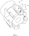
- FIG. 1 showing an isometric view of a cutting tool 10 having five cutting portions 20.
- Each cutting portion 20 has a cutting insert assembly 22 which includes an insert pocket 30 with a cutting insert 40 releasably secured therein by a fastening member 50.
- the number of cutting portions 20 is not limited to five and the shape of the cutting insert 40 is not limited to any particular shape.
- the insert pocket 30 has adjacent first and second abutment walls 52, 53, a pocket bore 54 in a pocket base 56 from which the first and second abutment walls 52, 53 extend.
- the pocket bore 54 may be threaded.
- the cutting insert 40 has a cutting insert bore 60, a first surface 62, an opposing second surface 64 and a peripheral surface 66 extending therebetween.
- the cutting insert bore 60 extends between the first and second surfaces 62, 64.
- the first and second surfaces 62, 64 meet the peripheral surface 66 at first and second peripheral edges 42, 44, respectively, at least a portion of at least one of the first and second peripheral edges 42, 44 forming a cutting edge 46. Portions of the peripheral surface 66 may abut one or both of the first and second abutment walls 52, 53.
- the cutting insert bore 60 has a first bore portion 68, a second bore portion 70, and a third bore portion 72, or intermediate bore portion, located between the first and second bore portions 68, 70.
- the first and second bore portions 68, 70 connecting with the third bore portion 72.
- the first bore portion 68 has a first bore non-abutment surface 69' adjacent the first surface 62 and first bore abutment surfaces 69" extending inwardly and downwardly from the first bore non-abutment surface 69' towards the second surface 64.
- the third bore portion 72 includes a bore plane P which is perpendicular to the bore axis B and in which the bore 60 has a non-circular cross-section.
- the bore plane P is defined by a major centerline M perpendicular to the bore axis B and a minor centerline N perpendicular to the bore axis B.
- the major and minor centerlines M, N are perpendicular to each other and define, respectively, major and minor bore dimensions D M , D N of a cross section of the third bore portion 72 taken perpendicular to the bore axis B.
- the first bore abutment surfaces 69" are symmetrical with respect to the major centerline M, this symmetry is important to ensure that unwanted effects, such as torque applied to the body of the cutting insert 40, do not occur.
- the non-circular cross section of the third bore portion 72 may be located in the bore plane P and in accordance with some embodiments may have an oval shape.
- the word oval is taken to mean a figure formed by a closed, curved line having a convex shape with two perpendicular axes that cross at a center of the figure. The figure is wider along one of the axes than along the other and diminishes in width while moving outwards from the center, along each of the two axes.
- the oval cross section of the third bore portion 72 may be elliptical in shape.
- the cross section of the third bore portion 72 taken perpendicular to the bore axis B is smaller than any other cross section of the cutting insert bore 60 taken perpendicular to the bore axis B.
- the cutting insert 40 is secured in the insert pocket 30 by the fastening member 50.
- the fastening member 50 has a fastening member head 58, a fastening member neck 57, a fastening member coupling portion 59 which may have male screw thread or any other suitable coupling means, and a fastening member axis S defining an upward to downward direction.
- the fastening member neck 57 connects between the fastening member coupling portion 59 and the fastening member head 58.
- the fastening member head 58 has a peripheral surface 79 and a fastening member head diameter D S wherein D N ⁇ D S ⁇ D M .
- the fastening member head 58 has a fastening member head upper portion 78 and a fastening member head lower portion 80 located on the fastening member head peripheral surface 79.
- the fastening member head 58 is rotationally symmetric about the fastening member axis S so that in a view along the fastening member axis S the fastening member head 58 has a circular contour.
- the fastening member head upper and lower portions 78, 80 extend from a mutual join 81.
- the join 81 is the widest portion of the fastening member head 58 so that in a view along the fastening member axis S the circular contour of the fastening member head 58 is the contour of the join 81.
- the fastening member head 58 is located in the cutting insert bore 60 with the fastening member head lower portion 80 in engagement with the first bore abutment surfaces 69".
- a large abutment area is formed between the fastening member lower portion 80 and the first bore abutment surfaces 69", therefore when the fastening member is tightened, large coupling forces are generated mainly downwards, towards the pocket base 56.
- the fastening member coupling portion 59 is received in the pocket bore 54 where it is coupled thereto in a fully coupled position.
- the fastening member coupling portion 59 may have a male screw thread and the pocket bore 54 may have a female screw thread and the fastening member coupling portion 59 may be threadingly received in the pocket bore 54.
- the fastening member head 58 when the cutting insert 40 is secured in the insert pocket 30, that is in an insert fastened position, in a top view of the cutting insert 40, the fastening member head 58 has a contour that is too large to pass through the cutting insert bore 60, thereby not allowing the fastening member head 58 to pass through the cutting insert bore 60.
- an intermediate centerline C is defined by the intersection of the minor centerline N with the fastening member 50.
- the intermediate centerline C has two intersection end points P1 and P2 (as shown in Fig. 6 and Figs. 8-12 ).
- the intermediate centerline C has an intermediate centerline dimension D C which is always less than the minor bore dimensions D N . Since the intermediate centerline C is defined by the intersection of the minor centerline N with the fastening member head 58, it is located on the minor centerline N. Although in Figs. 10 and 11 it may appear that the intermediate centerline C and the minor centerline N are coextensive, this is not the case and only seems to be the case because in the position shown in Figs. 10 and 11 the resolution of the lines in the drawing is not great enough to show that the intermediate centerline C is slightly shorter than the minor centerline N in the position shown in Fig. 6 .
- the cutting insert 40 When the fastening member coupling portion 59 is in the partially coupled position, the cutting insert 40 may be lifted from the pocket base 56 to a lifted position (see Fig. 8 ). With the cutting insert 40 in the lifted position it can be rotated about the major centerline M from a starting rotated position, as shown in Fig. 9 , while at the same time, moving it perpendicularly to the major centerline M to an intermediate rotated position as shown in Fig. 10 , until it reaches an insert removal position (see Fig. 11 ), in which in a top view of the cutting insert 40 the contour of the fastening member head 58 is small enough to pass through the cutting insert bore 60, as shown in Fig.
- the cutting insert 40 may be removed from the insert pocket 30 by lifting it off the fastening member head 58.
- a reverse sequence of the abovementioned actions is carried out.
- the variation of the intermediate centerline dimension D C illustrates how the fastening member head 50 gradually fits inside and eventually passes through the oval shape of the cross section of the third bore portion 72 (as shown in Figs 9-12 ).
- a cutting insert 140 having a cutting insert bore 160 is shown in Figs. 13 and 14 .
- the cutting insert 140 has first and second peripheral edges 142, 144, respectively, at least a portion of at least one of the first and second peripheral edges 142, 144 forming a cutting edge 146.
- the cutting insert bore 160 includes first, second and third bore portions 168, 170, 172.
- the first bore portion opens out to a first surface 162
- the second bore portion 170 opens out to a second surface 164 and the third bore portion 172 is located generally between the first and second bore portions 168, 170. In some regions of the cutting insert bore 160, the first and second bore portions 168, 170 come into contact.
- the third bore portion 172 may have some segments having the same height as a peripheral surface 166 of the cutting insert 140, in which case, the third bore portion partially opens out to at least the first surface 262. Also, if the first and second bore portions 168, 170 are identical, then the cutting insert 140 is a reversible cutting insert.
- a cutting insert 240 has first and second peripheral edges 242, 244, respectively, at least a portion of at least one of the first and second peripheral edges 242, 244 forming a cutting edge 246.
- the cutting insert 240 has a cutting insert bore 260 with only two bore portions, a first bore portion 268 opening out to a first surface 262 and a second bore portion 272 opening out to a second surface 264 of the cutting insert 240.
- the second bore portion 272 may also have some segments having the same height as a peripheral surface 266 of the cutting insert 240, in which case, the second bore portion 272 partially opens out to the first surface 262.
- a cutting insert 340 has a peripheral surface, first and second peripheral edges 342, 344, respectively, at least a portion of at least one of the first and second peripheral edges 342, 344 forming a cutting edge 346.
- the cutting insert 340 has a cutting insert bore 360 having a cylindrical first bore portion 368 opening out to a first surface 362 and a cylindrical second bore portion 370 opening out to a second surface 364. If the first and second cylindrical bore portions 368, 370 are identical, then the cutting insert 340 is a reversible cutting insert.
- a fastening member 150 may have, in addition to a first recess 151 in a fastening member head 158 for applying torque to the fastening member 150, a second recess 155 in the coupling portion 159 for applying torque to the fastening member 150.
- Such an arrangement is particularly useful when approach to the fastening member head 158 is either awkward or impossible.
- the fastening member 150 does not have to be removed, but only loosened, in order to remove and replace a cutting insert, the coupling portion 159 does not have to pass through the cutting insert through bore.
- the coupling portion 159 has a diameter which is equal to the diameter of the fastening member head 158.
- the second recess 155 may have the same dimensions as the first recess 151 thereby enabling the use of a single torque applying member for both the first and second recess 151, 155.
- the cutting insert 140, 340 or the cutting insert bore 160, 360, or both may be reflection symmetric with respect to the bore plane P defined by the major and minor centerlines M and N.
Description
- The present invention relates to the field of cutting tools, for example metal cutting tools, having cutting inserts detachably secured thereto by means of a fastener such as a screw having a screw head. More specifically, it relates to a cutting insert and the assembly and method of replacement or indexing of the cutting insert without necessitating removal of the fastener.
-
US 6,155,754 relates to a fastening arrangement in a cutting tool, having a standard cutting insert and a special locking screw, the screw head having two opposite, vertical chamfers. In this arrangement, the cutting insert can be removed without completely unscrewing the locking screw from a threaded hole in the cutting insert seat. - A drawback with this arrangement is that the screw head is not symmetrical and consequently the screw thread and the bore thread have to be designed accurately enough to ensure that after the screw is fastened, the screw head abutment surfaces are correctly oriented in order to abut and secure the cutting insert in its seat.
- Another drawback is the weakening of the screw head as a result of the removal of material due to the chamfering. Consequently, less torque can be applied to the screw head than in comparison with a non-chamfered screw head. This may lead to unpredicted, unwanted effects such as inaccuracies in locating the cutting insert, or a sudden release of the insert.
-
US 4,397,592 describes a fastening arrangement for cutting inserts having a standard cutting insert and a locking pin, asymmetrically clamping the cutting insert. This arrangement allows indexing of the cutting insert by only loosening the locking pin, lifting it until its cylindrical portion is out of its corresponding portion in the receiving hole and tilting the locking pin until it is possible to slide the cutting insert coaxially over the clamping head. - A certain drawback of this arrangement is the small and asymmetric abutment area between the locking pin clamping head and the locking face of the insert aperture. This asymmetry leads to asymmetric force distribution in the cutting insert, in comparison to the symmetric abutment. this may lead to locating inaccuracies, shortened life of the cutting insert or breaks in the cutting edges.
- Document
JP 2006 263856 A claim 1. - It is the object of the present invention to provide a cutting insert assembly for performing operations that significantly reduces or overcomes the aforementioned disadvantages.
- According to embodiments of the present invention there is provided a cutting insert and a cutting insert assembly located in a cutting portion of a cutting tool.
- In accordance with a first embodiment the cutting insert comprises the features of
claim 1 including: - a first surface, a second surface and a peripheral surface extending therebetween, the first and second surfaces meeting the peripheral surface at first and second peripheral edges, respectively, at least a portion of at least one of the first and second peripheral edges forming a cutting edge, and
- a cutting insert bore extending between the first and second surfaces and having a bore axis B, the cutting insert bore comprising:
- a first bore portion opening out to the first surface, a second bore portion opening out to the second surface and a third bore portion located between and merging with the first and second bore portions, respectively, the third bore portion including a bore plane P which is perpendicular to the bore axis B and in which the cutting insert bore has a non-circular cross-section. The third bore portion may have a major centerline M perpendicular to the bore axis B and a minor centerline N perpendicular to the bore axis B defining, respectively, major and minor dimensions DM, DN of a cross section of the third bore portion taken perpendicular to the bore axis B, wherein the cross section has an oval shape.
- In accordance with a second embodiment of the present invention, the cutting insert of the assembly is reflection symmetric with respect to a bore plane P defined by the major and minor centerlines M and N respectively.
- In accordance with another embodiment of the present invention, the cutting insert bore is reflection symmetric with respect to a bore plane P defined by the major and minor centerlines M and N respectively.
- In accordance with a third embodiment of the present invention, the cutting insert of the assembly comprises:
- a first surface, a second surface and a peripheral surface extending therebetween, the first and second surfaces meeting the peripheral surface at first and second peripheral edges, respectively, at least a portion of at least one of the first and second peripheral edges forming a cutting edge, and
- a cutting insert bore extending between the first and second surfaces and having a bore axis B, the cutting insert bore comprising:
a first bore portion opening out to the first surface and a second bore portion opening out to the second surface, the second bore portion including a bore plane P which is perpendicular to the bore axis B and in which the cutting insert bore has a non-circular cross-section. The second bore portion may have a major centerline M perpendicular to the bore axis B and a minor centerline N perpendicular to the bore axis B defining, respectively, major and minor dimensions DM, DN of a cross section of the second bore portion taken perpendicular to the bore axis B, wherein the cross section has an oval shape. - In accordance with a fourth embodiment of the present invention, the cutting insert bore has a cylindrical first bore portion and a cylindrical second bore portion.
- In accordance with the present invention there is also provided a cutting insert assembly with the features of
claim 1, comprising: - an insert pocket having a pocket base including a pocket bore;
- a fastening member having a fastening member head and a fastening member coupling portion received in the pocket bore; and
- a cutting insert, being transferable between an insert fastened position in which a fastening member head lower portion is in engagement with the first bore abutment surfaces to an insert removal position, wherein
- in the insert fastened position, in a top view of the cutting insert, the fastening member head has a contour that is too large to pass through the cutting insert bore, and
- in the insert removal position, in a top view of the cutting insert, the contour of the fastening member head is small enough to pass through the cutting insert bore.
- In accordance with the present invention, the fastening member coupling portion has a diameter which is equal to the diameter of the fastening member head.
- In accordance with embodiments of the present invention, the fastening member head has a first recess and the coupling portion has a second recess which has the same dimensions as the first recess.
- There is further provided a method for replacing or indexing the cutting insert, secured by a fastening member in an insert pocket of a cutting insert assembly of a cutting tool, the insert pocket having a pocket bore and a pocket base, the fastening member having a fastening member head and a fastening member coupling portion;
the method comprising the steps of: - a) partially removing the fastening member from the pocket bore so that the fastening member coupling portion remains coupled to the pocket bore in a partially coupled position;
- b) lifting the cutting insert from the pocket base to a lifted position;
- c) rotating the cutting insert about the major centerline M from a starting rotated position, and moving it perpendicularly to the major centerline M to an insert removal position in which, in a top view of the cutting insert, the contour of the fastening member head defines a shape that is small enough to pass through the cutting insert bore; and
- d) removing the cutting insert by lifting it off the fastening member head.
- For a better understanding of the present invention and to show how the same may be carried out in practice, reference will now be made to the accompanying drawings, in which:
-
Fig. 1 is an isometric view of a cutting tool; -
Fig. 2 is an exploded view of a cutting portion of the cutting tool shown inFig.1 ; -
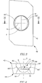
Fig. 3 is a top view of a cutting insert in accordance with embodiments of the present invention; -
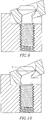
Fig. 4 is a cross-sectional view taken along line IV-IV ofFig. 3 ; -
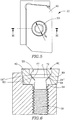
Fig. 5 is a top view of a cutting portion shown inFig. 1 with the cutting insert in an insert fastened position in the insert pocket; -
Fig. 6 is a cross-sectional view taken along line VI-VI ofFig. 5 ; -
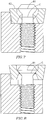
Fig. 7 is a cross-sectional view similar to that shown inFig. 6 showing the fastening member lifted; -
Fig. 8 is a cross-sectional view similar to that shown inFig. 7 showing the cutting insert in a lifted position; -
Fig. 9 is a cross-sectional view similar to that shown inFig. 8 showing the cutting insert in a starting rotated position; -
Fig. 10 is a cross-sectional view similar to that shown inFig. 6 showing the cutting insert in an intermediate rotated position; -
Fig. 11 is a cross-sectional view taken along line XI-XI ofFig. 12 , or equivalently it is a cross-sectional view similar to that shown inFig. 5 showing the cutting insert in an insert removal position allowing a head of the fastening member to pass through the cutting insert bore; -
Fig. 12 is a view of the cutting portion of the cutting tool shown inFig. 1 taken in a top view of the cutting insert indicated by the direction E inFig.11 ; -
Fig. 13 is a top view of a cutting insert in accordance with a second embodiment of the present invention; -
Fig. 14 is a cross-sectional view taken along the line XIV-XIV ofFig. 13 ; -
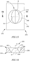
Fig. 15 is a top view of a cutting insert in accordance with a third embodiment of the present invention; -
Fig. 16 is a cross-sectional view taken along the line XVI-XVI ofFig. 15 ; -
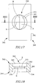
Fig. 17 is a top view of a cutting insert in accordance with a fourth embodiment of the present invention; -
Fig. 18 is a cross-sectional view taken along the line XVIII-XVIII ofFig. 17 ; and -
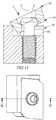
Fig. 19 is a side cross-sectional view of a fastening member according to some embodiments of the present invention. - It will be appreciated that for simplicity and clarity of illustration, elements shown in the figures have not necessarily been drawn accurately or to scale. For example, the dimensions of some of the elements may be exaggerated relative to other elements for clarity, or several physical components may be included in one functional block or element. Further, where considered appropriate, reference numerals may be repeated among the figures to indicate corresponding or analogous elements.
- In the following description, various aspects of the present invention will be described. For purposes of explanation, specific configurations and details are set forth in order to provide a thorough understanding of the present invention. However, it will also be apparent to one skilled in the art that the present invention may be practiced without the specific details presented herein. Furthermore, well-known features may be omitted or simplified in order not to obscure the present invention.
- Reference is made to the figures in general and specifically to
Fig. 1 , showing an isometric view of acutting tool 10 having five cuttingportions 20. Each cuttingportion 20 has a cuttinginsert assembly 22 which includes aninsert pocket 30 with a cuttinginsert 40 releasably secured therein by afastening member 50. The number of cuttingportions 20 is not limited to five and the shape of the cuttinginsert 40 is not limited to any particular shape. - Reference is now made to
Fig. 2 showing an exploded view of the cuttinginsert assembly 22. Theinsert pocket 30 has adjacent first andsecond abutment walls pocket base 56 from which the first andsecond abutment walls insert 40 has a cutting insert bore 60, afirst surface 62, an opposingsecond surface 64 and aperipheral surface 66 extending therebetween. The cutting insert bore 60 extends between the first andsecond surfaces second surfaces peripheral surface 66 at first and secondperipheral edges peripheral edges cutting edge 46. Portions of theperipheral surface 66 may abut one or both of the first andsecond abutment walls - Attention is now drawn to
Figs. 3 and 4 . The cutting insert bore 60 has afirst bore portion 68, asecond bore portion 70, and athird bore portion 72, or intermediate bore portion, located between the first andsecond bore portions second bore portions third bore portion 72. Thefirst bore portion 68 has a first bore non-abutment surface 69' adjacent thefirst surface 62 and first bore abutment surfaces 69" extending inwardly and downwardly from the first bore non-abutment surface 69' towards thesecond surface 64. Thethird bore portion 72 includes a bore plane P which is perpendicular to the bore axis B and in which thebore 60 has a non-circular cross-section. In some embodiments, the bore plane P is defined by a major centerline M perpendicular to the bore axis B and a minor centerline N perpendicular to the bore axis B. The major and minor centerlines M, N are perpendicular to each other and define, respectively, major and minor bore dimensions DM, DN of a cross section of thethird bore portion 72 taken perpendicular to the bore axis B. The first bore abutment surfaces 69" are symmetrical with respect to the major centerline M, this symmetry is important to ensure that unwanted effects, such as torque applied to the body of the cuttinginsert 40, do not occur. - The non-circular cross section of the
third bore portion 72 may be located in the bore plane P and in accordance with some embodiments may have an oval shape. The cross sections of the first andsecond bore portions third bore portion 72 may be elliptical in shape. The cross section of thethird bore portion 72 taken perpendicular to the bore axis B is smaller than any other cross section of the cutting insert bore 60 taken perpendicular to the bore axis B. - Attention is now drawn in addition to
Figs. 5 to 8 . The cuttinginsert 40 is secured in theinsert pocket 30 by thefastening member 50. Thefastening member 50 has afastening member head 58, afastening member neck 57, a fasteningmember coupling portion 59 which may have male screw thread or any other suitable coupling means, and a fastening member axis S defining an upward to downward direction. Thefastening member neck 57 connects between the fasteningmember coupling portion 59 and thefastening member head 58. Thefastening member head 58 has a peripheral surface 79 and a fastening member head diameter DS wherein DN<DS<DM. Thefastening member head 58 has a fastening member headupper portion 78 and a fastening member headlower portion 80 located on the fastening member head peripheral surface 79. In accordance with some embodiments, thefastening member head 58 is rotationally symmetric about the fastening member axis S so that in a view along the fastening member axis S thefastening member head 58 has a circular contour. In accordance with some embodiments, the fastening member head upper andlower portions mutual join 81. In accordance with some embodiments, thejoin 81 is the widest portion of thefastening member head 58 so that in a view along the fastening member axis S the circular contour of thefastening member head 58 is the contour of thejoin 81. - As seen in
Fig. 6 , when the cuttinginsert 40 is secured in theinsert pocket 30, that is, in an insert fastened position, thefastening member head 58 is located in the cutting insert bore 60 with the fastening member headlower portion 80 in engagement with the first bore abutment surfaces 69". In this position, a large abutment area is formed between the fastening memberlower portion 80 and the first bore abutment surfaces 69", therefore when the fastening member is tightened, large coupling forces are generated mainly downwards, towards thepocket base 56. The fasteningmember coupling portion 59 is received in the pocket bore 54 where it is coupled thereto in a fully coupled position. In accordance with some embodiments the fasteningmember coupling portion 59 may have a male screw thread and the pocket bore 54 may have a female screw thread and the fasteningmember coupling portion 59 may be threadingly received in the pocket bore 54. As can be seen fromFig. 5 , and understood fromFig. 6 , when the cuttinginsert 40 is secured in theinsert pocket 30, that is in an insert fastened position, in a top view of the cuttinginsert 40, thefastening member head 58 has a contour that is too large to pass through the cutting insert bore 60, thereby not allowing thefastening member head 58 to pass through the cutting insert bore 60. - For the
fastening member 50 an intermediate centerline C is defined by the intersection of the minor centerline N with thefastening member 50. The intermediate centerline C has two intersection end points P1 and P2 (as shown inFig. 6 andFigs. 8-12 ). The intermediate centerline C has an intermediate centerline dimension DC which is always less than the minor bore dimensions DN. Since the intermediate centerline C is defined by the intersection of the minor centerline N with thefastening member head 58, it is located on the minor centerline N. Although inFigs. 10 and11 it may appear that the intermediate centerline C and the minor centerline N are coextensive, this is not the case and only seems to be the case because in the position shown inFigs. 10 and11 the resolution of the lines in the drawing is not great enough to show that the intermediate centerline C is slightly shorter than the minor centerline N in the position shown inFig. 6 . - In order to replace or index the cutting
insert 40, it is not necessary, as will be shown below, to remove thefastening member 50 completely from the pocket bore 54. In order to replace or index the cuttinginsert 40 it is sufficient to partially remove thefastening member 50 from the pocket bore 54 so that the fasteningmember coupling portion 59 remains coupled to the pocket bore 54 in a partially coupled position (seeFig. 7-11 ). When the fasteningmember coupling portion 59 is in the partially coupled position, thefastening member head 58 is further removed from thepocket base 56 than when the fasteningmember coupling portion 59 is in the fully coupled position (as shown inFig. 6 ). When the fasteningmember coupling portion 59 is in the partially coupled position, the cuttinginsert 40 may be lifted from thepocket base 56 to a lifted position (seeFig. 8 ). With the cuttinginsert 40 in the lifted position it can be rotated about the major centerline M from a starting rotated position, as shown inFig. 9 , while at the same time, moving it perpendicularly to the major centerline M to an intermediate rotated position as shown inFig. 10 , until it reaches an insert removal position (seeFig. 11 ), in which in a top view of the cuttinginsert 40 the contour of thefastening member head 58 is small enough to pass through the cutting insert bore 60, as shown inFig. 12 , thereby allowing thefastening member head 58 to pass through the cutting insert bore 60. In the insert removal position the cuttinginsert 40 may be removed from theinsert pocket 30 by lifting it off thefastening member head 58. In order to install a replacement cutting insert while the fasteningmember coupling portion 59 is clamped in the pocket bore 54, a reverse sequence of the abovementioned actions is carried out. - The variation of the intermediate centerline dimension DC, during the above mentioned rotation of the cutting
insert 40, illustrates how thefastening member head 50 gradually fits inside and eventually passes through the oval shape of the cross section of the third bore portion 72 (as shown inFigs 9-12 ). - According to another embodiment, a cutting
insert 140 having a cutting insert bore 160 is shown inFigs. 13 and 14 . The cuttinginsert 140 has first and secondperipheral edges peripheral edges cutting edge 146. The cutting insert bore 160 includes first, second andthird bore portions first surface 162, thesecond bore portion 170 opens out to asecond surface 164 and thethird bore portion 172 is located generally between the first andsecond bore portions second bore portions third bore portion 172 may have some segments having the same height as aperipheral surface 166 of the cuttinginsert 140, in which case, the third bore portion partially opens out to at least thefirst surface 262. Also, if the first andsecond bore portions insert 140 is a reversible cutting insert. - According to another embodiment shown in
Figs. 15 and 16 , a cuttinginsert 240 has first and secondperipheral edges peripheral edges cutting edge 246. The cuttinginsert 240 has a cutting insert bore 260 with only two bore portions, afirst bore portion 268 opening out to afirst surface 262 and asecond bore portion 272 opening out to asecond surface 264 of the cuttinginsert 240. Thesecond bore portion 272 may also have some segments having the same height as aperipheral surface 266 of the cuttinginsert 240, in which case, thesecond bore portion 272 partially opens out to thefirst surface 262. - According to yet another embodiment shown in
Figs. 17 and 18 , a cuttinginsert 340 has a peripheral surface, first and secondperipheral edges peripheral edges cutting edge 346. The cuttinginsert 340 has a cutting insert bore 360 having a cylindricalfirst bore portion 368 opening out to afirst surface 362 and a cylindricalsecond bore portion 370 opening out to asecond surface 364. If the first and secondcylindrical bore portions insert 340 is a reversible cutting insert. - According to some embodiments as shown in
Fig. 19 , afastening member 150 may have, in addition to afirst recess 151 in afastening member head 158 for applying torque to thefastening member 150, asecond recess 155 in thecoupling portion 159 for applying torque to thefastening member 150. Such an arrangement is particularly useful when approach to thefastening member head 158 is either awkward or impossible. Moreover, since, in accordance with the present invention, thefastening member 150 does not have to be removed, but only loosened, in order to remove and replace a cutting insert, thecoupling portion 159 does not have to pass through the cutting insert through bore. Consequently, thecoupling portion 159 has a diameter which is equal to the diameter of thefastening member head 158. This being the case, thesecond recess 155 may have the same dimensions as thefirst recess 151 thereby enabling the use of a single torque applying member for both the first andsecond recess - In accordance with embodiments of the present invention, the cutting
insert
Claims (5)
- A cutting insert assembly (22) comprising:an insert pocket (30) having a pocket base (56) including a pocket bore (54);a fastening member (50) having a fastening member head (58) and a fastening member coupling portion (59) received in the pocket bore (54); anda cutting insert (40, 140, 340) comprising:a first surface (62, 162, 362), a second surface (64, 164, 364) and a peripheral surface (66, 166, 366) extending therebetween, the first and second surfaces (62, 162, 362, 64, 164, 364) meeting the peripheral surface (66, 166, 366) at first and second peripheral edges (42, 142, 342, 44, 144, 344), respectively, at least a portion of at least one of the first and second peripheral edges (42, 142, 342, 44, 144, 344) forming a cutting edge (46, 146, 346), anda cutting insert bore (60, 160, 360) extending between the first and second surfaces and having a bore axis B, the cutting insert bore comprising:a first bore portion (68, 168, 368) opening out to the first surface (62, 162, 362),a second bore portion (70, 170, 370) opening out to the second surface (64, 164, 364), anda third bore portion (72, 172, 372) located between and merging with the first and second bore portions, (68, 168, 368, 70, 170, 370), respectively, the third bore portion (72, 172, 372) having a major centerline M perpendicular to the bore axis B and a minor centerline N perpendicular to the bore axis B defining, respectively, major and minor dimensions DM, DN of a cross section of the third bore portion (72, 172, 372) taken perpendicular to the bore axis B, wherein the cross section has an oval shape:the cutting insert (40, 140. 340), being transferable between an insert fastened position in which a fastening member head lower portion (80) is in engagement with the first bore abutment surfaces (69") to an insert removal position, whereinin the insert fastened position, in a top view of the cutting insert (40, 140, 340), the fastening member head (58) has a contour that is too large to pass through the cutting insert bore (60, 160, 360), andin the insert removal position, in a top view of the cutting insert (40, 140, 340), the contour of the fastening member head (58) is small enough to pass through the cutting insert bore (60, 160, 360), characterised in that the fastening member coupling portion (159) has a diameter which is equal to the diameter of the fastening member head (158).
- A cutting insert assembly (22) according to claim 1, wherein the bore plane P is defined by the major and minor centerlines M and N; and
the cutting insert (140, 340) is reflection symmetric with respect to the bore plane P. - The cutting insert assembly (22) according to claim 1, wherein the fastening member head (158) has a first recess (151) and the coupling portion (159) has a second recess (155) which has the same dimensions as the first recess (151).
- The cutting insert assembly (22) according to claim 1 or 2, wherein:the bore plane P is defined by the major and minor centerlines M and N; andthe cutting insert bore (160, 360) is reflection symmetric with respect to the bore plane P.
- The cutting insert assembly (22) according to claim 1, wherein the cutting insert bore (360) has a cylindrical first bore portion (368) and a cylindrical second bore portion (370).
Priority Applications (1)
| Application Number | Priority Date | Filing Date | Title |
|---|---|---|---|
| PL10720825T PL2424699T3 (en) | 2009-04-26 | 2010-03-28 | Cutting insert and cutting insert assembly |
Applications Claiming Priority (2)
| Application Number | Priority Date | Filing Date | Title |
|---|---|---|---|
| IL198376A IL198376A (en) | 2009-04-26 | 2009-04-26 | Cutting insert and cutting insert assembly |
| PCT/IL2010/000263 WO2010125554A1 (en) | 2009-04-26 | 2010-03-28 | Cutting insert and cutting insert assembly |
Publications (2)
| Publication Number | Publication Date |
|---|---|
| EP2424699A1 EP2424699A1 (en) | 2012-03-07 |
| EP2424699B1 true EP2424699B1 (en) | 2020-03-25 |
Family
ID=42113734
Family Applications (1)
| Application Number | Title | Priority Date | Filing Date |
|---|---|---|---|
| EP10720825.8A Active EP2424699B1 (en) | 2009-04-26 | 2010-03-28 | Cutting insert and cutting insert assembly |
Country Status (14)
| Country | Link |
|---|---|
| US (1) | US8747031B2 (en) |
| EP (1) | EP2424699B1 (en) |
| JP (2) | JP5965836B2 (en) |
| KR (1) | KR20120013344A (en) |
| CN (1) | CN102438785B (en) |
| BR (1) | BRPI1013979B1 (en) |
| CA (1) | CA2758535C (en) |
| ES (1) | ES2780149T3 (en) |
| IL (1) | IL198376A (en) |
| PL (1) | PL2424699T3 (en) |
| PT (1) | PT2424699T (en) |
| RU (1) | RU2518835C2 (en) |
| TW (1) | TW201043360A (en) |
| WO (1) | WO2010125554A1 (en) |
Families Citing this family (14)
| Publication number | Priority date | Publication date | Assignee | Title |
|---|---|---|---|---|
| USRE46858E1 (en) | 2009-02-27 | 2018-05-22 | No Screw Ltd. | Cutting tool, cutting tool holder and cutting insert therefor |
| BR112014002411B1 (en) * | 2011-08-02 | 2020-10-13 | Iscar Ltd | insert and cutting tool |
| CN202291575U (en) * | 2011-10-12 | 2012-07-04 | 益壮企业有限公司 | T-shaped milling cutter |
| CN102601439A (en) * | 2011-12-19 | 2012-07-25 | 株洲钻石切削刀具股份有限公司 | Milling cutter |
| US8746115B2 (en) * | 2012-01-09 | 2014-06-10 | Iscar, Ltd. | Cutting insert having hole orientation indicia and method for making thereof |
| JP6227533B2 (en) * | 2012-10-10 | 2017-11-08 | イスカーリミテッド | Cutting insert of cutting tool assembly for chip removal, cutting body, and clamping mechanism |
| CN105682834B (en) | 2013-09-03 | 2018-07-03 | 诺斯库有限公司 | For the installing mechanism of cutting tip, cutting tip and the cutting element using the blade |
| US20160121406A1 (en) | 2014-10-29 | 2016-05-05 | Illinois Tool Works Inc. | Interchangeable cutting inserts and methods associated with the same |
| CN104400358B (en) * | 2014-11-24 | 2017-08-11 | 马鞍山市恒利达机械刀片有限公司 | The processing method that tool rest is combined in a kind of double millings of mechanical quick-replaceable type aluminium ingot |
| US9962774B2 (en) * | 2014-12-08 | 2018-05-08 | The Boeing Company | Cutting tool |
| US10307833B2 (en) | 2015-02-04 | 2019-06-04 | No Screw Ltd. | Cutting tool comprising a cutting tool holder and a cutting insert therefor |
| US10307832B2 (en) | 2015-04-30 | 2019-06-04 | No Screw Ltd. | Dynamic clamping mechanism |
| EP3668667A1 (en) * | 2017-08-18 | 2020-06-24 | Illinois Tool Works Inc. | Interchangeable cutting inserts and methods associated with the same |
| EP3717159A1 (en) * | 2017-11-30 | 2020-10-07 | Iscar Ltd. | Modular turning tool having a replaceable adaptor |
Citations (1)
| Publication number | Priority date | Publication date | Assignee | Title |
|---|---|---|---|---|
| JP2006263856A (en) * | 2005-03-24 | 2006-10-05 | Tungaloy Corp | Throw-away type cutting tool |
Family Cites Families (21)
| Publication number | Priority date | Publication date | Assignee | Title |
|---|---|---|---|---|
| US3654682A (en) * | 1970-09-01 | 1972-04-11 | Edward H Newbould | Tool holder |
| US3740807A (en) * | 1972-02-25 | 1973-06-26 | Metal Cutting Tools Inc | Inserted blade cutting tool with locking pin |
| US3913197A (en) * | 1973-11-19 | 1975-10-21 | Heinz K Wolf | Positive lock insert |
| DE2906148A1 (en) * | 1979-02-17 | 1980-08-28 | Walter Gmbh Montanwerke | CUTTING TOOL WITH REPLACEMENT INSERT |
| US4397592A (en) * | 1980-11-10 | 1983-08-09 | Kennametal Inc. | Insert holder and method of holding |
| SU1255287A1 (en) * | 1985-04-03 | 1986-09-07 | Medvedev Mikhail D | Assembled cutting tool |
| SU1542700A1 (en) * | 1987-11-12 | 1990-02-15 | Краматорский Индустриальный Институт | Two-sided cutting bit |
| JPH02135115U (en) * | 1989-04-14 | 1990-11-09 | ||
| US5039259A (en) * | 1990-06-04 | 1991-08-13 | Duncan Thomas E | Diamond edge milling tool |
| SE9003705L (en) * | 1990-11-21 | 1992-05-22 | Seco Tools Ab | SKAERVERKTYG |
| SE505726C2 (en) | 1995-02-27 | 1997-10-06 | Sandvik Ab | Clamping device for cutting plates |
| JP2003165004A (en) * | 2001-11-29 | 2003-06-10 | Ngk Spark Plug Co Ltd | Turning tool |
| JP2004167635A (en) * | 2002-11-20 | 2004-06-17 | Mitsubishi Materials Corp | Mechanism for clamping throwaway chip, and throwaway tip used for the same |
| JP2004261937A (en) * | 2003-03-04 | 2004-09-24 | Kyocera Corp | Throw away type cutting tool |
| US7771142B2 (en) * | 2003-05-09 | 2010-08-10 | Kennametal Inc. | Cutting insert with elliptical cutting edge |
| JP4639862B2 (en) * | 2004-03-26 | 2011-02-23 | 三菱マテリアル株式会社 | Claw mechanism for throw-away tip |
| KR100625838B1 (en) * | 2004-11-16 | 2006-09-20 | 대구텍 주식회사 | Insert Tip |
| SE528710C2 (en) * | 2005-06-01 | 2007-01-30 | Sandvik Intellectual Property | Indexable cutter with the coupling means arranged on a release surface |
| SE530374C2 (en) * | 2006-05-23 | 2008-05-20 | Pramet Tools Sro | Cutting insert and cutting tool where the clamping surface of the clamping hole is in the form of an elliptical cone |
| US7959383B2 (en) * | 2006-09-06 | 2011-06-14 | Taegutec Ltd. | Cutting insert and cutting tool therewith |
| EP2139633B1 (en) * | 2007-04-26 | 2017-05-31 | Taegu TEC India P.LTD. | Cutting insert for a milling cutter |
-
2009
- 2009-04-26 IL IL198376A patent/IL198376A/en active IP Right Grant
-
2010
- 2010-03-25 TW TW099108944A patent/TW201043360A/en unknown
- 2010-03-28 RU RU2011148103/02A patent/RU2518835C2/en active
- 2010-03-28 PL PL10720825T patent/PL2424699T3/en unknown
- 2010-03-28 CA CA2758535A patent/CA2758535C/en active Active
- 2010-03-28 PT PT107208258T patent/PT2424699T/en unknown
- 2010-03-28 WO PCT/IL2010/000263 patent/WO2010125554A1/en active Application Filing
- 2010-03-28 ES ES10720825T patent/ES2780149T3/en active Active
- 2010-03-28 KR KR1020117025183A patent/KR20120013344A/en not_active Application Discontinuation
- 2010-03-28 BR BRPI1013979-6A patent/BRPI1013979B1/en active IP Right Grant
- 2010-03-28 EP EP10720825.8A patent/EP2424699B1/en active Active
- 2010-03-28 CN CN201080018247.6A patent/CN102438785B/en active Active
- 2010-03-28 JP JP2012506642A patent/JP5965836B2/en active Active
- 2010-04-22 US US12/765,604 patent/US8747031B2/en active Active
-
2014
- 2014-12-12 JP JP2014252235A patent/JP2015062993A/en active Pending
Patent Citations (1)
| Publication number | Priority date | Publication date | Assignee | Title |
|---|---|---|---|---|
| JP2006263856A (en) * | 2005-03-24 | 2006-10-05 | Tungaloy Corp | Throw-away type cutting tool |
Also Published As
| Publication number | Publication date |
|---|---|
| WO2010125554A1 (en) | 2010-11-04 |
| US8747031B2 (en) | 2014-06-10 |
| BRPI1013979A2 (en) | 2016-04-05 |
| PL2424699T3 (en) | 2020-07-13 |
| TW201043360A (en) | 2010-12-16 |
| RU2518835C2 (en) | 2014-06-10 |
| CN102438785A (en) | 2012-05-02 |
| JP2015062993A (en) | 2015-04-09 |
| JP2012524666A (en) | 2012-10-18 |
| PT2424699T (en) | 2020-05-14 |
| IL198376A (en) | 2013-04-30 |
| CN102438785B (en) | 2014-06-11 |
| EP2424699A1 (en) | 2012-03-07 |
| IL198376A0 (en) | 2010-02-17 |
| RU2011148103A (en) | 2013-06-10 |
| ES2780149T3 (en) | 2020-08-24 |
| KR20120013344A (en) | 2012-02-14 |
| US20100272522A1 (en) | 2010-10-28 |
| CA2758535C (en) | 2016-04-12 |
| CA2758535A1 (en) | 2010-11-04 |
| JP5965836B2 (en) | 2016-08-10 |
| BRPI1013979B1 (en) | 2020-08-11 |
Similar Documents
| Publication | Publication Date | Title |
|---|---|---|
| EP2424699B1 (en) | Cutting insert and cutting insert assembly | |
| US8740510B2 (en) | Cutting insert and cutting tool, and cutting method using the same | |
| US8337123B2 (en) | Cutting insert, cutting tool, and cutting method using the cutting tool | |
| KR101052708B1 (en) | Indexable cutting inserts with chip breakers | |
| EP1791671B1 (en) | A milling tool, a cutting insert for milling tool as well as a solid milling tool | |
| KR101315627B1 (en) | A tool and a cutting insert for chip removing machining | |
| EP1736263B1 (en) | Clamping structure for throwaway chip | |
| EP1539413B1 (en) | Cutting insert and method | |
| EP1297921B1 (en) | Turning insert | |
| EP3241638B1 (en) | Cutting insert, tool body, and cutting tool | |
| WO2016147493A1 (en) | Cutting insert, cutting insert group, and blade tip replacement cutting tool | |
| CZ301959B6 (en) | Indexable cutting insert for milling cutter and milling cutter comprising such cutting insert | |
| EP2532460B1 (en) | Cutting edge replacement type groove forming tool and end face groove forming method | |
| WO2018042957A1 (en) | Cutting insert | |
| JP4639881B2 (en) | Throw-away cutting tool | |
| KR101444470B1 (en) | Cutting tool | |
| JP6528781B2 (en) | Cutting inserts, tool bodies and cutting tools | |
| EP3025814B1 (en) | A milling insert and a milling tool | |
| US6648560B2 (en) | Cutting insert | |
| CN214161431U (en) | Cutter fixer for turning | |
| RU2779738C2 (en) | Unilateral three-way indexable cutting insert for milling, having large ratio of void volume to material volume, and milling cutter with insert for it | |
| EP4074442A1 (en) | Cutting insert and cutting tool | |
| KR20220130718A (en) | Rectangular-shaped inserts for bar peeling and insert-holder tools therefor | |
| JP2002210603A (en) | Throwaway tip |
Legal Events
| Date | Code | Title | Description |
|---|---|---|---|
| PUAI | Public reference made under article 153(3) epc to a published international application that has entered the european phase |
Free format text: ORIGINAL CODE: 0009012 |
|
| 17P | Request for examination filed |
Effective date: 20111123 |
|
| AK | Designated contracting states |
Kind code of ref document: A1 Designated state(s): AT BE BG CH CY CZ DE DK EE ES FI FR GB GR HR HU IE IS IT LI LT LU LV MC MK MT NL NO PL PT RO SE SI SK SM TR |
|
| DAX | Request for extension of the european patent (deleted) | ||
| 17Q | First examination report despatched |
Effective date: 20160810 |
|
| STAA | Information on the status of an ep patent application or granted ep patent |
Free format text: STATUS: EXAMINATION IS IN PROGRESS |
|
| REG | Reference to a national code |
Ref country code: DE Ref legal event code: R079 Ref document number: 602010063619 Country of ref document: DE Free format text: PREVIOUS MAIN CLASS: B23C0005200000 Ipc: B23B0027160000 |
|
| GRAP | Despatch of communication of intention to grant a patent |
Free format text: ORIGINAL CODE: EPIDOSNIGR1 |
|
| STAA | Information on the status of an ep patent application or granted ep patent |
Free format text: STATUS: GRANT OF PATENT IS INTENDED |
|
| RIC1 | Information provided on ipc code assigned before grant |
Ipc: B23B 27/16 20060101AFI20190405BHEP |
|
| INTG | Intention to grant announced |
Effective date: 20190502 |
|
| GRAS | Grant fee paid |
Free format text: ORIGINAL CODE: EPIDOSNIGR3 |
|
| GRAJ | Information related to disapproval of communication of intention to grant by the applicant or resumption of examination proceedings by the epo deleted |
Free format text: ORIGINAL CODE: EPIDOSDIGR1 |
|
| GRAL | Information related to payment of fee for publishing/printing deleted |
Free format text: ORIGINAL CODE: EPIDOSDIGR3 |
|
| STAA | Information on the status of an ep patent application or granted ep patent |
Free format text: STATUS: EXAMINATION IS IN PROGRESS |
|
| GRAP | Despatch of communication of intention to grant a patent |
Free format text: ORIGINAL CODE: EPIDOSNIGR1 |
|
| STAA | Information on the status of an ep patent application or granted ep patent |
Free format text: STATUS: GRANT OF PATENT IS INTENDED |
|
| INTC | Intention to grant announced (deleted) | ||
| INTG | Intention to grant announced |
Effective date: 20191018 |
|
| GRAA | (expected) grant |
Free format text: ORIGINAL CODE: 0009210 |
|
| STAA | Information on the status of an ep patent application or granted ep patent |
Free format text: STATUS: THE PATENT HAS BEEN GRANTED |
|
| AK | Designated contracting states |
Kind code of ref document: B1 Designated state(s): AT BE BG CH CY CZ DE DK EE ES FI FR GB GR HR HU IE IS IT LI LT LU LV MC MK MT NL NO PL PT RO SE SI SK SM TR |
|
| REG | Reference to a national code |
Ref country code: GB Ref legal event code: FG4D |
|
| REG | Reference to a national code |
Ref country code: AT Ref legal event code: REF Ref document number: 1248001 Country of ref document: AT Kind code of ref document: T Effective date: 20200415 Ref country code: IE Ref legal event code: FG4D |
|
| REG | Reference to a national code |
Ref country code: DE Ref legal event code: R096 Ref document number: 602010063619 Country of ref document: DE |
|
| REG | Reference to a national code |
Ref country code: SE Ref legal event code: TRGR |
|
| REG | Reference to a national code |
Ref country code: PT Ref legal event code: SC4A Ref document number: 2424699 Country of ref document: PT Date of ref document: 20200514 Kind code of ref document: T Free format text: AVAILABILITY OF NATIONAL TRANSLATION Effective date: 20200506 |
|
| PG25 | Lapsed in a contracting state [announced via postgrant information from national office to epo] |
Ref country code: FI Free format text: LAPSE BECAUSE OF FAILURE TO SUBMIT A TRANSLATION OF THE DESCRIPTION OR TO PAY THE FEE WITHIN THE PRESCRIBED TIME-LIMIT Effective date: 20200325 Ref country code: NO Free format text: LAPSE BECAUSE OF FAILURE TO SUBMIT A TRANSLATION OF THE DESCRIPTION OR TO PAY THE FEE WITHIN THE PRESCRIBED TIME-LIMIT Effective date: 20200625 |
|
| REG | Reference to a national code |
Ref country code: ES Ref legal event code: FG2A Ref document number: 2780149 Country of ref document: ES Kind code of ref document: T3 Effective date: 20200824 |
|
| PG25 | Lapsed in a contracting state [announced via postgrant information from national office to epo] |
Ref country code: GR Free format text: LAPSE BECAUSE OF FAILURE TO SUBMIT A TRANSLATION OF THE DESCRIPTION OR TO PAY THE FEE WITHIN THE PRESCRIBED TIME-LIMIT Effective date: 20200626 Ref country code: BG Free format text: LAPSE BECAUSE OF FAILURE TO SUBMIT A TRANSLATION OF THE DESCRIPTION OR TO PAY THE FEE WITHIN THE PRESCRIBED TIME-LIMIT Effective date: 20200625 Ref country code: HR Free format text: LAPSE BECAUSE OF FAILURE TO SUBMIT A TRANSLATION OF THE DESCRIPTION OR TO PAY THE FEE WITHIN THE PRESCRIBED TIME-LIMIT Effective date: 20200325 Ref country code: LV Free format text: LAPSE BECAUSE OF FAILURE TO SUBMIT A TRANSLATION OF THE DESCRIPTION OR TO PAY THE FEE WITHIN THE PRESCRIBED TIME-LIMIT Effective date: 20200325 |
|
| REG | Reference to a national code |
Ref country code: NL Ref legal event code: MP Effective date: 20200325 |
|
| REG | Reference to a national code |
Ref country code: LT Ref legal event code: MG4D |
|
| PG25 | Lapsed in a contracting state [announced via postgrant information from national office to epo] |
Ref country code: NL Free format text: LAPSE BECAUSE OF FAILURE TO SUBMIT A TRANSLATION OF THE DESCRIPTION OR TO PAY THE FEE WITHIN THE PRESCRIBED TIME-LIMIT Effective date: 20200325 |
|
| REG | Reference to a national code |
Ref country code: AT Ref legal event code: UEP Ref document number: 1248001 Country of ref document: AT Kind code of ref document: T Effective date: 20200325 |
|
| PG25 | Lapsed in a contracting state [announced via postgrant information from national office to epo] |
Ref country code: EE Free format text: LAPSE BECAUSE OF FAILURE TO SUBMIT A TRANSLATION OF THE DESCRIPTION OR TO PAY THE FEE WITHIN THE PRESCRIBED TIME-LIMIT Effective date: 20200325 Ref country code: SM Free format text: LAPSE BECAUSE OF FAILURE TO SUBMIT A TRANSLATION OF THE DESCRIPTION OR TO PAY THE FEE WITHIN THE PRESCRIBED TIME-LIMIT Effective date: 20200325 Ref country code: LT Free format text: LAPSE BECAUSE OF FAILURE TO SUBMIT A TRANSLATION OF THE DESCRIPTION OR TO PAY THE FEE WITHIN THE PRESCRIBED TIME-LIMIT Effective date: 20200325 Ref country code: SK Free format text: LAPSE BECAUSE OF FAILURE TO SUBMIT A TRANSLATION OF THE DESCRIPTION OR TO PAY THE FEE WITHIN THE PRESCRIBED TIME-LIMIT Effective date: 20200325 Ref country code: RO Free format text: LAPSE BECAUSE OF FAILURE TO SUBMIT A TRANSLATION OF THE DESCRIPTION OR TO PAY THE FEE WITHIN THE PRESCRIBED TIME-LIMIT Effective date: 20200325 Ref country code: IS Free format text: LAPSE BECAUSE OF FAILURE TO SUBMIT A TRANSLATION OF THE DESCRIPTION OR TO PAY THE FEE WITHIN THE PRESCRIBED TIME-LIMIT Effective date: 20200725 |
|
| REG | Reference to a national code |
Ref country code: CH Ref legal event code: PL |
|
| REG | Reference to a national code |
Ref country code: BE Ref legal event code: MM Effective date: 20200331 |
|
| PG25 | Lapsed in a contracting state [announced via postgrant information from national office to epo] |
Ref country code: MC Free format text: LAPSE BECAUSE OF FAILURE TO SUBMIT A TRANSLATION OF THE DESCRIPTION OR TO PAY THE FEE WITHIN THE PRESCRIBED TIME-LIMIT Effective date: 20200325 Ref country code: LU Free format text: LAPSE BECAUSE OF NON-PAYMENT OF DUE FEES Effective date: 20200328 |
|
| REG | Reference to a national code |
Ref country code: DE Ref legal event code: R097 Ref document number: 602010063619 Country of ref document: DE |
|
| PG25 | Lapsed in a contracting state [announced via postgrant information from national office to epo] |
Ref country code: LI Free format text: LAPSE BECAUSE OF NON-PAYMENT OF DUE FEES Effective date: 20200331 Ref country code: DK Free format text: LAPSE BECAUSE OF FAILURE TO SUBMIT A TRANSLATION OF THE DESCRIPTION OR TO PAY THE FEE WITHIN THE PRESCRIBED TIME-LIMIT Effective date: 20200325 Ref country code: CH Free format text: LAPSE BECAUSE OF NON-PAYMENT OF DUE FEES Effective date: 20200331 Ref country code: IE Free format text: LAPSE BECAUSE OF NON-PAYMENT OF DUE FEES Effective date: 20200328 |
|
| PLBE | No opposition filed within time limit |
Free format text: ORIGINAL CODE: 0009261 |
|
| STAA | Information on the status of an ep patent application or granted ep patent |
Free format text: STATUS: NO OPPOSITION FILED WITHIN TIME LIMIT |
|
| PG25 | Lapsed in a contracting state [announced via postgrant information from national office to epo] |
Ref country code: BE Free format text: LAPSE BECAUSE OF NON-PAYMENT OF DUE FEES Effective date: 20200331 |
|
| 26N | No opposition filed |
Effective date: 20210112 |
|
| PG25 | Lapsed in a contracting state [announced via postgrant information from national office to epo] |
Ref country code: SI Free format text: LAPSE BECAUSE OF FAILURE TO SUBMIT A TRANSLATION OF THE DESCRIPTION OR TO PAY THE FEE WITHIN THE PRESCRIBED TIME-LIMIT Effective date: 20200325 |
|
| PG25 | Lapsed in a contracting state [announced via postgrant information from national office to epo] |
Ref country code: MT Free format text: LAPSE BECAUSE OF FAILURE TO SUBMIT A TRANSLATION OF THE DESCRIPTION OR TO PAY THE FEE WITHIN THE PRESCRIBED TIME-LIMIT Effective date: 20200325 Ref country code: CY Free format text: LAPSE BECAUSE OF FAILURE TO SUBMIT A TRANSLATION OF THE DESCRIPTION OR TO PAY THE FEE WITHIN THE PRESCRIBED TIME-LIMIT Effective date: 20200325 |
|
| PG25 | Lapsed in a contracting state [announced via postgrant information from national office to epo] |
Ref country code: MK Free format text: LAPSE BECAUSE OF FAILURE TO SUBMIT A TRANSLATION OF THE DESCRIPTION OR TO PAY THE FEE WITHIN THE PRESCRIBED TIME-LIMIT Effective date: 20200325 |
|
| PGFP | Annual fee paid to national office [announced via postgrant information from national office to epo] |
Ref country code: FR Payment date: 20230217 Year of fee payment: 14 Ref country code: CZ Payment date: 20230220 Year of fee payment: 14 Ref country code: AT Payment date: 20230206 Year of fee payment: 14 |
|
| PGFP | Annual fee paid to national office [announced via postgrant information from national office to epo] |
Ref country code: TR Payment date: 20230303 Year of fee payment: 14 Ref country code: SE Payment date: 20230210 Year of fee payment: 14 Ref country code: PT Payment date: 20230124 Year of fee payment: 14 Ref country code: PL Payment date: 20230119 Year of fee payment: 14 Ref country code: IT Payment date: 20230116 Year of fee payment: 14 Ref country code: GB Payment date: 20230213 Year of fee payment: 14 Ref country code: DE Payment date: 20230206 Year of fee payment: 14 |
|
| PGFP | Annual fee paid to national office [announced via postgrant information from national office to epo] |
Ref country code: ES Payment date: 20230425 Year of fee payment: 14 |