KR20120013344A - Cutting insert and cutting insert assembly - Google Patents
Cutting insert and cutting insert assembly Download PDFInfo
- Publication number
- KR20120013344A KR20120013344A KR1020117025183A KR20117025183A KR20120013344A KR 20120013344 A KR20120013344 A KR 20120013344A KR 1020117025183 A KR1020117025183 A KR 1020117025183A KR 20117025183 A KR20117025183 A KR 20117025183A KR 20120013344 A KR20120013344 A KR 20120013344A
- Authority
- KR
- South Korea
- Prior art keywords
- bore
- cutting insert
- fastening member
- cutting
- insert
- Prior art date
Links
- 230000002093 peripheral effect Effects 0.000 claims abstract description 54
- 238000000034 method Methods 0.000 claims description 12
- 230000008878 coupling Effects 0.000 claims description 7
- 238000010168 coupling process Methods 0.000 claims description 7
- 238000005859 coupling reaction Methods 0.000 claims description 7
- 230000002441 reversible effect Effects 0.000 description 3
- 240000006829 Ficus sundaica Species 0.000 description 1
- 238000000429 assembly Methods 0.000 description 1
- 230000000712 assembly Effects 0.000 description 1
- 230000007423 decrease Effects 0.000 description 1
- 230000000694 effects Effects 0.000 description 1
- 239000000463 material Substances 0.000 description 1
- 239000002184 metal Substances 0.000 description 1
- 238000012986 modification Methods 0.000 description 1
- 230000004048 modification Effects 0.000 description 1
- 238000004904 shortening Methods 0.000 description 1
- 230000003313 weakening effect Effects 0.000 description 1
Images


Classifications
-
- B—PERFORMING OPERATIONS; TRANSPORTING
- B23—MACHINE TOOLS; METAL-WORKING NOT OTHERWISE PROVIDED FOR
- B23B—TURNING; BORING
- B23B27/00—Tools for turning or boring machines; Tools of a similar kind in general; Accessories therefor
- B23B27/14—Cutting tools of which the bits or tips or cutting inserts are of special material
- B23B27/16—Cutting tools of which the bits or tips or cutting inserts are of special material with exchangeable cutting bits or cutting inserts, e.g. able to be clamped
-
- B—PERFORMING OPERATIONS; TRANSPORTING
- B23—MACHINE TOOLS; METAL-WORKING NOT OTHERWISE PROVIDED FOR
- B23C—MILLING
- B23C5/00—Milling-cutters
- B23C5/16—Milling-cutters characterised by physical features other than shape
- B23C5/20—Milling-cutters characterised by physical features other than shape with removable cutter bits or teeth or cutting inserts
- B23C5/202—Plate-like cutting inserts with special form
-
- B—PERFORMING OPERATIONS; TRANSPORTING
- B23—MACHINE TOOLS; METAL-WORKING NOT OTHERWISE PROVIDED FOR
- B23C—MILLING
- B23C5/00—Milling-cutters
- B23C5/16—Milling-cutters characterised by physical features other than shape
- B23C5/20—Milling-cutters characterised by physical features other than shape with removable cutter bits or teeth or cutting inserts
- B23C5/22—Securing arrangements for bits or teeth or cutting inserts
- B23C5/2204—Securing arrangements for bits or teeth or cutting inserts with cutting inserts clamped against the walls of the recess in the cutter body by a clamping member acting upon the wall of a hole in the insert
- B23C5/2208—Securing arrangements for bits or teeth or cutting inserts with cutting inserts clamped against the walls of the recess in the cutter body by a clamping member acting upon the wall of a hole in the insert for plate-like cutting inserts
- B23C5/2213—Securing arrangements for bits or teeth or cutting inserts with cutting inserts clamped against the walls of the recess in the cutter body by a clamping member acting upon the wall of a hole in the insert for plate-like cutting inserts having a special shape
-
- B—PERFORMING OPERATIONS; TRANSPORTING
- B23—MACHINE TOOLS; METAL-WORKING NOT OTHERWISE PROVIDED FOR
- B23C—MILLING
- B23C2200/00—Details of milling cutting inserts
- B23C2200/36—Other features of the milling insert not covered by B23C2200/04 - B23C2200/32
- B23C2200/361—Fixation holes
-
- Y—GENERAL TAGGING OF NEW TECHNOLOGICAL DEVELOPMENTS; GENERAL TAGGING OF CROSS-SECTIONAL TECHNOLOGIES SPANNING OVER SEVERAL SECTIONS OF THE IPC; TECHNICAL SUBJECTS COVERED BY FORMER USPC CROSS-REFERENCE ART COLLECTIONS [XRACs] AND DIGESTS
- Y10—TECHNICAL SUBJECTS COVERED BY FORMER USPC
- Y10T—TECHNICAL SUBJECTS COVERED BY FORMER US CLASSIFICATION
- Y10T29/00—Metal working
- Y10T29/49—Method of mechanical manufacture
- Y10T29/49718—Repairing
- Y10T29/49721—Repairing with disassembling
- Y10T29/4973—Replacing of defective part
-
- Y—GENERAL TAGGING OF NEW TECHNOLOGICAL DEVELOPMENTS; GENERAL TAGGING OF CROSS-SECTIONAL TECHNOLOGIES SPANNING OVER SEVERAL SECTIONS OF THE IPC; TECHNICAL SUBJECTS COVERED BY FORMER USPC CROSS-REFERENCE ART COLLECTIONS [XRACs] AND DIGESTS
- Y10—TECHNICAL SUBJECTS COVERED BY FORMER USPC
- Y10T—TECHNICAL SUBJECTS COVERED BY FORMER US CLASSIFICATION
- Y10T407/00—Cutters, for shaping
- Y10T407/22—Cutters, for shaping including holder having seat for inserted tool
- Y10T407/2272—Cutters, for shaping including holder having seat for inserted tool with separate means to fasten tool to holder
- Y10T407/2274—Apertured tool
Abstract
본 발명에 따른 절삭 인서트 조립체(22)는 포켓 보어(54)를 갖는 인서트 포켓(30)과, 절삭 인서트(40, 140, 240, 340)와, 절삭 인서트(40, 140, 240, 340)를 인서트 포켓(30)에 커플링하는 체결 부재(50)를 갖는다. 절삭 인서트(40, 140, 240, 340)는 절삭 인서트 보어(60, 160, 260, 360), 제1 표면(62, 162, 362), 제2 표면(64, 164, 364), 및 그 사이에서 연장하는 주연 표면(66, 166, 366)을 갖는다. 제1 표면(62, 162, 362) 및 제2 표면(64, 164, 364)은 각각 제1 주연 모서리(42, 142, 342) 및 제2 주연 모서리(44, 144, 344)에서 주연 표면(66, 166, 366)과 만나고, 제1 주연 모서리(42, 142, 342) 및 제2 주연 모서리(44, 144, 344) 중 적어도 하나의 적어도 일부가 절삭날(46, 146, 346)을 형성한다. 절삭 인서트 보어(60, 160, 260, 360)는 적어도 2개의 부분을 가지며, 그 중 가장 작은 부분은 포켓 보어(54)로부터 체결 부재(50)를 완전히 제거할 필요 없이 절삭 인서트(40, 140, 240, 340)의 신속한 교체 또는 인덱싱을 허용하는 타원형 단면을 갖는다.The cutting insert assembly 22 according to the present invention comprises an insert pocket 30 having a pocket bore 54, cutting inserts 40, 140, 240, 340, and cutting inserts 40, 140, 240, 340. It has a fastening member 50 that couples to the insert pocket 30. The cutting inserts 40, 140, 240, 340 are formed of cutting insert bores 60, 160, 260, 360, first surfaces 62, 162, 362, second surfaces 64, 164, 364, and between them. Have peripheral surfaces 66, 166, 366 extending at. The first surface 62, 162, 362 and the second surface 64, 164, 364 respectively have a peripheral surface (at the first peripheral edge 42, 142, 342 and the second peripheral edge 44, 144, 344). 66, 166, 366 and at least a portion of at least one of the first peripheral edges 42, 142, 342 and the second peripheral edges 44, 144, 344 form cutting edges 46, 146, 346. do. The cutting insert bores 60, 160, 260, 360 have at least two parts, the smallest of which has the cutting inserts 40, 140, without having to completely remove the fastening member 50 from the pocket bore 54. It has an elliptical cross section that allows for quick replacement or indexing of 240, 340.
Description
본 발명은 나사 헤드를 구비한 나사와 같은 체결구에 의해 분리가능하게 고정되는 절삭 인서트를 갖는 절삭 공구 분야, 예컨대 금속 절삭 공구에 관한 것이다. 더욱 구체적으로, 본 발명은 절삭 인서트 및 조립체, 그리고 체결구를 제거할 필요가 없는 절삭 인서트의 교체 또는 인덱싱 방법에 관한 것이다.The present invention relates to the field of cutting tools, for example metal cutting tools, having cutting inserts separably fixed by fasteners such as screws with threaded heads. More specifically, the present invention relates to cutting inserts and assemblies, and methods of replacing or indexing cutting inserts without the need to remove fasteners.
US 6,155,754호는 표준형 절삭 인서트 및 특별한 고정 나사를 구비한 절삭 공구의 체결 배열체에 관한 것으로, 나사 헤드는 2개의 대향, 수직 챔퍼를 갖는다. 이 배열체에서, 절삭 인서트는 절삭 인서트 시트의 나사 구멍으로부터 고정 나사를 완전히 풀지 않고 제거될 수 있다.US 6,155,754 relates to a fastening arrangement of cutting tools with standard cutting inserts and special set screws, wherein the screw head has two opposing, vertical chamfers. In this arrangement, the cutting insert can be removed from the threaded hole of the cutting insert sheet without completely loosening the set screw.
이 배열체의 단점은 나사 헤드가 대칭이 아니며, 그 결과 나사 스레드와 보어 스레드는 절삭 인서트가 그의 시트에 안착되어 고정되도록 하기 위해, 나사가 체결된 후 나사 맞닿음 표면이 올바르게 배향되는 것을 보장하도록 충분히 정교하게 설계되어야만 한다는 것이다.The disadvantage of this arrangement is that the screw head is not symmetrical, so that the threaded thread and the bore thread ensure that the threaded abutment surface is oriented correctly after the screw is tightened in order to ensure that the cutting insert is seated and secured to its seat. It must be designed with sufficient precision.
다른 단점은 모따기로 인한 재료의 제거에 기인한 나사 헤드의 약화이다. 그 결과, 비모따기식 나사 헤드와 비교하여 더 적은 토크가 나사 헤드에 인가될 수 있다. 이는 절삭 인서트의 부정확한 위치설정, 또는 인서트의 급작스런 풀림(release)과 같은 돌발적인, 원치 않는 결과를 초래할 수 있다.Another disadvantage is the weakening of the screw head due to the removal of the material due to the chamfer. As a result, less torque can be applied to the screw head compared to the non-chamfered screw head. This can lead to unexpected and unwanted consequences, such as incorrect positioning of the cutting insert or sudden release of the insert.
US 4,397,592호는 표준형 절삭 인서트 및 절삭 인서트를 비대칭으로 클램핑하는 고정 핀을 갖는 절삭 인서트용 체결 배열체를 설명한다. 이 배열체는 단지 고정 핀을 풀어주고, 그의 원통형 부분이 수용 구멍에서 그의 대응 부분 밖으로 나올 때까지 고정 핀을 상승시키며, 절삭 인서트가 클램핑 헤드를 넘어 동축으로 활주할 수 있을 때까지 고정 핀을 기울임으로써 절삭 인서트의 인덱싱을 허용한다.US 4,397,592 describes a fastening arrangement for a cutting insert with a standard cutting insert and a securing pin for asymmetrically clamping the cutting insert. This arrangement merely releases the retaining pin, raises the retaining pin until its cylindrical part comes out of its corresponding part in the receiving hole, and tilts the retaining pin until the cutting insert can slide coaxially over the clamping head. This allows indexing of the cutting insert.
이 배열체의 특정한 단점은 인서트 구멍의 고정면과 고정 핀 클램핑 헤드 사이의 작고 비대칭인 맞닿음 영역이다. 이러한 비대칭은 대칭 맞닿음과 비교하여 절삭 인서트의 비대칭적인 힘 분포를 초래한다. 이는 부정확한 위치설정, 절삭 인서트의 수명 단축, 또는 절삭날의 파손을 초래할 수 있다.A particular disadvantage of this arrangement is the small, asymmetrical contact area between the fixing surface of the insert hole and the fixing pin clamping head. This asymmetry results in an asymmetrical force distribution of the cutting insert compared to the symmetrical butt. This can lead to incorrect positioning, shortening the life of the cutting insert, or breaking the cutting edge.
본 발명의 목적은 전술한 단점들을 상당히 경감시키거나 극복하는 작업을 수행하기 위한 절삭 인서트 조립체를 제공하는 것이다.It is an object of the present invention to provide a cutting insert assembly for performing a task which alleviates or overcomes the above mentioned disadvantages considerably.
본 발명의 실시예에 따르면, 절삭 인서트 및 절삭 공구의 절삭부에 위치된 절삭 인서트 조립체가 제공된다.According to an embodiment of the present invention, there is provided a cutting insert assembly and a cutting insert assembly positioned at a cutting portion of a cutting tool.
제1 실시예에 따르면, 절삭 인서트는According to the first embodiment, the cutting insert is
제1 표면, 제2 표면, 및 그 사이에서 연장하는 주연 표면과,A first surface, a second surface, and a peripheral surface extending therebetween,
제1 표면과 제2 표면 사이에서 연장하고 보어 축(B)을 갖는 절삭 인서트 보어를 포함하며,A cutting insert bore extending between the first surface and the second surface and having a bore axis B,
제1 표면 및 제2 표면은 각각 제1 주연 모서리 및 제2 주연 모서리에서 주연 표면과 만나고, 제1 주연 모서리 및 제2 주연 모서리 중 적어도 하나의 적어도 일부가 절삭날을 형성하며,The first surface and the second surface meet the peripheral surface at the first peripheral edge and the second peripheral edge, respectively, and at least a portion of at least one of the first peripheral edge and the second peripheral edge forms a cutting edge,
절삭 인서트 보어는Cutting insert bore
제1 표면으로 개방되는 제1 보어부와, 제2 표면으로 개방되는 제2 보어부와, 제1 보어부와 제2 보어부 사이에 위치되어 이들을 각각 병합하는 제3 보어부로서, 보어 축(B)에 수직이며 절삭 인서트 보어가 비원형 단면을 갖는 보어 평면(P)을 포함하는 제3 보어부를 포함한다.A third bore portion opened between the first bore portion, the second bore portion opened to the second surface, and a third bore portion positioned between the first bore portion and the second bore portion and respectively merged therein, A third bore portion perpendicular to B) and the cutting insert bore comprising a bore plane P having a non-circular cross section.
제3 보어부는 보어 축(B)에 수직으로 취한 제3 보어부의 단면의 주 치수(DM) 및 부 치수(DN)를 각각 규정하는 보어 축(B)에 수직인 주 중심선(M) 및 보어 축(B)에 수직인 부 중심선(N)을 가질 수 있고, 단면은 타원 형상을 갖는다.The third bore portion is the main center line M perpendicular to the bore axis B, which defines the major dimension D M and the minor dimension D N of the cross section of the third bore portion taken perpendicular to the bore axis B, respectively; and It may have a minor center line N perpendicular to the bore axis B, the cross section having an elliptic shape.
본 발명의 제2 실시예에 따르면, 절삭 인서트는 주 중심선(M) 및 부 중심선(N)에 의해 각각 규정된 보어 평면(P)에 대해 반사 대칭이다.According to a second embodiment of the invention, the cutting insert is reflective symmetric with respect to the bore plane P defined by the main center line M and the sub center line N, respectively.
본 발명의 실시예에 따르면, 절삭 인서트 보어는 주 중심선(M) 및 부 중심선(N)에 의해 각각 규정된 보어 평면(P)에 대해 반사 대칭이다.According to an embodiment of the invention, the cutting insert bore is reflective symmetry with respect to the bore plane P defined by the main center line M and the sub center line N, respectively.
본 발명의 제3 실시예에 따르면, 절삭 인서트는According to a third embodiment of the invention, the cutting insert is
제1 표면, 제2 표면, 및 그 사이에서 연장하는 주연 표면과,A first surface, a second surface, and a peripheral surface extending therebetween,
제1 표면과 제2 표면 사이에서 연장하고 보어 축(B)을 갖는 절삭 인서트 보어를 포함하며,A cutting insert bore extending between the first surface and the second surface and having a bore axis B,
제1 표면 및 제2 표면은 각각 제1 주연 모서리 및 제2 주연 모서리에서 주연 표면과 만나고, 제1 주연 모서리 및 제2 주연 모서리 중 적어도 하나의 적어도 일부가 절삭날을 형성하며,The first surface and the second surface meet the peripheral surface at the first peripheral edge and the second peripheral edge, respectively, and at least a portion of at least one of the first peripheral edge and the second peripheral edge forms a cutting edge,
절삭 인서트 보어는Cutting insert bore
제1 표면으로 개방되는 제1 보어부와, 제2 표면으로 개방되는 제2 보어부로서, 보어 축(B)에 수직이며 절삭 인서트 보어가 비원형 단면을 갖는 보어 평면(P)을 포함하는 제2 보어부를 포함한다. 제2 보어부는 보어 축(B)에 수직으로 취한 제2 보어부의 단면의 주 치수(DM) 및 부 치수(DN)를 각각 규정하는 보어 축(B)에 수직인 주 중심선(M) 및 보어 축(B)에 수직인 부 중심선(N)을 가질 수 있고, 단면은 타원 형상을 갖는다.A first bore portion open to the first surface and a second bore portion open to the second surface, the bore plane P being perpendicular to the bore axis B and the cutting insert bore having a non-circular cross section; It includes 2 bore parts. The second bore portion is the main center line M perpendicular to the bore axis B, which defines the major dimension D M and the minor dimension D N of the cross section of the second bore portion taken perpendicular to the bore axis B, respectively; and It may have a minor center line N perpendicular to the bore axis B, the cross section having an elliptic shape.
본 발명의 제4 실시예에 따르면, 절삭 인서트 보어는 원통형 제1 보어부 및 원통형 제2 보어부를 갖는다.According to a fourth embodiment of the invention, the cutting insert bore has a cylindrical first bore portion and a cylindrical second bore portion.
본 발명에 따르면, 절삭 인서트 조립체가 또한 제공되며, 절삭 인서트 조립체는 According to the invention, a cutting insert assembly is also provided, wherein the cutting insert assembly
포켓 보어를 포함하는 포켓 기부를 갖는 인서트 포켓과,An insert pocket having a pocket base comprising a pocket bore,
체결 부재 헤드 및 포켓 보어에 수용되는 체결 부재 결합부를 갖는 체결 부재와,A fastening member having a fastening member engaging portion received in the fastening member head and the pocket bore;
체결 부재 헤드 하부가 제1 보어 맞닿음 표면과 결합하는 인서트 체결 위치와 인서트 제거 위치 사이에서 이동가능한 절삭 인서트를 포함하며,A cutting insert moveable between an insert fastening position and an insert removal position at which the fastening member head bottom engages the first bore abutment surface,
인서트 체결 위치에서는 절삭 인서트의 상면에서 체결 부재 헤드가 절삭 인서트 보어를 통과할 수 없는 큰 윤곽을 가지며,In the insert fastening position, the fastening member head on the upper surface of the cutting insert has a large contour that cannot pass through the cutting insert bore,
인서트 제거 위치에서는 절삭 인서트의 상면에서 체결 부재 헤드가 절삭 인서트 보어를 통과할 수 있는 작은 윤곽을 갖는다.In the insert removal position, the fastening member head on the upper surface of the cutting insert has a small contour through which the cutting insert bore can pass.
본 발명의 실시예에 따르면, 체결 부재 결합부는 체결 부재 헤드의 직경과 동일한 직경을 갖는다.According to an embodiment of the invention, the fastening member coupling portion has a diameter equal to the diameter of the fastening member head.
본 발명의 실시예에 따르면, 체결 부재 헤드는 제1 리세스를 갖고, 결합부는 제1 리세스와 동일한 직경을 갖는 제2 리세스를 갖는다.According to an embodiment of the invention, the fastening member head has a first recess and the engaging portion has a second recess having the same diameter as the first recess.
본 발명에 따르면, 절삭 공구의 절삭 인서트 조립체의 인서트 포켓내의 체결 부재에 의해 고정된 절삭 인서트의 교체 또는 인덱싱 방법으로서, 인서트 포켓이 포켓 보어 및 포켓 기부를 갖고, 체결 부재가 체결 부재 헤드 및 체결 부재 결합부를 갖는, 절삭 인서트 교체 또는 인덱싱 방법이 추가로 제공되며, 이 방법은According to the invention there is provided a method of replacing or indexing a cutting insert secured by a fastening member in an insert pocket of a cutting insert assembly of a cutting tool, the insert pocket having a pocket bore and a pocket base, the fastening member having a fastening member head and a fastening member. There is further provided a cutting insert replacement or indexing method having a joint, which method
a) 체결 부재 결합부가 부분적으로 체결된 위치에서 포켓 보어에 체결되어 유지되도록 포켓 보어로부터 체결 부재를 부분적으로 제거하는 단계와,a) partially removing the fastening member from the pocket bore such that the fastening member engaging portion remains engaged with the pocket bore at the partially fastened position;
b) 포켓 기부로부터 절삭 인서트를 상승 위치로 상승시키는 단계와,b) raising the cutting insert from the pocket base to the raised position;
c) 개시 회전 위치로부터 주 중심선(M)을 중심으로 절삭 인서트를 회전시키고, 절삭 인서트의 상면에서 체결 부재 헤드의 윤곽이 절삭 인서트 보어를 통과할 수 있는 작은 형상을 형성하는 인서트 제거 위치로 주 중심선(M)에 수직하게 절삭 인서트를 이동시키는, 절삭 인서트의 회전 및 이동 단계와,c) the main centerline from the starting rotation position to the insert removal position, which rotates the cutting insert about the main centerline M and forms a small shape at the top of the cutting insert which allows the contour of the fastening member head to pass through the cutting insert bore Rotating and moving the cutting insert to move the cutting insert perpendicular to (M),
d) 절삭 인서트를 체결 부재 헤드로부터 상승시켜 절삭 인서트를 제거하는 단계를 포함한다.d) lifting the cutting insert away from the fastening member head to remove the cutting insert.
본 발명을 더욱 잘 이해하고 본 발명이 실제로 어떻게 실시되는지를 보여주기 위해, 이제 첨부 도면이 참조될 것이다.
도 1은 본 발명의 제1 실시예에 따른 절삭 공구의 사시도,
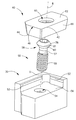
도 2는 도 1에 도시된 절삭 공구의 절삭부의 분해도,
도 3은 본 발명의 실시예에 따른 절삭 인서트의 평면도,
도 4는 도 3의 IV-IV 라인을 따라 취한 단면도,
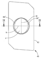
도 5는 절삭 인서트가 인서트 포켓에서 인서트 체결 위치에 있는 도 1에 도시된 절삭부의 평면도,
도 6은 도 5의 VI-VI 라인을 따라 취한 단면도,
도 7은 상승된 체결 부재를 도시하는 도 6에 도시된 것과 유사한 단면도,
도 8은 상승 위치의 절삭 인서트를 도시하는 도 7에 도시된 것과 유사한 단면도,
도 9는 개시 회전 위치의 절삭 인서트를 도시하는 도 8에 도시된 것과 유사한 단면도,
도 10은 중간 회전 위치의 절삭 인서트를 도시하는 도 6에 도시된 것과 유사한 단면도,
도 11은 도 12의 XI-XI 라인을 따라 취한 단면도, 또는 등가적으로 체결 부재의 헤드가 절삭 인서트 보어를 통과하도록 허용하는 인서트 제거 위치의 절삭 인서트를 도시하는 도 5에 도시된 것과 유사한 단면도,
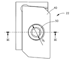
도 12는 도 11의 E 방향으로 지시된 절삭 인서트의 상면에서 취한 도 1에 도시된 절삭 공구의 절삭부의 도면,
도 13은 본 발명의 제2 실시예에 따른 절삭 인서트의 평면도,
도 14는 도 13의 XIV-XIV 라인을 따라 취한 단면도,
도 15는 본 발명의 제3 실시예에 따른 절삭 인서트의 평면도,
도 16은 도 15의 XVI-XVI 라인을 따라 취한 단면도,
도 17은 본 발명의 제4 실시예에 따른 절삭 인서트의 평면도,
도 18은 도 17의 XVIII-XVIII 라인을 따라 취한 단면도,
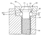
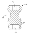
도 19는 본 발명의 몇몇 실시예에 따른 체결 부재의 측단면도이다.
도시의 단순화 및 명확화를 위해 도면에 도시된 요소들이 반드시 정확하거나 실척으로 도시되지 않았음을 이해할 것이다. 예를 들어, 요소들의 일부의 치수는 명확성을 위해 다른 요소들에 비해 과장될 수 있으며, 몇몇 물리적 요소들이 하나의 기능 블록 또는 요소에 포함될 수 있다. 또한, 적절하다고 여겨지는 경우, 도면에서 대응하거나 동일한 요소들을 지시하기 위해 도면부호가 반복될 수 있다.In order to better understand the present invention and to show how the invention is practiced, reference will now be made to the accompanying drawings.
1 is a perspective view of a cutting tool according to a first embodiment of the present invention,
2 is an exploded view of a cutting part of the cutting tool shown in FIG.
3 is a plan view of a cutting insert according to an embodiment of the present invention,
4 is a cross-sectional view taken along the line IV-IV of FIG.
5 is a plan view of the cutting portion shown in FIG. 1 with the cutting insert in the insert fastening position in the insert pocket, FIG.
FIG. 6 is a cross-sectional view taken along the line VI-VI of FIG. 5;
FIG. 7 is a cross sectional view similar to that shown in FIG. 6 showing a raised fastening member; FIG.
8 is a sectional view similar to that shown in FIG. 7 showing the cutting insert in the raised position, FIG.
9 is a cross-sectional view similar to that shown in FIG. 8 showing the cutting insert in the starting rotational position, FIG.
10 is a cross-sectional view similar to that shown in FIG. 6 showing the cutting insert in an intermediate rotational position;
FIG. 11 is a cross sectional view taken along the line XI-XI of FIG. 12, or a cross sectional view similar to that shown in FIG. 5 showing the cutting insert in an insert removal position that allows the head of the fastening member to pass through the cutting insert bore;
12 is a view of the cutting part of the cutting tool shown in FIG. 1 taken from the upper surface of the cutting insert indicated in the E direction of FIG.
13 is a plan view of a cutting insert according to a second embodiment of the present invention,
14 is a cross-sectional view taken along the line XIV-XIV of FIG. 13;
15 is a plan view of a cutting insert according to a third embodiment of the present invention,
16 is a cross-sectional view taken along the line XVI-XVI of FIG. 15;
17 is a plan view of a cutting insert according to a fourth embodiment of the present invention,
FIG. 18 is a cross-sectional view taken along the line XVIII-XVIII of FIG. 17;
19 is a side cross-sectional view of a fastening member in accordance with some embodiments of the present invention.
It is to be understood that the elements shown in the figures are not necessarily drawn to scale or clarity for simplicity and clarity of illustration. For example, the dimensions of some of the elements may be exaggerated relative to other elements for clarity, and some physical elements may be included in one functional block or element. Also, where considered appropriate, reference numerals may be repeated to indicate corresponding or identical elements in the figures.
이하의 설명에서, 본 발명의 다양한 양태가 설명될 것이다. 설명의 목적으로, 본 발명의 완전한 이해를 제공하기 위해 구체적인 구성 및 상세가 제공된다. 그러나 본 발명이 여기에 제공된 구체적인 상세 없이도 실시될 수 있음은 본 기술분야의 통상의 기술자에게 또한 자명할 것이다. 또한, 잘 알려진 특징들은 본 발명을 모호하게 하지 않도록 생략되거나 단순화될 수 있다.In the following description, various aspects of the invention will be described. For purposes of explanation, specific configurations and details are provided to provide a thorough understanding of the present invention. However, it will also be apparent to one skilled in the art that the present invention may be practiced without the specific details provided herein. In addition, well-known features may be omitted or simplified in order not to obscure the present invention.
전제적인 도면, 특히 본 발명의 실시예에 따른 5개의 절삭부(20)를 갖는 절삭 공구(10)의 사시도를 도시하는 도 1을 참조한다. 각 절삭부(20)는 체결 부재(50)에 의해 절삭 인서트(40)가 그 안에서 해제가능하게 고정되어 있는 인서트 포켓(30)을 포함하는 절삭 인서트 조립체(22)를 갖는다. 절삭부(20)의 개수는 5개로 제한되지 않으며, 절삭 인서트(40)의 형상은 임의의 특정 형상으로 제한되지 않는다.Reference is made to FIG. 1, which shows a perspective view of a
이제, 절삭 인서트 조립체(22)의 분해도를 도시하는 도 2를 참조한다. 인서트 포켓(30)은 인접한 제1 맞닿음 벽(52) 및 제2 맞닿음 벽(53), 제1 맞닿음 벽(52) 및 제2 맞닿음 벽(53)이 연장하는 포켓 기부(56)의 포켓 보어(54)를 갖는다. 몇몇 실시예에 따르면, 포켓 보어(54)는 나사가공될 수 있다. 절삭 인서트(40)는 절삭 인서트 보어(60), 제1 표면(62), 대향 제2 표면(64), 및 그 사이에서 연장하는 주연 표면(66)을 갖는다. 절삭 인서트 보어(60)는 제1 표면(62)과 제2 표면(64) 사이에서 연장한다. 제1 표면(62) 및 제2 표면(64)은 각각 제1 주연 모서리(42) 및 제2 주연 모서리(44)에서 주연 표면(66)과 만나며, 제1 주연 모서리(42)와 제2 주연 모서리(44) 중 적어도 하나의 적어도 일부가 절삭날(46)을 형성한다. 주연 표면(66)의 일부는 제1 맞닿음 벽(52) 및 제2 맞닿음 벽(53) 중 하나 또는 양자 모두와 맞닿을 수 있다.Reference is now made to FIG. 2, which shows an exploded view of the cutting
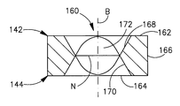
이제 도 3 및 도 4를 참조한다. 절삭 인서트 보어(60)는 제1 보어부(68), 제2 보어부(70), 및 제1 보어부(68)와 제2 보어부(70) 사이에 위치된 제3 보어부(72) 또는 중간 보어부를 갖는다. 제1 보어부(68) 및 제2 보어부(70)는 제3 보어부(72)와 연결된다. 제1 보어부(68)는 제1 표면(62)에 인접한 제1 보어 비맞닿음 표면(69') 및 제1 보어 비맞닿음 표면(69')으로부터 제2 표면(64)을 향해 내측 및 하방으로 연장하는 제1 보어 맞닿음 표면(69")을 갖는다. 제3 보어부(72)는 보어 축(B)에 수직이고 보어(60)가 비원형 단면을 갖는 보어 평면(P)을 포함한다. 몇몇 실시예에서, 보어 평면(P)은 보어 축(B)에 수직인 주 중심선(M) 및 보어 축(B)에 수직인 부 중심선(N)에 의해 규정된다. 주 중심선(M) 및 부 중심선(N)은 서로 수직이며, 보어 축(B)에 수직으로 취한 제3 보어부(72)의 단면의 주 보어 치수(DM) 및 부 보어 치수(DN)를 각각 규정한다. 제1 보어 맞닿음 표면(69")은 주 중심선(M)에 대해 대칭이며, 이러한 대칭성은 절삭 인서트(40)의 본체에 가해지는 토크와 같은 원치 않는 효과가 발생하지 않도록 하는데 중요하다.Reference is now made to FIGS. 3 and 4. The cutting insert bore 60 has a
제3 보어부(72)의 비원형 단면은 보어 평면(P)에 위치될 수 있고, 몇몇 실시예에 따르면 타원 형상을 가질 수 있다. 보어 축(B)에 수직으로 취한 제1 보어부(68) 및 제2 보어부(70)의 단면은 타원 형상을 갖지 않는다. 본 발명의 몇몇 실시예에 따르면, 타원이라는 용어는 도형의 중심에서 직교하는 2개의 수직축을 갖는 볼록한 형상의 폐곡선으로 형성된 도형을 의미한다. 이 도형은 축들 중 어느 한 축을 따르는 것이 다른 축을 따르는 것보다 더 넓고, 두 축을 각각 따라서 중심으로부터 외측으로 이동하는 동안 폭이 감소한다. 몇몇 실시예에 따르면, 제3 보어부(72)의 타원 단면(oval cross section)은 타원형(elliptical)일 수 있다. 보어 축(B)에 수직으로 취한 제3 보어부(72)의 단면은 보어 축(B)에 수직으로 취한 절삭 인서트 보어(60)의 임의의 다른 단면보다 작다.The non-circular cross section of the
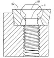
이제, 도 5 내지 도 8을 참조한다. 절삭 인서트(40)는 체결 부재(50)에 의해 인서트 포켓(30)에 고정된다. 체결 부재(50)는 체결 부재 헤드(58), 체결 부재 넥(57), 수나사 스레드 또는 임의의 다른 적절한 결합 수단을 가질 수 있는 체결 부재 결합부(59), 및 상하 방향을 규정하는 체결 부재 축(S)을 갖는다. 체결 부재 넥(57)은 체결 부재 결합부(59)와 체결 부재 헤드(58) 사이를 연결한다. 체결 부재 헤드(58)는 주연 표면(79) 및 체결 부재 헤드 직경(DS)을 가지며, DN<DS<DM이다. 체결 부재 헤드(58)는 체결 부재 헤드 주연 표면(79)상에 위치된 체결 부재 헤드 하부(80) 및 체결 부재 헤드 상부(78)를 갖는다. 몇몇 실시예에 따르면, 체결 부재 헤드(58)는 체결 부재 축(S)을 따라서 볼 때 체결 부재 헤드(58)가 원형 윤곽을 갖도록 체결 부재 축(S)을 중심으로 회전 대칭이다. 몇몇 실시예에 따르면, 체결 부재 헤드 상부(78) 및 체결 부재 헤드 하부(80)는 상호 연결부(81)로부터 연장한다. 몇몇 실시예에 따르면, 연결부(81)는 체결 부재 축(S)을 따라서 볼 때 체결 부재 헤드(58)의 원형 윤곽이 연결부(81)의 윤곽이 되도록 체결 부재 헤드(58)의 가장 넓은 부분이다.Reference is now made to FIGS. 5 to 8. The cutting
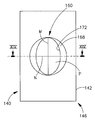
도 6에 도시된 바와 같이, 절삭 인서트(40)가 인서트 포켓(30)에 고정될 때, 즉 인서트 체결 위치에서, 체결 부재 헤드(58)는 절삭 인서트 보어(60)에 위치되고, 이때 체결 부재 헤드 하부(80)는 제1 보어 맞닿음 표면(69")과 결합한다. 이 위치에서, 체결 부재 헤드 하부(80)와 제1 보어 맞닿음 표면(69") 사이에서 큰 맞닿음 영역이 형성되고, 따라서 체결 부재가 조여질 때는 포켓 기부(56)를 향해 주로 하방으로 큰 커플링 힘이 생성된다. 체결 부재 결합부(59)는 완전히 커플링된 위치에서 체결 부재 결합부가 커플링되는 포켓 보어(54)에 수용된다. 몇몇 실시예에 따르면, 체결 부재 결합부(59)는 수나사 스레드를 가질 수 있고, 포켓 보어(54)는 암나사 스레드를 가질 수 있으며, 체결 부재 결합부(59)는 포켓 보어(54)에 나사식으로 수용될 수 있다. 도 5에서 볼 수 있으며, 도 6으로부터 이해할 수 있듯이, 절삭 인서트(40)가 인서트 포켓(30)에 고정될 때, 즉 인서트 체결 위치에서, 절삭 인서트(40)의 상면에서, 체결 부재 헤드(58)는 절삭 인서트 보어(60)를 통과할 수 없는 큰 윤곽을 갖고, 그로 인해 체결 부재 헤드(58)가 절삭 인서트 보어(60)를 통과하는 것을 허용하지 않는다.As shown in FIG. 6, when the cutting
체결 부재(50)에 대해, 중간 중심선(C)은 체결 부재(50)와 부 중심선(N)의 교차에 의해 규정된다. 중간 중심선(C)은 (도 6 및 도 8 내지 도 12에 도시된 바와 같이) 2개의 교차 종료 지점(P1, P2)을 갖는다. 중간 중심선(C)은 항상 부 보어 치수(DN)보다 작은 중간 중심선 치수(DC)를 갖는다. 중간 중심선(C)은 체결 부재 헤드(58)와 부 중심선(N)의 교차에 의해 규정되기 때문에, 부 중심선(N) 상에 위치된다. 도 10 및 도 11에서는 중간 중심선(C)과 부 중심선(N)이 동일시(coextensive)되어 있지만, 실제로는 이렇지 않고, 도 10 및 도 11에 도시된 위치에서는 중간 중심선(C)이 도 6에 도시된 부 중심선(N)보다 약간 짧다는 것을 도시할 수 있을 정도로 도면에서 선(line)의 해상도가 크지 못하기 때문에 이렇게 보일 뿐이다.For the
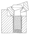
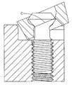
절삭 인서트(40)를 교체 또는 인덱싱하기 위해서는 이하 도시될 바와 같이, 체결 부재(50)를 포켓 보어(54)로부터 완전히 제거할 필요가 없다. 절삭 인서트(40)를 교체 또는 인덱싱하기 위해서는 체결 부재 결합부(59)가 부분적으로 커플링된 위치(도 7 내지 도 11 참조)에서 포켓 보어(54)에 커플링되어 남아있도록 체결 부재(50)를 포켓 보어(54)로부터 부분적으로 제거하는 것으로 충분하다. 체결 부재 헤드(58)는 체결 부재 결합부(59)가 완전히 커플링된 위치에 있을 때(도 6 참조)보다 체결 부재 결합부(59)가 부분적으로 커플링된 위치에 있을 때 포켓 기부(56)로부터 더욱 제거된다. 체결 부재 결합부(59)가 부분적으로 커플링된 위치에 있을 때, 절삭 인서트(40)는 포켓 기부(56)로부터 상승 위치(도 8 참조)로 상승될 수 있다. 절삭 인서트(40)는 상승 위치에서 도 9에 도시된 바와 같이 개시 회전 위치로부터 주 중심선(M)을 중심으로 회전될 수 있고, 동시에 절삭 인서트가 인서트 제거 위치(도 11 참조)에 도달할 때까지 도 10에 도시된 바와 같은 중간 회전 위치로 주 중심선(M)에 수직하게 절삭 인서트를 이동시키며, 인서트 제거 위치에서는 도 12에 도시된 바와 같이 절삭 인서트(40)의 상면에서 체결 부재 헤드(58)의 윤곽이 절삭 인서트 보어(60)를 통과하기에 충분히 작으며, 그로 인해 체결 부재 헤드(58)가 절삭 인서트 보어(60)를 통과하는 것이 허용된다. 인서트 제거 위치에서, 절삭 인서트(40)는 체결 부재 헤드(58)로부터 절삭 인서트를 상승시킴으로써 인서트 포켓(30)으로부터 제거될 수 있다. 체결 부재 결합부(59)가 포켓 보어(54)에 클램핑되어 있는 동안 교체 절삭 인서트를 설치하기 위해서는 전술한 작업이 역순으로 실시된다.In order to replace or index the cutting
전술한 절삭 인서트(40)의 회전 동안의 중간 중심선 치수(DC)의 변화는 (도 9 내지 도 12에 도시된 바와 같이) 체결 부재 헤드(50)가 어떻게 내부에서 점진적으로 끼워지고 종국적으로는 제3 보어부(72)의 타원 형상의 단면을 통과하는지를 설명한다.The change in the intermediate centerline dimension D C during the rotation of the cutting
다른 실시예에 따르면, 절삭 인서트 보어(160)를 갖는 절삭 인서트(140)가 도 13 및 도 14에 도시된다. 절삭 인서트(140)는 제1 주연 모서리(142) 및 제2 주연 모서리(144)를 각각 가지며, 제1 주연 모서리(142) 및 제2 주연 모서리(144) 중 적어도 하나의 적어도 일부는 절삭날(146)을 형성한다. 절삭 인서트 보어(160)는 제1 보어부(168), 제2 보어부(170), 및 제3 보어부(172)를 포함한다. 제1 보어부는 제1 표면(162)으로 개방되고, 제2 보어부(170)는 제2 표면(164)으로 개방되며, 제3 보어부(172)는 대체로 제1 보어부(168)와 제2 보어부(170) 사이에 위치된다. 절삭 인서트 보어(160)의 일부 구역에서, 제1 보어부(168) 및 제2 보어부(170)는 접촉한다. 제3 보어부(172)는 절삭 인서트(140)의 주연 표면(166)과 동일한 높이를 갖는 몇몇 세그먼트를 가질 수 있는데, 이 경우 제3 보어부는 적어도 제1 표면(262)으로 부분적으로 개방된다. 또한, 제1 보어부(168) 및 제2 보어부(170)가 동일하다면, 절삭 인서트(140)는 리버서블(reversible) 절삭 인서트이다.According to another embodiment, the cutting
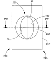
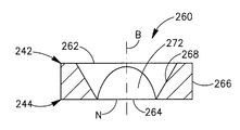
도 15 및 도 16에 도시된 다른 실시예에 따르면, 절삭 인서트(240)는 제1 주연 모서리(242) 및 제2 주연 모서리(244)를 각각 가지며, 제1 주연 모서리(242) 및 제2 주연 모서리(244) 중 적어도 하나의 적어도 일부는 절삭날(246)을 형성한다. 절삭 인서트(240)는 단지 2개의 보어부를 구비한 절삭 인서트 보어(260)를 가지며, 절삭 인서트(240)의 제1 보어부(268)는 제1 표면(262)으로 개방되고, 제2 보어부(272)는 제2 표면(264)으로 개방된다. 제2 보어부(272)는 절삭 인서트(240)의 주연 표면(266)과 동일한 높이를 갖는 몇몇 세그먼트를 또한 가질 수 있는데, 이 경우 제2 보어부(272)는 제1 표면(262)으로 부분적으로 개방된다.According to another embodiment shown in FIGS. 15 and 16, the cutting
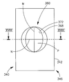
도 17 및 도 18에 도시된 또 다른 실시예에 따르면, 절삭 인서트(340)는 주연 표면, 제1 주연 모서리(342) 및 제2 주연 모서리(344)를 각각 가지며, 제1 주연 모서리(342) 및 제2 주연 모서리(344) 중 적어도 하나의 적어도 일부는 절삭날(346)을 형성한다. 절삭 인서트(340)는 제1 표면(362)으로 개방되는 원통형 제1 보어부(368) 및 제2 표면(364)으로 개방되는 원통형 제2 보어부(370)를 갖는 절삭 인서트 보어(360)를 갖는다. 원통형 제1 보어부(368) 및 원통형 제2 보어부(370)가 동일하다면, 절삭 인서트(340)는 리버서블 절삭 인서트이다.According to another embodiment shown in FIGS. 17 and 18, the cutting
도 19에 도시된 몇몇 실시예에 따르면, 체결 부재(150)는 체결 부재(150)에 토크를 인가하기 위해 체결 부재 헤드(158)내의 제1 리세스(151) 이외에 체결 부재(150)에 토크를 인가하기 위해 커플링부(159)내의 제2 리세스(155)를 가질 수 있다. 이러한 배열은 체결 부재 헤드(158)로의 접근이 곤란하거나 불가능할 때 특히 유용하다. 또한, 본 발명에 따르면, 절삭 인서트를 제거 및 교체하기 위해 체결 부재(150)가 제거될 필요 없이 단지 느슨해지기 때문에, 커플링부(159)는 보어를 통해 절삭 인서트를 통과할 필요가 없다. 그 결과, 커플링부(159)는 체결 부재 헤드(158)의 직경과 동일한 직경을 가질 수 있다. 이는 제2 리세스(155)가 제1 리세스(151)와 동일한 치수를 가질 수 있고, 그로 인해 제1 리세스(151) 및 제2 리세스(155) 양자 모두에 대해 단일의 토크 인가 부재를 사용할 수 있는 경우이다.According to some embodiments shown in FIG. 19, the
본 발명의 실시예에 따르면, 절삭 인서트(140, 340) 또는 절삭 인서트 보어(160, 360), 또는 양자 모두는 주 중심선(M) 및 부 중심선(N)에 의해 규정된 보어 평면(P)에 대해 반사 대칭일 수 있다.According to an embodiment of the invention, the cutting inserts 140, 340 or the cutting insert bores 160, 360, or both, are in the bore plane P defined by the main center line M and the sub center line N. It can be reflective symmetry.
하나 이상의 구체적인 실시예를 참조하여 본 발명이 설명되었지만, 이러한 설명은 전체로서 설명을 위한 것이며 본 발명을 도시된 실시예로 제한하여 해석하도록 하기 위함이 아니다. 본 기술분야의 통상의 기술자는 본 발명의 범위 내에서 본원에 구체적으로 도시되지 않은 다양한 개조를 할 수 있는 것으로 이해되어야 한다.Although the present invention has been described with reference to one or more specific embodiments, these descriptions are for illustrative purposes as a whole and are not intended to limit the invention to the illustrated embodiments. It should be understood that those skilled in the art can make various modifications which are not specifically shown herein within the scope of the present invention.
Claims (9)
제1 표면(62, 162, 362), 제2 표면(64, 164, 364), 및 그 사이에서 연장하는 주연 표면(66, 166, 366)과,
제1 표면과 제2 표면 사이에서 연장하고 보어 축(B)을 갖는 절삭 인서트 보어(60, 160, 360)를 포함하며,
제1 표면(62, 162, 362) 및 제2 표면(64, 164, 364)은 각각 제1 주연 모서리(42, 142, 342) 및 제2 주연 모서리(44, 144, 344)에서 주연 표면(66, 166, 366)과 만나고, 제1 주연 모서리(42, 142, 342) 및 제2 주연 모서리(44, 144, 344) 중 적어도 하나의 적어도 일부가 절삭날(46, 146, 346)을 형성하며,
절삭 인서트 보어는
제1 표면(62, 162, 362)으로 개방되는 제1 보어부(68, 168, 368)와,
제2 표면(64, 164, 364)으로 개방되는 제2 보어부(70, 170, 370)와,
제1 보어부(68, 168, 368)와 제2 보어부(70, 170, 370) 사이에 위치되어 이들을 각각 병합하는 제3 보어부(72, 172, 372)로서, 보어 축(B)에 수직으로 취한 제3 보어부(72, 172, 372)의 단면의 주 치수(DM) 및 부 치수(DN)를 각각 규정하는 보어 축(B)에 수직인 주 중심선(M) 및 보어 축(B)에 수직인 부 중심선(N)을 갖는 제3 보어부(72, 172, 372)를 포함하고,
단면은 타원 형상을 갖는
절삭 인서트(40, 140, 340).Cutting inserts 40, 140, 340,
First surfaces 62, 162, 362, second surfaces 64, 164, 364, and peripheral surfaces 66, 166, 366 extending therebetween,
A cutting insert bore 60, 160, 360 extending between the first and second surfaces and having a bore axis B,
The first surface 62, 162, 362 and the second surface 64, 164, 364 respectively have a peripheral surface (at the first peripheral edge 42, 142, 342 and the second peripheral edge 44, 144, 344). 66, 166, 366 and at least a portion of at least one of the first peripheral edges 42, 142, 342 and the second peripheral edges 44, 144, 344 form cutting edges 46, 146, 346. ,
Cutting insert bore
First bore portions 68, 168, 368 that open to first surfaces 62, 162, 362, and
Second bore portions 70, 170, 370 opening to second surfaces 64, 164, 364, and
Third bore portions 72, 172, 372, which are located between the first bore portions 68, 168, 368 and the second bore portions 70, 170, 370 and merge them, respectively, on the bore axis B. Main center line M and the bore axis perpendicular to the bore axis B defining the major dimension D M and minor dimension D N of the cross section of the third bore portions 72, 172, 372 taken vertically, respectively. Third bore portions 72, 172, 372 having a minor centerline N perpendicular to (B),
The cross section has an elliptic shape
Cutting inserts 40, 140, 340.
보어 평면(P)은 주 중심선(M) 및 부 중심선(N)에 의해 규정되고,
절삭 인서트(140, 340)는 보어 평면(P)에 대해 반사 대칭인
절삭 인서트(140, 340).The method of claim 1,
The bore plane P is defined by the main center line M and the sub center line N,
The cutting inserts 140, 340 are reflective symmetric about the bore plane P
Cutting inserts 140, 340.
보어 평면(P)은 주 중심선(M) 및 부 중심선(N)에 의해 규정되고,
절삭 인서트 보어(160, 360)는 보어 평면(P)에 대해 반사 대칭인
절삭 인서트(140, 340).The method of claim 1,
The bore plane P is defined by the main center line M and the sub center line N,
The cutting insert bores 160, 360 are reflective symmetric about the bore plane P
Cutting inserts 140, 340.
절삭 인서트 보어(360)는 원통형 제1 보어부(368) 및 원통형 제2 보어부(370)를 갖는
절삭 인서트(340).The method of claim 1,
The cutting insert bore 360 has a cylindrical first bore portion 368 and a cylindrical second bore portion 370.
Cutting insert 340.
제1 표면(262), 제2 표면(264), 및 그 사이에서 연장하는 주연 표면(266)과,
제1 표면과 제2 표면 사이에서 연장하고 보어 축(B)을 갖는 절삭 인서트 보어(260)를 포함하며,
제1 표면(262) 및 제2 표면(264)은 각각 제1 주연 모서리(242) 및 제2 주연 모서리(244)에서 주연 표면(266)과 만나고, 제1 주연 모서리(242) 및 제2 주연 모서리(244) 중 적어도 하나의 적어도 일부가 절삭날(246)을 형성하며,
절삭 인서트 보어는
제1 표면(262)으로 개방되는 제1 보어부(268)와,
제2 표면(264)으로 개방되는 제2 보어부(272)로서, 보어 축(B)에 수직으로 취한 제2 보어부(272)의 단면의 주 치수(DM) 및 부 치수(DN)를 각각 규정하는 보어 축(B)에 수직인 주 중심선(M) 및 보어 축(B)에 수직인 부 중심선(N)을 갖는 제2 보어부(272)를 포함하고,
단면은 타원 형상을 갖는
절삭 인서트(240).Cutting insert 240,
A first surface 262, a second surface 264, and a peripheral surface 266 extending therebetween,
A cutting insert bore 260 extending between the first surface and the second surface and having a bore axis B,
The first surface 262 and the second surface 264 meet the peripheral surface 266 at the first peripheral edge 242 and the second peripheral edge 244, respectively, and the first peripheral edge 242 and the second peripheral edge At least a portion of at least one of the edges 244 forms the cutting edge 246,
Cutting insert bore
A first bore portion 268 opening to the first surface 262,
As the second bore portion 272 opening to the second surface 264, the major dimension D M and the minor dimension D N of the cross section of the second bore portion 272 taken perpendicular to the bore axis B. A second bore portion 272 having a main centerline M perpendicular to the bore axis B and a minor centerline N perpendicular to the bore axis B, respectively defining
The cross section has an elliptic shape
Cutting insert 240.
포켓 보어(54)를 포함하는 포켓 기부(56)를 갖는 인서트 포켓(30)과,
체결 부재 헤드(58) 및 포켓 보어(54)에 수용되는 체결 부재 결합부(59)를 갖는 체결 부재(50)와,
제1항 또는 제2항에 따른 절삭 인서트(40, 140, 240, 340)로서, 체결 부재 헤드 하부(80)가 제1 보어 맞닿음 표면(69")과 결합하는 인서트 체결 위치와 인서트 제거 위치 사이에서 이동가능한 절삭 인서트(40, 140, 240, 340)를 포함하며,
인서트 체결 위치에서는 절삭 인서트(40, 140, 240, 340)의 상면에서 체결 부재 헤드(58)가 절삭 인서트 보어(60, 160, 260, 360)를 통과할 수 없는 큰 윤곽을 가지며,
인서트 제거 위치에서는 절삭 인서트(40, 140, 240, 340)의 상면에서 체결 부재 헤드(58)가 절삭 인서트 보어(60, 160, 260, 360)를 통과할 수 있는 작은 윤곽을 갖는
절삭 인서트 조립체(22).Cutting insert assembly 22,
An insert pocket 30 having a pocket base 56 comprising a pocket bore 54,
A fastening member 50 having a fastening member engaging portion 59 received in the fastening member head 58 and the pocket bore 54;
Cutting inserts 40, 140, 240, 340 according to claim 1, wherein the insert fastening position and the insert removal position at which the fastening member head bottom 80 engages with the first bore abutment surface 69 ″. A cutting insert 40, 140, 240, 340 that is movable between
In the insert fastening position, the fastening member head 58 has a large contour at the top of the cutting inserts 40, 140, 240, 340 that cannot pass through the cutting insert bores 60, 160, 260, 360,
In the insert removal position, the fastening member head 58 at the top of the cutting insert 40, 140, 240, 340 has a small contour that can pass through the cutting insert bores 60, 160, 260, 360.
Cutting insert assembly 22.
체결 부재 결합부(159)는 체결 부재 헤드(158)의 직경과 동일한 직경을 갖는
절삭 인서트 조립체(22).The method of claim 6,
The fastening member coupling part 159 has a diameter equal to the diameter of the fastening member head 158.
Cutting insert assembly 22.
체결 부재 헤드(158)는 제1 리세스(151)를 갖고, 결합부(159)는 제1 리세스(151)와 동일한 치수를 갖는 제2 리세스(155)를 갖는
절삭 인서트 조립체(22).The method of claim 7, wherein
The fastening member head 158 has a first recess 151 and the engaging portion 159 has a second recess 155 having the same dimensions as the first recess 151.
Cutting insert assembly 22.
a) 체결 부재 결합부(59)가 부분적으로 체결된 위치에서 포켓 보어(54)에 체결되어 유지되도록 포켓 보어(54)로부터 체결 부재(50)를 부분적으로 제거하는 단계와,
b) 포켓 기부(56)로부터 상승 위치로 절삭 인서트(40, 140, 240, 340)를 상승시키는 단계와,
c) 개시 회전 위치로부터 주 중심선(M)을 중심으로 절삭 인서트(40, 140, 240, 340)를 회전시키고, 절삭 인서트의 상면에서 체결 부재 헤드(58)의 윤곽이 절삭 인서트 보어를 통과할 수 있는 작은 형상을 형성하는 인서트 제거 위치로 주 중심선(M)에 수직하게 절삭 인서트를 이동시키는, 절삭 인서트의 회전 및 이동 단계와,
d) 절삭 인서트를 체결 부재 헤드(58)로부터 상승시켜 절삭 인서트(40, 140, 240, 340)를 제거하는 단계를 포함하는
절삭 인서트 교체 또는 인덱싱 방법.Replacement of cutting inserts 40, 140, 240, 340 according to claim 1 or 2 fixed by fastening member 50 in insert pocket 30 of cutting insert assembly 22 of cutting tool 10. Or as an indexing method, wherein the insert pocket 30 has a pocket bore 54 and a pocket base 56, and the fastening member 50 has a fastening member head 58 and a fastening member engaging portion 59. Replacement or indexing method,
a) partially removing the fastening member 50 from the pocket bore 54 such that the fastening member engaging portion 59 remains engaged with the pocket bore 54 in a partially fastened position;
b) raising the cutting inserts 40, 140, 240, 340 from the pocket base 56 to the raised position,
c) the cutting inserts 40, 140, 240, 340 are rotated about the main center line M from the starting rotational position, and the contour of the fastening member head 58 can pass through the cutting insert bore on the upper surface of the cutting insert. Rotating and moving the cutting insert, moving the cutting insert perpendicular to the main center line M to the insert removal position forming a small shape which
d) lifting the cutting insert away from the fastening member head 58 to remove the cutting insert 40, 140, 240, 340.
Cutting insert replacement or indexing method.
Applications Claiming Priority (3)
| Application Number | Priority Date | Filing Date | Title |
|---|---|---|---|
| IL198376 | 2009-04-26 | ||
| IL198376A IL198376A (en) | 2009-04-26 | 2009-04-26 | Cutting insert and cutting insert assembly |
| PCT/IL2010/000263 WO2010125554A1 (en) | 2009-04-26 | 2010-03-28 | Cutting insert and cutting insert assembly |
Publications (1)
| Publication Number | Publication Date |
|---|---|
| KR20120013344A true KR20120013344A (en) | 2012-02-14 |
Family
ID=42113734
Family Applications (1)
| Application Number | Title | Priority Date | Filing Date |
|---|---|---|---|
| KR1020117025183A KR20120013344A (en) | 2009-04-26 | 2010-03-28 | Cutting insert and cutting insert assembly |
Country Status (14)
| Country | Link |
|---|---|
| US (1) | US8747031B2 (en) |
| EP (1) | EP2424699B1 (en) |
| JP (2) | JP5965836B2 (en) |
| KR (1) | KR20120013344A (en) |
| CN (1) | CN102438785B (en) |
| BR (1) | BRPI1013979B1 (en) |
| CA (1) | CA2758535C (en) |
| ES (1) | ES2780149T3 (en) |
| IL (1) | IL198376A (en) |
| PL (1) | PL2424699T3 (en) |
| PT (1) | PT2424699T (en) |
| RU (1) | RU2518835C2 (en) |
| TW (1) | TW201043360A (en) |
| WO (1) | WO2010125554A1 (en) |
Families Citing this family (14)
| Publication number | Priority date | Publication date | Assignee | Title |
|---|---|---|---|---|
| EP2401107B1 (en) | 2009-02-27 | 2018-01-03 | No Screw Ltd. | Cutting tool holder and cutting tool including such a cutting tool holder |
| CN103702788B (en) * | 2011-08-02 | 2016-11-16 | 伊斯卡有限公司 | Cutting element and for cutting tip being remained to clamping device thereon |
| CN202291575U (en) * | 2011-10-12 | 2012-07-04 | 益壮企业有限公司 | T-shaped milling cutter |
| CN102601439A (en) * | 2011-12-19 | 2012-07-25 | 株洲钻石切削刀具股份有限公司 | Milling cutter |
| US8746115B2 (en) * | 2012-01-09 | 2014-06-10 | Iscar, Ltd. | Cutting insert having hole orientation indicia and method for making thereof |
| KR101757033B1 (en) * | 2012-10-10 | 2017-07-11 | 이스카 엘티디. | Cutting insert, cutting body and clamping mechnism of a cutting tool assembly for chip removal |
| EP3041632B1 (en) | 2013-09-03 | 2023-06-07 | No Screw Ltd. | Mounting mechanism for a cutting insert, a cutting insert therefor and a cutting tool using said insert |
| US20160121406A1 (en) | 2014-10-29 | 2016-05-05 | Illinois Tool Works Inc. | Interchangeable cutting inserts and methods associated with the same |
| CN104400358B (en) * | 2014-11-24 | 2017-08-11 | 马鞍山市恒利达机械刀片有限公司 | The processing method that tool rest is combined in a kind of double millings of mechanical quick-replaceable type aluminium ingot |
| US9962774B2 (en) * | 2014-12-08 | 2018-05-08 | The Boeing Company | Cutting tool |
| JP2018504288A (en) | 2015-02-04 | 2018-02-15 | ノー スクリュー リミテッド | Cutting tool with cutting tool holder and cutting insert therefor |
| WO2016174663A1 (en) | 2015-04-30 | 2016-11-03 | No Screw Ltd. | Dynamic clamping mechanism |
| CN110997199B (en) * | 2017-08-18 | 2023-08-25 | 伊利诺斯工具制品有限公司 | Interchangeable cutting insert and pipe cutting assembly/machining apparatus including the same |
| BR112020010545B1 (en) * | 2017-11-30 | 2023-09-26 | Iscar Ltd | REPLACEABLE TURNING TOOL ADAPTER, AND, MODULAR TURNING TOOL |
Family Cites Families (22)
| Publication number | Priority date | Publication date | Assignee | Title |
|---|---|---|---|---|
| US3654682A (en) * | 1970-09-01 | 1972-04-11 | Edward H Newbould | Tool holder |
| US3740807A (en) * | 1972-02-25 | 1973-06-26 | Metal Cutting Tools Inc | Inserted blade cutting tool with locking pin |
| US3913197A (en) * | 1973-11-19 | 1975-10-21 | Heinz K Wolf | Positive lock insert |
| DE2906148A1 (en) * | 1979-02-17 | 1980-08-28 | Walter Gmbh Montanwerke | CUTTING TOOL WITH REPLACEMENT INSERT |
| US4397592A (en) * | 1980-11-10 | 1983-08-09 | Kennametal Inc. | Insert holder and method of holding |
| SU1255287A1 (en) * | 1985-04-03 | 1986-09-07 | Medvedev Mikhail D | Assembled cutting tool |
| SU1542700A1 (en) * | 1987-11-12 | 1990-02-15 | Краматорский Индустриальный Институт | Two-sided cutting bit |
| JPH02135115U (en) * | 1989-04-14 | 1990-11-09 | ||
| US5039259A (en) * | 1990-06-04 | 1991-08-13 | Duncan Thomas E | Diamond edge milling tool |
| SE9003705L (en) * | 1990-11-21 | 1992-05-22 | Seco Tools Ab | SKAERVERKTYG |
| SE505726C2 (en) | 1995-02-27 | 1997-10-06 | Sandvik Ab | Clamping device for cutting plates |
| JP2003165004A (en) * | 2001-11-29 | 2003-06-10 | Ngk Spark Plug Co Ltd | Turning tool |
| JP2004167635A (en) * | 2002-11-20 | 2004-06-17 | Mitsubishi Materials Corp | Mechanism for clamping throwaway chip, and throwaway tip used for the same |
| JP2004261937A (en) * | 2003-03-04 | 2004-09-24 | Kyocera Corp | Throw away type cutting tool |
| US7771142B2 (en) * | 2003-05-09 | 2010-08-10 | Kennametal Inc. | Cutting insert with elliptical cutting edge |
| JP4639862B2 (en) * | 2004-03-26 | 2011-02-23 | 三菱マテリアル株式会社 | Claw mechanism for throw-away tip |
| KR100625838B1 (en) * | 2004-11-16 | 2006-09-20 | 대구텍 주식회사 | Insert Tip |
| JP4639881B2 (en) * | 2005-03-24 | 2011-02-23 | 株式会社タンガロイ | Throw-away cutting tool |
| SE528710C2 (en) * | 2005-06-01 | 2007-01-30 | Sandvik Intellectual Property | Indexable cutter with the coupling means arranged on a release surface |
| SE530374C2 (en) * | 2006-05-23 | 2008-05-20 | Pramet Tools Sro | Cutting insert and cutting tool where the clamping surface of the clamping hole is in the form of an elliptical cone |
| US7959383B2 (en) * | 2006-09-06 | 2011-06-14 | Taegutec Ltd. | Cutting insert and cutting tool therewith |
| ES2636997T3 (en) * | 2007-04-26 | 2017-10-10 | Taegu Tec India P.Ltd. | Strawberry cutting insert |
-
2009
- 2009-04-26 IL IL198376A patent/IL198376A/en active IP Right Grant
-
2010
- 2010-03-25 TW TW099108944A patent/TW201043360A/en unknown
- 2010-03-28 BR BRPI1013979-6A patent/BRPI1013979B1/en active IP Right Grant
- 2010-03-28 PL PL10720825T patent/PL2424699T3/en unknown
- 2010-03-28 JP JP2012506642A patent/JP5965836B2/en active Active
- 2010-03-28 EP EP10720825.8A patent/EP2424699B1/en active Active
- 2010-03-28 RU RU2011148103/02A patent/RU2518835C2/en active
- 2010-03-28 CN CN201080018247.6A patent/CN102438785B/en active Active
- 2010-03-28 WO PCT/IL2010/000263 patent/WO2010125554A1/en active Application Filing
- 2010-03-28 KR KR1020117025183A patent/KR20120013344A/en not_active Application Discontinuation
- 2010-03-28 PT PT107208258T patent/PT2424699T/en unknown
- 2010-03-28 CA CA2758535A patent/CA2758535C/en active Active
- 2010-03-28 ES ES10720825T patent/ES2780149T3/en active Active
- 2010-04-22 US US12/765,604 patent/US8747031B2/en active Active
-
2014
- 2014-12-12 JP JP2014252235A patent/JP2015062993A/en active Pending
Also Published As
| Publication number | Publication date |
|---|---|
| JP2012524666A (en) | 2012-10-18 |
| US8747031B2 (en) | 2014-06-10 |
| CA2758535A1 (en) | 2010-11-04 |
| CN102438785B (en) | 2014-06-11 |
| IL198376A (en) | 2013-04-30 |
| WO2010125554A1 (en) | 2010-11-04 |
| CA2758535C (en) | 2016-04-12 |
| JP2015062993A (en) | 2015-04-09 |
| IL198376A0 (en) | 2010-02-17 |
| BRPI1013979B1 (en) | 2020-08-11 |
| RU2518835C2 (en) | 2014-06-10 |
| PT2424699T (en) | 2020-05-14 |
| US20100272522A1 (en) | 2010-10-28 |
| TW201043360A (en) | 2010-12-16 |
| RU2011148103A (en) | 2013-06-10 |
| CN102438785A (en) | 2012-05-02 |
| JP5965836B2 (en) | 2016-08-10 |
| BRPI1013979A2 (en) | 2016-04-05 |
| EP2424699B1 (en) | 2020-03-25 |
| ES2780149T3 (en) | 2020-08-24 |
| EP2424699A1 (en) | 2012-03-07 |
| PL2424699T3 (en) | 2020-07-13 |
Similar Documents
| Publication | Publication Date | Title |
|---|---|---|
| KR20120013344A (en) | Cutting insert and cutting insert assembly | |
| KR101674697B1 (en) | Cutting insert with recessed insert supporting surface, and cutting tool | |
| EP1736263B1 (en) | Clamping structure for throwaway chip | |
| US9649701B2 (en) | Cutting insert and indexable insert-type cutting tool | |
| CN1761547B (en) | A milling tool with cooperating projections and recesses between the cutting insert and the holder | |
| KR101323558B1 (en) | Insert with a mounting hole and toolholder including a cutting insert | |
| RU2568227C2 (en) | Cutting plate with grooved surface forming multiple bearing surfaces | |
| US7347650B2 (en) | Cutting tool with locking pin | |
| BR112015018165B1 (en) | INDEXABLE CUTTING INSERT AND CUTTING TOOL | |
| BRPI0809071A2 (en) | CUTTING INSERT AND CUTTING TOOL | |
| CZ301486B6 (en) | Cutting insert with diametrically opposite corner cutting teeth on different sides of the insert and tool provided with such an insert | |
| US9700945B2 (en) | Cutting tool | |
| MXPA04002566A (en) | Cutter insert and milling tool. | |
| WO2016147493A1 (en) | Cutting insert, cutting insert group, and blade tip replacement cutting tool | |
| KR20110005303A (en) | Mechanism for temporarily holding tip, and throw-away cutting tool provided with the mechanism | |
| CN104708037A (en) | Cutting tool with replaceable abutment members and toolholder and cutting insert therefor | |
| BR112014003789B1 (en) | cutting insert and cutting tool set | |
| WO2018042957A1 (en) | Cutting insert | |
| KR20110125223A (en) | Cutting tool having an adjustment mechanism | |
| KR20120112578A (en) | Cutting edge replacement type groove forming tool and end face groove forming method | |
| KR101444470B1 (en) | Cutting tool | |
| JP6052712B2 (en) | Cutting tools | |
| TW201924815A (en) | Double-sided cutting insert having orientation-assisting clamping recesses and cutting tool | |
| JP6964092B2 (en) | Metal cutting grooving insert for face grooving | |
| RU2778708C2 (en) | Indexable cutting insert of triangular shape with deepened side surfaces, and rotating cutting tool |
Legal Events
| Date | Code | Title | Description |
|---|---|---|---|
| A201 | Request for examination | ||
| E902 | Notification of reason for refusal | ||
| E601 | Decision to refuse application |