EP2423872A1 - Ultrasonic image processing apparatus - Google Patents
Ultrasonic image processing apparatus Download PDFInfo
- Publication number
- EP2423872A1 EP2423872A1 EP20110006351 EP11006351A EP2423872A1 EP 2423872 A1 EP2423872 A1 EP 2423872A1 EP 20110006351 EP20110006351 EP 20110006351 EP 11006351 A EP11006351 A EP 11006351A EP 2423872 A1 EP2423872 A1 EP 2423872A1
- Authority
- EP
- European Patent Office
- Prior art keywords
- image
- processing
- pixel
- interpolation processing
- original image
- Prior art date
- Legal status (The legal status is an assumption and is not a legal conclusion. Google has not performed a legal analysis and makes no representation as to the accuracy of the status listed.)
- Withdrawn
Links
Images


Classifications
-
- G—PHYSICS
- G06—COMPUTING OR CALCULATING; COUNTING
- G06T—IMAGE DATA PROCESSING OR GENERATION, IN GENERAL
- G06T3/00—Geometric image transformations in the plane of the image
- G06T3/40—Scaling of whole images or parts thereof, e.g. expanding or contracting
- G06T3/403—Edge-driven scaling; Edge-based scaling
-
- A—HUMAN NECESSITIES
- A61—MEDICAL OR VETERINARY SCIENCE; HYGIENE
- A61B—DIAGNOSIS; SURGERY; IDENTIFICATION
- A61B8/00—Diagnosis using ultrasonic, sonic or infrasonic waves
- A61B8/48—Diagnostic techniques
- A61B8/483—Diagnostic techniques involving the acquisition of a 3D volume of data
-
- A—HUMAN NECESSITIES
- A61—MEDICAL OR VETERINARY SCIENCE; HYGIENE
- A61B—DIAGNOSIS; SURGERY; IDENTIFICATION
- A61B8/00—Diagnosis using ultrasonic, sonic or infrasonic waves
-
- A—HUMAN NECESSITIES
- A61—MEDICAL OR VETERINARY SCIENCE; HYGIENE
- A61B—DIAGNOSIS; SURGERY; IDENTIFICATION
- A61B8/00—Diagnosis using ultrasonic, sonic or infrasonic waves
- A61B8/46—Ultrasonic, sonic or infrasonic diagnostic devices with special arrangements for interfacing with the operator or the patient
- A61B8/461—Displaying means of special interest
- A61B8/463—Displaying means of special interest characterised by displaying multiple images or images and diagnostic data on one display
Definitions
- the present invention relates to an ultrasonic image processing apparatus, and more particularly to technology for enhancing the image quality of a three-dimensional ultrasonic image.
- An ultrasonic image processing apparatus is an apparatus which forms an ultrasonic image based on data acquired by transmission and reception of ultrasound or which processes such an ultrasonic image, and is configured as an ultrasonic diagnosis apparatus or an information processing apparatus.
- an information processing apparatus is a computer which processes data transmitted from an ultrasonic diagnosis apparatus, for example.
- an ultrasonic image to be formed or to be processed includes a two-dimensional ultrasonic image, a three-dimensional ultrasonic image, or the like.
- volume rendering image By applying a volume rendering method to volume data (a set of echo data) acquired from a three-dimensional space within a living organism (a living body), a three-dimensional ultrasonic image (a volume rendering image) is formed. More specifically, first, a plurality of rays (virtual lines of sight, which correspond to an operation path) extending from a point of view are set with respect to the volume data, and then a predetermined operation is executed in a repeated manner sequentially for sample points existing on each of the rays, thereby obtaining a pixel value for each ray. Finally, a three-dimensional image is formed as a set of a plurality of pixel values corresponding to the plurality of rays. (See JP 10-33538 A , for example.)
- I a pixel value (a brightness value)
- e(i) represents an echo intensity (an echo value) on a sample point on a ray
- o(e(i)) represents the opacity (a degree of opaqueness), in which i represents the number of a sample point.
- I ⁇ ⁇ e i * o e i * 1 - o_out ⁇ i - 1
- o_out i ⁇ o e i * 1 - o_out ⁇ i - 1
- the operation is completed when the sum of the opacities reaches 1 or when the sample point is outside the operation range, and the value of I at this time is mapped on a projection plane.
- the above formula (1) is only an example, and various other algorithms for the volume rendering processing are known.
- the display methods for a three-dimensional image there are known a four-view display in which four images are displayed within a single screen (e.g. display of three orthogonal cross-sectional images and a 3D image), a two-view display in which two images are displayed within a single screen (e.g. display of a cross-sectional image and a 3D image), a one-view display in which a single image is displayed within a single screen (e.g. display of a 3D image), or the like.
- the time required for processing single volume data is generally in proportion to the number of pixels on the projection plane (i.e. the number of rays), among the three methods described above, the one-view display method requires the longest processing time.
- the conventional general interpolation processing references four, eight, or sixteen vicinity pixels existing around a noted pixel.
- the range to be referenced extends equally in all directions around the noted pixel.
- JP 2010-125 A discloses an apparatus for forming an image of cartilage included in the knee joint.
- This reference describes, starting from paragraph 0042, the contents of pre-processing which is executed prior to the cartilage image forming processing.
- the pre-processing is executed in units of slice data (two-dimensional frames). More specifically, among a plurality of line segments extending through a noted pixel, a line segment having the maximum dispersion value is specified and a line segment which is orthogonal to that specified line segment is further specified. Then, an average value of a plurality of pixel values existing on that orthogonal line segment is calculated and is used as an updated pixel value for the noted pixel.
- JP 2010-125 A does not describe special directional interpolation processing having a magnification changing function (a resolution changing function).
- An advantage of the present invention is to enhance the image quality of a three-dimensional ultrasonic image or to reduce the amount of computation for generating a three-dimensional ultrasonic image.
- Another advantage of the present invention is to enable formation of a three-dimensional ultrasonic image having excellent image quality even when the number of rays is small.
- an apparatus of the present invention includes a rendering unit which sets a plurality of rays with respect to volume data acquired from a three-dimensional space within a living organism and executes a rendering operation along each ray to generate an original image in the form of a three-dimensional image, and a directional interpolation processing unit which generates a display image based on the original image, the directional interpolation processing unit applying directional interpolation processing based on the original image to each of noted pixels forming the display image to thereby generate an interpolated pixel value for the noted pixel, wherein with the directional interpolation processing, a pixel reference direction for computing the interpolated pixel value is determined in a direction of flow of a tissue which is three-dimensionally represented in the original image.
- an original image is first generated in the form of a three-dimensional image by volume rendering processing, and then, directional interpolation processing is applied to the original image to generate a display image based on the original image.
- the directional interpolation processing is not processing which equally references a whole region around a corresponding point (a point of interest) serving as a center, but is processing which determines a pixel reference direction in the direction of flow of a tissue and computes an interpolated pixel value by using a plurality of pixel values arranged in the pixel reference direction. Accordingly, with this processing, the contour of a tissue can be clarified, so that blurring generated on the three-dimensional image can be improved.
- the display image is an image having a magnification or a resolution which is different from a magnification or a resolution of the original image, and the magnification or the resolution is changed at the time of the directional interpolation processing.
- the directional interpolation processing unit includes an evaluation value computation unit which sets a plurality of mutually different candidate directions on the original image, using a corresponding point corresponding to the noted pixel as a reference, and computes an evaluation value indicating a variation in pixel values in each of the candidate directions; a direction determination unit which determines the pixel reference direction based on a plurality of evaluation values which are computed; and an interpolated pixel value computation unit which computes the interpolated pixel value based on a plurality of pixel values concerning a plurality of pixels arranged in the pixel reference direction.
- the pixel reference direction is a direction along a contour (boundary) of a tissue.
- the pixel reference direction may be determined by specifying a candidate direction with the maximum dispersion value among a plurality of candidate directions and determining the direction orthogonal to the specified direction.
- the pixel reference direction may be determined as one of the plurality of candidate directions, or the pixel reference direction may be determined between two candidate directions.
- the pixel reference direction may be determined as a direction with the minimum dispersion value among the plurality of candidate directions.
- the display image corresponding to an enlarged image of the original image is generated, and an enlargement ratio of the display image is determined based on the number of rays which is set for generating the original image.
- the number of pixels forming a three-dimensional image is determined in accordance with the number of images (the number of views) which are displayed simultaneously in a single screen, it would be desirable to first determine the number of rays corresponding to the smallest image and, when it becomes necessary to display a larger image, to increase the magnification in the direction interpolation processing in accordance with a ratio of change of the size.
- the magnification may be changed in accordance with the number of views, with the number of rays being fixed independently of the number of views.
- a post processing unit which applies post processing to the display image which is generated by the directional interpolation processing is further provided, and the post processing is processing for adjusting a contrast of the display image.
- an output pixel value which is greater than the input pixel value is output, and when an input pixel value is smaller than the background average brightness value, based on the input pixel value, an output pixel value which is smaller than the input pixel value is output.
- a program according to the present invention is an ultrasonic image processing program which is executed in an information processing apparatus and includes a module which sets a plurality of rays with respect to volume data acquired from a three-dimensional space within a living organism and executes a rendering operation along each ray, to thereby generate an original image in the form of a three-dimensional image; and a directional interpolation processing module which generates a display image based on the original image, the directional interpolation processing module applying directional interpolation processing on the basis of the original image to each of noted pixels forming the display image to generate an interpolated pixel value for the noted pixel, and the directional interpolation processing includes processing of setting a plurality of mutually different candidate directions on the original image, using a corresponding point corresponding to the noted pixel as a reference, and computing an evaluation value indicating a variation in pixel values in each of the candidate directions, processing of determining a pixel reference direction for computing an interpolated pixel value from among the plurality of candidate directions, based on
- the pixel reference direction is determined in a direction of flow of a tissue which is three-dimensionally represented in the original image.
- the information processing apparatus may be a computer, an ultrasonic diagnostic apparatus, or the like.
- the directional interpolation processing may be treated as independent processing.
- the above-described program can be stored in a recording medium such as a CD-ROM, and can be installed in an information processing apparatus via such a recording medium.
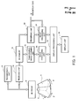
- FIG. 1 is a block diagram illustrating the whole structure of a preferred embodiment of an ultrasonic image processing apparatus according to the present invention.
- the ultrasonic image processing apparatus is configured as an ultrasonic diagnosis apparatus.
- an ultrasonic diagnosis apparatus is an apparatus which is used in the medical field and forms an ultrasonic image by transmission and reception of ultrasound to and from a living organism.
- ultrasound is transmitted and received with respect to a three-dimensional region within a living organism, thereby acquiring volume data.
- a three-dimensional ultrasonic image serving as a volume rendering image or one or more tomographic images are formed, as will be described in detail below.
- a 3D probe 10 is an ultrasonic probe for capturing three-dimensional echo data.
- the 3D probe 10 includes a 1D array transducer and a mechanical scanning mechanism for mechanically scanning the 1D array transducer.
- the 1D array transducer is formed of a plurality of transducer elements which generate an ultrasonic beam.
- the ultrasonic beam is then electronically scanned in the element arrangement direction, thereby forming a scan plane.
- the scan plane is moved in a swinging manner so that a three-dimensional space is formed. In FIG.
- a 2D array transducer may be used to electronically scan an ultrasonic diagnosis apparatus beam in a two-dimensional manner.
- the 3D probe 10 has a transmission/reception plane which is brought into contact with a surface of the living organism.
- the 3D probe 10 is brought into contact with the abdomen of a pregnant woman.
- a transmission unit 12, which is a transmission beam former, supplies a plurality of transmission signals having a predetermined delay relationship to the plurality of transducer elements, thereby forming a transmission beam.
- echoes from within the living organism are received by the plurality of transducer elements, which then output a plurality of reception signals to a receiving unit 14.
- the receiving unit 14 is a receiving beam former; i.e., a phase alignment and summation processing unit in which delay processing is applied to the plurality of reception signals and the plurality of delayed reception signals are summed. Consequently, a receiving beam is electronically formed and a reception signal (beam data) after the phase alignment and summation processing corresponding to the receiving beam is output.
- the beam data are stored in a 3D memory 15.
- the 3D memory 15 includes a storage space (data processing space) corresponding to a three-dimensional space (actual space) in the living organism. Specifically, each echo data item forming the beam data is mapped to a corresponding address within the storage space. With the writing of the data in the 3D memory 15, coordinates conversion processing is applied, or with the reading of the data from the 3D memory 15, coordinates conversion processing is applied.
- a tomographic image forming unit 16 is a module which forms one or a plurality of tomographic images corresponding to one or a plurality of cross-sectional planes which are set with respect to the three-dimensional space.
- Each tomographic image is a monochrome B-mode image.
- the position of each cross sectional plane can be arbitrarily set by a user.
- the tomographic image forming unit 16 reads a set of echo data corresponding to the cross sectional planes which are thus set from the 3D memory and forms a tomographic image based on the read data.
- the tomographic image which is formed is output to a display processing unit 20 via an image processing unit 18.
- the image processing unit 18 has various image processing functions which may include directional (or anisotropic) interpolation processing which will be described below.
- the display processing unit 20 synthesizes a plurality of images to form a single display image and outputs image data representing the display image to a display unit 26.
- a rendering unit 22 is a module which executes volume rendering processing. Specifically, the rendering unit 22 executes processing for forming a three-dimensional image by using the volume data which are read from the 3D memory 15.
- a variety of algorithms have been proposed as rendering methods. More specifically, the rendering unit 22 sets a plurality of rays with respect to the volume data and executes a rendering operation for each ray, thereby computing pixel values.
- a three-dimensional image (original image) is generated as a set of a plurality of pixel values.
- a magnification W is referenced, and the number of rays is determined based on the magnification W.
- the rays are basically thinned out as compared with the conventional art.
- the original image having low resolution is generated with a small number of rays, and then post processing is performed with respect to the original image to thereby form a display image having high resolution.
- An image processing unit 24 is a module which executes the directional interpolation processing. More specifically, the image processing unit 24 also performs change of the magnification (resolution) simultaneously with the interpolation processing, as will be described in detail below. In any case, by applying such directional interpolation processing to the original image, it is possible to generate a display image having an emphasized clear contour, whose resolution or magnification has been changed. Post processing may be further applied to such a display image, as required. In the present embodiment, contrast emphasis processing is applied as the post processing. The image having been subjected to such processing is transmitted to the display processing unit 20. When operations are performed by the image processing unit 24, the magnification W is referenced as required.
- each of the functions illustrated in the stages after the 3D memory 15 is implemented as software processing.
- a control unit which is formed of a CPU and an operation program is omitted in FIG. 1 .
- the directional interpolation processing and the rendering processing described above may be executed by an information processing apparatus such as a computer.
- the volume data supplied from the ultrasonic diagnosis apparatus on-line or off-line is processed by such an information processing apparatus.
- FIG. 2 illustrates the rendering processing and the directional interpolation processing.
- Reference numeral 30 designates a storage space corresponding to a three-dimensional space within a living organism, and in this storage space 30, volume data 31, which in this embodiment are volume data of a fetus, are present.
- a point of view 28 is set at an arbitrary position with respect to the storage space 30 or the volume data 31. Further, a plurality of rays (lines of sight) 34 originating from the point of view 28 are determined. In this case, a plurality of rays 34 are set so as to extend through the volume data 31.
- a screen 32 is a projection plane, and a plurality of pixels on the screen 32 correspond to the plurality of rays on a one-to-one basis.
- reference numeral 32a indicates a pixel.
- the rendering operation i.e., the voxel operation, is executed along each ray sequentially concerning a plurality of voxels (sample points) existing on each ray, and a brightness value serving as a final operation result is mapped as a pixel value of a pixel corresponding to that ray.
- the original image a three-dimensional image
- the original image is formed as a set of a plurality of pixel values.
- the directional interpolation processing i.e., special post processing, which is designated by numeral reference 36
- special post processing which is designated by numeral reference 36
- reference numeral 38a designates pixels forming the display plane 38.
- an apparent resolution can be increased and also the contours can be clarified.
- a speedy rendering operation can be performed by reducing the number of rays in the volume rendering, to thereby lessen the processing load.
- the magnification during the directional interpolation processing is increased, so that a large image can be formed.
- one-view display can be achieved with an amount of three-dimensional computation which is similar to that for a four-view image.
- FIG. 3 illustrates a concept of the directional interpolation processing 36A.
- a view on the left side illustrates an original image 32A
- an image on the right side illustrates a display image (display plane) 38.
- the display image 38 which is enlarged or whose resolution has been increased can be formed. More specifically, each of pixels forming the display image 38 is sequentially determined as a noted point 40.
- a corresponding point (a point of interest) 42 corresponding to a noted point 40 is determined on the original image 32A.
- FIGs. 4 to 6 which will be described below, an interpolated pixel value concerning the noted point is finally obtained, and is mapped as a value of the noted point 40.
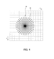
- FIG. 4 illustrates an original image and also illustrates a group of candidate lines 46 extending through the corresponding point.
- the group of candidate lines 46 is formed of a plurality of candidate lines arranged in radial directions, and the angle pitch between two adjacent candidate lines is uniform, and all the candidate lines have the same length. As a matter of course, uneven pitches may be adopted or the length of each line may be set adaptively.
- a dispersion value is computed based on these pixel values. Specifically, an evaluation value indicating the degree of variation of the pixel values is computed.
- a candidate line having the maximum value among these values is determined as illustrated in FIG. 5 .
- a candidate line is represented as a normal line 48A.
- the normal line 48A is set in a direction substantially orthogonal to a peripheral edge 49A of a tissue 49 such that the normal line 48A extends through the corresponding point 42.
- a reference line 48B is further set as a line which is orthogonal to the normal line 48A.
- the reference line 48B is a line along (parallel to) the peripheral edge 49A.
- a plurality of sampling points i.e., a line of sampling points 50 existing on such a reference line 48B, are determined, and with reference to a plurality of pixel values of these sampling points, an interpolated pixel value is computed as an average value or a weighted average value.
- an interpolated pixel value is a brightness value corresponding to the corresponding point 42; more specifically, an interpolated pixel value of the noted point 40 illustrated in FIG. 3 .
- the reference line which is orthogonal to the normal line is obtained
- FIG. 7 illustrates a flowchart for explaining the procedure described above. Specifically, a noted point is set on the display image in step S10, and in step S12 a corresponding point thereof is determined on the original image and a plurality of candidate directions extending through the corresponding point are set.
- step S14 a dispersion value is computed for each of the candidate directions. Then, the candidate direction with the maximum dispersion value is specified as the normal direction in step S16, and further, the reference direction, which is orthogonal to the normal direction, is determined in step S18.
- the reference direction is a direction along the contour of a tissue. As described above, as a matter of course, following step S14, the reference direction may be directly specified by determining the direction with the minimum dispersion value.
- an interpolated pixel value is computed as an average value or a weighted average value thereof.
- a single line of pixel values existing in the reference direction may be referenced or a plurality of lines may be referenced.
- the interpolated pixel value may be obtained by setting a window extending in a rectangular shape and referencing the pixel values in the window.
- FIG. 8 illustrates a plurality of post processing operations to be applied in stages.
- directional interpolation processing is applied, as indicated by a directional interpolation processing unit 52.
- contrast emphasis processing is applied, as indicated by a contrast emphasis processing unit 54.
- the contrast emphasis processing unit 54 includes a gradation determination unit 56, a sharpness determination unit 58, and a sharpness execution unit 60.
- the gradation determination unit 56 is a module which computes an average value within a window having m x m pixels, for example.
- the sharpness determination unit 58 is a module which computes a weight K based on the dispersion value within that window. The function which is used for computing the weight K will be described below with reference to FIG. 9 .
- the sharpening execution unit 60 obtains a pixel value as an output value, based on the pixel value I of a pixel which is currently being noted and the average value I' within the window, and further in consideration of the weight K. More specifically, I + K x(I-I') is computed. This computation is processing in which, if the brightness value of the noted pixel value is greater than the background average brightness value, the brightness value is increased, whereas if the brightness value of the noted pixel value is smaller than the background average brightness value, the brightness value is decreased.
- the weight K is applied as a suppression coefficient.
- the weight K is determined according to the function 62A illustrated in FIG. 9 , for example.
- the horizontal axis represents a dispersion value and the vertical axis represents the weight K.
- the weight K is set to 0.
- such a function 62A is only one example, and the function as indicated by reference numeral 62B can also be used.
- the parameter k for computation of the weight K, it is also possible to increase and decrease the parameter k to thereby allow the user to vary the function shape.
- a parameter k is a coefficient to be multiplied by a dispersion value.
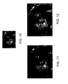
- FIG. 10 illustrates an original image
- FIG. 11 illustrates a result to which conventional linear interpolation processing has been applied to the original image.
- the magnification has been changed.
- FIG. 11 when non-directional general linear interpolation processing is applied, the image quality is significantly lowered. In other words, the image content is blurred.
- FIG. 12 illustrates a result in which the directional interpolation processing is applied to the original image.
- the image quality of the original image is maintained even with the change of magnification, and the image content is rather made superior, in that the contour of a fetus is clearly displayed. Stated inversely, on the precondition that such post processing is to be performed, rapid three-dimensional image formation can be performed even when the number of rays is reduced to decrease the amount of computation.
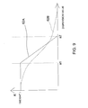
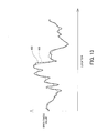
- FIG. 13 illustrates the effects of the post processing described above.
- the horizontal axis represents a location of a pixel and the vertical axis represents a brightness value.
- Numeral reference 100 represents a result of conventional non-directional linear interpolation processing
- numeral reference 102 represents a result of the directional interpolation processing according to the present embodiment. In the latter processing, unevenness is emphasized; particularly, the contour is emphasized, as illustrated, so that image quality is enhanced.
- FIG. 14 illustrates four-view display as an image to be displayed within the display screen 104.
- the four-view display is formed of a 3D image and three B-mode images.
- the three B-mode images are orthogonal to each other.
- FIG. 15 illustrates a two-view display which is formed of a 3D image and a single B-mode image.
- FIG. 16 illustrates a one-view display which is formed of a single 3D image.
- a slightly larger three-dimensional image as illustrated in FIG. 15 or a large three-dimensional image as illustrated in FIG. 16 can be configured. Specifically, it is possible to generate an enlarged three-dimensional image or a three-dimensional image having increased resolution in a simple manner, without increasing the number of rays. Further, control is performed such that the magnification is automatically changed in accordance with the number of views.
- the directional interpolation processing is applied to a three-dimensional image of a fetus
- similar processing may be applied to other tissues.
- the processing described above may be applied to a three-dimensional Doppler image representing blood flow.
- the directional interpolation processing may be applied to information of each color forming the three primary colors.
- contrast processing is applied after the directional interpolation processing in the above embodiment, the latter processing need not be always performed and may be applied as necessary.
Landscapes
- Health & Medical Sciences (AREA)
- Life Sciences & Earth Sciences (AREA)
- Engineering & Computer Science (AREA)
- Physics & Mathematics (AREA)
- Medical Informatics (AREA)
- Animal Behavior & Ethology (AREA)
- Radiology & Medical Imaging (AREA)
- Nuclear Medicine, Radiotherapy & Molecular Imaging (AREA)
- Biomedical Technology (AREA)
- Heart & Thoracic Surgery (AREA)
- Biophysics (AREA)
- Molecular Biology (AREA)
- Surgery (AREA)
- Pathology (AREA)
- General Health & Medical Sciences (AREA)
- Public Health (AREA)
- Veterinary Medicine (AREA)
- General Physics & Mathematics (AREA)
- Theoretical Computer Science (AREA)
- Ultra Sonic Daignosis Equipment (AREA)
- Image Processing (AREA)
- Image Analysis (AREA)
Applications Claiming Priority (1)
| Application Number | Priority Date | Filing Date | Title |
|---|---|---|---|
| JP2010187874A JP5632680B2 (ja) | 2010-08-25 | 2010-08-25 | 超音波画像処理装置 |
Publications (1)
| Publication Number | Publication Date |
|---|---|
| EP2423872A1 true EP2423872A1 (en) | 2012-02-29 |
Family
ID=44674032
Family Applications (1)
| Application Number | Title | Priority Date | Filing Date |
|---|---|---|---|
| EP20110006351 Withdrawn EP2423872A1 (en) | 2010-08-25 | 2011-08-02 | Ultrasonic image processing apparatus |
Country Status (4)
| Country | Link |
|---|---|
| US (1) | US9123139B2 (enExample) |
| EP (1) | EP2423872A1 (enExample) |
| JP (1) | JP5632680B2 (enExample) |
| CN (1) | CN102436672B (enExample) |
Families Citing this family (16)
| Publication number | Priority date | Publication date | Assignee | Title |
|---|---|---|---|---|
| JP5896389B2 (ja) * | 2011-12-13 | 2016-03-30 | エンパイア テクノロジー ディベロップメント エルエルシー | ディスプレイのためのグラフィックスレンダリングの整合 |
| AU2012202349B2 (en) * | 2012-04-20 | 2015-07-30 | Canon Kabushiki Kaisha | Image resampling by frequency unwrapping |
| JP6293578B2 (ja) * | 2014-05-28 | 2018-03-14 | ジーイー・メディカル・システムズ・グローバル・テクノロジー・カンパニー・エルエルシー | 超音波診断装置及びプログラム |
| JP5946197B2 (ja) * | 2014-07-11 | 2016-07-05 | 株式会社日立製作所 | 超音波診断装置 |
| US10169909B2 (en) * | 2014-08-07 | 2019-01-01 | Pixar | Generating a volumetric projection for an object |
| WO2017092615A1 (zh) * | 2015-11-30 | 2017-06-08 | 上海联影医疗科技有限公司 | 一种计算机辅助诊断系统及方法 |
| US10963991B2 (en) * | 2016-07-25 | 2021-03-30 | Nec Corporation | Information processing device, information processing method, and recording medium |
| EP3422048A1 (en) * | 2017-06-26 | 2019-01-02 | Koninklijke Philips N.V. | Ultrasound imaging method and system |
| KR102053527B1 (ko) * | 2017-10-15 | 2019-12-06 | 알레시오 주식회사 | 이미지 처리 방법 |
| WO2019074339A1 (ko) * | 2017-10-15 | 2019-04-18 | 알레시오 주식회사 | 신호 변환 시스템 및 신호 변환 방법 |
| CN107845082B (zh) * | 2017-12-14 | 2021-10-15 | 飞依诺科技(苏州)有限公司 | 一种用于提高局部区域的对比度的方法和装置 |
| CN112168210B (zh) * | 2019-07-03 | 2024-04-16 | 深圳迈瑞生物医疗电子股份有限公司 | 医学图像处理终端、超声诊断设备和胎儿图像的处理方法 |
| CN113870169B (zh) * | 2020-06-12 | 2023-12-01 | 杭州普健医疗科技有限公司 | 一种医学影像标注方法、介质及电子设备 |
| US12337232B2 (en) * | 2021-01-04 | 2025-06-24 | Microsoft Technology Licensing, Llc | Systems and methods for streaming interactive applications |
| CN112870711B (zh) * | 2021-04-28 | 2021-07-16 | 腾讯科技(深圳)有限公司 | 一种云游戏的处理方法、装置、设备及存储介质 |
| CN113892967B (zh) * | 2021-09-07 | 2023-10-27 | 青岛海信医疗设备股份有限公司 | 一种超声图像的处理方法和超声仪器 |
Citations (6)
| Publication number | Priority date | Publication date | Assignee | Title |
|---|---|---|---|---|
| EP0550231A1 (en) * | 1991-12-31 | 1993-07-07 | Salon Televisiotehdas Oy | Method for edge-adaptive interpolation of a television picture |
| EP0565948A2 (en) * | 1992-04-14 | 1993-10-20 | NOKIA TECHNOLOGY GmbH | Procedure and circuit arrangement for doubling the vertical and horizontal resolution of picture displayed on the screen |
| JPH1033538A (ja) | 1995-07-17 | 1998-02-10 | Aloka Co Ltd | 超音波画像処理装置及び方法 |
| US6310631B1 (en) * | 1996-04-26 | 2001-10-30 | International Business Machines Corporation | User interface control for creating split panes in a single window |
| US20070173723A1 (en) * | 2001-02-01 | 2007-07-26 | Hiroshi Kanda | Ultrasonic enhanced-contrast imager and method |
| JP2010000125A (ja) | 2008-06-18 | 2010-01-07 | Aloka Co Ltd | 超音波診断装置 |
Family Cites Families (14)
| Publication number | Priority date | Publication date | Assignee | Title |
|---|---|---|---|---|
| EP0754957B1 (en) | 1995-07-17 | 2001-03-21 | Aloka Co. Ltd. | Ultrasound image processing apparatus and method for producing an ultrasound image |
| JP3462957B2 (ja) * | 1996-06-11 | 2003-11-05 | 株式会社日立製作所 | 画像処理方法 |
| US6674879B1 (en) * | 1998-03-30 | 2004-01-06 | Echovision, Inc. | Echocardiography workstation |
| JP3542779B2 (ja) * | 2001-04-12 | 2004-07-14 | ザイオソフト株式会社 | 3次元画像表示方法 |
| US6878115B2 (en) * | 2002-03-28 | 2005-04-12 | Ultrasound Detection Systems, Llc | Three-dimensional ultrasound computed tomography imaging system |
| JP2004141514A (ja) | 2002-10-28 | 2004-05-20 | Toshiba Corp | 画像処理装置及び超音波診断装置 |
| EP1634248B1 (en) | 2003-06-05 | 2008-10-08 | Philips Intellectual Property & Standards GmbH | Adaptive image interpolation for volume rendering |
| JP4534594B2 (ja) * | 2004-05-19 | 2010-09-01 | ソニー株式会社 | 画像処理装置、画像処理方法、画像処理方法のプログラム及び画像処理方法のプログラムを記録した記録媒体 |
| JP4299189B2 (ja) | 2004-05-27 | 2009-07-22 | アロカ株式会社 | 超音波診断装置及び画像処理方法 |
| US7601121B2 (en) * | 2004-07-12 | 2009-10-13 | Siemens Medical Solutions Usa, Inc. | Volume rendering quality adaptations for ultrasound imaging |
| JP4188900B2 (ja) * | 2004-11-15 | 2008-12-03 | ザイオソフト株式会社 | 医療画像処理プログラム |
| JP4653536B2 (ja) * | 2005-03-29 | 2011-03-16 | アロカ株式会社 | 超音波診断装置 |
| JP5044144B2 (ja) * | 2006-05-24 | 2012-10-10 | 株式会社東芝 | 医用画像形成装置 |
| CN101190132B (zh) | 2006-11-28 | 2010-12-08 | 深圳迈瑞生物医疗电子股份有限公司 | 超声成像的预处理方法与装置 |
-
2010
- 2010-08-25 JP JP2010187874A patent/JP5632680B2/ja active Active
-
2011
- 2011-08-02 EP EP20110006351 patent/EP2423872A1/en not_active Withdrawn
- 2011-08-17 US US13/211,781 patent/US9123139B2/en active Active
- 2011-08-24 CN CN201110251406.3A patent/CN102436672B/zh active Active
Patent Citations (6)
| Publication number | Priority date | Publication date | Assignee | Title |
|---|---|---|---|---|
| EP0550231A1 (en) * | 1991-12-31 | 1993-07-07 | Salon Televisiotehdas Oy | Method for edge-adaptive interpolation of a television picture |
| EP0565948A2 (en) * | 1992-04-14 | 1993-10-20 | NOKIA TECHNOLOGY GmbH | Procedure and circuit arrangement for doubling the vertical and horizontal resolution of picture displayed on the screen |
| JPH1033538A (ja) | 1995-07-17 | 1998-02-10 | Aloka Co Ltd | 超音波画像処理装置及び方法 |
| US6310631B1 (en) * | 1996-04-26 | 2001-10-30 | International Business Machines Corporation | User interface control for creating split panes in a single window |
| US20070173723A1 (en) * | 2001-02-01 | 2007-07-26 | Hiroshi Kanda | Ultrasonic enhanced-contrast imager and method |
| JP2010000125A (ja) | 2008-06-18 | 2010-01-07 | Aloka Co Ltd | 超音波診断装置 |
Non-Patent Citations (7)
| Title |
|---|
| FENSTER A ET AL: "3-D ULTRASOUND IMAGING: A REVIEW", IEEE ENGINEERING IN MEDICINE AND BIOLOGY MAGAZINE, IEEE SERVICE CENTER, PISACATAWAY, NJ, US, vol. 15, no. 6, 1 November 1996 (1996-11-01), pages 41 - 51, XP000638027 * |
| KAJIYA J. T. ET AL.: "Ray Tracing Volume Densities", PROCEEDINGS OF THE SIGGRAPH '84, ACM, NY, USA, vol. 18, no. 3, July 1984 (1984-07-01), pages 165 - 174 * |
| SAKAS G ET AL: "Preprocessing and volume rendering of 3D ultrasonic data", IEEE COMPUTER GRAPHICS AND APPLICATIONS, IEEE SERVICE CENTER, NEW YORK, NY, US, vol. 15, no. 4, 1 July 1995 (1995-07-01), pages 47 - 54, XP002276298 * |
| STEEN E ET AL: "VOLUME RENDERING OF 3D MEDICAL ULTRASOUND DATA USING DIRECT FEATUREMAPPING", IEEE TRANSACTIONS ON MEDICAL IMAGING, IEEE SERVICE CENTER, PISCATAWAY, NJ, US, vol. 13, no. 3, 1 September 1994 (1994-09-01), pages 517 - 525, XP000474142 * |
| THURNHOFER S ET AL: "EDGE-ENHANCED IMAGE ZOOMING", OPTICAL ENGINEERING, SOC. OF PHOTO-OPTICAL INSTRUMENTATION ENGINEERS, BELLINGHAM, vol. 35, no. 7, 1 July 1996 (1996-07-01), pages 1862 - 1869, XP000631007 * |
| W.WAYT GIBBS: "A Great Leap in Graphics", SCIENTIFIC AMERICAN, vol. 295, no. 2, August 2006 (2006-08-01), pages 80 - 84 * |
| YAO WANG ET AL: "EDGE PRESERVED IMAGE ZOOMING", SIGNAL PROCESSING : THEORIES AND APPLICATIONS. GRENOBLE, SEPT. 5 - 8, 1988; PROCEEDINGS OF THE EUROPEAN SIGNAL PROCESSING CONFERENCE (EUSIPCO), AMSTERDAM, NORTH HOLLAND, NL, vol. 3, 5 September 1988 (1988-09-05), pages 1445 - 1448, XP000093910 * |
Also Published As
| Publication number | Publication date |
|---|---|
| JP5632680B2 (ja) | 2014-11-26 |
| CN102436672B (zh) | 2014-11-26 |
| JP2012045065A (ja) | 2012-03-08 |
| US20120053464A1 (en) | 2012-03-01 |
| US9123139B2 (en) | 2015-09-01 |
| CN102436672A (zh) | 2012-05-02 |
Similar Documents
| Publication | Publication Date | Title |
|---|---|---|
| US9123139B2 (en) | Ultrasonic image processing with directional interpolation in order to increase the resolution of an image | |
| EP2016905B1 (en) | Ultrasound diagnostic apparatus | |
| CN101396287B (zh) | 超声波诊断装置以及超声波诊断图像生成方法 | |
| EP2453406B1 (en) | Ultrasonic image processing apparatus | |
| JP4628645B2 (ja) | 複数の2dスライスから画像を作成するための超音波診断方法及び装置 | |
| US20110125016A1 (en) | Fetal rendering in medical diagnostic ultrasound | |
| EP1600891A1 (en) | Ultrasonic diagnostic apparatus and image processing method | |
| EP3669371A1 (en) | Ultrasound system with deep learning network for image artifact identification and removal | |
| US9039620B2 (en) | Ultrasound diagnostic apparatus | |
| JP2010029281A (ja) | 超音波診断装置 | |
| CN103118600B (zh) | 超声波诊断装置以及超声波图像的显示方法 | |
| JP2018153561A (ja) | 超音波画像処理装置 | |
| JP2022521060A (ja) | 反転データのセグメント化、レンダリングの方法及びシステム | |
| JP4679095B2 (ja) | 画像処理装置、画像処理方法、及びプログラム | |
| CN117297662A (zh) | 超声波图像处理装置以及计算机可读的非临时性的存储介质 | |
| JP5950291B1 (ja) | 超音波診断装置及びプログラム | |
| JP7432426B2 (ja) | 超音波診断装置、信号処理装置および信号処理プログラム | |
| US10255661B2 (en) | Object information acquiring apparatus and image processing method | |
| JP6793075B2 (ja) | 超音波画像処理装置 | |
| JP2024092213A (ja) | 超音波診断装置 | |
| JP2017153726A (ja) | 超音波画像処理装置 |
Legal Events
| Date | Code | Title | Description |
|---|---|---|---|
| AK | Designated contracting states |
Kind code of ref document: A1 Designated state(s): AL AT BE BG CH CY CZ DE DK EE ES FI FR GB GR HR HU IE IS IT LI LT LU LV MC MK MT NL NO PL PT RO RS SE SI SK SM TR |
|
| AX | Request for extension of the european patent |
Extension state: BA ME |
|
| PUAI | Public reference made under article 153(3) epc to a published international application that has entered the european phase |
Free format text: ORIGINAL CODE: 0009012 |
|
| 17P | Request for examination filed |
Effective date: 20120829 |
|
| 17Q | First examination report despatched |
Effective date: 20130319 |
|
| RAP1 | Party data changed (applicant data changed or rights of an application transferred) |
Owner name: HITACHI, LTD. |
|
| STAA | Information on the status of an ep patent application or granted ep patent |
Free format text: STATUS: THE APPLICATION HAS BEEN WITHDRAWN |
|
| 18W | Application withdrawn |
Effective date: 20170706 |