EP2423381A1 - Rubber/steel cord composite and pneumatic radial tire - Google Patents
Rubber/steel cord composite and pneumatic radial tire Download PDFInfo
- Publication number
- EP2423381A1 EP2423381A1 EP10766834A EP10766834A EP2423381A1 EP 2423381 A1 EP2423381 A1 EP 2423381A1 EP 10766834 A EP10766834 A EP 10766834A EP 10766834 A EP10766834 A EP 10766834A EP 2423381 A1 EP2423381 A1 EP 2423381A1
- Authority
- EP
- European Patent Office
- Prior art keywords
- rubber
- cord
- core
- filler
- coating
- Prior art date
- Legal status (The legal status is an assumption and is not a legal conclusion. Google has not performed a legal analysis and makes no representation as to the accuracy of the status listed.)
- Granted
Links
Images


Classifications
-
- B—PERFORMING OPERATIONS; TRANSPORTING
- B60—VEHICLES IN GENERAL
- B60C—VEHICLE TYRES; TYRE INFLATION; TYRE CHANGING; CONNECTING VALVES TO INFLATABLE ELASTIC BODIES IN GENERAL; DEVICES OR ARRANGEMENTS RELATED TO TYRES
- B60C9/00—Reinforcements or ply arrangement of pneumatic tyres
- B60C9/0007—Reinforcements made of metallic elements, e.g. cords, yarns, filaments or fibres made from metal
-
- D—TEXTILES; PAPER
- D07—ROPES; CABLES OTHER THAN ELECTRIC
- D07B—ROPES OR CABLES IN GENERAL
- D07B1/00—Constructional features of ropes or cables
- D07B1/06—Ropes or cables built-up from metal wires, e.g. of section wires around a hemp core
- D07B1/0606—Reinforcing cords for rubber or plastic articles
- D07B1/0666—Reinforcing cords for rubber or plastic articles the wires being characterised by an anti-corrosive or adhesion promoting coating
-
- D—TEXTILES; PAPER
- D07—ROPES; CABLES OTHER THAN ELECTRIC
- D07B—ROPES OR CABLES IN GENERAL
- D07B1/00—Constructional features of ropes or cables
- D07B1/16—Ropes or cables with an enveloping sheathing or inlays of rubber or plastics
- D07B1/162—Ropes or cables with an enveloping sheathing or inlays of rubber or plastics characterised by a plastic or rubber enveloping sheathing
-
- D—TEXTILES; PAPER
- D07—ROPES; CABLES OTHER THAN ELECTRIC
- D07B—ROPES OR CABLES IN GENERAL
- D07B1/00—Constructional features of ropes or cables
- D07B1/16—Ropes or cables with an enveloping sheathing or inlays of rubber or plastics
- D07B1/165—Ropes or cables with an enveloping sheathing or inlays of rubber or plastics characterised by a plastic or rubber inlay
-
- B—PERFORMING OPERATIONS; TRANSPORTING
- B60—VEHICLES IN GENERAL
- B60C—VEHICLE TYRES; TYRE INFLATION; TYRE CHANGING; CONNECTING VALVES TO INFLATABLE ELASTIC BODIES IN GENERAL; DEVICES OR ARRANGEMENTS RELATED TO TYRES
- B60C9/00—Reinforcements or ply arrangement of pneumatic tyres
- B60C9/0007—Reinforcements made of metallic elements, e.g. cords, yarns, filaments or fibres made from metal
- B60C2009/0021—Coating rubbers for steel cords
-
- D—TEXTILES; PAPER
- D07—ROPES; CABLES OTHER THAN ELECTRIC
- D07B—ROPES OR CABLES IN GENERAL
- D07B1/00—Constructional features of ropes or cables
- D07B1/06—Ropes or cables built-up from metal wires, e.g. of section wires around a hemp core
- D07B1/0606—Reinforcing cords for rubber or plastic articles
- D07B1/0613—Reinforcing cords for rubber or plastic articles the reinforcing cords being characterised by the rope configuration
-
- D—TEXTILES; PAPER
- D07—ROPES; CABLES OTHER THAN ELECTRIC
- D07B—ROPES OR CABLES IN GENERAL
- D07B1/00—Constructional features of ropes or cables
- D07B1/06—Ropes or cables built-up from metal wires, e.g. of section wires around a hemp core
- D07B1/0606—Reinforcing cords for rubber or plastic articles
- D07B1/062—Reinforcing cords for rubber or plastic articles the reinforcing cords being characterised by the strand configuration
- D07B1/0626—Reinforcing cords for rubber or plastic articles the reinforcing cords being characterised by the strand configuration the reinforcing cords consisting of three core wires or filaments and at least one layer of outer wires or filaments, i.e. a 3+N configuration
-
- D—TEXTILES; PAPER
- D07—ROPES; CABLES OTHER THAN ELECTRIC
- D07B—ROPES OR CABLES IN GENERAL
- D07B2201/00—Ropes or cables
- D07B2201/20—Rope or cable components
- D07B2201/2015—Strands
- D07B2201/2046—Strands comprising fillers
-
- D—TEXTILES; PAPER
- D07—ROPES; CABLES OTHER THAN ELECTRIC
- D07B—ROPES OR CABLES IN GENERAL
- D07B2201/00—Ropes or cables
- D07B2201/20—Rope or cable components
- D07B2201/2047—Cores
- D07B2201/2052—Cores characterised by their structure
- D07B2201/2059—Cores characterised by their structure comprising wires
- D07B2201/2061—Cores characterised by their structure comprising wires resulting in a twisted structure
-
- D—TEXTILES; PAPER
- D07—ROPES; CABLES OTHER THAN ELECTRIC
- D07B—ROPES OR CABLES IN GENERAL
- D07B2201/00—Ropes or cables
- D07B2201/20—Rope or cable components
- D07B2201/2047—Cores
- D07B2201/2052—Cores characterised by their structure
- D07B2201/2059—Cores characterised by their structure comprising wires
- D07B2201/2062—Cores characterised by their structure comprising wires comprising fillers
-
- D—TEXTILES; PAPER
- D07—ROPES; CABLES OTHER THAN ELECTRIC
- D07B—ROPES OR CABLES IN GENERAL
- D07B2201/00—Ropes or cables
- D07B2201/20—Rope or cable components
- D07B2201/2047—Cores
- D07B2201/2052—Cores characterised by their structure
- D07B2201/2065—Cores characterised by their structure comprising a coating
-
- D—TEXTILES; PAPER
- D07—ROPES; CABLES OTHER THAN ELECTRIC
- D07B—ROPES OR CABLES IN GENERAL
- D07B2207/00—Rope or cable making machines
- D07B2207/20—Type of machine
- D07B2207/204—Double twist winding
- D07B2207/205—Double twist winding comprising flyer
-
- D—TEXTILES; PAPER
- D07—ROPES; CABLES OTHER THAN ELECTRIC
- D07B—ROPES OR CABLES IN GENERAL
- D07B2207/00—Rope or cable making machines
- D07B2207/40—Machine components
- D07B2207/4072—Means for mechanically reducing serpentining or mechanically killing of rope
-
- D—TEXTILES; PAPER
- D07—ROPES; CABLES OTHER THAN ELECTRIC
- D07B—ROPES OR CABLES IN GENERAL
- D07B2501/00—Application field
- D07B2501/20—Application field related to ropes or cables
- D07B2501/2046—Tire cords
-
- D—TEXTILES; PAPER
- D07—ROPES; CABLES OTHER THAN ELECTRIC
- D07B—ROPES OR CABLES IN GENERAL
- D07B7/00—Details of, or auxiliary devices incorporated in, rope- or cable-making machines; Auxiliary apparatus associated with such machines
- D07B7/02—Machine details; Auxiliary devices
- D07B7/14—Machine details; Auxiliary devices for coating or wrapping ropes, cables, or component strands thereof
- D07B7/145—Coating or filling-up interstices
Definitions
- the present invention relates to a rubber-steel hybrid cord used as a reinforcing member for a pneumatic radial tire and to a pneumatic radial tire having a reinforcement layer formed using the rubber-steel hybrid cord.
- cords used for reinforcing a pneumatic radial tire Since high strength is required of cords used for reinforcing a pneumatic radial tire, a cord made by twisting a plurality of sheath filaments around a core filament, or a cord having a so-called multilayer-twist structure in which a plurality of filaments are twisted around a core strand and a plurality of sheath strands are further twisted around the core strand, is used for this purpose. These cords are aligned and covered with a sheet-like coating rubber to obtain a hybrid rubber cord can be obtained.
- Such coating rubber contains an adhesion promoter component for promoting adhesion with a cord such as a steel cord, and a great amount of sulfur.
- Cobalt salts of organic acids are typical for such an adhesion promoter; however, when a cobalt salt of an organic acid is contained in a high proportion, it would react with a vulcanization accelerator, an age resistor, or the like to impair adhesiveness or aging resistance of the rubber after being left in an unvulcanized state.
- sulfur is contained in a high proportion, a problem may arise in that vulcanization would proceed excessively before a vulcanization step to deteriorate the rubber properties after vulcanization.
- any of such hybrid rubber cords are not so helpful to overcome the above-mentioned problems caused by a high proportion of an adhesion promoter or sulfur.
- an object of the present invention is to provide a rubber-steel hybrid cord which makes it possible to sufficiently reduce the proportion of an adhesion promoter or sulfur while maintaining good adhesiveness, and to provide a pneumatic radial tire using the same as a reinforcement layer.
- the present inventor focused on a phenomenon that the provision of a filler rubber layer on a core diffuses and transfers an adhesion promoter and sulfur from the coating rubber to the filler rubber at the time of vulcanization and found a rubber-steel hybrid cord utilizing the phenomenon to accomplish the present invention.
- the rubber-steel hybrid cord of the present invention is characteristically formed by twisting a plurality of sheath filaments or sheath strands around a core in which a periphery of and space surrounded by one or a plurality of core filaments or a core strand are coated or filled with a filler rubber (A) containing an adhesion promoter, thereby forming a multilayer-twist steel cord or a multi-twist steel cord, and coating an outer surface of the multilayer-twist steel cord or the multi-twist steel cord with a coating rubber (C).
- A filler rubber
- C coating rubber
- an amount of an adhesion promoter contained in the coating rubber (C) is equal to or more than an amount of the adhesion promoter contained in the filler rubber (A).
- the filler rubber (A) does not contain any adhesion promoter.
- a pneumatic radial tire according to the present invention characteristically includes a reinforcement layer made of such a rubber-steel hybrid cord.
- a rubber-steel hybrid cord according to the present invention uses a filler rubber containing an adhesion promoter the amount of which is reduced to a minimum; therefore, reduction in aging resistance of the filler rubber in the cord can be prevented effectively as a whole. Further, the presence of a filler rubber in a core can increase the area of contact between filaments or strands of the core and the rubber, which allows the adhesion to be stronger and to have higher durability.
- the amount of sulfur in the filler rubber can be reduced effectively, which can effectively suppress advancement of vulcanization in vulcanization in progress or before a vulcanization step in fabricating a cord.
- a rubber-steel hybrid cord of the present invention as a reinforcement layer, a pneumatic radial tire with excellent durability can be realized.
- Fig. 1 shows a cross section of a cord according to the present invention, which is perpendicular to the axial directions of the cord.
- Fig. 1 shows a steel cord used for a rubber-steel hybrid cord of the present invention, which is a multilayer-twist steel cord 3a made by twisting filaments (or strands) having the same diameter, in which nine sheath filaments (or sheath strands) 2a forming a sheath 2 are twisted around a core 1 including 3 core filaments (or a core strand) 1a.
- This multilayer-twist steel cord 3a has a filler rubber (A) layer 4 between the core 1 and the sheath 2 as shown with hatch lines in Fig. 1 .
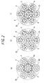
- Fig. 2(a) shows a multi-twist steel cord having a filler rubber (A) layer 4 around a core strand 5
- Fig. 2(b) shows a multi-twist steel cord in which a plurality of steel cords shown in Fig. 1 are twisted together
- Fig. 2(c) shows a multi-twist steel cord formed by coating a plurality of steel cords shown in Fig. 1 that are twisted together are further coated with a filler rubber (A).
- a rubber-steel hybrid cord of the present invention is formed by twisting a plurality of sheath filaments (or sheath strands) around a core made by coating or filling the periphery of and the space surrounded by the one or plurality of core filaments (or the core strand) with the filler rubber (A) to form multilayer-twist steel cords (or multi-twist steel cords), and coating the outer surfaces of the steel cords with a coating rubber (C).
- the rubber-steel hybrid cord has a rubber layer composed of two layers of the filler rubber (A) layer 4 and the coating rubber (C) layer 7.
- the periphery of and the space surrounded by the core filaments (or core strand) are not coated or filled with the filler rubber (A), for example as shown in Fig. 3(b) .
- a rubber-steel hybrid cord of the present invention is formed through coating or filling with the filler rubber (A) as described above, thus achieving strong adhesiveness between these core filaments (or core strand) and the rubber and high durability. Further, the filler rubber (A) suppresses fretting and improves corrosion fatigue resistance.
- Fig. 2 shows an aspect in which the periphery of and the space surrounded by the core filaments forming the core strand is not coated or filled with the filler rubber (A); however, the periphery of and the space surrounded by each filament may be coated or filled with the filler rubber (A).
- Steel for forming a cord used for the present invention is not limited in particular; however, the filaments (or strands) are preferably brass-coated by means of typical methods such as plating methods, various CVD methods, or PVD methods to improve adhesiveness to a vulcanized rubber.
- a rubber ingredient used for the filler rubber (A) and the coating rubber (C) is not limited as long as it can be used for a tire.
- the rubber ingredient include natural rubber (NR) and synthetic rubbers such as polybutadiene rubber (BR), styrene butadiene copolymer rubber (SBR), styrene isoprene copolymer rubber (SIR), polyisoprene rubber (IR), butyle rubber (IIR), acrylonitrile-butadiene rubber, chloroprene rubber, and ethylene-propylene copolymers; however, it is desirable to use natural rubber (NR) alone.
- BR polybutadiene rubber
- SBR styrene butadiene copolymer rubber
- SIR styrene isoprene copolymer rubber
- IR polyisoprene rubber
- IIR butyle rubber
- acrylonitrile-butadiene rubber chloroprene rubber
- an additive agent In addition to the above rubber ingredients, an additive agent, an adhesion promoter, or the like is added as appropriate depending on respective characteristics required of the filler rubber (A) and the coating rubber (C).
- the additive agent may be a filler; for example, a carbon black such as SRF, GPF, FER, HAF, or ISAF; silica; calcium carbonate; talc; or the like can be used.
- a carbon black such as SRF, GPF, FER, HAF, or ISAF
- silica silica
- calcium carbonate calcium carbonate
- talc or the like
- the amount of the carbon black is preferably 40 to 60 parts by mass relative to 100 parts by mass of the rubber component.
- the adhesion promoter may be a cobalt salt of an organic acid; for example, cobalt naphthenate, cobalt rosinate, linear or branched cobalt monocarboxylate having about 5 to 20 carbon atoms, or the like can be used.
- a vulcanizing agent such as sulfur, an age resistor, a vulcanization accelerator, a processing aid such as zinc oxide, an antiozonant, a plasticizer, or the like can be added.
- a processing aid such as zinc oxide, an antiozonant, a plasticizer, or the like
- the amount of the adhesion promoter contained in the filler rubber (A) is equal to or less than the amount of the adhesion promoter contained in the coating rubber (C) to be described below, preferably less than the amount of the adhesion promoter contained in the coating rubber (C). More preferably, the filler rubber (A) does not contain any adhesion promoter. Specifically, the amount of the filler rubber (A) is usually 0 to 3.0 parts by mass and preferably 0 parts by mass relative to 100 parts by mass of the rubber component.
- the amount of the adhesion promoter contained in the filler rubber (A) is reduced, an adhesion promoter diffuses and transfers from the coating rubber (C) at the time of vulcanization. Therefore, good adhesiveness can be maintained sufficiently. Besides, the amount within the above range can effectively reduce reaction to the vulcanization accelerator, age resistor, or the like added to the filler rubber (A), and suppress decrease in the adhesiveness and aging resistance when being left unvulcanized.
- the sulfur content is preferably equal to or less than the amount of sulfur contained in the coating rubber (C), preferably less than the amount of sulfur contained in the coating rubber (C).
- the amount is usually 3.0 to 7.0 parts by mass and preferably 3.0 to 5.0 parts by mass relative to 100 parts by mass of the rubber component.
- the amount of the adhesion promoter contained in the coating rubber (C) is equal to or more than the amount of the adhesion promoter contained in the above filler rubber (A), preferably more than the amount of the adhesion promoter contained in the filler rubber (A). Specifically, the amount is usually 1.0 to 5.0 parts by mass, preferably 1.0 to 3.0 parts by mass relative to 100 parts by mass of the rubber component. When the amount is equal to or more than the lower limit mentioned above, even if the adhesion promoter diffuses and transfers to the filler rubber (A), a sufficient amount of the adhesion promoter can remain in the coating rubber (C) after vulcanization. Thus, even the initial adhesiveness would not be reduced more than necessary while maintaining excellent deterioration adhesiveness to the steel cords.
- the amount of sulfur contained is equal to or more than the amount of sulfur contained in the filler rubber (A), and preferably more than the amount of sulfur contained in the filler rubber (A). Specifically, the amount is usually 3.0 to 7.0 parts by mass and preferably 5.0 to 7.0 parts by mass relative to 100 parts by mass of the rubber component.
- the amount is equal to or more than the above lower limit, even if sulfur diffuses and transfers to the adhesion promoter, a sufficient amount of the adhesion promoter can remain in the coating rubber (C) at the time of vulcanization. Thus, excellent adhesiveness to the steel cords can be achieved effectively.
- the sulfur content exceeds the upper limit mentioned above, fatigue fracture resistance would decrease.
- a cord is produced first using, for example, a cord production system shown in Fig. 4 .
- the cord production system is equipped with a core supply 9 which supplies a core portion 9a formed by twisting a plurality of core filaments together and a given number of sheath supplies 10 which supply sheath filaments 10a, and is provided with a wire collector 11 which collects the filaments wound off from each supply, and a wire twisting machine 12 twists the collected filaments together.
- a rubber coater 13 for coating the core portion 9a with an unvulcanized filler rubber (A) is provided between the core supply 9 and the wire collector 11.
- a core portion 9a wound around the core supply 9 is would off first to be lead to the rubber coater 13 side, the core portion 9a is coated with the filler rubber (A) by means of the rubber coater 13 to form a rubber-coated filament 13a.
- the rubber-coated filament 13a is supplied to the wire collector 11 provided on the side of entrance to the wire twisting machine 12, the sheath filaments 10a wound off from the sheath supplies 10 are collected around the rubber-coated filament 13a by the wire collector 11 to form a bundled filaments 11 a, and the bundled filaments 11 a are supplied to the wire twisting machine 12. After that, the bundled filaments 11 a are twisted together by the wire twisting machine 12 to form a cord 15.
- the core portion 9a wound off from the core supply 9 is preferably supplied to the wire twisting machine 12 after being coated with a given amount of the filler rubber (A) as described below.
- the given amount of the filler rubber (A) filler rubber (A) layer 4
- the filler rubber (A) can be prevented from protruding beyond necessity between the sheath filaments twisted together to form the cord.
- the interspace in the core portion 9a is filled with an appropriate amount of the filler rubber (A).
- the given amount of the filler rubber (A) is an amount which satisfies A ⁇ B ⁇ 10A, wherein A denotes the area A of the interspace between the core and sheaths and B denotes the area B of the filler rubber (A) layer occupying the space between the core and the sheaths in a cross section perpendicular to the axial directions of the cord.
- the area A of the interspace between the core and the sheaths is defined on the basis of a closed cord.
- a closed cord having the same structure as Fig. 1
- the interspace between the core and the sheaths in the cross section perpendicular to the axial directions of the cord having a closed structure shown in Fig. 5(a) ⁇ the dotted area in Fig. 5 ⁇ is defined as the area A.
- the interspace between the sheaths 28 which does not involve the core 27 is excluded.
- the area B of the filler rubber (A) layer 4 occupying the space between the core 27 and the sheaths 28 corresponds to a rubber portion covering the periphery of the core (hatched area).
- the periphery of the core filaments may be coated with the filler rubber (A) corresponding to the area B and then, the sheath filaments may be entwisted.
- the rubber coater 13 for coating the core portion 9a with the filler rubber (A) has, for example, a rubber extruder 16 and a rubber extruder head portion 18 as shown in Fig. 6 .
- rubber 19 is extruded from the rubber extruder 16 side through the rubber extruder screw 17 to the rubber extruder head portion 18 to fill the inside of the rubber extruder head portion 18 with the filler rubber (A).
- the core portion 9a is supplied to the rubber extruder head portion 18 through a cord guide 20 provided on the side of entrance to the rubber extruder head portion 18, and the periphery of the core portion 9a is coated with the filler rubber (A) 19 while being passed through the rubber extruder head portion 18.
- the core portion 9a coated with the filler rubber (A) 19 is lead to the outside of the rubber extruder head portion 18 through a base cap 21 provided on the side of exit from the rubber extruder head portion 18 while the thickness of the coating rubber (B) is controlled to form a filler rubber (A)-coated filament 13a.
- the obtained plurality of cords are arranged in parallel at intervals of 1.5 mm to 2.0 mm, coated with the coating rubber (C) from above and below, and cut with a width and at an angle depending on the desired portion, thereby obtaining a rubber-steel hybrid cord.
- Fig. 7 shows an example of a production system used especially for producing multi-twist steel cords.
- This cord system is provided with a core strand supply 50 which supplies a core strand 50a, and provided with a rubber coater 53 including a rubber extruder 5 and a rubber extruder head portion 52 for coating a core strand 50a with the unvulcanized filler rubber (A) between the core strand supply 50 and the sheath strand supplies 55.
- A unvulcanized filler rubber
- the core strand 50a lead from the rubber extruder head portion 52 of the rubber coater 53 is supplied to the sheath strand supplies 55 provided separately for supplying sheath strands 55a, shaped through a straightener 56 to form a multi-twist cord 57a, which is transferred to a multi-twist cord reel 57.
- coating with the coating rubber (C) is performed in a manner similar to the above to obtain a rubber-steel hybrid cord.
- a rubber-steel hybrid cord of the present invention is employed as a reinforcement layer of a belt layer, a carcass layer, or a bead portion of a pneumatic radial tire, which allows adhesion durability, aging resistance, fatigue fracture resistance, and the like of this reinforcement layer to improve. Accordingly, a high-performance pneumatic radial tire having excellent durability can be realized.
- Rubbers were formed in accordance with the compositions shown in Table 2, and steel cords and a rubber-steel hybrid cords of the aspect shown in the schematic view of Fig. 3(a) were fabricated using the rubbers by the above-mentioned method and evaluated with respect to the evaluation items below. Note that conventional rubber-steel hybrid cords in which steel cords were coated with only a coating rubber (C) as shown in the schematic view of Fig. 3(b) were fabricated as Reference 1 and Comparative Examples 1 to 2.
- Comparative Example 3 the amount of an adhesion promoter contained in the coating rubber (C) was less than the amount of the adhesion promoter in a filler rubber (A) in accordance with the rubber-steel hybrid cord of the aspect shown in the schematic view of Fig. 3 (a) .
- the results are shown in Table 3.
- each sample 30 was made to run over a pulley 31 (diameter: 22 mm), and the sample 30 was driven horizontally in the direction X while applying a tension at a cord strength of 7.0 % thereto to measure the number of repetitions which have caused rupture of the sample 30.
- the obtained results are shown with indices relative to a reference of 100. Higher numerical values indicate higher corrosion fatigue resistances.
- Examples in which the amount of the adhesion promoter contained in the coating rubber (C) was equal to or more than the amount of the adhesion promoter contained in the filler rubber (A) were found to particularly exert excellent adhesiveness after shelf deterioration as compared with Comparative Example 3 in which the amount of the adhesion promoter contained in the coating rubber (C) was less than the amount of the adhesion promoter contained in the filler rubber (A).
Landscapes
- Engineering & Computer Science (AREA)
- Mechanical Engineering (AREA)
- Ropes Or Cables (AREA)
- Tires In General (AREA)
Abstract
Description
- The present invention relates to a rubber-steel hybrid cord used as a reinforcing member for a pneumatic radial tire and to a pneumatic radial tire having a reinforcement layer formed using the rubber-steel hybrid cord.
- Since high strength is required of cords used for reinforcing a pneumatic radial tire, a cord made by twisting a plurality of sheath filaments around a core filament, or a cord having a so-called multilayer-twist structure in which a plurality of filaments are twisted around a core strand and a plurality of sheath strands are further twisted around the core strand, is used for this purpose. These cords are aligned and covered with a sheet-like coating rubber to obtain a hybrid rubber cord can be obtained.
- Such coating rubber contains an adhesion promoter component for promoting adhesion with a cord such as a steel cord, and a great amount of sulfur. Cobalt salts of organic acids are typical for such an adhesion promoter; however, when a cobalt salt of an organic acid is contained in a high proportion, it would react with a vulcanization accelerator, an age resistor, or the like to impair adhesiveness or aging resistance of the rubber after being left in an unvulcanized state. On the other hand, when sulfur is contained in a high proportion, a problem may arise in that vulcanization would proceed excessively before a vulcanization step to deteriorate the rubber properties after vulcanization.
- Under such circumstances, in an attempt to solve problems described above, various kinds of hybrid rubber cords provided with a rubber layer covering the periphery of a cord in addition to a coating rubber have been developed (See
Patent Documents 1 to 3). -
- Patent Document 1: Japanese Patent Application Publication No.
2002-338749 - Patent Document 2: Japanese Patent Application Publication No.
2003-11613 - Patent Document 3: Japanese Patent Application Publication No.
2007-313944 - Nevertheless, any of such hybrid rubber cords are not so helpful to overcome the above-mentioned problems caused by a high proportion of an adhesion promoter or sulfur.
- In view of the above, an object of the present invention is to provide a rubber-steel hybrid cord which makes it possible to sufficiently reduce the proportion of an adhesion promoter or sulfur while maintaining good adhesiveness, and to provide a pneumatic radial tire using the same as a reinforcement layer.
- In order to solve the above problems, the present inventor focused on a phenomenon that the provision of a filler rubber layer on a core diffuses and transfers an adhesion promoter and sulfur from the coating rubber to the filler rubber at the time of vulcanization and found a rubber-steel hybrid cord utilizing the phenomenon to accomplish the present invention.
- Specifically, the rubber-steel hybrid cord of the present invention is characteristically formed by twisting a plurality of sheath filaments or sheath strands around a core in which a periphery of and space surrounded by one or a plurality of core filaments or a core strand are coated or filled with a filler rubber (A) containing an adhesion promoter, thereby forming a multilayer-twist steel cord or a multi-twist steel cord, and coating an outer surface of the multilayer-twist steel cord or the multi-twist steel cord with a coating rubber (C). Further, an amount of an adhesion promoter contained in the coating rubber (C) is equal to or more than an amount of the adhesion promoter contained in the filler rubber (A). Preferably, the filler rubber (A) does not contain any adhesion promoter.
- Further, the filler rubber (A) and the coating rubber (C) contain sulfur, and an amount of sulfur in the filler rubber (A) is preferably equal to or less than an amount of sulfur contained in the coating rubber (C). A pneumatic radial tire according to the present invention characteristically includes a reinforcement layer made of such a rubber-steel hybrid cord.
- A rubber-steel hybrid cord according to the present invention uses a filler rubber containing an adhesion promoter the amount of which is reduced to a minimum; therefore, reduction in aging resistance of the filler rubber in the cord can be prevented effectively as a whole. Further, the presence of a filler rubber in a core can increase the area of contact between filaments or strands of the core and the rubber, which allows the adhesion to be stronger and to have higher durability.
- Furthermore, the amount of sulfur in the filler rubber can be reduced effectively, which can effectively suppress advancement of vulcanization in vulcanization in progress or before a vulcanization step in fabricating a cord. With the use of such a rubber-steel hybrid cord of the present invention as a reinforcement layer, a pneumatic radial tire with excellent durability can be realized.
-
-
Fig. 1 is a diagram illustrating a multilayer-twist steel cord having a 3 + 9 structure in which filaments having the same diameter are twisted together. -
Figs. 2(a) to 2(c) are diagrams each illustrating a multilayer-twist steel cord having a 3 + 9 structure in which filaments having the same diameter are twisted together. -
Fig. 3(a) is a schematic view illustrating a first aspect of a rubber-steel hybrid cord of the present invention, andFig. 3(b) is a schematic view illustrating a conventional rubber-steel hybrid cord. -
Fig. 4 is a diagram illustrating a typical cord production system used for producing cords used in the present invention. -
Fig. 5(a) is a diagram illustrating a cross-sectional area A of the interspace between a core and sheaths, andFig. 5(b) is a diagram illustrating a cross-sectional area B of a filler rubber layer occupying the interspace between a core and sheaths. -
Fig. 6 is a diagram illustrating a manner of coating a core filament with a filler rubber using a rubber coater. -
Fig. 7 is a diagram illustrating a cord production system used for producing a multi-twist steel cord. -
Fig. 8 is a diagram illustrating a device for evaluating corrosion fatigue resistance. - Hereinafter, the present invention will be described in detail with reference to the drawings as necessary.
Fig. 1 shows a cross section of a cord according to the present invention, which is perpendicular to the axial directions of the cord. -
Fig. 1 shows a steel cord used for a rubber-steel hybrid cord of the present invention, which is a multilayer-twist steel cord 3a made by twisting filaments (or strands) having the same diameter, in which nine sheath filaments (or sheath strands) 2a forming asheath 2 are twisted around acore 1 including 3 core filaments (or a core strand) 1a. This multilayer-twist steel cord 3a has a filler rubber (A)layer 4 between thecore 1 and thesheath 2 as shown with hatch lines inFig. 1 . Note that, when the core strand and the sheath strands are used, the plurality of strands are twisted together to form amulti-twist steel cord 3b as shown inFigs. 2(a) to (c). Fig. 2(a) shows a multi-twist steel cord having a filler rubber (A)layer 4 around acore strand 5,Fig. 2(b) shows a multi-twist steel cord in which a plurality of steel cords shown inFig. 1 are twisted together, andFig. 2(c) shows a multi-twist steel cord formed by coating a plurality of steel cords shown inFig. 1 that are twisted together are further coated with a filler rubber (A). - A rubber-steel hybrid cord of the present invention is formed by twisting a plurality of sheath filaments (or sheath strands) around a core made by coating or filling the periphery of and the space surrounded by the one or plurality of core filaments (or the core strand) with the filler rubber (A) to form multilayer-twist steel cords (or multi-twist steel cords), and coating the outer surfaces of the steel cords with a coating rubber (C). In other words, as shown in the schematic view of
Fig. 3 (a) , the rubber-steel hybrid cord has a rubber layer composed of two layers of the filler rubber (A)layer 4 and the coating rubber (C)layer 7. In conventional rubber-steel hybrid cords, the periphery of and the space surrounded by the core filaments (or core strand) are not coated or filled with the filler rubber (A), for example as shown inFig. 3(b) . On the other hand, a rubber-steel hybrid cord of the present invention is formed through coating or filling with the filler rubber (A) as described above, thus achieving strong adhesiveness between these core filaments (or core strand) and the rubber and high durability. Further, the filler rubber (A) suppresses fretting and improves corrosion fatigue resistance. - Note that, as long as at least a part of the periphery of and the space surrounded by the one or plurality of core filaments (or the core strand) should be filled with the filler rubber (A), the filler rubber (A) should not necessarily extrude from the outer surface of the core filaments (or the core strand). Further,
Fig. 2 shows an aspect in which the periphery of and the space surrounded by the core filaments forming the core strand is not coated or filled with the filler rubber (A); however, the periphery of and the space surrounded by each filament may be coated or filled with the filler rubber (A). - Steel for forming a cord used for the present invention is not limited in particular; however, the filaments (or strands) are preferably brass-coated by means of typical methods such as plating methods, various CVD methods, or PVD methods to improve adhesiveness to a vulcanized rubber.
- A rubber ingredient used for the filler rubber (A) and the coating rubber (C) is not limited as long as it can be used for a tire. Examples of the rubber ingredient include natural rubber (NR) and synthetic rubbers such as polybutadiene rubber (BR), styrene butadiene copolymer rubber (SBR), styrene isoprene copolymer rubber (SIR), polyisoprene rubber (IR), butyle rubber (IIR), acrylonitrile-butadiene rubber, chloroprene rubber, and ethylene-propylene copolymers; however, it is desirable to use natural rubber (NR) alone.
- In addition to the above rubber ingredients, an additive agent, an adhesion promoter, or the like is added as appropriate depending on respective characteristics required of the filler rubber (A) and the coating rubber (C).
- The additive agent may be a filler; for example, a carbon black such as SRF, GPF, FER, HAF, or ISAF; silica; calcium carbonate; talc; or the like can be used. When a carbon black is added, the amount of the carbon black is preferably 40 to 60 parts by mass relative to 100 parts by mass of the rubber component.
- The adhesion promoter may be a cobalt salt of an organic acid; for example, cobalt naphthenate, cobalt rosinate, linear or branched cobalt monocarboxylate having about 5 to 20 carbon atoms, or the like can be used.
- As other additive agents, a vulcanizing agent such as sulfur, an age resistor, a vulcanization accelerator, a processing aid such as zinc oxide, an antiozonant, a plasticizer, or the like can be added. Hereinafter, characteristic compositions of the filler rubber (A) and the coating rubber (C) in a rubber-steel hybrid cord of the present invention will be described.
- In a rubber-steel hybrid cord of the present invention, the amount of the adhesion promoter contained in the filler rubber (A) is equal to or less than the amount of the adhesion promoter contained in the coating rubber (C) to be described below, preferably less than the amount of the adhesion promoter contained in the coating rubber (C). More preferably, the filler rubber (A) does not contain any adhesion promoter. Specifically, the amount of the filler rubber (A) is usually 0 to 3.0 parts by mass and preferably 0 parts by mass relative to 100 parts by mass of the rubber component. Thus, although the amount of the adhesion promoter contained in the filler rubber (A) is reduced, an adhesion promoter diffuses and transfers from the coating rubber (C) at the time of vulcanization. Therefore, good adhesiveness can be maintained sufficiently. Besides, the amount within the above range can effectively reduce reaction to the vulcanization accelerator, age resistor, or the like added to the filler rubber (A), and suppress decrease in the adhesiveness and aging resistance when being left unvulcanized.
- Further, when the above filler rubber (A) contains sulfur, the sulfur content is preferably equal to or less than the amount of sulfur contained in the coating rubber (C), preferably less than the amount of sulfur contained in the coating rubber (C). Specifically, the amount is usually 3.0 to 7.0 parts by mass and preferably 3.0 to 5.0 parts by mass relative to 100 parts by mass of the rubber component. Thus, although the amount of sulfur contained in the filler rubber (A) is reduced, sulfur diffuses and transfers from the coating rubber (C) at the time of vulcanization. Therefore, good adhesiveness can be obtained sufficiently. This makes it possible to suppress advancement of vulcanization before the vulcanization more effectively, which greatly contributes to improvement in operability.
- The amount of the adhesion promoter contained in the coating rubber (C) is equal to or more than the amount of the adhesion promoter contained in the above filler rubber (A), preferably more than the amount of the adhesion promoter contained in the filler rubber (A). Specifically, the amount is usually 1.0 to 5.0 parts by mass, preferably 1.0 to 3.0 parts by mass relative to 100 parts by mass of the rubber component. When the amount is equal to or more than the lower limit mentioned above, even if the adhesion promoter diffuses and transfers to the filler rubber (A), a sufficient amount of the adhesion promoter can remain in the coating rubber (C) after vulcanization. Thus, even the initial adhesiveness would not be reduced more than necessary while maintaining excellent deterioration adhesiveness to the steel cords. On the other hand, when the amount of the contained adhesion promoter exceeds the upper limit mentioned above, it is difficult to achieve significantly good adhesion promoting effects, and the adhesiveness after shelf deterioration would be insufficient. In this manner, a sufficient amount of the adhesion promoter can be donated from the coating rubber (C) to the filler rubber (A) which directly contacts the steel cords, which can effectively ensure strong adhesion between the steel cords and the rubber, and contributes to the improvement in initial adhesiveness.
- Further, when the above coating rubber (C) contains sulfur, the amount of sulfur contained is equal to or more than the amount of sulfur contained in the filler rubber (A), and preferably more than the amount of sulfur contained in the filler rubber (A). Specifically, the amount is usually 3.0 to 7.0 parts by mass and preferably 5.0 to 7.0 parts by mass relative to 100 parts by mass of the rubber component. When the amount is equal to or more than the above lower limit, even if sulfur diffuses and transfers to the adhesion promoter, a sufficient amount of the adhesion promoter can remain in the coating rubber (C) at the time of vulcanization. Thus, excellent adhesiveness to the steel cords can be achieved effectively. On the other hand, when the sulfur content exceeds the upper limit mentioned above, fatigue fracture resistance would decrease.
- According to a rubber-steel hybrid cord of the present invention, a cord is produced first using, for example, a cord production system shown in
Fig. 4 . The cord production system is equipped with acore supply 9 which supplies acore portion 9a formed by twisting a plurality of core filaments together and a given number of sheath supplies 10 whichsupply sheath filaments 10a, and is provided with awire collector 11 which collects the filaments wound off from each supply, and awire twisting machine 12 twists the collected filaments together. Further, arubber coater 13 for coating thecore portion 9a with an unvulcanized filler rubber (A) is provided between thecore supply 9 and thewire collector 11. - Next, in a method of producing a cord using the above-mentioned cord production system, a
core portion 9a wound around thecore supply 9 is would off first to be lead to therubber coater 13 side, thecore portion 9a is coated with the filler rubber (A) by means of therubber coater 13 to form a rubber-coatedfilament 13a. Then, the rubber-coatedfilament 13a is supplied to thewire collector 11 provided on the side of entrance to thewire twisting machine 12, thesheath filaments 10a wound off from the sheath supplies 10 are collected around the rubber-coatedfilament 13a by thewire collector 11 to form a bundledfilaments 11 a, and the bundledfilaments 11 a are supplied to thewire twisting machine 12. After that, the bundledfilaments 11 a are twisted together by thewire twisting machine 12 to form acord 15. - On this occasion, the
core portion 9a wound off from thecore supply 9 is preferably supplied to thewire twisting machine 12 after being coated with a given amount of the filler rubber (A) as described below. Thus, the given amount of the filler rubber (A) (filler rubber (A) layer 4) is provided, so that the filler rubber (A) can be prevented from protruding beyond necessity between the sheath filaments twisted together to form the cord. Besides, the interspace in thecore portion 9a is filled with an appropriate amount of the filler rubber (A). The given amount of the filler rubber (A) is an amount which satisfies A ≤ B ≤ 10A, wherein A denotes the area A of the interspace between the core and sheaths and B denotes the area B of the filler rubber (A) layer occupying the space between the core and the sheaths in a cross section perpendicular to the axial directions of the cord. - The area A of the interspace between the core and the sheaths is defined on the basis of a closed cord. For example, in a closed cord having the same structure as
Fig. 1 , the interspace between the core and the sheaths in the cross section perpendicular to the axial directions of the cord having a closed structure shown inFig. 5(a) {the dotted area inFig. 5 } is defined as the area A. Note that the interspace between thesheaths 28 which does not involve thecore 27 is excluded. - Further, as shown in
FIG. 1 , the area B of the filler rubber (A)layer 4 occupying the space between the core 27 and thesheaths 28 corresponds to a rubber portion covering the periphery of the core (hatched area). Now, in fabricating the cord shown inFig. 1 , to form the filler rubber (A)layer 4 having an area which is 1 to 10 times the area A, as shown inFig. 5(b) , the periphery of the core filaments may be coated with the filler rubber (A) corresponding to the area B and then, the sheath filaments may be entwisted. - The
rubber coater 13 for coating thecore portion 9a with the filler rubber (A) has, for example, arubber extruder 16 and a rubberextruder head portion 18 as shown inFig. 6 . Here, with respect to therubber extruder 16 and the inside of the rubberextruder head portion 18 shown inFig. 6 , in therubber coater 13,rubber 19 is extruded from therubber extruder 16 side through therubber extruder screw 17 to the rubberextruder head portion 18 to fill the inside of the rubberextruder head portion 18 with the filler rubber (A). Then, thecore portion 9a is supplied to the rubberextruder head portion 18 through acord guide 20 provided on the side of entrance to the rubberextruder head portion 18, and the periphery of thecore portion 9a is coated with the filler rubber (A) 19 while being passed through the rubberextruder head portion 18. After that, thecore portion 9a coated with the filler rubber (A) 19 is lead to the outside of the rubberextruder head portion 18 through abase cap 21 provided on the side of exit from the rubberextruder head portion 18 while the thickness of the coating rubber (B) is controlled to form a filler rubber (A)-coatedfilament 13a. - Note that in coating the
core portion 9a with the filler rubber (A) in therubber coater 13, a plurality of core filaments are coated simultaneously in the present invention; however, the core filaments may be coated one by one. - Thereafter, the obtained plurality of cords are arranged in parallel at intervals of 1.5 mm to 2.0 mm, coated with the coating rubber (C) from above and below, and cut with a width and at an angle depending on the desired portion, thereby obtaining a rubber-steel hybrid cord.
-
Fig. 7 shows an example of a production system used especially for producing multi-twist steel cords. This cord system is provided with acore strand supply 50 which supplies acore strand 50a, and provided with arubber coater 53 including arubber extruder 5 and a rubberextruder head portion 52 for coating acore strand 50a with the unvulcanized filler rubber (A) between thecore strand supply 50 and the sheath strand supplies 55. Then, thecore strand 50a lead from the rubberextruder head portion 52 of therubber coater 53 is supplied to the sheath strand supplies 55 provided separately for supplyingsheath strands 55a, shaped through astraightener 56 to form amulti-twist cord 57a, which is transferred to amulti-twist cord reel 57. After that, coating with the coating rubber (C) is performed in a manner similar to the above to obtain a rubber-steel hybrid cord. - A rubber-steel hybrid cord of the present invention is employed as a reinforcement layer of a belt layer, a carcass layer, or a bead portion of a pneumatic radial tire, which allows adhesion durability, aging resistance, fatigue fracture resistance, and the like of this reinforcement layer to improve. Accordingly, a high-performance pneumatic radial tire having excellent durability can be realized.
- Further, it is made possible to improve productivity or ease of handling of multilayer-twist steel cords or multi-twist steel cords, and more efficient production of rubber-steel hybrid cords and pneumatic radial tires using those cords can be realized.
- The present invention will be demonstrated below based on examples; however, the present invention is not limited to those examples.
- Rubbers were formed in accordance with the compositions shown in Table 2, and steel cords and a rubber-steel hybrid cords of the aspect shown in the schematic view of
Fig. 3(a) were fabricated using the rubbers by the above-mentioned method and evaluated with respect to the evaluation items below. Note that conventional rubber-steel hybrid cords in which steel cords were coated with only a coating rubber (C) as shown in the schematic view ofFig. 3(b) were fabricated asReference 1 and Comparative Examples 1 to 2. In Comparative Example 3, the amount of an adhesion promoter contained in the coating rubber (C) was less than the amount of the adhesion promoter in a filler rubber (A) in accordance with the rubber-steel hybrid cord of the aspect shown in the schematic view ofFig. 3 (a) . The results are shown in Table 3. - 3 + 9 x 0.22 mm steel cords shown in
Fig. 1 were arranged in parallel at intervals of 1.5 mm, and were coated with the rubbers having respective compositions from above and below the steel cords. They were vulcanized at 145 °C for 15 minutes to make samples. The samples were left at room temperature for 1 hour, and the steel cords were then extracted and the rubber coverage of the steel cords was evaluated by visual examination in accordance with the evaluation criteria shown in Table 1. - <Adhesiveness after shelf deterioration> 3 + 9 x 0.22 mm steel cords shown in
Fig. 1 were arranged in parallel at intervals of 1.5 mm, and were coated with the rubbers having respective compositions from above and below the steel cords to be left at a temperature of 35 °C and a humidity of 75 % for 7 days. They were vulcanized at 145 °C for 40 minutes to make samples. The steel cords were then extracted and the rubber coverage of the steel cords was evaluated by visual examination in accordance with the evaluation criteria shown in Table 1 in a manner similar to the evaluation of the initial adhesiveness. -
[table 1] Evaluation Rubber coverage A 100% B++ 99-95% B+ 94-85% B- 84-75% C 74-50% D 49-25% E 24-0% - 3 + 9 x 0.22 mm steel cords shown in
Fig. 1 were arranged in parallel at intervals of 1.5 mm, and were coated with the rubbers having respective compositions from above and below the steel cords. They were vulcanized at 145 °C for 40 minutes. Next, a bundle of three steel cords (upper gauge: 1.0 mm, lower gauge: 2.0 mm, total gauge: 3.9 mm, cord pitch: 1.5 mm) was cut out as a sample and the sample was immersed in hot water of 70°C for 12 hours. After that, using a device shown inFig. 8 , eachsample 30 was made to run over a pulley 31 (diameter: 22 mm), and thesample 30 was driven horizontally in the direction X while applying a tension at a cord strength of 7.0 % thereto to measure the number of repetitions which have caused rupture of thesample 30. The obtained results are shown with indices relative to a reference of 100. Higher numerical values indicate higher corrosion fatigue resistances. -
[table 2] Rubber 1Rubber 2Rubber 3 Rubber 4Rubber 5Rubber 6 Rubber 7Natural rubber (NR) 100 100 100 100 100 100 100 Carbon black 55 5 55 55 55 55 55 55 Age resistor 1.0 1.0 1.0 1.0 1.0 1.0 1.0 Vulcanization accelerator 1.0 1.0 1.0 1.0 1.0 1.0 1.0 Adhesion promoter 1.0 0.0 3.0 5.0 0.0 3.0 0.0 Sulfur 5.0 5.0 5.0 5.0 7.0 7.0 3.0 Numerical values in the table indicate the amount (parts by mass) per 100 parts by mass of natural rubber -
[table 3] Reference 1Comparative Example 1 Comparative Example 2 Comparative Example 3 Example 1 Example 2 Example 3 Example 4 Example 5 Example 6 Example 7 Coating rubber (C) Rubber 1Rubber 2Rubber 3 Rubber 2Rubber 1Rubber 1Rubber 3 Rubber 4Rubber 6 Rubber 3 Rubber 3 Filler rubber (A) - - - Rubber 3 Rubber 2Rubber 1Rubber2 Rubber 2 Rubber 2Rubber 7Rubber 5Initial adhesiveness B+ D B++ B++ B+ B+ B++ B++ B++ B++ B++ Adhesiveness after shelf deterioration B- E B- C B+ B- B+ B+ B+ B+ B- Corrosion fatigue resistance 100 100 101 120 120 121 121 121 121 121 121 - The results in Table 3 show that Examples using the filler rubber (A) were excellent in corrosion fatigue resistance as compared with
Reference 1 and Comparative Examples 1 and 2 without the filler rubber (A). Above all, Examples 1, 3, and 4 proved that excellent corrosion fatigue resistance could be achieved while maintaining adhesive performance equivalent to that ofReference 1 even though an adhesion promoter was not contained in the filler rubber (A). - Moreover, Examples in which the amount of the adhesion promoter contained in the coating rubber (C) was equal to or more than the amount of the adhesion promoter contained in the filler rubber (A) were found to particularly exert excellent adhesiveness after shelf deterioration as compared with Comparative Example 3 in which the amount of the adhesion promoter contained in the coating rubber (C) was less than the amount of the adhesion promoter contained in the filler rubber (A).
- Note that Example 6 in which the amount of sulfur contained in the filler rubber (A) was less than the amount of sulfur contained in the coating rubber (C) was remarkably easy to handle because advancement of vulcanization before the vulcanization step can be suppressed effectively.
-
- 1: core;
- 1 a: core filament;
- 2: sheath;
- 2a: sheath filament;
- 3a: cord;
- 4: filler rubber (A) layer;
- 5: core strand;
- 6: sheath strand;
- 7: coating rubber (C) layer;
- 9: core supply;
- 9a: core portion;
- 10: sheath supply;
- 10a: sheath filament;
- 11: wire collector;
- 11a: bundled filaments;
- 12: wire twisting machine;
- 13: rubber coater;
- 13a: rubber-coated filament;
- 15: cord;
- 16: rubber extruder;
- 17: rubber extruder screw;
- 18: rubber extruder head portion;
- 19: filler rubber (A);
- 20: cord guide;
- 21: base cap;
- 27: core;
- 28: sheath;
- 30: sample;
- 31: pulley;
- 32: shuck;
- 50: core strand supply;
- 50a: core strand;
- 51: rubber extruder;
- 52: rubber extruder head portion;
- 53: rubber coater;
- 55: sheath strand supply;
- 55a: sheath strand;
- 56: straightener;
- 57: cord reel;
- 87a: multi twist cord.
Claims (4)
- A rubber-steel hybrid cord formed by
twisting a plurality of sheath filaments or sheath strands around a core in which a periphery of and space surrounded by one or a plurality of core filaments or a core strand are coated or filled with a filler rubber (A) containing an adhesion promoter, thereby forming a multilayer-twist steel cord or a multi-twist steel cord, and
coating an outer surface of the multilayer-twist steel cord or the multi-twist steel cord with a coating rubber (C),
wherein an amount of an adhesion promoter contained in the coating rubber (C) is equal to or more than an amount of the adhesion promoter contained in the filler rubber (A). - The rubber-steel hybrid cord according to claim 1, wherein the filler rubber (A) does not contain any adhesion promoter.
- The rubber-steel hybrid cord according to claim 1 or claim 2, wherein the filler rubber (A) and the coating rubber (C) contain sulfur, and an amount of sulfur in the filler rubber (A) is equal to or less than an amount of sulfur contained in the coating rubber (C).
- A pneumatic radial tire comprising a reinforcement layer made including the rubber-steel hybrid cord according to any one of claims 1 to 3.
Applications Claiming Priority (2)
| Application Number | Priority Date | Filing Date | Title |
|---|---|---|---|
| JP2009102384A JP5513002B2 (en) | 2009-04-20 | 2009-04-20 | Rubber-steel cord composite and pneumatic radial tire |
| PCT/JP2010/002826 WO2010122772A1 (en) | 2009-04-20 | 2010-04-19 | Rubber/steel cord composite and pneumatic radial tire |
Publications (3)
| Publication Number | Publication Date |
|---|---|
| EP2423381A1 true EP2423381A1 (en) | 2012-02-29 |
| EP2423381A4 EP2423381A4 (en) | 2013-01-02 |
| EP2423381B1 EP2423381B1 (en) | 2015-01-14 |
Family
ID=43010899
Family Applications (1)
| Application Number | Title | Priority Date | Filing Date |
|---|---|---|---|
| EP10766834.5A Not-in-force EP2423381B1 (en) | 2009-04-20 | 2010-04-19 | Rubber/steel cord composite and pneumatic radial tire |
Country Status (5)
| Country | Link |
|---|---|
| US (1) | US9033015B2 (en) |
| EP (1) | EP2423381B1 (en) |
| JP (1) | JP5513002B2 (en) |
| CN (1) | CN102459751B (en) |
| WO (1) | WO2010122772A1 (en) |
Cited By (5)
| Publication number | Priority date | Publication date | Assignee | Title |
|---|---|---|---|---|
| WO2015189315A1 (en) * | 2014-06-12 | 2015-12-17 | Compagnie Generale Des Etablissements Michelin | Cable rubberized in situ comprising a rubberizing composition comprising a corrosion inhibitor |
| WO2015189312A1 (en) * | 2014-06-12 | 2015-12-17 | Compagnie Generale Des Etablissements Michelin | Semi-finished product including a cable gummed in situ and encased in a calendering rubber composition |
| WO2015189308A1 (en) * | 2014-06-12 | 2015-12-17 | Compagnie Generale Des Etablissements Michelin | Cable rubberized in situ comprising a rubberizing composition comprising an adhesion promoter |
| WO2015189310A1 (en) * | 2014-06-12 | 2015-12-17 | Compagnie Generale Des Etablissements Michelin | Semi-finished product including a cable gummed in situ and encased in a calendering rubber composition |
| WO2015189314A1 (en) * | 2014-06-12 | 2015-12-17 | Compagnie Generale Des Etablissements Michelin | Cable rubberized in situ comprising a rubberizing composition comprising a corrosion inhibitor |
Families Citing this family (14)
| Publication number | Priority date | Publication date | Assignee | Title |
|---|---|---|---|---|
| FR2947574B1 (en) * | 2009-07-03 | 2012-11-09 | Michelin Soc Tech | CABLE MULTITORONS WHOSE ELEMENTARY TORONES ARE CABLES WITH TWO LAYERS GOMMES IN SITU. |
| FR2947575B1 (en) * | 2009-07-03 | 2011-08-19 | Michelin Soc Tech | CABLE MULTITORONS WHOSE ELEMENTARY TORONES ARE CABLES WITH TWO LAYERS GOMMES IN SITU. |
| WO2011116493A1 (en) * | 2010-03-23 | 2011-09-29 | Nv Bekaert Sa | Open off-the-road cord with preformed filaments |
| FR2969035B1 (en) * | 2010-12-21 | 2014-08-29 | Michelin Soc Tech | TIRE WITH CARCASE FRAME REINFORCED BY A LAYER OF REINFORCING ELEMENTS IN THE BOURRELET AREA |
| CN206109854U (en) * | 2013-12-30 | 2017-04-19 | 贝卡尔特先进帘线阿尔特公司 | A open rope for promote |
| CN104044973A (en) * | 2014-05-23 | 2014-09-17 | 苏州市东沪电缆有限公司 | Flat travelling elevator balance compensation chain |
| FR3022261B1 (en) * | 2014-06-12 | 2016-06-03 | Michelin & Cie | IN SITU GUM CABLE COMPRISING A SCRUB COMPOSITION COMPRISING A CORROSION INHIBITOR |
| DE102014211929A1 (en) * | 2014-06-23 | 2016-01-07 | ContiTech Transportsysteme GmbH | Method for producing a tension member in rope construction, in particular for conveyor belts |
| CN105568465A (en) * | 2015-12-14 | 2016-05-11 | 山东胜通钢帘线有限公司 | Tire and cord thread thereof |
| TR201709160T1 (en) * | 2016-07-01 | 2017-08-21 | Kordsa Teknik Tekstil As | A NEW BIELASTIC CARBON FIBER CORD AS A SUPERIOR SUPPORT |
| JP6717702B2 (en) * | 2016-08-05 | 2020-07-01 | 株式会社ブリヂストン | Pneumatic tire |
| JP7002538B2 (en) | 2017-04-27 | 2022-01-20 | 株式会社ブリヂストン | Elastomer reinforcement cord |
| EP3730692A4 (en) * | 2017-12-22 | 2022-01-19 | Bridgestone Corporation | Elastomer reinforcement cord |
| JP7278745B2 (en) * | 2018-10-30 | 2023-05-22 | 株式会社ブリヂストン | Cord for elastomer reinforcement |
Citations (3)
| Publication number | Priority date | Publication date | Assignee | Title |
|---|---|---|---|---|
| EP1186699A2 (en) * | 2000-09-11 | 2002-03-13 | The Yokohama Rubber Co., Ltd. | Steel cord for tire and radial tire |
| EP1284318A1 (en) * | 2000-05-22 | 2003-02-19 | Bridgestone Corporation | Rubber product reinforcing steel cord, rubber and steel cord composite material, radial tire, motor cycle radial tire and tire |
| JP2008202196A (en) * | 2007-02-22 | 2008-09-04 | Toyo Tire & Rubber Co Ltd | Method for producing steel cord, the resultant steel cord, and pneumatic tire |
Family Cites Families (12)
| Publication number | Priority date | Publication date | Assignee | Title |
|---|---|---|---|---|
| GB562137A (en) * | 1942-03-18 | 1944-06-20 | Us Rubber Co | Improvements in cords and in pneumatic tyre carcass fabrics made therefrom |
| JPS5225875B2 (en) * | 1972-06-01 | 1977-07-11 | ||
| US5139874A (en) * | 1991-09-05 | 1992-08-18 | The Goodyear Tire & Rubber Company | Cable for reinforcing rubber articles |
| JPH09109608A (en) * | 1995-10-19 | 1997-04-28 | Bridgestone Corp | Pneumatic tire |
| JP4423772B2 (en) * | 2000-09-11 | 2010-03-03 | 横浜ゴム株式会社 | Steel cords for tires and radial tires |
| JP4355111B2 (en) * | 2001-03-30 | 2009-10-28 | 横浜ゴム株式会社 | Manufacturing method of elastomer composite steel cord |
| JP2002338749A (en) | 2001-05-15 | 2002-11-27 | Sumitomo Rubber Ind Ltd | Composite of steel cord with rubber composition and tire using the same |
| JP4098498B2 (en) | 2001-07-04 | 2008-06-11 | 住友ゴム工業株式会社 | Pneumatic tire |
| EP1724302B1 (en) * | 2004-03-12 | 2011-07-20 | Bridgestone Corporation | Rubber composition and pneumatic tire using same |
| FR2873721A1 (en) * | 2004-08-02 | 2006-02-03 | Michelin Soc Tech | LAYERED CABLE FOR PNEUMATIC TOP REINFORCEMENT |
| JP2007313944A (en) | 2006-05-23 | 2007-12-06 | Bridgestone Corp | Pneumatic tire for heavy load |
| JP5015850B2 (en) * | 2007-05-17 | 2012-08-29 | 株式会社ブリヂストン | Code, its manufacturing method, and code manufacturing equipment |
-
2009
- 2009-04-20 JP JP2009102384A patent/JP5513002B2/en active Active
-
2010
- 2010-04-19 CN CN201080027279.2A patent/CN102459751B/en not_active Expired - Fee Related
- 2010-04-19 US US13/265,090 patent/US9033015B2/en active Active
- 2010-04-19 WO PCT/JP2010/002826 patent/WO2010122772A1/en active Application Filing
- 2010-04-19 EP EP10766834.5A patent/EP2423381B1/en not_active Not-in-force
Patent Citations (3)
| Publication number | Priority date | Publication date | Assignee | Title |
|---|---|---|---|---|
| EP1284318A1 (en) * | 2000-05-22 | 2003-02-19 | Bridgestone Corporation | Rubber product reinforcing steel cord, rubber and steel cord composite material, radial tire, motor cycle radial tire and tire |
| EP1186699A2 (en) * | 2000-09-11 | 2002-03-13 | The Yokohama Rubber Co., Ltd. | Steel cord for tire and radial tire |
| JP2008202196A (en) * | 2007-02-22 | 2008-09-04 | Toyo Tire & Rubber Co Ltd | Method for producing steel cord, the resultant steel cord, and pneumatic tire |
Non-Patent Citations (1)
| Title |
|---|
| See also references of WO2010122772A1 * |
Cited By (12)
| Publication number | Priority date | Publication date | Assignee | Title |
|---|---|---|---|---|
| WO2015189315A1 (en) * | 2014-06-12 | 2015-12-17 | Compagnie Generale Des Etablissements Michelin | Cable rubberized in situ comprising a rubberizing composition comprising a corrosion inhibitor |
| WO2015189312A1 (en) * | 2014-06-12 | 2015-12-17 | Compagnie Generale Des Etablissements Michelin | Semi-finished product including a cable gummed in situ and encased in a calendering rubber composition |
| WO2015189308A1 (en) * | 2014-06-12 | 2015-12-17 | Compagnie Generale Des Etablissements Michelin | Cable rubberized in situ comprising a rubberizing composition comprising an adhesion promoter |
| WO2015189310A1 (en) * | 2014-06-12 | 2015-12-17 | Compagnie Generale Des Etablissements Michelin | Semi-finished product including a cable gummed in situ and encased in a calendering rubber composition |
| WO2015189314A1 (en) * | 2014-06-12 | 2015-12-17 | Compagnie Generale Des Etablissements Michelin | Cable rubberized in situ comprising a rubberizing composition comprising a corrosion inhibitor |
| FR3022264A1 (en) * | 2014-06-12 | 2015-12-18 | Michelin & Cie | SEMI-FINISHED PRODUCT COMPRISING A CABLE IN SITU GUM NOYE IN A CALENDER RUBBER COMPOSITION |
| FR3022263A1 (en) * | 2014-06-12 | 2015-12-18 | Michelin & Cie | IN SITU GUM CABLE COMPRISING A SCRUB COMPOSITION COMPRISING A CORROSION INHIBITOR |
| FR3022265A1 (en) * | 2014-06-12 | 2015-12-18 | Michelin & Cie | SEMI-FINISHED PRODUCT COMPRISING A CABLE IN SITU GUM NOYE IN A CALENDER RUBBER COMPOSITION |
| FR3022260A1 (en) * | 2014-06-12 | 2015-12-18 | Michelin & Cie | IN SITU GUM CABLE COMPRISING A GUMMING COMPOSITION COMPRISING AN ADHESION PROMOTER |
| FR3022262A1 (en) * | 2014-06-12 | 2015-12-18 | Michelin & Cie | IN SITU GUM CABLE COMPRISING A SCRUB COMPOSITION COMPRISING A CORROSION INHIBITOR |
| KR20170018896A (en) * | 2014-06-12 | 2017-02-20 | 꽁빠니 제네날 드 에따블리세망 미쉘린 | Semi-finished product including a cable gummed in situ and encased in a calendering rubber composition |
| US10662582B2 (en) | 2014-06-12 | 2020-05-26 | Compagnie Generale Des Etablissements Michelin | Cable rubberized in situ comprising a rubberizing composition comprising a corrosion inhibitor |
Also Published As
| Publication number | Publication date |
|---|---|
| CN102459751A (en) | 2012-05-16 |
| CN102459751B (en) | 2015-01-14 |
| US20120055602A1 (en) | 2012-03-08 |
| EP2423381B1 (en) | 2015-01-14 |
| JP2010248670A (en) | 2010-11-04 |
| US9033015B2 (en) | 2015-05-19 |
| JP5513002B2 (en) | 2014-06-04 |
| EP2423381A4 (en) | 2013-01-02 |
| WO2010122772A1 (en) | 2010-10-28 |
Similar Documents
| Publication | Publication Date | Title |
|---|---|---|
| EP2423381B1 (en) | Rubber/steel cord composite and pneumatic radial tire | |
| JP5632853B2 (en) | Method and apparatus for producing a three-layer cord for an in-situ rubberized tire | |
| JP5840608B2 (en) | Multi-strand cords whose basic strands are in-situ rubberized double layer cords | |
| KR101547377B1 (en) | Metal cord, multistrand rope and tyre | |
| JP5734966B2 (en) | Multi-strand cords whose basic strand is a rubberized double layer cord in the field | |
| JP5591909B2 (en) | Method and apparatus for producing on-site rubberized three-layer cord | |
| JP5591908B2 (en) | Method and apparatus for producing on-site rubberized three-layer cord | |
| KR101790008B1 (en) | High-permeability elastic multistrand metal cable | |
| JP5694518B2 (en) | In-situ rubberized multilayer metal cord with unsaturated thermoplastic elastomer | |
| US20120125512A1 (en) | Three-Layer Cord, Rubberized In Situ, For A Tire Carcass Reinforcement | |
| US20120186715A1 (en) | Three-Layer Steel Cord that is Rubberized in Situ and has a 3+M+N Structure | |
| JP5832525B2 (en) | Three-layer metal cord in-situ rubberized with unsaturated thermoplastic elastomer | |
| US20120175035A1 (en) | Three-Layer Steel Cord that is Rubberized in Situ and has a 2+M+N Structure | |
| JP5457066B2 (en) | Rubber-steel cord composite and pneumatic radial tire | |
| JP5438362B2 (en) | Rubber-steel cord composite and pneumatic radial tire | |
| EP3702175B1 (en) | Tire | |
| JP2017202706A (en) | Rubber/cord composite body and pneumatic tire with the same |
Legal Events
| Date | Code | Title | Description |
|---|---|---|---|
| PUAI | Public reference made under article 153(3) epc to a published international application that has entered the european phase |
Free format text: ORIGINAL CODE: 0009012 |
|
| 17P | Request for examination filed |
Effective date: 20111021 |
|
| AK | Designated contracting states |
Kind code of ref document: A1 Designated state(s): AT BE BG CH CY CZ DE DK EE ES FI FR GB GR HR HU IE IS IT LI LT LU LV MC MK MT NL NO PL PT RO SE SI SK SM TR |
|
| DAX | Request for extension of the european patent (deleted) | ||
| A4 | Supplementary search report drawn up and despatched |
Effective date: 20121205 |
|
| RIC1 | Information provided on ipc code assigned before grant |
Ipc: B60C 9/00 20060101ALI20121129BHEP Ipc: B60C 1/00 20060101ALI20121129BHEP Ipc: D07B 1/06 20060101ALI20121129BHEP Ipc: D07B 1/16 20060101AFI20121129BHEP |
|
| 17Q | First examination report despatched |
Effective date: 20140321 |
|
| GRAP | Despatch of communication of intention to grant a patent |
Free format text: ORIGINAL CODE: EPIDOSNIGR1 |
|
| INTG | Intention to grant announced |
Effective date: 20140829 |
|
| GRAS | Grant fee paid |
Free format text: ORIGINAL CODE: EPIDOSNIGR3 |
|
| GRAA | (expected) grant |
Free format text: ORIGINAL CODE: 0009210 |
|
| AK | Designated contracting states |
Kind code of ref document: B1 Designated state(s): AT BE BG CH CY CZ DE DK EE ES FI FR GB GR HR HU IE IS IT LI LT LU LV MC MK MT NL NO PL PT RO SE SI SK SM TR |
|
| REG | Reference to a national code |
Ref country code: GB Ref legal event code: FG4D |
|
| REG | Reference to a national code |
Ref country code: CH Ref legal event code: EP |
|
| REG | Reference to a national code |
Ref country code: IE Ref legal event code: FG4D |
|
| REG | Reference to a national code |
Ref country code: AT Ref legal event code: REF Ref document number: 707142 Country of ref document: AT Kind code of ref document: T Effective date: 20150215 |
|
| REG | Reference to a national code |
Ref country code: DE Ref legal event code: R096 Ref document number: 602010021837 Country of ref document: DE Effective date: 20150226 |
|
| REG | Reference to a national code |
Ref country code: NL Ref legal event code: VDEP Effective date: 20150114 |
|
| REG | Reference to a national code |
Ref country code: AT Ref legal event code: MK05 Ref document number: 707142 Country of ref document: AT Kind code of ref document: T Effective date: 20150114 |
|
| REG | Reference to a national code |
Ref country code: LT Ref legal event code: MG4D |
|
| PG25 | Lapsed in a contracting state [announced via postgrant information from national office to epo] |
Ref country code: FI Free format text: LAPSE BECAUSE OF FAILURE TO SUBMIT A TRANSLATION OF THE DESCRIPTION OR TO PAY THE FEE WITHIN THE PRESCRIBED TIME-LIMIT Effective date: 20150114 Ref country code: BG Free format text: LAPSE BECAUSE OF FAILURE TO SUBMIT A TRANSLATION OF THE DESCRIPTION OR TO PAY THE FEE WITHIN THE PRESCRIBED TIME-LIMIT Effective date: 20150414 Ref country code: ES Free format text: LAPSE BECAUSE OF FAILURE TO SUBMIT A TRANSLATION OF THE DESCRIPTION OR TO PAY THE FEE WITHIN THE PRESCRIBED TIME-LIMIT Effective date: 20150114 Ref country code: SE Free format text: LAPSE BECAUSE OF FAILURE TO SUBMIT A TRANSLATION OF THE DESCRIPTION OR TO PAY THE FEE WITHIN THE PRESCRIBED TIME-LIMIT Effective date: 20150114 Ref country code: NO Free format text: LAPSE BECAUSE OF FAILURE TO SUBMIT A TRANSLATION OF THE DESCRIPTION OR TO PAY THE FEE WITHIN THE PRESCRIBED TIME-LIMIT Effective date: 20150414 Ref country code: HR Free format text: LAPSE BECAUSE OF FAILURE TO SUBMIT A TRANSLATION OF THE DESCRIPTION OR TO PAY THE FEE WITHIN THE PRESCRIBED TIME-LIMIT Effective date: 20150114 Ref country code: LT Free format text: LAPSE BECAUSE OF FAILURE TO SUBMIT A TRANSLATION OF THE DESCRIPTION OR TO PAY THE FEE WITHIN THE PRESCRIBED TIME-LIMIT Effective date: 20150114 |
|
| PG25 | Lapsed in a contracting state [announced via postgrant information from national office to epo] |
Ref country code: PL Free format text: LAPSE BECAUSE OF FAILURE TO SUBMIT A TRANSLATION OF THE DESCRIPTION OR TO PAY THE FEE WITHIN THE PRESCRIBED TIME-LIMIT Effective date: 20150114 Ref country code: GR Free format text: LAPSE BECAUSE OF FAILURE TO SUBMIT A TRANSLATION OF THE DESCRIPTION OR TO PAY THE FEE WITHIN THE PRESCRIBED TIME-LIMIT Effective date: 20150415 Ref country code: IS Free format text: LAPSE BECAUSE OF FAILURE TO SUBMIT A TRANSLATION OF THE DESCRIPTION OR TO PAY THE FEE WITHIN THE PRESCRIBED TIME-LIMIT Effective date: 20150514 Ref country code: LV Free format text: LAPSE BECAUSE OF FAILURE TO SUBMIT A TRANSLATION OF THE DESCRIPTION OR TO PAY THE FEE WITHIN THE PRESCRIBED TIME-LIMIT Effective date: 20150114 Ref country code: NL Free format text: LAPSE BECAUSE OF FAILURE TO SUBMIT A TRANSLATION OF THE DESCRIPTION OR TO PAY THE FEE WITHIN THE PRESCRIBED TIME-LIMIT Effective date: 20150114 Ref country code: AT Free format text: LAPSE BECAUSE OF FAILURE TO SUBMIT A TRANSLATION OF THE DESCRIPTION OR TO PAY THE FEE WITHIN THE PRESCRIBED TIME-LIMIT Effective date: 20150114 |
|
| REG | Reference to a national code |
Ref country code: DE Ref legal event code: R097 Ref document number: 602010021837 Country of ref document: DE |
|
| PG25 | Lapsed in a contracting state [announced via postgrant information from national office to epo] |
Ref country code: CZ Free format text: LAPSE BECAUSE OF FAILURE TO SUBMIT A TRANSLATION OF THE DESCRIPTION OR TO PAY THE FEE WITHIN THE PRESCRIBED TIME-LIMIT Effective date: 20150114 Ref country code: RO Free format text: LAPSE BECAUSE OF FAILURE TO SUBMIT A TRANSLATION OF THE DESCRIPTION OR TO PAY THE FEE WITHIN THE PRESCRIBED TIME-LIMIT Effective date: 20150114 Ref country code: SK Free format text: LAPSE BECAUSE OF FAILURE TO SUBMIT A TRANSLATION OF THE DESCRIPTION OR TO PAY THE FEE WITHIN THE PRESCRIBED TIME-LIMIT Effective date: 20150114 Ref country code: EE Free format text: LAPSE BECAUSE OF FAILURE TO SUBMIT A TRANSLATION OF THE DESCRIPTION OR TO PAY THE FEE WITHIN THE PRESCRIBED TIME-LIMIT Effective date: 20150114 Ref country code: DK Free format text: LAPSE BECAUSE OF FAILURE TO SUBMIT A TRANSLATION OF THE DESCRIPTION OR TO PAY THE FEE WITHIN THE PRESCRIBED TIME-LIMIT Effective date: 20150114 |
|
| REG | Reference to a national code |
Ref country code: DE Ref legal event code: R119 Ref document number: 602010021837 Country of ref document: DE |
|
| PLBE | No opposition filed within time limit |
Free format text: ORIGINAL CODE: 0009261 |
|
| STAA | Information on the status of an ep patent application or granted ep patent |
Free format text: STATUS: NO OPPOSITION FILED WITHIN TIME LIMIT |
|
| PG25 | Lapsed in a contracting state [announced via postgrant information from national office to epo] |
Ref country code: MC Free format text: LAPSE BECAUSE OF FAILURE TO SUBMIT A TRANSLATION OF THE DESCRIPTION OR TO PAY THE FEE WITHIN THE PRESCRIBED TIME-LIMIT Effective date: 20150114 Ref country code: LU Free format text: LAPSE BECAUSE OF FAILURE TO SUBMIT A TRANSLATION OF THE DESCRIPTION OR TO PAY THE FEE WITHIN THE PRESCRIBED TIME-LIMIT Effective date: 20150419 |
|
| REG | Reference to a national code |
Ref country code: CH Ref legal event code: PL |
|
| 26N | No opposition filed |
Effective date: 20151015 |
|
| GBPC | Gb: european patent ceased through non-payment of renewal fee |
Effective date: 20150419 |
|
| REG | Reference to a national code |
Ref country code: IE Ref legal event code: MM4A |
|
| PG25 | Lapsed in a contracting state [announced via postgrant information from national office to epo] |
Ref country code: GB Free format text: LAPSE BECAUSE OF NON-PAYMENT OF DUE FEES Effective date: 20150419 Ref country code: LI Free format text: LAPSE BECAUSE OF NON-PAYMENT OF DUE FEES Effective date: 20150430 Ref country code: CH Free format text: LAPSE BECAUSE OF NON-PAYMENT OF DUE FEES Effective date: 20150430 Ref country code: DE Free format text: LAPSE BECAUSE OF NON-PAYMENT OF DUE FEES Effective date: 20151103 |
|
| PG25 | Lapsed in a contracting state [announced via postgrant information from national office to epo] |
Ref country code: SI Free format text: LAPSE BECAUSE OF FAILURE TO SUBMIT A TRANSLATION OF THE DESCRIPTION OR TO PAY THE FEE WITHIN THE PRESCRIBED TIME-LIMIT Effective date: 20150114 |
|
| REG | Reference to a national code |
Ref country code: FR Ref legal event code: PLFP Year of fee payment: 7 |
|
| PG25 | Lapsed in a contracting state [announced via postgrant information from national office to epo] |
Ref country code: IE Free format text: LAPSE BECAUSE OF NON-PAYMENT OF DUE FEES Effective date: 20150419 |
|
| PGFP | Annual fee paid to national office [announced via postgrant information from national office to epo] |
Ref country code: IT Payment date: 20160427 Year of fee payment: 7 Ref country code: BE Payment date: 20160420 Year of fee payment: 7 |
|
| PG25 | Lapsed in a contracting state [announced via postgrant information from national office to epo] |
Ref country code: MT Free format text: LAPSE BECAUSE OF FAILURE TO SUBMIT A TRANSLATION OF THE DESCRIPTION OR TO PAY THE FEE WITHIN THE PRESCRIBED TIME-LIMIT Effective date: 20150114 |
|
| REG | Reference to a national code |
Ref country code: FR Ref legal event code: PLFP Year of fee payment: 8 |
|
| PG25 | Lapsed in a contracting state [announced via postgrant information from national office to epo] |
Ref country code: HU Free format text: LAPSE BECAUSE OF FAILURE TO SUBMIT A TRANSLATION OF THE DESCRIPTION OR TO PAY THE FEE WITHIN THE PRESCRIBED TIME-LIMIT; INVALID AB INITIO Effective date: 20100419 Ref country code: SM Free format text: LAPSE BECAUSE OF FAILURE TO SUBMIT A TRANSLATION OF THE DESCRIPTION OR TO PAY THE FEE WITHIN THE PRESCRIBED TIME-LIMIT Effective date: 20150114 |
|
| PG25 | Lapsed in a contracting state [announced via postgrant information from national office to epo] |
Ref country code: CY Free format text: LAPSE BECAUSE OF FAILURE TO SUBMIT A TRANSLATION OF THE DESCRIPTION OR TO PAY THE FEE WITHIN THE PRESCRIBED TIME-LIMIT Effective date: 20150114 |
|
| PG25 | Lapsed in a contracting state [announced via postgrant information from national office to epo] |
Ref country code: PT Free format text: LAPSE BECAUSE OF FAILURE TO SUBMIT A TRANSLATION OF THE DESCRIPTION OR TO PAY THE FEE WITHIN THE PRESCRIBED TIME-LIMIT Effective date: 20150514 |
|
| PG25 | Lapsed in a contracting state [announced via postgrant information from national office to epo] |
Ref country code: TR Free format text: LAPSE BECAUSE OF FAILURE TO SUBMIT A TRANSLATION OF THE DESCRIPTION OR TO PAY THE FEE WITHIN THE PRESCRIBED TIME-LIMIT Effective date: 20150114 |
|
| REG | Reference to a national code |
Ref country code: BE Ref legal event code: FP Effective date: 20150327 Ref country code: BE Ref legal event code: MM Effective date: 20170430 |
|
| REG | Reference to a national code |
Ref country code: FR Ref legal event code: PLFP Year of fee payment: 9 |
|
| PG25 | Lapsed in a contracting state [announced via postgrant information from national office to epo] |
Ref country code: IT Free format text: LAPSE BECAUSE OF NON-PAYMENT OF DUE FEES Effective date: 20170419 Ref country code: BE Free format text: LAPSE BECAUSE OF NON-PAYMENT OF DUE FEES Effective date: 20170430 |
|
| PG25 | Lapsed in a contracting state [announced via postgrant information from national office to epo] |
Ref country code: MK Free format text: LAPSE BECAUSE OF FAILURE TO SUBMIT A TRANSLATION OF THE DESCRIPTION OR TO PAY THE FEE WITHIN THE PRESCRIBED TIME-LIMIT Effective date: 20150114 |
|
| PGFP | Annual fee paid to national office [announced via postgrant information from national office to epo] |
Ref country code: FR Payment date: 20200420 Year of fee payment: 11 |
|
| PG25 | Lapsed in a contracting state [announced via postgrant information from national office to epo] |
Ref country code: FR Free format text: LAPSE BECAUSE OF NON-PAYMENT OF DUE FEES Effective date: 20210430 |