EP2422597A1 - Fahrwerk für ein landwirtschaftliches Gerät - Google Patents
Fahrwerk für ein landwirtschaftliches Gerät Download PDFInfo
- Publication number
- EP2422597A1 EP2422597A1 EP11401571A EP11401571A EP2422597A1 EP 2422597 A1 EP2422597 A1 EP 2422597A1 EP 11401571 A EP11401571 A EP 11401571A EP 11401571 A EP11401571 A EP 11401571A EP 2422597 A1 EP2422597 A1 EP 2422597A1
- Authority
- EP
- European Patent Office
- Prior art keywords
- tires
- roller
- chassis
- envelope
- working position
- Prior art date
- Legal status (The legal status is an assumption and is not a legal conclusion. Google has not performed a legal analysis and makes no representation as to the accuracy of the status listed.)
- Granted
Links
Images




Classifications
-
- A—HUMAN NECESSITIES
- A01—AGRICULTURE; FORESTRY; ANIMAL HUSBANDRY; HUNTING; TRAPPING; FISHING
- A01B—SOIL WORKING IN AGRICULTURE OR FORESTRY; PARTS, DETAILS, OR ACCESSORIES OF AGRICULTURAL MACHINES OR IMPLEMENTS, IN GENERAL
- A01B73/00—Means or arrangements to facilitate transportation of agricultural machines or implements, e.g. folding frames to reduce overall width
-
- A—HUMAN NECESSITIES
- A01—AGRICULTURE; FORESTRY; ANIMAL HUSBANDRY; HUNTING; TRAPPING; FISHING
- A01B—SOIL WORKING IN AGRICULTURE OR FORESTRY; PARTS, DETAILS, OR ACCESSORIES OF AGRICULTURAL MACHINES OR IMPLEMENTS, IN GENERAL
- A01B29/00—Rollers
- A01B29/04—Rollers with non-smooth surface formed of rotatably-mounted rings or discs or with projections or ribs on the roller body; Land packers
- A01B29/041—Rollers with non-smooth surface formed of rotatably-mounted rings or discs or with projections or ribs on the roller body; Land packers of "Cambridge"-type, i.e. the soil-pressing rings being stacked on a shaft
- A01B29/043—Tyre-packers
-
- A—HUMAN NECESSITIES
- A01—AGRICULTURE; FORESTRY; ANIMAL HUSBANDRY; HUNTING; TRAPPING; FISHING
- A01B—SOIL WORKING IN AGRICULTURE OR FORESTRY; PARTS, DETAILS, OR ACCESSORIES OF AGRICULTURAL MACHINES OR IMPLEMENTS, IN GENERAL
- A01B29/00—Rollers
- A01B29/06—Rollers with special additional arrangements
Definitions
- the invention relates to a chassis for an agricultural appliance according to the preamble of claim 1.
- Such a chassis for an agricultural device for example, by the DE 197 46 927 C2 known.
- This agricultural machine is designed as a seeder and has in the rear region mutually offset support wheels, wherein the central region of the drill associated support wheels can serve as a chassis.
- driving on roads and / or paths with a central dam crown results in an unstable driving behavior.
- the invention is based on the object to achieve in a simple manner, without additional Umstellcross a stable driving and braking behavior of the device on roads and paths with central dam crowns.
- This object is achieved in that at least some of the tires are arranged by means of the wings in the transport position of the device to the support beam such that a to the footprint of the tire on the ground applied envelope has a rising to the center of the device course.
- An advantageous arrangement of the wheels in accordance with the invention can be achieved in that the envelope is arched.
- the envelope runs concave.
- an envelope applied to the foremost and / or rearmost peripheral surface of the tire in the working position roller envelope is curved in the view from above in such a way that based on the Direction of travel, the envelope is concave.
- At least the respective laterally outermost tire of the roller is associated with a braking device.
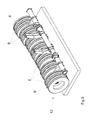
- the roller 1 according to the Fig. 1 to 7 is assigned to a harrow and / or distributor.
- the bottom roller is coupled to the frame of the harrow and / or the drill.
- the bottom roller 1 is used in addition to the condensing of loosened soil as a chassis for as Agricultural implement and / or distributor trained agricultural implement, as will be explained below.
- the roller 1 has a transversely to the direction of travel 4 extending support beam 5, on which are arranged on non-rotatably mounted on the support beam 5 wings 6 mounted on axles 7 wheels 8.
- the wheels 8 have tires that form a tire packer in the manner of a divided roller.
- the tires 8 are arranged side by side in series.
- the tires 8 of the roller 1 in the direction of travel 4 are offset from one another.
- the tires 8 are seen by means of the wings 6 seen in plan view with respect to the direction of travel 4, arranged so that a trailed by the foremost region 9 of the tire 8 curve creates a back pressed through envelope 10.
- the curve applied to the foremost circumferential surface 9 of the tires 8 of the roller 1 in working position runs curved in the view from above in such a way that with respect to the direction of travel 4, the envelope 10 is concave.
- the arrangement in an even number of tires 8 of a roll 1, the arrangement is chosen so that the two middle tires 8 'are at the same height and not offset from one another.
- this embodiment which is used for example in a 3 m chassis or 3 m wide machine application, so has a total of six tires 8.
- the roller 1 is so arranged on the frame of the harrow and / or the distributor that the roller 1 by rotating the support beam 5 to the transverse to the direction of travel 4
- the roller 1 forms the chassis for transport.
- the tires 8 serving as a suspension roller 1 are lowered into a transport position and raised in a working position.
- the tires 8 are arranged by means of the wings 6 in the transport position of the device on the support beam 5, that an applied to the footprint 9 of the tire 8 on the ground curve 10 has a rising to the center of the device course.
- the envelope 10 is slightly arched extending and has a concave shape.
- the respective laterally outermost tire 8 "of the roller 1 is associated with a braking device (not shown).
- the fact that the tires 8 are arranged in accordance with the invention causes the laterally outermost tires 8" of the roller 1 to be subjected to the highest vertical load in the transport position. This results in both a good driving and braking behavior for the chassis of the device.
- the roller 12 according to the 8 to 11 is intended for example for a 3.5 m wide device with a correspondingly wide chassis.
- the tires 8 are again arranged such that according to the transport position after Fig. 11 an applied to the footprint 9 of the tire 8 on the ground envelope 10 to one Center of the device has rising course.
- this envelope 10 is designed concave running.
- the roller 13 according to the Fig. 12 to 15 is intended for example for a 4 m wide device with a correspondingly wide chassis.
- the tires 8 are again arranged such that according to the transport position after Fig. 15 an applied to the footprint 9 of the tire 8 on the ground envelope 10 has a rising to the center of the device course.
- this envelope 10 is designed concave running.
- Fig. 16 to 19 is the middle part of the roller 14 of an example 6 m wide device with at the middle part of the roller 14 subsequent folding, but not shown side parts of roller elements shown.
- the middle part of the roller 14 has six tire elements 8 which are partially offset from one another.
- the two respective outer tires 8 ' are arranged at the same height by means of the wings 6 on the support beam 5 so that they can simultaneously accommodate a large vertical load of the heavy and wide machine.
- the tires 8 are partially arranged, in particular in the central region, so that an envelope 10 applied to the middle region of the contact surface 9 of the tires 8 on the ground has a course increasing towards the center of the device, so that the envelope 10 concave.
Landscapes
- Life Sciences & Earth Sciences (AREA)
- Engineering & Computer Science (AREA)
- Mechanical Engineering (AREA)
- Soil Sciences (AREA)
- Environmental Sciences (AREA)
- Soil Working Implements (AREA)
- Tires In General (AREA)
- Agricultural Machines (AREA)
Abstract
Description
- Die Erfindung betrifft ein Fahrwerk für ein landwirtschaftliches Gerät gemäß des Oberbegriffes des Patentanspruches 1.
- Ein derartiges Fahrwerk für ein landwirtschaftliches Gerät ist beispielsweise durch die
DE 197 46 927 C2 bekannt. Diese landwirtschaftliche Maschine ist als Sämaschine ausgebildet und weist im hinteren Bereich zueinander versetzte Stützräder auf, wobei die dem mittleren Bereich der Sämaschine zugeordneten Stützräder als Fahrwerk dienen können. Beim Befahren von Straßen und/oder Wegen mit einer zentralen Dammkrone ergibt sich ein instabiles Fahrverhalten. - Um diesem Problem entgegenzuwirken, ist es durch die
EP 1 510 119 B1 bekannt, die im Mittelbereich neben den äußeren der als Fahrwerk dienenden Räder für den Transportangeordneten Rädern vom Rahmen zu entkoppeln. Dann stützt sich die Maschine nur auf den äußeren Rädern ab, so dass sich ein stabiles Fahrverhalten beim Transport ergibt. Diese Ausgestaltung ist jedoch sehr aufwändig. Weiterhin sind sämtliche Räder der Walze in einer Linie angeordnet, dies hat Verstopfungsprobleme zur Folge. - Der Erfindung liegt die Aufgabe zu Grunde, auf einfache Weise ohne zusätzliche Umstellmaßnahmen ein stabiles Fahr- und Bremsverhalten des Gerätes auch auf Straßen und Wegen mit zentralen Dammkronen zu erreichen.
- Diese Aufgabe wird erfindungsgemäß dadurch gelöst, dass zumindest einige der Reifen mittels der Schwingen in Transportstellung des Gerätes derart an dem Tragbalken angeordnet sind, dass eine an die Aufstandsfläche der Reifen auf dem Boden angelegte Hüllkurve einen zur Mitte des Gerätes ansteigenden Verlauf aufweist.
- Infolge dieser Maßnahme wird bei Fahrwerken für landwirtschaftliche Geräte, bei denen in erfindungsgemäßer Weise die Reifen der Walze in Fahrtrichtung entsprechend zueinander versetzt sind, durch die Umstellung von der Arbeitsposition auf die Transportposition in überraschend einfacher Weise erreicht, dass im wesentlichen nur äußere Räder als Fahrwerk dienen, das heißt, dass diese Räder mit der größten Belastung von dem Gewicht des Gerätes beaufschlagt werden. Somit ergibt sich also auch gleichzeitig ein sehr gutes Bremsverhalten für das Gerät, wenn äußere Räder, die der größten Belastung unterliegen, für das Bremsen des Gerätes mit Bremseinrichtungen versehen sind.
- Eine vorteilhafte Anordnung der Räder in erfindungsgemäßer Weise lässt sich dadurch erreichen, dass die Hüllkurve torbogenförmig verläuft.
- Um das erfindungsgemäße stabile Fahr- und Bremsverhalten in einfacher Weise zu erreichen, ist vorgesehen, dass die Hüllkurve konkav verläuft.
- Um die erfindungsgemäße Anordnung und Wirkung in einfacher Weise zu erreichen, ist vorgesehen, dass einer an die vorderste und/oder hinterste Umfangsfläche der Reifen der sich in Arbeitsstellung befindlichen Walze angelegten Hüllkurve in der Ansicht von oben gekrümmt verläuft und zwar derart, dass bezogen auf die Fahrtrichtung die Hüllkurve konkav ausgestaltet ist.
- Um ein stabiles und gutes Bremsverhalten des Gerätes zu erreichen, ist vorgesehen, dass zumindest den jeweils seitlich äußersten Reifen der Walze eine Bremseinrichtung zugeordnet ist.
- Zusammenfassend sei noch auf folgendes hingewiesen:
- Die die als Reifen ausgebildeten Räder der Walzen haben einen gewissen Achsversatz zueinander. Hierdurch gibt es immer eine Relativbewegung der Reifen unter einander und die Verstopfungsempfindlichkeit nimmt ab. Bei der Transportfahrt lastet das Gewicht der Maschine auf den äußeren Reifen, so dass auf mittig überhöhten Straßen und/oder Wegen die Kippgefahr abnimmt und die das Gewicht tragenden äußeren Räder mit einer Bremse ausgestattet werden können, um die Maschine bremsen zu können.
- Weitere Einzelheiten der Erfindung sind der Beispielsbeschreibung und den Zeichnungen zu entnehmen. Hierbei zeigen
- Fig. 1
- die als Fahrwerk ausgebildete Walze des landwirtschaftlichen Gerätes in Arbeitsstellung und perspektivischer Darstellung,
- Fig. 2
- die als Fahrwerk ausgebildete Walze des landwirtschaftlichen Gerätes in Arbeitsstellung und Seitenansicht,
- Fig. 3
- die als Fahrwerk ausgebildete Walze des landwirtschaftlichen Gerätes in Arbeitsstellung und in der Ansicht von vorne,
- Fig. 4
- die als Fahrwerk ausgebildete Walze des landwirtschaftlichen Gerätes in Arbeitsstellung und in der Draufsicht,
- Fig. 5
- die als Fahrwerk ausgebildete Walze des landwirtschaftlichen Gerätes in Transportstellung und perspektivischer Darstellung,
- Fig. 6
- die als Fahrwerk ausgebildete Walze des landwirtschaftlichen Gerätes in Transportstellung und Seitenansicht,
- Fig. 7
- die als Fahrwerk ausgebildete Walze des landwirtschaftlichen Gerätes in Transportstellung und in der Ansicht von vorne,
- Fig. 8
- eine weitere als Fahrwerk ausgebildete Walze des landwirtschaftlichen Gerätes in Arbeitsstellung und perspektivischer Darstellung,
- Fig. 9
- die als Fahrwerk ausgebildete Walze des landwirtschaftlichen Gerätes gemäß
Fig. 8 in Arbeitsstellung und in der Ansicht von vorne, - Fig. 10
- die als Fahrwerk ausgebildete Walze des landwirtschaftlichen Gerätes gemäß
Fig. 8 in Arbeitsstellung und in der Draufsicht, - Fig. 11
- die als Fahrwerk ausgebildete Walze des landwirtschaftlichen Gerätes gemäß
Fig. 8 in Transportstellung und in der Ansicht von vorne, - Fig. 12
- eine weitere als Fahrwerk ausgebildete Walze des landwirtschaftlichen Gerätes in Arbeitsstellung und perspektivischer Darstellung,
- Fig. 13
- die als Fahrwerk ausgebildete Walze des landwirtschaftlichen Gerätes gemäß
Fig. 12 in Arbeitsstellung und in der Ansicht von vorne, - Fig. 14
- die als Fahrwerk ausgebildete Walze des landwirtschaftlichen Gerätes gemäß
Fig. 12 in Arbeitsstellung und in der Draufsicht, - Fig. 15
- die als Fahrwerk ausgebildete Walze des landwirtschaftlichen Gerätes gemäß
Fig. 12 in Transportstellung und in der Ansicht von vorne, - Fig. 16
- eine weitere als Fahrwerk ausgebildete Walze des landwirtschaftlichen Gerätes in Arbeitsstellung und perspektivischer Darstellung,
- Fig. 17
- die als Fahrwerk ausgebildete Walze des landwirtschaftlichen Gerätes gemäß
Fig. 16 in Arbeitsstellung und in der Ansicht von vorne, - Fig. 18
- die als Fahrwerk ausgebildete Walze des landwirtschaftlichen Gerätes gemäß
Fig. 16 in Arbeitsstellung und in der Draufsicht und - Fig. 19
- die als Fahrwerk ausgebildete Walze des landwirtschaftlichen Gerätes gemäß
Fig. 16 in Transportstellung und in der Ansicht von vorne. - Die Walze 1 gemäß den
Fig. 1 bis 7 ist einem Bodenbearbeitungsgerät und/oder Verteilmaschine zugeordnet. Über die Kupplungselemente 2 ist die Bodenwalze mit dem Rahmen des Bodenbearbeitungsgerätes und/oder der Sämaschine gekoppelt. Die Bodenwalze 1 dient neben dem verdichten von gelockertem Boden auch als Fahrwerk für das als Bodenbearbeitungsgerät und/oder Verteilmaschine ausgebildete landwirtschaftliche Gerät, wie weiter unten noch erläutert wird. - Die Walze 1 weist einen sich quer zur Fahrtrichtung 4 erstreckenden Tragbalken 5 auf, an dem über drehfest an dem Tragbalken 5 angeordnete Schwingen 6 die auf Achsen 7 gelagerten Räder 8 befestigt sind. Die Räder 8 weisen Reifen auf, die einen Reifenpacker nach Art einer unterteilten Walze bilden. Die Reifen 8 sind nebeneinander in Reihe angeordnet. In Arbeitsstellung, wie in den
Fig. 1 bis 4 gezeigt, sind die Reifen 8 der Walze 1 in Fahrtrichtung 4 versetzt zueinander angeordnet. Hierbei sind die Reifen 8 mittels der Schwingen 6 in der Draufsicht gesehen bezogen auf die Fahrtrichtung 4, so angeordnet, dass eine durch den vordersten Bereich 9 der Reifen 8 gezogene Kurve eine nach hinten durchgedrückte Hüllkurve 10 entsteht. Somit verläuft die an die vorderste Umfangsfläche 9 der Reifen 8 der sich in Arbeitsstellung befindlichen Walze 1 angelegten Kurve in der Ansicht von oben gekrümmt und zwar derart, dass bezogen auf die Fahrtrichtung 4 die Hüllkurve 10 konkav ausgestaltet ist. - Hierbei ist bei diesem Ausführungsbeispiel bei einer geraden Anzahl von Reifen 8 einer Walze 1 die Anordnung so gewählt, dass die beiden mittleren Reifen 8' auf gleicher Höhe und nicht zueinander versetzt sind. Bei diesem Ausführungsbeispiel, die beispielsweise bei einem 3 m Fahrwerk oder 3 m breiten Maschine Anwendung findet, weist also insgesamt sechs Reifen 8 auf.
- Über die Kupplungselemente 2 und 3 ist die Walze 1 derart am Rahmen des Bodenbearbeitungsgerätes und/oder der Verteilmaschine angeordnet, dass die Walze 1 durch verdrehen des Tragbalkens 5 um die quer zur Fahrtrichtung 4 verlaufende Drehachse 11 aus der in den
Fig. 1 bis 4 dargestellten Arbeitsstellung in die in denFig. 5 bis 7 dargestellten Transportstellung mittels der als Hydraulikzylinder 3 ausgebildeten oberen Kupplungselemente zu verschwenken ist. In der Transportstellung bildet die Walze 1 für den Transport das Fahrwerk. Durch das Verschwenken der Walze 1 sind die Reifen 8 der als Fahrwerk dienenden Walze 1 in eine Transportstellung absenkbar und in einer Arbeitsstellung anhebbar. - Bezogen auf die Transportstellung gemäß den
Fig. 5 - 7 sind die Reifen 8 mittels der Schwingen 6 in Transportstellung des Gerätes derart an dem Tragbalken 5 angeordnet, dass eine an die Aufstandsfläche 9 der Reifen 8 auf dem Boden angelegte Kurve 10 einen zu Mitte des Gerätes ansteigenden Verlauf aufweist. Somit ist die Hüllkurve 10 leicht torbogenförmig verlaufend ausgestaltet und weist einen konkaven Verlauf auf. - Die jeweils seitlich äußersten Reifen 8" der Walze 1 ist eine nicht dargestellte Bremseinrichtung zugeordnet. Dadurch, dass die Reifen 8 in erfindungsgemäßer Weise angeordnet sind, werden die seitlich äußersten Reifen 8" der Walze 1 mit der höchsten Stützlast in Transportstellung beaufschlagt. Hierdurch ergibt sich sowohl ein gutes Fahr- wie auch Bremsverhalten für das Fahrwerk des Gerätes.
- Die Walze 12 gemäß den
Fig. 8 bis 11 ist beispielsweise für ein 3,5 m breites Gerät mit einem entsprechend breiten Fahrwerk vorgesehen. Hierbei sind die drei mittleren Reifen 8' nicht versetzt zueinander angeordnet. Die Reifen 8 sind jedoch wiederum derart angeordnet, dass gemäß der Transportstellung nachFig. 11 einer an die Aufstandsfläche 9 der Reifen 8 auf dem Boden angelegte Hüllkurve 10 einen zu Mitte des Gerätes ansteigenden Verlauf aufweist. Auch diese Hüllkurve 10 ist konkav verlaufend ausgestaltet. - Die Walze 13 gemäß den
Fig. 12 bis 15 ist beispielsweise für eine 4 m breites Gerät mit einem entsprechend breiten Fahrwerk vorgesehen. Hierbei sind die vier mittleren Reifen 8' nicht versetzt zueinander angeordnet. Die Reifen 8 sind jedoch wiederum derart angeordnet, dass gemäß der Transportstellung nachFig. 15 einer an die Aufstandsfläche 9 der Reifen 8 auf dem Boden angelegte Hüllkurve 10 einen zu Mitte des Gerätes ansteigenden Verlauf aufweist. Auch diese Hüllkurve 10 ist konkav verlaufend ausgestaltet. - Gemäß den
Fig. 16 bis 19 ist der mittlere Teil der Walze 14 eines beispielsweise 6 m breiten Gerätes mit sich an dem mittleren Teil der Walze 14 anschließenden einklappbaren, jedoch nicht dargestellten Seitenteilen von Walzenelementen dargestellt. Der mittlere Teil der Walze 14 weist sechs Reifenelemente 8 auf die teilweise versetzt zueinander angeordnet sind. Die beiden jeweils äußeren Reifen 8' sind auf gleicher Höhe mittels der Schwingen 6 am Tragbalken 5 angeordnet, damit sie gleichzeitig eine große Stützlast der schweren und breiten Maschine aufnehmen können. Auch hier sind die Reifen 8 teilweise, insbesondere auf den mittleren Bereich bezogen, so angeordnet, dass eine an dem mittleren Bereich der Aufstandsfläche 9 der Reifen 8 auf dem Boden angelegte Hüllkurve 10 einen zu Mitte des Gerätes ansteigenden Verlauf aufweist, so dass die Hüllkurve 10 konkav verläuft.
Claims (5)
- Fahrwerk für ein landwirtschaftliches Gerät, insbesondere Bodenbearbeitungs- und/oder Verteilmaschine, mit mehreren nebeneinander in Reihe angeordneten Reifen, die einen Reifenpacker nach Art einer unterteilten Walze bilden, wobei die Reifen mittels drehfest an einem sich quer zur Fahrtrichtung des Gerätes erstreckenden Tragbalken angeordneten Schwingen angeordnet sind, wobei in Arbeitsstellung der Walze zumindest einige der Reifen, die einander benachbart sind, in Fahrtrichtung versetzt zueinander angeordnet sind, wobei die Reifen der Walze durch Verdrehen des Tragbalkens um eine quer zur Fahrtrichtung verlaufende Drehachse aus der Arbeitsstellung in eine Transportstellung, in welcher zumindest einige der Reifen das Fahrwerk des Gerätes bilden, absenkbar und aus einer Transportstellung in eine Arbeitsstellung anhebbar sind, dadurch gekennzeichnet, dass zumindest einige der Reifen mittels der Schwingen in Transportstellung des Gerätes derart an dem Tragbalken (5) angeordnet sind, dass eine an die Aufstandsfläche (9) der Reifen (8)auf dem Boden angelegte Hüllkurve (10) einen zur Mitte des Gerätes ansteigenden Verlauf aufweist.
- Fahrwerk nach Anspruch 1, dadurch gekennzeichnet, dass die Hüllkurve (10) torbogenförmig verläuft.
- Fahrwerk nach Anspruch 1, dadurch gekennzeichnet, dass die Hüllkurve (10) konkav verläuft.
- Fahrwerk nach zumindest einem der vorstehenden Ansprüche, dadurch gekennzeichnet, dass einer an die vorderste vorderste und/oder hinterste Umfangsfläche (9) der Reifen (8) der sich in Arbeitsstellung befindlichen Walze (1, 12, 13, 14) angelegten Hüllkurve (10) in der Ansicht von oben gekrümmt verläuft und zwar derart, dass bezogen auf die Fahrtrichtung (4) die Hüllkurve (10) konkav ausgestaltet ist.
- Fahrwerk nach zumindest einem der vorstehenden Ansprüche, dadurch gekennzeichnet, dass zumindest den jeweils seitlich äußersten Reifen (8') der Walze (1, 12, 13, 14) eine Bremseinrichtung zugeordnet ist.
Applications Claiming Priority (1)
| Application Number | Priority Date | Filing Date | Title |
|---|---|---|---|
| DE201010037108 DE102010037108A1 (de) | 2010-08-23 | 2010-08-23 | Fahrwerk für ein landwirtschaftliches Gerät |
Publications (2)
| Publication Number | Publication Date |
|---|---|
| EP2422597A1 true EP2422597A1 (de) | 2012-02-29 |
| EP2422597B1 EP2422597B1 (de) | 2017-01-18 |
Family
ID=44903134
Family Applications (1)
| Application Number | Title | Priority Date | Filing Date |
|---|---|---|---|
| EP11401571.2A Active EP2422597B1 (de) | 2010-08-23 | 2011-08-15 | Fahrwerk für ein landwirtschaftliches Gerät |
Country Status (2)
| Country | Link |
|---|---|
| EP (1) | EP2422597B1 (de) |
| DE (1) | DE102010037108A1 (de) |
Cited By (1)
| Publication number | Priority date | Publication date | Assignee | Title |
|---|---|---|---|---|
| EP4616690A1 (de) * | 2024-03-13 | 2025-09-17 | Amazonen-Werke H. Dreyer SE & Co. KG | Landwirtschaftliches arbeitsgerät |
Families Citing this family (1)
| Publication number | Priority date | Publication date | Assignee | Title |
|---|---|---|---|---|
| EP4465806A1 (de) * | 2022-01-20 | 2024-11-27 | Lemken GmbH & Co KG | Landwirtschaftliches arbeitsgerät |
Citations (6)
| Publication number | Priority date | Publication date | Assignee | Title |
|---|---|---|---|---|
| DE19746927C2 (de) | 1997-10-23 | 1999-09-30 | Horsch Maschinen Gmbh | Landwirtschaftliche Maschine |
| WO2003037063A1 (en) * | 2001-10-31 | 2003-05-08 | Kaastrup Soeren | Soil compacter for connection of a tool |
| WO2005115124A1 (de) * | 2004-05-29 | 2005-12-08 | Amazonen-Werke H. Dreyer Gnbh & Co. Kg | Fahrwerk für landwirtschaftliche bodenbearbeitungsmaschine |
| EP1614335A2 (de) * | 2004-06-25 | 2006-01-11 | Amazonen-Werke H. Dreyer GmbH & Co. KG | Fahrwerk |
| FR2886511A1 (fr) * | 2005-06-07 | 2006-12-08 | Michel Evin | Machine de travail du sol a chassis tracte relevable comportant des roues formant indifferemment roues de jauge et de transport |
| EP1510119B1 (de) | 2003-08-25 | 2009-03-18 | Alois Pöttinger Maschinenfabrik Ges. m.b.H. | Fahrwerk für eine landwirtschaftliche Bodenbearbeitungsmaschine |
-
2010
- 2010-08-23 DE DE201010037108 patent/DE102010037108A1/de not_active Withdrawn
-
2011
- 2011-08-15 EP EP11401571.2A patent/EP2422597B1/de active Active
Patent Citations (6)
| Publication number | Priority date | Publication date | Assignee | Title |
|---|---|---|---|---|
| DE19746927C2 (de) | 1997-10-23 | 1999-09-30 | Horsch Maschinen Gmbh | Landwirtschaftliche Maschine |
| WO2003037063A1 (en) * | 2001-10-31 | 2003-05-08 | Kaastrup Soeren | Soil compacter for connection of a tool |
| EP1510119B1 (de) | 2003-08-25 | 2009-03-18 | Alois Pöttinger Maschinenfabrik Ges. m.b.H. | Fahrwerk für eine landwirtschaftliche Bodenbearbeitungsmaschine |
| WO2005115124A1 (de) * | 2004-05-29 | 2005-12-08 | Amazonen-Werke H. Dreyer Gnbh & Co. Kg | Fahrwerk für landwirtschaftliche bodenbearbeitungsmaschine |
| EP1614335A2 (de) * | 2004-06-25 | 2006-01-11 | Amazonen-Werke H. Dreyer GmbH & Co. KG | Fahrwerk |
| FR2886511A1 (fr) * | 2005-06-07 | 2006-12-08 | Michel Evin | Machine de travail du sol a chassis tracte relevable comportant des roues formant indifferemment roues de jauge et de transport |
Cited By (1)
| Publication number | Priority date | Publication date | Assignee | Title |
|---|---|---|---|---|
| EP4616690A1 (de) * | 2024-03-13 | 2025-09-17 | Amazonen-Werke H. Dreyer SE & Co. KG | Landwirtschaftliches arbeitsgerät |
Also Published As
| Publication number | Publication date |
|---|---|
| EP2422597B1 (de) | 2017-01-18 |
| DE102010037108A1 (de) | 2012-02-23 |
Similar Documents
| Publication | Publication Date | Title |
|---|---|---|
| EP2605632B1 (de) | Gezogene landwirtschaftliche maschine mit packereinheit und verfahren zur handhabung einer solchen maschine | |
| EP2443915A1 (de) | Fahrwerk für ein landwirtschaftliches Gerät | |
| EP2988584B1 (de) | Bodenbearbeitungsgerät zum anbau an ein zugfahrzeug | |
| EP1594355B1 (de) | Landwirtschaftliches arbeitsgerät | |
| EP0427154B1 (de) | Bodenbearbeitungsgerät | |
| DE3011212A1 (de) | Heuwerbungsmaschine | |
| EP4492954A1 (de) | LANDWIRTSCHAFTLICHES ARBEITSGERÄT MIT GROßER ARBEITSBREITE | |
| EP2281424B1 (de) | Bodenbearbeitungsvorrichtung | |
| DE1296861B (de) | Bodenbearbeitungsmaschine | |
| DE1482828C3 (de) | Radrechwender | |
| EP2422597B1 (de) | Fahrwerk für ein landwirtschaftliches Gerät | |
| EP0891691A1 (de) | Sägerät mit einem Scheibensäschar | |
| DE19630079A1 (de) | Bodenbearbeitungsgerät mit Hohlscheiben | |
| DE2622444C3 (de) | Anbauvorrichtung für landwirtschaftliche Verteilmaschinen | |
| WO2016110290A1 (de) | Landwirtschaftliches arbeitsgerät mit zusatzfahrwerk | |
| DE102014106953A1 (de) | Fahrwerk einer landwirtschaftlichen Maschine | |
| EP3620037B1 (de) | Bodenbearbeitungsgerät | |
| EP1911339B1 (de) | Doppelscheibenschar mit Tiefenführungsrolle und Energiespeicher | |
| DE3336313C2 (de) | Bodenstützgerät für eine Landmaschine | |
| DE3308942C2 (de) | ||
| DE102018004261A1 (de) | Parallelogrammgeführte Säscharaufhängung mit integrierter vertikaler Drehachse zwischen Parallelogramm und Säscharhalterung mit mechanischer Überlastsicherung und mit mindestens einer progressiven, einer festen und mindestens einer degressiven mechanischen Schardruckeinstellung mit Andruckrollentiefenführung an der Säscharhalterung | |
| EP0359896A2 (de) | Kombinationsgerät | |
| DE102005030923A1 (de) | Landwirtschaftsmaschine in Form einer Scheibenegge | |
| EP0222930A1 (de) | Tiefenlockerer | |
| DE102004002514B3 (de) | Selbstreinigende Ackerwalze |
Legal Events
| Date | Code | Title | Description |
|---|---|---|---|
| AK | Designated contracting states |
Kind code of ref document: A1 Designated state(s): AL AT BE BG CH CY CZ DE DK EE ES FI FR GB GR HR HU IE IS IT LI LT LU LV MC MK MT NL NO PL PT RO RS SE SI SK SM TR |
|
| AX | Request for extension of the european patent |
Extension state: BA ME |
|
| PUAI | Public reference made under article 153(3) epc to a published international application that has entered the european phase |
Free format text: ORIGINAL CODE: 0009012 |
|
| 17P | Request for examination filed |
Effective date: 20120810 |
|
| GRAP | Despatch of communication of intention to grant a patent |
Free format text: ORIGINAL CODE: EPIDOSNIGR1 |
|
| RIC1 | Information provided on ipc code assigned before grant |
Ipc: A01B 29/06 20060101ALI20160825BHEP Ipc: A01B 73/00 20060101ALI20160825BHEP Ipc: A01B 29/04 20060101AFI20160825BHEP |
|
| INTG | Intention to grant announced |
Effective date: 20160912 |
|
| GRAS | Grant fee paid |
Free format text: ORIGINAL CODE: EPIDOSNIGR3 |
|
| GRAA | (expected) grant |
Free format text: ORIGINAL CODE: 0009210 |
|
| AK | Designated contracting states |
Kind code of ref document: B1 Designated state(s): AL AT BE BG CH CY CZ DE DK EE ES FI FR GB GR HR HU IE IS IT LI LT LU LV MC MK MT NL NO PL PT RO RS SE SI SK SM TR |
|
| REG | Reference to a national code |
Ref country code: GB Ref legal event code: FG4D Free format text: NOT ENGLISH |
|
| REG | Reference to a national code |
Ref country code: CH Ref legal event code: EP |
|
| REG | Reference to a national code |
Ref country code: AT Ref legal event code: REF Ref document number: 862337 Country of ref document: AT Kind code of ref document: T Effective date: 20170215 |
|
| REG | Reference to a national code |
Ref country code: IE Ref legal event code: FG4D Free format text: LANGUAGE OF EP DOCUMENT: GERMAN |
|
| REG | Reference to a national code |
Ref country code: DE Ref legal event code: R096 Ref document number: 502011011545 Country of ref document: DE |
|
| REG | Reference to a national code |
Ref country code: SE Ref legal event code: TRGR |
|
| REG | Reference to a national code |
Ref country code: NL Ref legal event code: MP Effective date: 20170118 |
|
| REG | Reference to a national code |
Ref country code: LT Ref legal event code: MG4D |
|
| PG25 | Lapsed in a contracting state [announced via postgrant information from national office to epo] |
Ref country code: NL Free format text: LAPSE BECAUSE OF FAILURE TO SUBMIT A TRANSLATION OF THE DESCRIPTION OR TO PAY THE FEE WITHIN THE PRESCRIBED TIME-LIMIT Effective date: 20170118 |
|
| REG | Reference to a national code |
Ref country code: FR Ref legal event code: PLFP Year of fee payment: 7 |
|
| PG25 | Lapsed in a contracting state [announced via postgrant information from national office to epo] |
Ref country code: IS Free format text: LAPSE BECAUSE OF FAILURE TO SUBMIT A TRANSLATION OF THE DESCRIPTION OR TO PAY THE FEE WITHIN THE PRESCRIBED TIME-LIMIT Effective date: 20170518 Ref country code: GR Free format text: LAPSE BECAUSE OF FAILURE TO SUBMIT A TRANSLATION OF THE DESCRIPTION OR TO PAY THE FEE WITHIN THE PRESCRIBED TIME-LIMIT Effective date: 20170419 Ref country code: HR Free format text: LAPSE BECAUSE OF FAILURE TO SUBMIT A TRANSLATION OF THE DESCRIPTION OR TO PAY THE FEE WITHIN THE PRESCRIBED TIME-LIMIT Effective date: 20170118 Ref country code: NO Free format text: LAPSE BECAUSE OF FAILURE TO SUBMIT A TRANSLATION OF THE DESCRIPTION OR TO PAY THE FEE WITHIN THE PRESCRIBED TIME-LIMIT Effective date: 20170418 Ref country code: FI Free format text: LAPSE BECAUSE OF FAILURE TO SUBMIT A TRANSLATION OF THE DESCRIPTION OR TO PAY THE FEE WITHIN THE PRESCRIBED TIME-LIMIT Effective date: 20170118 Ref country code: LT Free format text: LAPSE BECAUSE OF FAILURE TO SUBMIT A TRANSLATION OF THE DESCRIPTION OR TO PAY THE FEE WITHIN THE PRESCRIBED TIME-LIMIT Effective date: 20170118 |
|
| PG25 | Lapsed in a contracting state [announced via postgrant information from national office to epo] |
Ref country code: LV Free format text: LAPSE BECAUSE OF FAILURE TO SUBMIT A TRANSLATION OF THE DESCRIPTION OR TO PAY THE FEE WITHIN THE PRESCRIBED TIME-LIMIT Effective date: 20170118 Ref country code: PT Free format text: LAPSE BECAUSE OF FAILURE TO SUBMIT A TRANSLATION OF THE DESCRIPTION OR TO PAY THE FEE WITHIN THE PRESCRIBED TIME-LIMIT Effective date: 20170518 Ref country code: ES Free format text: LAPSE BECAUSE OF FAILURE TO SUBMIT A TRANSLATION OF THE DESCRIPTION OR TO PAY THE FEE WITHIN THE PRESCRIBED TIME-LIMIT Effective date: 20170118 Ref country code: BG Free format text: LAPSE BECAUSE OF FAILURE TO SUBMIT A TRANSLATION OF THE DESCRIPTION OR TO PAY THE FEE WITHIN THE PRESCRIBED TIME-LIMIT Effective date: 20170418 Ref country code: RS Free format text: LAPSE BECAUSE OF FAILURE TO SUBMIT A TRANSLATION OF THE DESCRIPTION OR TO PAY THE FEE WITHIN THE PRESCRIBED TIME-LIMIT Effective date: 20170118 Ref country code: PL Free format text: LAPSE BECAUSE OF FAILURE TO SUBMIT A TRANSLATION OF THE DESCRIPTION OR TO PAY THE FEE WITHIN THE PRESCRIBED TIME-LIMIT Effective date: 20170118 |
|
| REG | Reference to a national code |
Ref country code: DE Ref legal event code: R097 Ref document number: 502011011545 Country of ref document: DE |
|
| PG25 | Lapsed in a contracting state [announced via postgrant information from national office to epo] |
Ref country code: EE Free format text: LAPSE BECAUSE OF FAILURE TO SUBMIT A TRANSLATION OF THE DESCRIPTION OR TO PAY THE FEE WITHIN THE PRESCRIBED TIME-LIMIT Effective date: 20170118 Ref country code: RO Free format text: LAPSE BECAUSE OF FAILURE TO SUBMIT A TRANSLATION OF THE DESCRIPTION OR TO PAY THE FEE WITHIN THE PRESCRIBED TIME-LIMIT Effective date: 20170118 Ref country code: CZ Free format text: LAPSE BECAUSE OF FAILURE TO SUBMIT A TRANSLATION OF THE DESCRIPTION OR TO PAY THE FEE WITHIN THE PRESCRIBED TIME-LIMIT Effective date: 20170118 Ref country code: SK Free format text: LAPSE BECAUSE OF FAILURE TO SUBMIT A TRANSLATION OF THE DESCRIPTION OR TO PAY THE FEE WITHIN THE PRESCRIBED TIME-LIMIT Effective date: 20170118 Ref country code: IT Free format text: LAPSE BECAUSE OF FAILURE TO SUBMIT A TRANSLATION OF THE DESCRIPTION OR TO PAY THE FEE WITHIN THE PRESCRIBED TIME-LIMIT Effective date: 20170118 |
|
| PLBE | No opposition filed within time limit |
Free format text: ORIGINAL CODE: 0009261 |
|
| STAA | Information on the status of an ep patent application or granted ep patent |
Free format text: STATUS: NO OPPOSITION FILED WITHIN TIME LIMIT |
|
| PG25 | Lapsed in a contracting state [announced via postgrant information from national office to epo] |
Ref country code: DK Free format text: LAPSE BECAUSE OF FAILURE TO SUBMIT A TRANSLATION OF THE DESCRIPTION OR TO PAY THE FEE WITHIN THE PRESCRIBED TIME-LIMIT Effective date: 20170118 Ref country code: SM Free format text: LAPSE BECAUSE OF FAILURE TO SUBMIT A TRANSLATION OF THE DESCRIPTION OR TO PAY THE FEE WITHIN THE PRESCRIBED TIME-LIMIT Effective date: 20170118 |
|
| 26N | No opposition filed |
Effective date: 20171019 |
|
| PG25 | Lapsed in a contracting state [announced via postgrant information from national office to epo] |
Ref country code: SI Free format text: LAPSE BECAUSE OF FAILURE TO SUBMIT A TRANSLATION OF THE DESCRIPTION OR TO PAY THE FEE WITHIN THE PRESCRIBED TIME-LIMIT Effective date: 20170118 |
|
| REG | Reference to a national code |
Ref country code: CH Ref legal event code: PL |
|
| PG25 | Lapsed in a contracting state [announced via postgrant information from national office to epo] |
Ref country code: MC Free format text: LAPSE BECAUSE OF FAILURE TO SUBMIT A TRANSLATION OF THE DESCRIPTION OR TO PAY THE FEE WITHIN THE PRESCRIBED TIME-LIMIT Effective date: 20170118 |
|
| GBPC | Gb: european patent ceased through non-payment of renewal fee |
Effective date: 20170815 |
|
| PG25 | Lapsed in a contracting state [announced via postgrant information from national office to epo] |
Ref country code: CH Free format text: LAPSE BECAUSE OF NON-PAYMENT OF DUE FEES Effective date: 20170831 Ref country code: LI Free format text: LAPSE BECAUSE OF NON-PAYMENT OF DUE FEES Effective date: 20170831 |
|
| REG | Reference to a national code |
Ref country code: IE Ref legal event code: MM4A |
|
| REG | Reference to a national code |
Ref country code: BE Ref legal event code: MM Effective date: 20170831 |
|
| PG25 | Lapsed in a contracting state [announced via postgrant information from national office to epo] |
Ref country code: LU Free format text: LAPSE BECAUSE OF NON-PAYMENT OF DUE FEES Effective date: 20170815 |
|
| REG | Reference to a national code |
Ref country code: FR Ref legal event code: PLFP Year of fee payment: 8 |
|
| PG25 | Lapsed in a contracting state [announced via postgrant information from national office to epo] |
Ref country code: IE Free format text: LAPSE BECAUSE OF NON-PAYMENT OF DUE FEES Effective date: 20170815 Ref country code: GB Free format text: LAPSE BECAUSE OF NON-PAYMENT OF DUE FEES Effective date: 20170815 |
|
| PG25 | Lapsed in a contracting state [announced via postgrant information from national office to epo] |
Ref country code: BE Free format text: LAPSE BECAUSE OF NON-PAYMENT OF DUE FEES Effective date: 20170831 |
|
| PG25 | Lapsed in a contracting state [announced via postgrant information from national office to epo] |
Ref country code: MT Free format text: LAPSE BECAUSE OF FAILURE TO SUBMIT A TRANSLATION OF THE DESCRIPTION OR TO PAY THE FEE WITHIN THE PRESCRIBED TIME-LIMIT Effective date: 20170118 |
|
| PG25 | Lapsed in a contracting state [announced via postgrant information from national office to epo] |
Ref country code: HU Free format text: LAPSE BECAUSE OF FAILURE TO SUBMIT A TRANSLATION OF THE DESCRIPTION OR TO PAY THE FEE WITHIN THE PRESCRIBED TIME-LIMIT; INVALID AB INITIO Effective date: 20110815 |
|
| PG25 | Lapsed in a contracting state [announced via postgrant information from national office to epo] |
Ref country code: CY Free format text: LAPSE BECAUSE OF NON-PAYMENT OF DUE FEES Effective date: 20170118 |
|
| PG25 | Lapsed in a contracting state [announced via postgrant information from national office to epo] |
Ref country code: MK Free format text: LAPSE BECAUSE OF FAILURE TO SUBMIT A TRANSLATION OF THE DESCRIPTION OR TO PAY THE FEE WITHIN THE PRESCRIBED TIME-LIMIT Effective date: 20170118 |
|
| PG25 | Lapsed in a contracting state [announced via postgrant information from national office to epo] |
Ref country code: TR Free format text: LAPSE BECAUSE OF FAILURE TO SUBMIT A TRANSLATION OF THE DESCRIPTION OR TO PAY THE FEE WITHIN THE PRESCRIBED TIME-LIMIT Effective date: 20170118 |
|
| PG25 | Lapsed in a contracting state [announced via postgrant information from national office to epo] |
Ref country code: AL Free format text: LAPSE BECAUSE OF FAILURE TO SUBMIT A TRANSLATION OF THE DESCRIPTION OR TO PAY THE FEE WITHIN THE PRESCRIBED TIME-LIMIT Effective date: 20170118 |
|
| REG | Reference to a national code |
Ref country code: DE Ref legal event code: R082 Ref document number: 502011011545 Country of ref document: DE Representative=s name: KILBURN & STRODE LLP, GB Ref country code: DE Ref legal event code: R082 Ref document number: 502011011545 Country of ref document: DE Representative=s name: KILBURN & STRODE LLP, NL Ref country code: DE Ref legal event code: R081 Ref document number: 502011011545 Country of ref document: DE Owner name: AMAZONEN-WERKE H. DREYER SE & CO. KG, DE Free format text: FORMER OWNER: AMAZONEN-WERKE H. DREYER GMBH & CO. KG, 49205 HASBERGEN, DE |
|
| REG | Reference to a national code |
Ref country code: DE Ref legal event code: R082 Ref document number: 502011011545 Country of ref document: DE Representative=s name: KILBURN & STRODE LLP, NL |
|
| P01 | Opt-out of the competence of the unified patent court (upc) registered |
Effective date: 20230524 |
|
| PGFP | Annual fee paid to national office [announced via postgrant information from national office to epo] |
Ref country code: FR Payment date: 20250610 Year of fee payment: 15 |
|
| PGFP | Annual fee paid to national office [announced via postgrant information from national office to epo] |
Ref country code: SE Payment date: 20250610 Year of fee payment: 15 |
|
| PGFP | Annual fee paid to national office [announced via postgrant information from national office to epo] |
Ref country code: DE Payment date: 20250618 Year of fee payment: 15 |
|
| PGFP | Annual fee paid to national office [announced via postgrant information from national office to epo] |
Ref country code: AT Payment date: 20250725 Year of fee payment: 15 |